EP3092064B1 - Mélangeur statique pour homogéneiser un mélange d'au moins deux liquides et dispositif de dosage équipé d'un tel mélangeur - Google Patents
Mélangeur statique pour homogéneiser un mélange d'au moins deux liquides et dispositif de dosage équipé d'un tel mélangeur Download PDFInfo
- Publication number
- EP3092064B1 EP3092064B1 EP15701249.3A EP15701249A EP3092064B1 EP 3092064 B1 EP3092064 B1 EP 3092064B1 EP 15701249 A EP15701249 A EP 15701249A EP 3092064 B1 EP3092064 B1 EP 3092064B1
- Authority
- EP
- European Patent Office
- Prior art keywords
- duct
- mixer
- container
- wall
- input
- Prior art date
- Legal status (The legal status is an assumption and is not a legal conclusion. Google has not performed a legal analysis and makes no representation as to the accuracy of the status listed.)
- Active
Links
Images



Classifications
-
- B—PERFORMING OPERATIONS; TRANSPORTING
- B01—PHYSICAL OR CHEMICAL PROCESSES OR APPARATUS IN GENERAL
- B01F—MIXING, e.g. DISSOLVING, EMULSIFYING OR DISPERSING
- B01F25/00—Flow mixers; Mixers for falling materials, e.g. solid particles
- B01F25/40—Static mixers
- B01F25/42—Static mixers in which the mixing is affected by moving the components jointly in changing directions, e.g. in tubes provided with baffles or obstructions
- B01F25/421—Static mixers in which the mixing is affected by moving the components jointly in changing directions, e.g. in tubes provided with baffles or obstructions by moving the components in a convoluted or labyrinthine path
-
- B—PERFORMING OPERATIONS; TRANSPORTING
- B01—PHYSICAL OR CHEMICAL PROCESSES OR APPARATUS IN GENERAL
- B01F—MIXING, e.g. DISSOLVING, EMULSIFYING OR DISPERSING
- B01F23/00—Mixing according to the phases to be mixed, e.g. dispersing or emulsifying
- B01F23/40—Mixing liquids with liquids; Emulsifying
- B01F23/45—Mixing liquids with liquids; Emulsifying using flow mixing
- B01F23/451—Mixing liquids with liquids; Emulsifying using flow mixing by injecting one liquid into another
-
- B—PERFORMING OPERATIONS; TRANSPORTING
- B01—PHYSICAL OR CHEMICAL PROCESSES OR APPARATUS IN GENERAL
- B01F—MIXING, e.g. DISSOLVING, EMULSIFYING OR DISPERSING
- B01F23/00—Mixing according to the phases to be mixed, e.g. dispersing or emulsifying
- B01F23/40—Mixing liquids with liquids; Emulsifying
-
- B—PERFORMING OPERATIONS; TRANSPORTING
- B01—PHYSICAL OR CHEMICAL PROCESSES OR APPARATUS IN GENERAL
- B01F—MIXING, e.g. DISSOLVING, EMULSIFYING OR DISPERSING
- B01F23/00—Mixing according to the phases to be mixed, e.g. dispersing or emulsifying
- B01F23/40—Mixing liquids with liquids; Emulsifying
- B01F23/45—Mixing liquids with liquids; Emulsifying using flow mixing
-
- B—PERFORMING OPERATIONS; TRANSPORTING
- B01—PHYSICAL OR CHEMICAL PROCESSES OR APPARATUS IN GENERAL
- B01F—MIXING, e.g. DISSOLVING, EMULSIFYING OR DISPERSING
- B01F25/00—Flow mixers; Mixers for falling materials, e.g. solid particles
- B01F25/30—Injector mixers
-
- B—PERFORMING OPERATIONS; TRANSPORTING
- B01—PHYSICAL OR CHEMICAL PROCESSES OR APPARATUS IN GENERAL
- B01F—MIXING, e.g. DISSOLVING, EMULSIFYING OR DISPERSING
- B01F25/00—Flow mixers; Mixers for falling materials, e.g. solid particles
- B01F25/30—Injector mixers
- B01F25/31—Injector mixers in conduits or tubes through which the main component flows
- B01F25/315—Injector mixers in conduits or tubes through which the main component flows wherein a difference of pressure at different points of the conduit causes introduction of the additional component into the main component
-
- B—PERFORMING OPERATIONS; TRANSPORTING
- B01—PHYSICAL OR CHEMICAL PROCESSES OR APPARATUS IN GENERAL
- B01F—MIXING, e.g. DISSOLVING, EMULSIFYING OR DISPERSING
- B01F25/00—Flow mixers; Mixers for falling materials, e.g. solid particles
- B01F25/30—Injector mixers
- B01F25/32—Injector mixers wherein the additional components are added in a by-pass of the main flow
-
- B—PERFORMING OPERATIONS; TRANSPORTING
- B01—PHYSICAL OR CHEMICAL PROCESSES OR APPARATUS IN GENERAL
- B01F—MIXING, e.g. DISSOLVING, EMULSIFYING OR DISPERSING
- B01F25/00—Flow mixers; Mixers for falling materials, e.g. solid particles
- B01F25/40—Static mixers
-
- B—PERFORMING OPERATIONS; TRANSPORTING
- B01—PHYSICAL OR CHEMICAL PROCESSES OR APPARATUS IN GENERAL
- B01F—MIXING, e.g. DISSOLVING, EMULSIFYING OR DISPERSING
- B01F35/00—Accessories for mixers; Auxiliary operations or auxiliary devices; Parts or details of general application
- B01F35/80—Forming a predetermined ratio of the substances to be mixed
-
- B—PERFORMING OPERATIONS; TRANSPORTING
- B01—PHYSICAL OR CHEMICAL PROCESSES OR APPARATUS IN GENERAL
- B01F—MIXING, e.g. DISSOLVING, EMULSIFYING OR DISPERSING
- B01F35/00—Accessories for mixers; Auxiliary operations or auxiliary devices; Parts or details of general application
- B01F35/80—Forming a predetermined ratio of the substances to be mixed
- B01F35/83—Forming a predetermined ratio of the substances to be mixed by controlling the ratio of two or more flows, e.g. using flow sensing or flow controlling devices
- B01F35/831—Forming a predetermined ratio of the substances to be mixed by controlling the ratio of two or more flows, e.g. using flow sensing or flow controlling devices using one or more pump or other dispensing mechanisms for feeding the flows in predetermined proportion, e.g. one of the pumps being driven by one of the flows
-
- F—MECHANICAL ENGINEERING; LIGHTING; HEATING; WEAPONS; BLASTING
- F04—POSITIVE - DISPLACEMENT MACHINES FOR LIQUIDS; PUMPS FOR LIQUIDS OR ELASTIC FLUIDS
- F04B—POSITIVE-DISPLACEMENT MACHINES FOR LIQUIDS; PUMPS
- F04B13/00—Pumps specially modified to deliver fixed or variable measured quantities
- F04B13/02—Pumps specially modified to deliver fixed or variable measured quantities of two or more fluids at the same time
-
- B—PERFORMING OPERATIONS; TRANSPORTING
- B01—PHYSICAL OR CHEMICAL PROCESSES OR APPARATUS IN GENERAL
- B01F—MIXING, e.g. DISSOLVING, EMULSIFYING OR DISPERSING
- B01F25/00—Flow mixers; Mixers for falling materials, e.g. solid particles
- B01F2025/91—Direction of flow or arrangement of feed and discharge openings
- B01F2025/915—Reverse flow, i.e. flow changing substantially 180° in direction
-
- B—PERFORMING OPERATIONS; TRANSPORTING
- B01—PHYSICAL OR CHEMICAL PROCESSES OR APPARATUS IN GENERAL
- B01F—MIXING, e.g. DISSOLVING, EMULSIFYING OR DISPERSING
- B01F25/00—Flow mixers; Mixers for falling materials, e.g. solid particles
- B01F2025/91—Direction of flow or arrangement of feed and discharge openings
- B01F2025/919—Direction of flow or arrangement of feed and discharge openings characterised by the disposition of the feed and discharge openings
- B01F2025/9191—Direction of flow or arrangement of feed and discharge openings characterised by the disposition of the feed and discharge openings characterised by the arrangement of the feed openings for one or more flows, e.g. for the mainflow and the flow of an additional component
Definitions
- the invention relates to a static mixer for homogenizing a mixture of at least two liquids, in particular after injecting an auxiliary liquid into a main liquid.
- the injection by means of hydraulic metering pumps of a mixture of water and an auxiliary liquid product, in two separate phases, is known, in particular according to FR 2 967 218 , describing a device according to the preamble of claim 11, in the name of the Applicant Company.
- the auxiliary liquid in the case of use in agricultural environment, may consist of nutrients in solution, or by veterinary drugs. It is important that the mixture between the main liquid and the auxiliary liquid is as homogeneous as possible. The same requirement can be found in other applications, the metering pumps in question may be used in industry, or in hospitals, or other areas also requiring to obtain a homogeneous liquid mixture, according to the dose prescribed for the liquid auxiliary.
- the object of the invention is therefore to provide a static mixer of simple and economical construction which makes it possible to obtain a good homogenization of the mixed liquids.
- a static mixer for homogenizing a mixture of at least two liquids, in particular after injecting an auxiliary liquid into a main liquid is characterized by the features of claim 1.
- the first wall may be formed by the top of the container, and the opposite wall formed by the bottom, the inlet duct being vertical when the mixer is in the working position, from above and extending to near the bottom, while the outlet duct begins near the top and extends to the bottom.
- the inlet duct is horizontal, as is the outlet duct.
- the inlet duct is disposed in the vicinity of the side wall of the container, in particular against the wall.
- the outlet duct may be disposed near the inlet duct, in particular against the inlet duct, or be shifted therefrom.
- the mixer according to the invention induces a swirling flow of the mixture to pass from the inlet duct to the outlet duct, resulting in a high homogenization effect.
- the inlet duct may have, in the lower part, a partially open cross section, the open portion of this section being essentially closed by the wall of the container.
- the container has an oval horizontal section, in particular elliptical, and the inlet duct is located near one end of the major axis of the section, while the outlet duct is located substantially against the inlet duct, the side of the center of the section.
- the plane of the parallel axes of the inlet duct and of the outlet duct contains the major axis of the horizontal section of the mixer.
- the bottom and the top of the container can be curved to promote the flow of fluid in the mixer, and ensure a good resistance to pressure.
- the container is relatively flat and has a thickness, in a direction orthogonal to the plane of the axes of the inlet duct and the outlet duct, whose ratio to the width of the container is between 0.3 and 0.7.
- the thickness of the container corresponds to the small axis of the section, while the width corresponds to the major axis.
- the mixer may be associated with a single pump.
- the mixer can be made with two identical half-pieces, turned and assembled head to tail.
- the invention also relates to a dosing device for introducing an auxiliary liquid into a main liquid stream flowing in a pipe according to claim 11.
- the metering device may comprise a flow divider installed in the main liquid line, the metering pump being connected in parallel with the flow divider, the first inlet of the pump being connected by a first channel to the inlet of the flow divider while the outlet of the pump is connected by a second pipe to a neck of the flow divider, the mixer being disposed on the second pipe between the outlet of the pump and the connection to the neck of the flow divider.
- the metering device may include a variable neck throttling means of the flow divider.
- the volume of the container is adapted to the metering pump with which this mixer is used.
- the volume of the container is advantageously equal to or greater than three times the displacement of the metering pump.
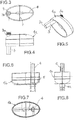
- a static mixer M can be seen to homogenize a mixture of at least two liquids.
- the mixer M comprises a closed container 1, with a top 1a, a bottom 1b, and side walls.
- the top 1a and the bottom 1b, with the associated side walls, are shell-shaped as visible on Fig. 3-8 , rotating their concavity towards each other and are assembled in an equatorial plane P, preferably by welding or by screwing.
- the container 1 is advantageously made of plastic.
- the top has two vertical legs 2 provided with a hole for a possible attachment of the container to a support.
- the mixer M comprises an inlet duct 3, vertical when the mixer M is in the working position.
- the duct 3 from above 1a and extends to the vicinity of the bottom of the container, as visible on Fig. 2 .
- the average distance between the open bottom end of the duct 3 and the bottom wall 1b is preferably less than 20 mm.
- the ducts pass through the top 1a to form a threaded connection pipe 3a.
- the mixer M further comprises an outlet duct 4, substantially parallel to the inlet duct 3, starting below and in the vicinity of the top 1a, and extending to the bottom 1b.
- the average distance between the open upper end of the duct 3 and the top wall 1a is preferably less than 20 mm.
- the duct 4 is open at the bottom, and passes through the bottom 1b to form an outlet pipe 4a advantageously provided with annular grooves for receiving a quick connection device.
- the annular grooves respectively allow the establishment of a seal and a staple for retaining a rotating nut for fixing on a threaded end.
- the inlet and outlet ducts could be horizontal between a first side wall and an opposite wall.
- the top 1a and the bottom 1b are curved so that the stream of liquid coming out of the duct 3 at the bottom reaches a curved surface 5 of the bottom 1b ( Fig. 6 which directs the flow to the opposite zone of the container.
- the container 1 has an oval horizontal section, in particular elliptical as visible on Fig. 3 and 7 , having a minor axis 7 and a major axis 8.
- the horizontal section may be circular.
- the inlet duct 3 is located in the vicinity of the container wall, and at one end of the major axis 8 of the section as visible on Fig. 3-5 .
- the lower part 3b ( Fig. 3 and 5 ) may have a U-shaped cross section open towards the wall of the container and adapted to bear against a zone, forming a belt, of the bottom 1b.
- the lower portion of the inlet duct may be in the form of a cylindrical pipe.
- the outlet duct 4 is located substantially against the inlet duct 3.
- the geometric axes of ducts 3 and 4 are located in a vertical plane which contains the major axis 8 of the horizontal section of the container.
- the output conduit may be shifted, i.e., spaced, from the input conduit.
- the container 1 is relatively flat, that is to say that its thickness in a direction orthogonal to the plane of the geometric axes of the ducts 3 and 4 is relatively small compared to its width.
- the thickness of the container 1 substantially corresponds to the dimension of the minor axis 7 of the section, while the width corresponds substantially to the size of the major axis 8.
- the ratio of the thickness of the container to its width is advantageously between 0.3 and 0.7.
- the volume of the container 1 is preferably at least three times the displacement of a reciprocating piston metering pump to which the mixer M is intended.
- a volume of 1.5 liters for the mixer M is an example of a possible value.
- the top 1a and the bottom 1b are molded separately and are assembled by arranging the upper half 1a on the lower half 1b so that the inlet duct 3 is between the outlet duct 4 and the wall near the bottom 1b.
- the assembly along the equatorial plane P is provided by any appropriate connecting means, in particular by welding or gluing.
- the mixer M is then installed in a position such that the geometric axes of the ducts 3 and 4 are vertical, the inlet pipe 3a being at the top while the outlet pipe 4a is at the bottom.
- the inlet pipe 3a is connected to an inlet pipe in which a mixture of at least two liquids circulates, and must be made more homogeneous.
- the liquid flow opens at the bottom of the conduit 3 at a reduced distance generally less than 20 mm from the bottom wall.
- the liquid stream by encountering the concave surface 5 of the bottom wall describes a curved path towards the opposite end of the container 1 and rises, by making vortices, towards the upper end of the outlet duct 4 for s'. flow through this conduit.
- the upper end of the duct 4 is located at a short distance from the upper wall of the top 1a, this distance being in particular less than 20 mm.
- Fig. 2 illustrates a dosing device D for introducing an auxiliary liquid L1 into a main liquid stream L flowing in a line C.
- the auxiliary liquid L1 is contained in a tank R from which it is taken by a metering pump 9 with a differential piston 10 with movement rectilinear alternative.
- a metering pump is known, in particular according to EP0255791
- the pump 9 has a first inlet 11 for receiving a main liquid flow which drives the pump, a second inlet 12 for withdrawing the auxiliary liquid L1 by means of a tube 13 immersed in the reservoir R and a output 14 for mixing auxiliary liquid and main liquid.
- the mixer M is arranged such that its ducts 3, 4 are vertical and the inlet connection pipe 3a is connected to the outlet 14 of the pump 9 via a pipe 15, in particular a flexible pipe.
- the outlet pipe 4a of the mixer is connected to the pipe C.
- a flow divider V having a venturi, is inserted in line C and pump 9 is connected in parallel with the flow divider.
- the first inlet 11 of the pump is connected by a first pipe 16 to the inlet of the flow divider, while the outlet 14 of the pump is connected by the pipe 15 to the mixer M whose output 4a is connected to the neck of the flow divider, constituting part of the pipe C.
- the dosing device D of Fig. 2 may further comprise variable throttling means 17 of the flow divider neck.
- a valve 18 to break a potential vacuum is advantageously provided at the connection port of the flow divider V with the outlet pipe 4a of the mixer.
- the diameter of the inlet pipe 3a is at least equivalent to the diameter of the outlet 14 of the pump.
- the volume of the container of the mixer M is at least equal to three times the displacement of the pump 9.
- the displacement corresponds to the volume displaced during a round trip of the differential piston 10.
- the mixer M can be made with two identical half-pieces 1a, turned and assembled head to tail, according to the vertical plane Q assembly.
- the mixer has an identical threaded input and output.
- the inlet is connected by a connection J to the outlet of the pump 9.
- ducts 3 and 4 are horizontal and offset.
- the mixer according to the invention while being of simple and economical production, makes it possible to obtain a homogeneous mixture of at least two liquids, in particular with a relatively small dose of auxiliary liquid, in particular less than 5% of the liquid. main.
Landscapes
- Chemical & Material Sciences (AREA)
- Chemical Kinetics & Catalysis (AREA)
- Engineering & Computer Science (AREA)
- Dispersion Chemistry (AREA)
- Mechanical Engineering (AREA)
- General Engineering & Computer Science (AREA)
- Accessories For Mixers (AREA)
- Containers And Packaging Bodies Having A Special Means To Remove Contents (AREA)
Description
- L'invention est relative à un mélangeur statique pour homogénéiser un mélange d'au moins deux liquides, en particulier après injection d'un liquide auxiliaire dans un liquide principal.
- L'injection au moyen de pompes doseuses hydrauliques d'un mélange d'eau et d'un produit liquide auxiliaire, en deux phases séparées, est connue, en particulier d'après
FR 2 967 218 - Le document
US-A-2 681 149 divulgue un appareil ayant les mêmes caractéristiques techniques que le mélangeur selon le préambule de la revendication 1. - L'invention a donc pour but de fournir un mélangeur statique de réalisation simple et économique qui permet d'obtenir une bonne homogénéisation des liquides mélangés.
- Selon l'invention, un mélangeur statique pour homogénéiser un mélange d'au moins deux liquides, en particulier après injection d'un liquide auxiliaire dans un liquide principal, est caractérisé par les caractéristiques de la revendication 1.
- La première paroi peut être formée par le dessus du récipient, et la paroi opposée formée par le fond, le conduit d'entrée étant vertical lorsque le mélangeur est en position de travail, partant du dessus et s'étendant jusqu'au voisinage du fond, tandis que le conduit de sortie débute au voisinage du dessus et s'étend jusqu'au fond.
- Selon une variante, le conduit d'entrée est horizontal, de même que le conduit de sortie.
- Avantageusement le conduit d'entrée est disposé au voisinage de la paroi latérale du récipient, en particulier contre la paroi.
- Le conduit de sortie peut être disposé à proximité du conduit d'entrée, en particulier contre le conduit d'entrée, ou en être décalé.
- Le mélangeur selon l'invention induit un écoulement tourbillonnant du mélange pour passer du conduit d'entrée au conduit de sortie, ce qui entraîne un effet d'homogénéisation élevé.
- Le conduit d'entrée peut présenter, en partie inférieure, une section transversale partiellement ouverte, la partie ouverte de cette section étant fermée pour l'essentiel par la paroi du récipient.
- Le récipient présente une section horizontale ovale, en particulier elliptique, et le conduit d'entrée est situé au voisinage d'une extrémité du grand axe de la section, tandis que le conduit de sortie est situé sensiblement contre le conduit d'entrée, du côté du centre de la section. Avantageusement, le plan des axes parallèles du conduit d'entrée et du conduit de sortie contient le grand axe de la section horizontale du mélangeur.
- Le fond et le dessus du récipient peuvent être bombés pour favoriser l'écoulement du fluide dans le mélangeur, et assurer une bonne tenue à la pression.
- De préférence, le récipient est relativement plat et présente une épaisseur, suivant une direction orthogonale au plan des axes du conduit d'entrée et du conduit de sortie, dont le rapport à la largeur du récipient est compris entre 0.3 et 0.7.
- Dans le cas ou le récipient présente une section ovale, en particulier elliptique, l'épaisseur du récipient correspond au petit axe de la section, tandis que la largeur correspond au grand axe.
- Le mélangeur peut être associé à une pompe seule. Selon une variante, le mélangeur peut être réalisé avec deux demi-pièces identiques, tournées et assemblées tête-bêche.
- L'invention est également relative à un dispositif de dosage pour introduire un liquide auxiliaire dans un courant de liquide principal, circulant dans une conduite, selon la revendication 11.
- Le dispositif de dosage peut comprendre un diviseur de débit installé dans la conduite de liquide principal, la pompe doseuse étant branchée en parallèle du diviseur de débit, la première entrée de la pompe étant reliée par une première canalisation à l'entrée du diviseur de débit tandis que la sortie de la pompe est reliée par une deuxième canalisation à un col du diviseur de débit, le mélangeur étant disposé sur la deuxième canalisation entre la sortie de la pompe et le raccord au col du diviseur de débit.
- Le dispositif de dosage peut comporter un moyen d'étranglement variable du col du diviseur de débit.
- Le volume du récipient est adapté à la pompe doseuse avec laquelle ce mélangeur est utilisé. Le volume du récipient est avantageusement égal ou supérieur a trois fois la cylindrée de la pompe doseuse.
- L'invention consiste, mises à part les dispositions exposées ci-dessus, en un certain nombre d'autres dispositions dont il sera plus explicitement question ci-après à propos d'un exemple de réalisation décrit avec référence aux dessins annexés, mais qui n'est nullement limitatif. Sur ces dessins :
-
Fig. 1 est une vue en élévation d'un mélangeur selon l'invention. -
Fig. 2 est une coupe verticale, à plus petite échelle, d'un dispositif de dosage avec pompe doseuse et mélangeur selon l'invention. -
Fig. 3 est une vue de dessous par rapport àFig. 4 . -
Fig. 4 est une vue en élévation du dessus du mélangeur. -
Fig. 5 est une vue en perspective du dessus couché sur un côté. -
Fig. 6 est une coupe verticale du dessous du mélangeur, tourné à 180° par rapport au dessus desFig. 3 et 4 . -
Fig. 7 est une vue en plan par rapport àFig. 6 . -
Fig. 8 est une vue de gauche par rapport àFig. 6 . -
Fig.9 est une coupe verticale d'une pompe sur laquelle est fixé le mélangeur, et -
Fig.10 une vue en élévation de la pompe et du mélangeur deFig. 9 . - En se reportant aux dessins, notamment à
Fig. 1 , on peut voir un mélangeur statique M pour homogénéiser un mélange d'au moins deux liquides. Le mélangeur M comporte un récipient fermé 1, avec un dessus 1a, un fond 1b, et des parois latérales. - Le dessus 1a et le fond 1b, avec les parois latérales associées, sont en forme de coque comme visible sur
Fig. 3-8 , tournant leur concavité l'un vers l'autre et sont assemblés suivant un plan équatorial P, de préférence par soudure ou par vissage. Le récipient 1 est avantageusement réalisé en matière plastique. Le dessus la comporte deux pattes verticales 2 munies d'un trou pour une fixation éventuelle du récipient à un support. - Le mélangeur M comporte un conduit d'entrée 3, vertical lorsque le mélangeur M est en position de travail. Le conduit 3 part du dessus 1a et s'étend jusqu'au voisinage du fond du récipient, comme visible sur
Fig. 2 . La distance moyenne entre l'extrémité inférieure ouverte du conduit 3 et la paroi du fond 1b est de préférence inférieure à 20 mm, Le conduits traverse le dessus 1a pour former une tubulure de raccord 3a filetée. - Le mélangeur M comporte en outre un conduit de sortie 4, sensiblement parallèle au conduit d'entrée 3, débutant au-dessous et au voisinage du dessus 1a, et s'étendant jusqu'au fond 1b. La distance moyenne entre l'extrémité supérieure ouverte du conduit 3 et la paroi du dessus 1a est de préférence inférieure à 20 mm. Le conduit 4 est ouvert vers le bas, et traverse le fond 1b pour former une tubulure de sortie 4a avantageusement munie de gorges annulaires pour recevoir un dispositif de raccordement rapide. Les gorges annulaires permettent respectivement la mise en place d'un joint et d'une agrafe pour retenir un écrou tournant assurant la fixation sur un embout fileté.
- En variante, les conduits d'entrée et de sortie pourraient être horizontaux entre une première paroi latérale et une paroi opposée.
- Le dessus 1a et le fond 1b sont bombés de sorte que le courant de liquide qui sort du conduit 3 en partie basse rencontre une surface courbe 5 du fond 1b (
Fig. 6 ) qui dirige l'écoulement vers la zone opposée du récipient. La surface concave 6 (Fig. 2 ) du dessus 1a, éloignée du conduit d'entrée 3, oriente l'écoulement vers le conduit de sortie 4. - Le récipient 1 présente une section horizontale ovale, en particulier elliptique comme visible sur
Fig. 3 et 7 , présentant un petit axe 7 et un grand axe 8. Toutefois, la section horizontale peut être circulaire. - Le conduit d'entrée 3 est situé au voisinage de la paroi du récipient, et à une extrémité du grand axe 8 de la section comme visible sur
Fig. 3-5 . La partie inférieure 3b (Fig. 3 et 5 ) peut avoir une section transversale en U ouverte vers la paroi du récipient et propre à s'appuyer contre une zone, formant une ceinture, du fond 1b. En variante, la partie inférieure du conduit d'entrée peut avoir la forme d'un tuyau cylindrique. - Le conduit de sortie 4 est situé sensiblement contre le conduit d'entrée 3. Les axes géométriques des conduits 3 et 4 sont situés dans un plan vertical qui contient le grand axe 8 de la section horizontale du récipient. En variante, le conduit de sortie peut être décalé, c'est-à-dire écarté, du conduit d'entrée.
- Le récipient 1 est relativement plat, c'est-à-dire que son épaisseur suivant une direction orthogonale au plan des axes géométriques des conduits 3 et 4 est relativement réduite par rapport à sa largeur. L'épaisseur du récipient 1 correspond sensiblement à la dimension du petit axe 7 de la section, tandis que la largeur correspond sensiblement à la dimension du grand axe 8. Le rapport de l'épaisseur du récipient à sa largeur est avantageusement compris entre 0.3 et 0.7.
- Le volume du récipient 1 est de préférence au moins égal à trois fois la cylindrée d'une pompe doseuse à piston à mouvement alternatif à laquelle serait destiné le mélangeur M. Un volume de 1.5 litre pour le mélangeur M est un exemple de valeur possible, pour une pompe de 3 m3/heure, de cylindrée 0.5 litre.
- Le dessus 1a et le fond 1b sont moulés séparément puis sont assemblés en disposant la moitié supérieure 1a sur la moitié inférieure 1b de telle manière que le conduit d'entrée 3 se trouve entre le conduit de sortie 4 et la paroi voisine du fond 1b. L'assemblage suivant le plan équatorial P est assuré par tout moyen de liaison approprié, notamment par soudure ou par collage.
- Le mélangeur M est ensuite installé dans une position telle que les axes géométriques des conduits 3 et 4 soient verticaux, la tubulure d'entrée 3a étant en partie haute tandis que la tubulure de sortie 4a est en partie basse. La tubulure d'entrée 3a est raccordée à une conduite d'arrivée dans laquelle un mélange d'au moins deux liquides circule, et doit être rendu plus homogène. Le courant de liquide débouche en partie basse du conduit 3 à une distance réduite généralement inférieure à 20 mm de la paroi du fond. Le courant de liquide en rencontrant la surface concave 5 de la paroi de fond décrit une trajectoire courbe en direction de l'extrémité opposée du récipient 1 et remonte, en effectuant des tourbillons, vers l'extrémité supérieure du conduit de sortie 4 pour s'écouler par ce conduit. L'extrémité supérieure du conduit 4 est située à faible distance de la paroi supérieure du dessus 1a, cette distance étant notamment inférieure à 20 mm.
- Les tourbillons créés dans le mélange 1 pour le passage du courant de liquide de l'extrémité inférieure du conduit 3 à l'extrémité supérieure du conduit 4, dans un volume suffisant, permettent d'homogénéiser le mélange.
-
Fig. 2 illustre un dispositif de dosage D pour introduire un liquide auxiliaire L1 dans un courant de liquide principal L circulant dans une conduite C. Le liquide auxiliaire L1 est contenu dans un réservoir R dont il est prélevé par une pompe doseuse 9 à piston différentiel 10 à mouvement rectiligne alternatif. Une telle pompe doseuse est connue, notamment d'aprèsEP0255791 - La pompe 9 comporte une première entrée 11 pour recevoir un débit de liquide principal qui assure l'entraînement de la pompe, une seconde entrée 12 pour prélever le liquide auxiliaire L1 à l'aide d'un tube 13 plongeant dans le réservoir R et une sortie 14 pour le mélange de liquide auxiliaire et de liquide principal.
- Le mélangeur M est disposé de telle sorte que ses conduits 3, 4 soient verticaux et la tubulure de raccordement d'entrée 3a est reliée à la sortie 14 de la pompe 9 par une canalisation 15, en particulier une canalisation flexible. La tubulure de sortie 4a du mélangeur est reliée à la conduite C.
- Dans l'exemple particulier illustré sur
Fig. 2 , un diviseur de débit V, comportant un venturi, est inséré dans la conduite C et la pompe 9 est branchée en parallèle du diviseur de débit. La première entrée 11 de la pompe est reliée par une première canalisation 16 à l'entrée du diviseur de débit, tandis que la sortie 14 de la pompe est reliée par la canalisation 15 au mélangeur M dont la sortie 4a est reliée au col du diviseur de débit, constituant une partie de la canalisation C. - Selon la disposition de
Fig. 2 , une fraction seulement du débit de courant principal traverse la pompe 9. Le dispositif de dosage D deFig. 2 peut en outre comporter un moyen d'étranglement variable 17 du col du diviseur de débit. - Un clapet 18 propre à casser un vide éventuel est avantageusement prévu au niveau de l'orifice de raccordement du diviseur de débit V avec la tubulure de sortie 4a du mélangeur.
- Le diamètre de la tubulure d'entrée 3a est au moins équivalent au diamètre de la sortie 14 de la pompe.
- Le volume du récipient du mélangeur M est au moins égal à trois fois la cylindrée de la pompe 9. La cylindrée correspond au volume déplacé lors d'un aller retour du piston différentiel 10.
- Selon une variante, comme illustré sur
Fig. 9 et10 , le mélangeur M peut être réalisé avec deux demi-pièces identiques 1a, tournées et assemblées tête-bêche, selon le plan vertical Q d'assemblage. Le mélangeur comporte une entrée et une sortie filetées %, identiques. L'entrée est reliée par un raccord J à la sortie de la pompe 9. Selon l'exemple deFig. 9 , les conduits 3 et 4 sont horizontaux et décalés. - Le mélangeur selon l'invention, tout en étant d'une réalisation simple et économique, permet d'obtenir un mélange homogène d'au moins deux liquides, notamment avec une dose relativement faible de liquide auxiliaire, en particulier inférieure à 5 % du liquide principal.
Claims (14)
- Mélangeur statique pour homogénéiser un mélange d'au moins deux liquides, en particulier après injection d'un liquide auxiliaire dans un liquide principal, comportant:- un récipient fermé (1) par des parois comprenant un dessus (1a), un fond (1b) et des parois latérales,- un conduit d'entrée (3), partant d'une première paroi du récipient et s'étendant jusqu'au voisinage de la paroi opposée,- et un conduit de sortie (4), sensiblement parallèle au conduit d'entrée, débutant au voisinage de la première paroi et s'étendant jusqu'à la paroi opposée,
chaque conduit étant muni d'un dispositif de raccordement (3a, 4a) à l'extérieur, à travers une paroi du récipient,
caractérisé en ce que le récipient (1) présente une section horizontale ovale, en particulier elliptique, et le conduit d'entrée (3) est situé au voisinage d'une extrémité du grand axe (8) de la section, tandis que le conduit de sortie (4) est situé sensiblement contre le conduit d'entrée, du côté du centre de la section. - Mélangeur selon la revendication 1, caractérisé en ce que la première paroi est formée par le dessus (1a) du récipient, et la paroi opposée est formée par le fond (1b), le conduit d'entrée (3) étant vertical lorsque le mélangeur est en position de travail, partant du dessus et s'étendant jusqu'au voisinage du fond, tandis que le conduit de sortie (4), débute au voisinage du dessus et s'étend jusqu'au fond.
- Mélangeur selon la revendication 2, caractérisé en ce que le conduit d'entrée (3) présente, en partie inférieure, une section transversale partiellement ouverte (3b), la partie ouverte de cette section étant fermée pour l'essentiel par la paroi du récipient.
- Mélangeur selon la revendication 1, caractérisé en ce que le conduit d'entrée est horizontal, de même que le conduit de sortie.
- Mélangeur selon l'une quelconque des revendications précédentes, caractérisé en ce que le conduit d'entrée (3) est disposé au voisinage de la paroi du récipient (1), en particulier contre la paroi.
- Mélangeur selon l'une quelconque des revendications précédentes, caractérisé en ce que le conduit de sortie (4) est disposé à proximité du conduit d'entrée (3), en particulier contre le conduit d'entrée.
- Mélangeur selon la revendication 1, caractérisé en ce que le plan des axes parallèles du conduit d'entrée (3) et du conduit de sortie (4) contient le grand axe (8) de la section horizontale du mélangeur.
- Mélangeur selon l'une quelconque des revendications précédentes, caractérisé en ce que le fond (1b) et le dessus (1a) du récipient sont bombés.
- Mélangeur selon l'une quelconque des revendications précédentes, caractérisé en ce que le récipient est relativement plat et présente une épaisseur, suivant une direction orthogonale au plan des axes du conduit d'entrée et du conduit de sortie, dont le rapport à la largeur du récipient est compris entre 0.3 et 0.7.1
- Mélangeur selon l'une quelconque des revendications précédentes, caractérisé en ce qu'il est réalisé avec deux demi-pièces identiques, tournées et assemblées tête-bêche.
- Dispositif de dosage (D) pour introduire un liquide auxiliaire (L1) dans un courant de liquide principal (L), circulant dans une conduite (C), comprenant une pompe doseuse (9) à piston différentiel à mouvement alternatif pour prélever le liquide auxiliaire dans un récipient, cette pompe comportant une première entrée (11) pour recevoir un débit de liquide principal qui assure l'entraînement de la pompe, une seconde entrée (12) pour prélever le liquide auxiliaire et une sortie (14) pour le mélange de liquide auxiliaire et de liquide principal, caractérisé en ce qu'il comporte un mélangeur statique (M), disposé à la sortie (14) de la pompe, le mélangeur statique étant destiné à homogénéiser le mélange de liquide auxiliaire et de liquide principal, et comportant:- un récipient fermé (1) par des parois comprenant un dessus (1a), un fond (1b) et des parois latérales,- un conduit d'entrée (3), partant d'une première paroi du récipient et s'étendant jusqu'au voisinage de la paroi opposée,- et un conduit de sortie (4), sensiblement parallèle au conduit d'entrée, débutant au voisinage de la première paroi et s'étendant jusqu'à la paroi opposée,
chaque conduit étant muni d'un dispositif de raccordement (3a, 4a) à l'extérieur, à travers une paroi du récipient. - Dispositif de dosage selon la revendication 11, caractérisé en ce que le mélangeur statique est en outre conforme à l'une quelconque des revendications 1 à 10.
- Dispositif de dosage selon la revendication 11 ou 12, comprenant un diviseur de débit (V) installé dans la conduite (C) de liquide principal, la pompe doseuse (9) étant branchée en parallèle du diviseur de débit, la première entrée (11) de la pompe étant reliée par une première canalisation (16) à l'entrée du diviseur de débit tandis que la sortie (14) de la pompe est reliée par une deuxième canalisation (15) à un col du diviseur de débit, caractérisé en ce que le mélangeur (M) est disposé sur la deuxième canalisation (15) entre la sortie de la pompe et le raccord au col du diviseur de débit.
- Dispositif de dosage selon la revendication 11 ou 12 ou 13, caractérisé en ce que le volume du récipient (1) est égal ou supérieur à trois fois la cylindrée de la pompe doseuse (9).
Applications Claiming Priority (2)
| Application Number | Priority Date | Filing Date | Title |
|---|---|---|---|
| FR1450195A FR3016302B1 (fr) | 2014-01-10 | 2014-01-10 | Melangeur statique pour homogeneiser un melange d'au moins deux liquides et dispositif de dosage equipe d'un tel melangeur |
| PCT/IB2015/050094 WO2015104654A1 (fr) | 2014-01-10 | 2015-01-06 | Melangeur statique pour homogeneiser un melange d'au moins deux liquides et dispositif de dosage equipe d'un tel melangeur |
Publications (2)
| Publication Number | Publication Date |
|---|---|
| EP3092064A1 EP3092064A1 (fr) | 2016-11-16 |
| EP3092064B1 true EP3092064B1 (fr) | 2019-03-27 |
Family
ID=50483114
Family Applications (1)
| Application Number | Title | Priority Date | Filing Date |
|---|---|---|---|
| EP15701249.3A Active EP3092064B1 (fr) | 2014-01-10 | 2015-01-06 | Mélangeur statique pour homogéneiser un mélange d'au moins deux liquides et dispositif de dosage équipé d'un tel mélangeur |
Country Status (13)
| Country | Link |
|---|---|
| US (1) | US10183262B2 (fr) |
| EP (1) | EP3092064B1 (fr) |
| JP (1) | JP6554119B2 (fr) |
| KR (1) | KR20160107171A (fr) |
| CN (1) | CN106102888B (fr) |
| AR (1) | AR098990A1 (fr) |
| AU (1) | AU2015205340B2 (fr) |
| ES (1) | ES2732886T3 (fr) |
| FR (1) | FR3016302B1 (fr) |
| RU (1) | RU2674960C2 (fr) |
| SG (1) | SG11201605466VA (fr) |
| TR (1) | TR201909259T4 (fr) |
| WO (1) | WO2015104654A1 (fr) |
Families Citing this family (9)
| Publication number | Priority date | Publication date | Assignee | Title |
|---|---|---|---|---|
| FR3001003B1 (fr) * | 2013-01-17 | 2015-03-20 | Dosatron International | Dispositif de dosage pour introduire un additif liquide dans un courant de liquide principal. |
| FR3016302B1 (fr) * | 2014-01-10 | 2016-02-05 | Dosatron International | Melangeur statique pour homogeneiser un melange d'au moins deux liquides et dispositif de dosage equipe d'un tel melangeur |
| MX2018005056A (es) * | 2017-07-19 | 2019-03-28 | Chapin Mfg Inc | Dispositivo de tubo venturi variable con vastago de valvula ajustable. |
| CN108675417B (zh) * | 2018-05-13 | 2021-03-02 | 九江市蓝天碧水环保有限公司 | 一种旋转扰动式的污水处理用絮凝搅拌设备的工作方法 |
| DE202018106008U1 (de) * | 2018-10-19 | 2018-11-29 | Anni Hjorth Blum | Anschlusseinrichtung für eine Acrolein-Ballastwasserbehandlungseinrichtung |
| US11596911B2 (en) * | 2020-04-07 | 2023-03-07 | Mpw Industrial Services Group, Inc. | Chemical injection system for connection to a chemical tank and a process line |
| JP2025541552A (ja) * | 2022-12-23 | 2025-12-19 | ジーイー・ベルノバ・テクノロジー・ゲーエムベーハー | 流体用静的混合器 |
| FR3154771A1 (fr) * | 2023-10-27 | 2025-05-02 | Dosatron International | Pompe a dosage proportionnel et procede de dosage associe |
| FR3156172B1 (fr) * | 2023-12-05 | 2026-05-15 | Dosatron Int | Pompe a dosage proportionnel |
Family Cites Families (18)
| Publication number | Priority date | Publication date | Assignee | Title |
|---|---|---|---|---|
| US571350A (en) * | 1896-11-17 | Henry w | ||
| US1010052A (en) * | 1910-01-12 | 1911-11-28 | J L Mott Iron Works | Liquid-mixing apparatus. |
| US1855323A (en) * | 1928-10-03 | 1932-04-26 | Charles W Sirch | Minute feed apparatus |
| US2516884A (en) * | 1948-12-08 | 1950-08-01 | George J Kyame | Method of and apparatus for preparation and distribution of sizing materials |
| US2681149A (en) * | 1949-12-01 | 1954-06-15 | Water Service Lab Inc | Liquid treating equipment |
| JPS5115265A (en) * | 1974-07-25 | 1976-02-06 | Erehon Kakoki Kk | Rainmikisaa |
| US4386634A (en) * | 1980-10-10 | 1983-06-07 | Renal Systems, Inc. | Proportioning system |
| FR2602282B1 (fr) | 1986-07-31 | 1988-09-23 | Cloup Jean | Perfectionnement aux dispositifs d'injection d'un produit additif dose dans un fluide principal |
| JP2514096Y2 (ja) * | 1990-07-06 | 1996-10-16 | デンカ生研株式会社 | 液体混合器 |
| RU2139133C1 (ru) * | 1998-06-05 | 1999-10-10 | Научно-производственное предприятие "Интэп" Товарищество с ограниченной ответственностью | Смесительное устройство для смешивания жидких или пастообразных ингредиентов в потоке жидкости |
| RU2202406C2 (ru) * | 2001-01-12 | 2003-04-20 | Баев Владимир Сергеевич | Способ приготовления водотопливной эмульсии, статическое кавитационное устройство для эмульгирования и гидродинамическое многосекционное кавитационное устройство гомогенизации эмульсии |
| FR2873172B1 (fr) * | 2004-07-15 | 2007-11-02 | Dosatron Internat Sa | Dispositif de dosage pour introduire un additif dans un courant de liquide |
| BR112012030266A2 (pt) * | 2010-05-28 | 2016-08-09 | Gea Brewery Systems Gmbh Huppman Tuchenhagen | processo para fermentação acelerada e dispositivo para mistura do conteúdo de um tanque |
| FR2967218B1 (fr) * | 2010-11-08 | 2016-09-02 | Dosatron International | Doseur proportionnel d'un liquide auxiliaire dans un liquide principal. |
| FR3001003B1 (fr) * | 2013-01-17 | 2015-03-20 | Dosatron International | Dispositif de dosage pour introduire un additif liquide dans un courant de liquide principal. |
| JP6135230B2 (ja) * | 2013-03-25 | 2017-05-31 | 株式会社ジェイ・エム・エス | 混合器 |
| FR3016302B1 (fr) * | 2014-01-10 | 2016-02-05 | Dosatron International | Melangeur statique pour homogeneiser un melange d'au moins deux liquides et dispositif de dosage equipe d'un tel melangeur |
| US10058828B2 (en) * | 2015-06-01 | 2018-08-28 | Cameron International Corporation | Apparatus for mixing of fluids flowing through a conduit |
-
2014
- 2014-01-10 FR FR1450195A patent/FR3016302B1/fr active Active
- 2014-12-29 AR ARP140104948A patent/AR098990A1/es active IP Right Grant
-
2015
- 2015-01-06 ES ES15701249T patent/ES2732886T3/es active Active
- 2015-01-06 TR TR2019/09259T patent/TR201909259T4/tr unknown
- 2015-01-06 US US15/109,880 patent/US10183262B2/en active Active
- 2015-01-06 CN CN201580003805.4A patent/CN106102888B/zh not_active Expired - Fee Related
- 2015-01-06 JP JP2016563276A patent/JP6554119B2/ja active Active
- 2015-01-06 AU AU2015205340A patent/AU2015205340B2/en not_active Ceased
- 2015-01-06 RU RU2016132754A patent/RU2674960C2/ru active
- 2015-01-06 SG SG11201605466VA patent/SG11201605466VA/en unknown
- 2015-01-06 WO PCT/IB2015/050094 patent/WO2015104654A1/fr not_active Ceased
- 2015-01-06 KR KR1020167018079A patent/KR20160107171A/ko not_active Ceased
- 2015-01-06 EP EP15701249.3A patent/EP3092064B1/fr active Active
Non-Patent Citations (1)
| Title |
|---|
| None * |
Also Published As
| Publication number | Publication date |
|---|---|
| SG11201605466VA (en) | 2016-08-30 |
| AU2015205340A1 (en) | 2016-07-21 |
| US10183262B2 (en) | 2019-01-22 |
| FR3016302A1 (fr) | 2015-07-17 |
| TR201909259T4 (tr) | 2019-07-22 |
| CN106102888A (zh) | 2016-11-09 |
| JP2017501874A (ja) | 2017-01-19 |
| AR098990A1 (es) | 2016-06-22 |
| AU2015205340B2 (en) | 2019-03-28 |
| RU2016132754A3 (fr) | 2018-07-12 |
| WO2015104654A1 (fr) | 2015-07-16 |
| ES2732886T3 (es) | 2019-11-26 |
| RU2016132754A (ru) | 2018-02-14 |
| KR20160107171A (ko) | 2016-09-13 |
| RU2674960C2 (ru) | 2018-12-13 |
| FR3016302B1 (fr) | 2016-02-05 |
| US20160325244A1 (en) | 2016-11-10 |
| CN106102888B (zh) | 2019-03-15 |
| EP3092064A1 (fr) | 2016-11-16 |
| JP6554119B2 (ja) | 2019-07-31 |
Similar Documents
| Publication | Publication Date | Title |
|---|---|---|
| FR3016302A1 (fr) | Melangeur statique pour homogeneiser un melange d'au moins deux liquides et dispositif de dosage equipe d'un tel melangeur | |
| AU2019278900B2 (en) | Apparatus in the form of a unitary, single-piece structure configured to generate and mix ultra-fine gas bubbles into a high gas concentration aqueous solution | |
| AU2023203208B2 (en) | Apparatus and method for generating and mixing ultrafine gas bubbles into a high gas concentration aqueous solution | |
| FR3032361A1 (fr) | Melangeur pour aspirer et melanger un produit solide avec un liquide provenant d’une cuve de pulverisateur | |
| US8944094B2 (en) | Adaptor for use with a valve fitment for dispensing fluids | |
| US20130336084A1 (en) | Static Mixer | |
| CN103781722B (zh) | 延迟流动挡板分送闭合件 | |
| US9604238B2 (en) | Multiple input dip tube | |
| MA43846A (fr) | Robinet de soutirage pour récipient de liquide | |
| AU2003223202A1 (en) | Stream straightener for fluid dispensing nozzle | |
| CN103201190A (zh) | 用于无菌包装的具有防流动阻塞特征的外部配件及其使用方法 | |
| CA2871908C (fr) | Douille de tube a utiliser avec une douille de robinet pour distribuer des fluides | |
| US20120298156A1 (en) | Automatic Cleaning Device for a Liquid Container | |
| FR2705038A1 (fr) | Intégrateur de liquides. | |
| US20060243749A1 (en) | Pump bottle flow control apparatus | |
| FR3053323B1 (fr) | Dispositif et procede de dosage d'un produit liquide ou pateux dans un recipient | |
| CN110899275A (zh) | 洗瓶器 | |
| FR3026001A1 (fr) | Dispositif anti-grumeaux pour biberons d'allaitement artificiel | |
| AU2018202823A1 (en) | Tap connector | |
| FR2669564A1 (fr) | Systeme de nettoyage et de desinfection d'installations et/ou de locaux. | |
| FR3054142A3 (fr) | Dispositif amovible permettant d'aerer et de verser un liquide, tel que du vin. | |
| WO2016018140A2 (fr) | Bouchon de distribution pour contenant de liquide |
Legal Events
| Date | Code | Title | Description |
|---|---|---|---|
| PUAI | Public reference made under article 153(3) epc to a published international application that has entered the european phase |
Free format text: ORIGINAL CODE: 0009012 |
|
| 17P | Request for examination filed |
Effective date: 20160701 |
|
| AK | Designated contracting states |
Kind code of ref document: A1 Designated state(s): AL AT BE BG CH CY CZ DE DK EE ES FI FR GB GR HR HU IE IS IT LI LT LU LV MC MK MT NL NO PL PT RO RS SE SI SK SM TR |
|
| AX | Request for extension of the european patent |
Extension state: BA ME |
|
| DAX | Request for extension of the european patent (deleted) | ||
| RIN1 | Information on inventor provided before grant (corrected) |
Inventor name: BADII, MANAL Inventor name: DUQUENNOY, PHILIPPE Inventor name: LAMBINET, SANDRINE |
|
| STAA | Information on the status of an ep patent application or granted ep patent |
Free format text: STATUS: EXAMINATION IS IN PROGRESS |
|
| 17Q | First examination report despatched |
Effective date: 20171024 |
|
| GRAP | Despatch of communication of intention to grant a patent |
Free format text: ORIGINAL CODE: EPIDOSNIGR1 |
|
| STAA | Information on the status of an ep patent application or granted ep patent |
Free format text: STATUS: GRANT OF PATENT IS INTENDED |
|
| INTG | Intention to grant announced |
Effective date: 20181031 |
|
| GRAS | Grant fee paid |
Free format text: ORIGINAL CODE: EPIDOSNIGR3 |
|
| GRAA | (expected) grant |
Free format text: ORIGINAL CODE: 0009210 |
|
| STAA | Information on the status of an ep patent application or granted ep patent |
Free format text: STATUS: THE PATENT HAS BEEN GRANTED |
|
| AK | Designated contracting states |
Kind code of ref document: B1 Designated state(s): AL AT BE BG CH CY CZ DE DK EE ES FI FR GB GR HR HU IE IS IT LI LT LU LV MC MK MT NL NO PL PT RO RS SE SI SK SM TR |
|
| REG | Reference to a national code |
Ref country code: GB Ref legal event code: FG4D Free format text: NOT ENGLISH |
|
| REG | Reference to a national code |
Ref country code: CH Ref legal event code: EP |
|
| REG | Reference to a national code |
Ref country code: AT Ref legal event code: REF Ref document number: 1112377 Country of ref document: AT Kind code of ref document: T Effective date: 20190415 |
|
| REG | Reference to a national code |
Ref country code: IE Ref legal event code: FG4D Free format text: LANGUAGE OF EP DOCUMENT: FRENCH |
|
| REG | Reference to a national code |
Ref country code: DE Ref legal event code: R096 Ref document number: 602015027085 Country of ref document: DE |
|
| REG | Reference to a national code |
Ref country code: NL Ref legal event code: FP |
|
| PG25 | Lapsed in a contracting state [announced via postgrant information from national office to epo] |
Ref country code: SE Free format text: LAPSE BECAUSE OF FAILURE TO SUBMIT A TRANSLATION OF THE DESCRIPTION OR TO PAY THE FEE WITHIN THE PRESCRIBED TIME-LIMIT Effective date: 20190327 Ref country code: FI Free format text: LAPSE BECAUSE OF FAILURE TO SUBMIT A TRANSLATION OF THE DESCRIPTION OR TO PAY THE FEE WITHIN THE PRESCRIBED TIME-LIMIT Effective date: 20190327 Ref country code: NO Free format text: LAPSE BECAUSE OF FAILURE TO SUBMIT A TRANSLATION OF THE DESCRIPTION OR TO PAY THE FEE WITHIN THE PRESCRIBED TIME-LIMIT Effective date: 20190627 Ref country code: LT Free format text: LAPSE BECAUSE OF FAILURE TO SUBMIT A TRANSLATION OF THE DESCRIPTION OR TO PAY THE FEE WITHIN THE PRESCRIBED TIME-LIMIT Effective date: 20190327 |
|
| PG25 | Lapsed in a contracting state [announced via postgrant information from national office to epo] |
Ref country code: BG Free format text: LAPSE BECAUSE OF FAILURE TO SUBMIT A TRANSLATION OF THE DESCRIPTION OR TO PAY THE FEE WITHIN THE PRESCRIBED TIME-LIMIT Effective date: 20190627 Ref country code: GR Free format text: LAPSE BECAUSE OF FAILURE TO SUBMIT A TRANSLATION OF THE DESCRIPTION OR TO PAY THE FEE WITHIN THE PRESCRIBED TIME-LIMIT Effective date: 20190628 Ref country code: HR Free format text: LAPSE BECAUSE OF FAILURE TO SUBMIT A TRANSLATION OF THE DESCRIPTION OR TO PAY THE FEE WITHIN THE PRESCRIBED TIME-LIMIT Effective date: 20190327 Ref country code: LV Free format text: LAPSE BECAUSE OF FAILURE TO SUBMIT A TRANSLATION OF THE DESCRIPTION OR TO PAY THE FEE WITHIN THE PRESCRIBED TIME-LIMIT Effective date: 20190327 Ref country code: RS Free format text: LAPSE BECAUSE OF FAILURE TO SUBMIT A TRANSLATION OF THE DESCRIPTION OR TO PAY THE FEE WITHIN THE PRESCRIBED TIME-LIMIT Effective date: 20190327 |
|
| REG | Reference to a national code |
Ref country code: AT Ref legal event code: MK05 Ref document number: 1112377 Country of ref document: AT Kind code of ref document: T Effective date: 20190327 |
|
| PG25 | Lapsed in a contracting state [announced via postgrant information from national office to epo] |
Ref country code: CZ Free format text: LAPSE BECAUSE OF FAILURE TO SUBMIT A TRANSLATION OF THE DESCRIPTION OR TO PAY THE FEE WITHIN THE PRESCRIBED TIME-LIMIT Effective date: 20190327 Ref country code: SK Free format text: LAPSE BECAUSE OF FAILURE TO SUBMIT A TRANSLATION OF THE DESCRIPTION OR TO PAY THE FEE WITHIN THE PRESCRIBED TIME-LIMIT Effective date: 20190327 Ref country code: RO Free format text: LAPSE BECAUSE OF FAILURE TO SUBMIT A TRANSLATION OF THE DESCRIPTION OR TO PAY THE FEE WITHIN THE PRESCRIBED TIME-LIMIT Effective date: 20190327 Ref country code: EE Free format text: LAPSE BECAUSE OF FAILURE TO SUBMIT A TRANSLATION OF THE DESCRIPTION OR TO PAY THE FEE WITHIN THE PRESCRIBED TIME-LIMIT Effective date: 20190327 Ref country code: PT Free format text: LAPSE BECAUSE OF FAILURE TO SUBMIT A TRANSLATION OF THE DESCRIPTION OR TO PAY THE FEE WITHIN THE PRESCRIBED TIME-LIMIT Effective date: 20190727 Ref country code: AL Free format text: LAPSE BECAUSE OF FAILURE TO SUBMIT A TRANSLATION OF THE DESCRIPTION OR TO PAY THE FEE WITHIN THE PRESCRIBED TIME-LIMIT Effective date: 20190327 |
|
| REG | Reference to a national code |
Ref country code: ES Ref legal event code: FG2A Ref document number: 2732886 Country of ref document: ES Kind code of ref document: T3 Effective date: 20191126 |
|
| PG25 | Lapsed in a contracting state [announced via postgrant information from national office to epo] |
Ref country code: PL Free format text: LAPSE BECAUSE OF FAILURE TO SUBMIT A TRANSLATION OF THE DESCRIPTION OR TO PAY THE FEE WITHIN THE PRESCRIBED TIME-LIMIT Effective date: 20190327 Ref country code: SM Free format text: LAPSE BECAUSE OF FAILURE TO SUBMIT A TRANSLATION OF THE DESCRIPTION OR TO PAY THE FEE WITHIN THE PRESCRIBED TIME-LIMIT Effective date: 20190327 |
|
| PG25 | Lapsed in a contracting state [announced via postgrant information from national office to epo] |
Ref country code: AT Free format text: LAPSE BECAUSE OF FAILURE TO SUBMIT A TRANSLATION OF THE DESCRIPTION OR TO PAY THE FEE WITHIN THE PRESCRIBED TIME-LIMIT Effective date: 20190327 Ref country code: IS Free format text: LAPSE BECAUSE OF FAILURE TO SUBMIT A TRANSLATION OF THE DESCRIPTION OR TO PAY THE FEE WITHIN THE PRESCRIBED TIME-LIMIT Effective date: 20190727 |
|
| REG | Reference to a national code |
Ref country code: DE Ref legal event code: R097 Ref document number: 602015027085 Country of ref document: DE |
|
| PG25 | Lapsed in a contracting state [announced via postgrant information from national office to epo] |
Ref country code: DK Free format text: LAPSE BECAUSE OF FAILURE TO SUBMIT A TRANSLATION OF THE DESCRIPTION OR TO PAY THE FEE WITHIN THE PRESCRIBED TIME-LIMIT Effective date: 20190327 |
|
| PLBE | No opposition filed within time limit |
Free format text: ORIGINAL CODE: 0009261 |
|
| STAA | Information on the status of an ep patent application or granted ep patent |
Free format text: STATUS: NO OPPOSITION FILED WITHIN TIME LIMIT |
|
| PG25 | Lapsed in a contracting state [announced via postgrant information from national office to epo] |
Ref country code: SI Free format text: LAPSE BECAUSE OF FAILURE TO SUBMIT A TRANSLATION OF THE DESCRIPTION OR TO PAY THE FEE WITHIN THE PRESCRIBED TIME-LIMIT Effective date: 20190327 |
|
| 26N | No opposition filed |
Effective date: 20200103 |
|
| PG25 | Lapsed in a contracting state [announced via postgrant information from national office to epo] |
Ref country code: MC Free format text: LAPSE BECAUSE OF FAILURE TO SUBMIT A TRANSLATION OF THE DESCRIPTION OR TO PAY THE FEE WITHIN THE PRESCRIBED TIME-LIMIT Effective date: 20190327 |
|
| REG | Reference to a national code |
Ref country code: CH Ref legal event code: PL |
|
| PG25 | Lapsed in a contracting state [announced via postgrant information from national office to epo] |
Ref country code: LU Free format text: LAPSE BECAUSE OF NON-PAYMENT OF DUE FEES Effective date: 20200106 |
|
| PG25 | Lapsed in a contracting state [announced via postgrant information from national office to epo] |
Ref country code: CH Free format text: LAPSE BECAUSE OF NON-PAYMENT OF DUE FEES Effective date: 20200131 Ref country code: LI Free format text: LAPSE BECAUSE OF NON-PAYMENT OF DUE FEES Effective date: 20200131 |
|
| PG25 | Lapsed in a contracting state [announced via postgrant information from national office to epo] |
Ref country code: IE Free format text: LAPSE BECAUSE OF NON-PAYMENT OF DUE FEES Effective date: 20200106 |
|
| PGFP | Annual fee paid to national office [announced via postgrant information from national office to epo] |
Ref country code: NL Payment date: 20210120 Year of fee payment: 7 |
|
| PGFP | Annual fee paid to national office [announced via postgrant information from national office to epo] |
Ref country code: BE Payment date: 20210120 Year of fee payment: 7 Ref country code: ES Payment date: 20210326 Year of fee payment: 7 |
|
| REG | Reference to a national code |
Ref country code: DE Ref legal event code: R079 Ref document number: 602015027085 Country of ref document: DE Free format text: PREVIOUS MAIN CLASS: B01F0003080000 Ipc: B01F0023400000 |
|
| PG25 | Lapsed in a contracting state [announced via postgrant information from national office to epo] |
Ref country code: MT Free format text: LAPSE BECAUSE OF FAILURE TO SUBMIT A TRANSLATION OF THE DESCRIPTION OR TO PAY THE FEE WITHIN THE PRESCRIBED TIME-LIMIT Effective date: 20190327 Ref country code: CY Free format text: LAPSE BECAUSE OF FAILURE TO SUBMIT A TRANSLATION OF THE DESCRIPTION OR TO PAY THE FEE WITHIN THE PRESCRIBED TIME-LIMIT Effective date: 20190327 |
|
| PG25 | Lapsed in a contracting state [announced via postgrant information from national office to epo] |
Ref country code: MK Free format text: LAPSE BECAUSE OF FAILURE TO SUBMIT A TRANSLATION OF THE DESCRIPTION OR TO PAY THE FEE WITHIN THE PRESCRIBED TIME-LIMIT Effective date: 20190327 |
|
| REG | Reference to a national code |
Ref country code: NL Ref legal event code: MM Effective date: 20220201 |
|
| REG | Reference to a national code |
Ref country code: BE Ref legal event code: MM Effective date: 20220131 |
|
| PG25 | Lapsed in a contracting state [announced via postgrant information from national office to epo] |
Ref country code: NL Free format text: LAPSE BECAUSE OF NON-PAYMENT OF DUE FEES Effective date: 20220201 |
|
| PG25 | Lapsed in a contracting state [announced via postgrant information from national office to epo] |
Ref country code: BE Free format text: LAPSE BECAUSE OF NON-PAYMENT OF DUE FEES Effective date: 20220131 |
|
| REG | Reference to a national code |
Ref country code: ES Ref legal event code: FD2A Effective date: 20230306 |
|
| PG25 | Lapsed in a contracting state [announced via postgrant information from national office to epo] |
Ref country code: ES Free format text: LAPSE BECAUSE OF NON-PAYMENT OF DUE FEES Effective date: 20220107 |
|
| P01 | Opt-out of the competence of the unified patent court (upc) registered |
Effective date: 20230523 |
|
| PG25 | Lapsed in a contracting state [announced via postgrant information from national office to epo] |
Ref country code: TR Free format text: LAPSE BECAUSE OF NON-PAYMENT OF DUE FEES Effective date: 20200106 |
|
| PGFP | Annual fee paid to national office [announced via postgrant information from national office to epo] |
Ref country code: GB Payment date: 20260130 Year of fee payment: 12 |
|
| PGFP | Annual fee paid to national office [announced via postgrant information from national office to epo] |
Ref country code: DE Payment date: 20260129 Year of fee payment: 12 |
|
| PGFP | Annual fee paid to national office [announced via postgrant information from national office to epo] |
Ref country code: IT Payment date: 20260128 Year of fee payment: 12 |
|
| PGFP | Annual fee paid to national office [announced via postgrant information from national office to epo] |
Ref country code: FR Payment date: 20260127 Year of fee payment: 12 |