EP3092115B1 - Ventilnadel und düsenanordnung sowie verfahren zur steuerung - Google Patents
Ventilnadel und düsenanordnung sowie verfahren zur steuerung Download PDFInfo
- Publication number
- EP3092115B1 EP3092115B1 EP15700932.5A EP15700932A EP3092115B1 EP 3092115 B1 EP3092115 B1 EP 3092115B1 EP 15700932 A EP15700932 A EP 15700932A EP 3092115 B1 EP3092115 B1 EP 3092115B1
- Authority
- EP
- European Patent Office
- Prior art keywords
- gate
- valve pin
- upstream
- downstream
- fluid
- Prior art date
- Legal status (The legal status is an assumption and is not a legal conclusion. Google has not performed a legal analysis and makes no representation as to the accuracy of the status listed.)
- Active
Links
- 238000000034 method Methods 0.000 title claims description 4
- 238000011144 upstream manufacturing Methods 0.000 claims description 65
- 238000002347 injection Methods 0.000 claims description 54
- 239000007924 injection Substances 0.000 claims description 54
- 239000012530 fluid Substances 0.000 claims description 52
- 238000009413 insulation Methods 0.000 claims description 27
- 230000000295 complement effect Effects 0.000 claims description 11
- 238000001746 injection moulding Methods 0.000 claims description 11
- 238000004891 communication Methods 0.000 claims description 2
- 239000000463 material Substances 0.000 description 11
- 230000007547 defect Effects 0.000 description 5
- 230000000007 visual effect Effects 0.000 description 5
- 239000004020 conductor Substances 0.000 description 1
- 230000001419 dependent effect Effects 0.000 description 1
- 238000001514 detection method Methods 0.000 description 1
- 239000007788 liquid Substances 0.000 description 1
- 239000000289 melt material Substances 0.000 description 1
- 239000012768 molten material Substances 0.000 description 1
- 230000002265 prevention Effects 0.000 description 1
- 238000009877 rendering Methods 0.000 description 1
- 238000007789 sealing Methods 0.000 description 1
- 239000007787 solid Substances 0.000 description 1
- XLYOFNOQVPJJNP-UHFFFAOYSA-N water Substances O XLYOFNOQVPJJNP-UHFFFAOYSA-N 0.000 description 1
Images


Classifications
-
- B—PERFORMING OPERATIONS; TRANSPORTING
- B29—WORKING OF PLASTICS; WORKING OF SUBSTANCES IN A PLASTIC STATE IN GENERAL
- B29C—SHAPING OR JOINING OF PLASTICS; SHAPING OF MATERIAL IN A PLASTIC STATE, NOT OTHERWISE PROVIDED FOR; AFTER-TREATMENT OF THE SHAPED PRODUCTS, e.g. REPAIRING
- B29C45/00—Injection moulding, i.e. forcing the required volume of moulding material through a nozzle into a closed mould; Apparatus therefor
- B29C45/17—Component parts, details or accessories; Auxiliary operations
- B29C45/26—Moulds
- B29C45/27—Sprue channels ; Runner channels or runner nozzles
- B29C45/278—Nozzle tips
-
- B—PERFORMING OPERATIONS; TRANSPORTING
- B29—WORKING OF PLASTICS; WORKING OF SUBSTANCES IN A PLASTIC STATE IN GENERAL
- B29C—SHAPING OR JOINING OF PLASTICS; SHAPING OF MATERIAL IN A PLASTIC STATE, NOT OTHERWISE PROVIDED FOR; AFTER-TREATMENT OF THE SHAPED PRODUCTS, e.g. REPAIRING
- B29C45/00—Injection moulding, i.e. forcing the required volume of moulding material through a nozzle into a closed mould; Apparatus therefor
- B29C45/17—Component parts, details or accessories; Auxiliary operations
- B29C45/26—Moulds
- B29C45/27—Sprue channels ; Runner channels or runner nozzles
-
- B—PERFORMING OPERATIONS; TRANSPORTING
- B29—WORKING OF PLASTICS; WORKING OF SUBSTANCES IN A PLASTIC STATE IN GENERAL
- B29C—SHAPING OR JOINING OF PLASTICS; SHAPING OF MATERIAL IN A PLASTIC STATE, NOT OTHERWISE PROVIDED FOR; AFTER-TREATMENT OF THE SHAPED PRODUCTS, e.g. REPAIRING
- B29C45/00—Injection moulding, i.e. forcing the required volume of moulding material through a nozzle into a closed mould; Apparatus therefor
- B29C45/17—Component parts, details or accessories; Auxiliary operations
- B29C45/26—Moulds
- B29C45/27—Sprue channels ; Runner channels or runner nozzles
- B29C45/28—Closure devices therefor
- B29C45/2806—Closure devices therefor consisting of needle valve systems
-
- B—PERFORMING OPERATIONS; TRANSPORTING
- B29—WORKING OF PLASTICS; WORKING OF SUBSTANCES IN A PLASTIC STATE IN GENERAL
- B29C—SHAPING OR JOINING OF PLASTICS; SHAPING OF MATERIAL IN A PLASTIC STATE, NOT OTHERWISE PROVIDED FOR; AFTER-TREATMENT OF THE SHAPED PRODUCTS, e.g. REPAIRING
- B29C45/00—Injection moulding, i.e. forcing the required volume of moulding material through a nozzle into a closed mould; Apparatus therefor
- B29C45/17—Component parts, details or accessories; Auxiliary operations
- B29C45/26—Moulds
- B29C45/27—Sprue channels ; Runner channels or runner nozzles
- B29C2045/2761—Seals between nozzle and mould or gate
-
- B—PERFORMING OPERATIONS; TRANSPORTING
- B29—WORKING OF PLASTICS; WORKING OF SUBSTANCES IN A PLASTIC STATE IN GENERAL
- B29C—SHAPING OR JOINING OF PLASTICS; SHAPING OF MATERIAL IN A PLASTIC STATE, NOT OTHERWISE PROVIDED FOR; AFTER-TREATMENT OF THE SHAPED PRODUCTS, e.g. REPAIRING
- B29C45/00—Injection moulding, i.e. forcing the required volume of moulding material through a nozzle into a closed mould; Apparatus therefor
- B29C45/17—Component parts, details or accessories; Auxiliary operations
- B29C45/26—Moulds
- B29C45/27—Sprue channels ; Runner channels or runner nozzles
- B29C2045/2766—Heat insulation between nozzle and mould
- B29C2045/2767—Heat insulation between nozzle and mould the heat insulation being provided with an axial opening being part of the melt flow channel
-
- B—PERFORMING OPERATIONS; TRANSPORTING
- B29—WORKING OF PLASTICS; WORKING OF SUBSTANCES IN A PLASTIC STATE IN GENERAL
- B29C—SHAPING OR JOINING OF PLASTICS; SHAPING OF MATERIAL IN A PLASTIC STATE, NOT OTHERWISE PROVIDED FOR; AFTER-TREATMENT OF THE SHAPED PRODUCTS, e.g. REPAIRING
- B29C45/00—Injection moulding, i.e. forcing the required volume of moulding material through a nozzle into a closed mould; Apparatus therefor
- B29C45/17—Component parts, details or accessories; Auxiliary operations
- B29C45/26—Moulds
- B29C45/27—Sprue channels ; Runner channels or runner nozzles
- B29C45/278—Nozzle tips
- B29C2045/2787—Nozzle tips made of at least 2 different materials
-
- B—PERFORMING OPERATIONS; TRANSPORTING
- B29—WORKING OF PLASTICS; WORKING OF SUBSTANCES IN A PLASTIC STATE IN GENERAL
- B29C—SHAPING OR JOINING OF PLASTICS; SHAPING OF MATERIAL IN A PLASTIC STATE, NOT OTHERWISE PROVIDED FOR; AFTER-TREATMENT OF THE SHAPED PRODUCTS, e.g. REPAIRING
- B29C45/00—Injection moulding, i.e. forcing the required volume of moulding material through a nozzle into a closed mould; Apparatus therefor
- B29C45/17—Component parts, details or accessories; Auxiliary operations
- B29C45/26—Moulds
- B29C45/27—Sprue channels ; Runner channels or runner nozzles
- B29C45/28—Closure devices therefor
- B29C45/2806—Closure devices therefor consisting of needle valve systems
- B29C2045/2879—Back flow of material into nozzle channel
-
- B—PERFORMING OPERATIONS; TRANSPORTING
- B29—WORKING OF PLASTICS; WORKING OF SUBSTANCES IN A PLASTIC STATE IN GENERAL
- B29C—SHAPING OR JOINING OF PLASTICS; SHAPING OF MATERIAL IN A PLASTIC STATE, NOT OTHERWISE PROVIDED FOR; AFTER-TREATMENT OF THE SHAPED PRODUCTS, e.g. REPAIRING
- B29C2945/00—Indexing scheme relating to injection moulding, i.e. forcing the required volume of moulding material through a nozzle into a closed mould
- B29C2945/76—Measuring, controlling or regulating
- B29C2945/76494—Controlled parameter
- B29C2945/76568—Position
-
- B—PERFORMING OPERATIONS; TRANSPORTING
- B29—WORKING OF PLASTICS; WORKING OF SUBSTANCES IN A PLASTIC STATE IN GENERAL
- B29C—SHAPING OR JOINING OF PLASTICS; SHAPING OF MATERIAL IN A PLASTIC STATE, NOT OTHERWISE PROVIDED FOR; AFTER-TREATMENT OF THE SHAPED PRODUCTS, e.g. REPAIRING
- B29C45/00—Injection moulding, i.e. forcing the required volume of moulding material through a nozzle into a closed mould; Apparatus therefor
- B29C45/03—Injection moulding apparatus
-
- B—PERFORMING OPERATIONS; TRANSPORTING
- B29—WORKING OF PLASTICS; WORKING OF SUBSTANCES IN A PLASTIC STATE IN GENERAL
- B29C—SHAPING OR JOINING OF PLASTICS; SHAPING OF MATERIAL IN A PLASTIC STATE, NOT OTHERWISE PROVIDED FOR; AFTER-TREATMENT OF THE SHAPED PRODUCTS, e.g. REPAIRING
- B29C45/00—Injection moulding, i.e. forcing the required volume of moulding material through a nozzle into a closed mould; Apparatus therefor
- B29C45/17—Component parts, details or accessories; Auxiliary operations
- B29C45/76—Measuring, controlling or regulating
- B29C45/7613—Measuring, controlling or regulating the termination of flow of material into the mould
Definitions
- valve pins such as disclosed in PCT/CA2012/050002 and in U.S. Published Application 201/0045537 and in PCT/US2012/0366106 having cylindrical or conical geometries have been used in injection molding systems where withdrawal and closure of the pins have been controlled in an attempt to reduce vestiges on parts produced.
- an injection molding apparatus 10 in accordance with claim 1.
- an axially interior surface 64s of the fluid exit aperture 64 of the insulation cap 60 surrounds the gap enabling circumferential surface 92 of the valve pin forming a spatial gap 60g immediately upstream of the gate 85 between the interior surface 64s of the fluid exit aperture 64 of the insulation cap 60 and the gap enabling circumferential surface 92 of the valve pin 90.
- the actuator can be interconnected to a controller (16) that controllably instructs the actuator (941) to drive the distal end portion (90d, 97) of the valve pin continuously upstream starting from the gate closed position (P4) at one or more intermediate upstream velocities that are less than a predetermined high velocity and to subsequently further drive the valve pin upstream at the predetermined high velocity.
- the actuator comprises a hydraulically driven or pneumatically driven actuator.
- the actuator can comprise an electrically powered motor.
- the spatial gap is typically adapted to receive injection fluid that is forced upstream from the gate when the valve pin is moved downstream toward the gate closed position.
- the axially interior surface of the gate typically comprises a surface of the mold.
- the nozzle channel can have an axially interior surface disposed upstream of the fluid exit apertures that is complementary to and slidably engages with the gap enabling circumferential surface of the valve pin to align the axis of the valve pin with the gate during downstream movement of the valve pin toward the gate closed position.
- An axially inner surface of an upstream end portion of the insulation cap is typically engaged against an axially outer surface of a downstream end of the insert, the upstream end portion of the insulation cap being compressed between the insert and an axially inner surface of the distal tip of the nozzle to seal flow of the injection fluid to within the nozzle channel.
- the distal end portion of the valve pin is preferably configured such that flow of injection fluid through the gate is restricted at one or more positions of the valve pin that are intermediate the gate closed position and a fully upstream gate open position at which flow of the injection fluid is unrestricted.
- the upstream circumferential surface of the distal end portion of the valve pin preferably slidably engages with an axially interior surface of the nozzle flow channel to align the axis of the pin with the gate during downstream movement of the pin toward the gate closed position.
- the actuator can comprise a hydraulically driven or pneumatically driven actuator or an electrically powered motor.
- the actuator is typically interconnected to a controller that controllably instructs the actuator to drive the distal end portion of the valve pin continuously upstream starting from the gate closed position at one or more intermediate upstream velocities that are less than a predetermined high velocity and to subsequently further drive the valve pin upstream at the predetermined high velocity.
- the insulation cap is typically configured to form a circumferential gap around a portion of the circumferential surface of the pin that is disposed immediately upstream of the first internal surface of the flow channel when the secondary portion of circumferential surface of the valve pin is contact with the first internal surface of the flow channel.
- the first internal channel surface surrounding the gate preferably comprises a surface of the mold.
- the pin preferably has a tertiary portion of its circumferential surface that is upstream of the secondary portion that slidably engages with a second internal surface of the flow channel to align the axis of the pin with the gate during downstream movement of the pin toward the gate closed position.
- the second internal surface of the flow channel is typically disposed immediately upstream of the insulation cap, the insulation cap being configured to form a circumferential gap around a portion of the circumferential surface of the pin that is disposed immediately upstream of the first internal surface of the flow channel when the secondary portion of the circumferential surface of the valve pin is contact with the first internal surface of the flow channel.
- An inner surface of an upstream end portion of the insulation cap is preferably engaged against an outer surface of a downstream end of the insert, the upstream end portion of the insulation cap being compressed between the insert and an inner surface of the distal tip of the nozzle to seal flow of the injection fluid to within the flow channel.
- the distal tip end of the valve pin can have an outer circumferential edge that is sharpened.
- the distal tip end of the valve pin can have an outer circumferential edge that is rounded or curved.
- the actuator can be hydraulic, pneumatic or electrically powered.
- the actuator is preferably driven by a valve system that is controllably adjustable between a start position that positions the distal tip end of the valve pin in the gate closed position, one or more intermediate drive rate positions that drive the valve pin upstream from the gate closed position through one or more intermediate upstream positions at one or more corresponding intermediate velocities and a high drive rate position that drives the valve pin at a high velocity that is higher than the intermediate velocities.
- a valve system that is controllably adjustable between a start position that positions the distal tip end of the valve pin in the gate closed position, one or more intermediate drive rate positions that drive the valve pin upstream from the gate closed position through one or more intermediate upstream positions at one or more corresponding intermediate velocities and a high drive rate position that drives the valve pin at a high velocity that is higher than the intermediate velocities.
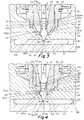
- Fig. 1 shows a prior art valve configuration having a nozzle insert IN and an insulation cap IC with a valve pin having a configuration where the distal tip end portion of the valve pin, when driven into the gate closed position as shown provides no relief or escape from the high pressure of injection fluid that is being forced into the mold cavity during the course of movement of the valve pin from an upstream position downstream into a gate closed position.
- Fig. 2 shows one system embodiment 10 of the invention comprised of an injection machine 20 that feeds meltable injection material that is converted from solid form into molten or liquid flowing material form within the barrel (not shown) of the machine 20 by a screw (not shown) that drives the molten material 32 downstream under a controlled pressure into the fluid distribution channels 35 of a hotrunner or manifold 30.
- the molten fluid 32 is driven from the manifold channel 35 into the upstream end 52, Figs. 3, 4 of a central flow passage or channel 54 of a nozzle 50.
- the nozzle 50 is mounted within an aperture 83 provided within the mold body 88 or an intermediate plate that is mounted to the mold plate 88.
- the melt material 32 further flows downstream under pressure through a continuous flow channel 54, 54a, 64, 74 that extends from the upstream end 52 of the nozzle to a gate 85 of a mold cavity 80, the continuous flow channel 54, 54a, 64, 74 being collectively comprised of the upper nozzle channel 54, Figs.
- downstream channel 54a that is disposed within a nozzle insert 55 which further communicates with a channel 64 that is formed within an insulation cap 60 that in turn sealably communicates with a downstream channel 74 formed within the body of the mold 88, the channel 74 communicating at its downstream end with the gate 85 to the cavity 80 of the mold 88.
- the nozzle 50 itself is comprised of an outermost cylindrical nozzle tube or body 53 having a central flow channel 54, a cylindrical nozzle tip 56 that is typically screwably engaged concentrically within the downstream distal end of the outer body 53 of the nozzle 50, a cylindrical nozzle insert 55 having a flow channel 54a that is concentrically mounted within the interior circumference of the tip 56 and a cylindical insulation cap 60 having a flow bore or exit aperture 64 that is concentrically mounted between the axially outer circumferential surface of the insert 55 and the distal-most portion of the axially inner circumferential surface of the nozzle tip 56.
- the system includes a valve pin 90 interconnected at an upstream end to an actuator 941 in a conventional manner (not shown) as described and shown in, for example, U.S. Patent Application Publication No. 2012/0248644 or U.S. Patent Application Publication No. 2012/0248652 such that the actuator 941 and pin 90 move reciprocally upstream and downstream A in unison along an axial path A through the flow channel 54, 54a, 64, 74.
- the actuator 941 is interconnected to a controller 16 that contains an algorithm that controls the upstream-downstream velocity of movement of the pin 90 and actuator 941 along axis A between a fully gate closed, Fig. 4 , and a fully upstream position.
- the actuator 941 can comprise a fluid driven mechanism such as a hydraulically or pneumatically driven actuator as described in for example U.S. patent nos. 5894025 , 6464909 , 6585505 , 8016581 , 7597828 .
- the actuator 941 can comprise an electrically driven motor, the shaft of which is interconnected to the valve pin as disclosed for example in U.S. Patent No. 6,194,122 the disclosure of which is incorporated herein by reference as if fully set forth herein.
- the controller 16 can be adapted to controllably drive any of the hydraulic, pneumatic or electric motor actuators referenced above in order to drive the valve pin along any path of travel during the course of an injection cycle according any predetermined program, algorithm or protocol.
- the outer circumferential surface 57 of the nozzle tip 56 forms a fluid seal around the gate 85 by compressed engagement with an inner circumferential surface 86 of the mold 88 thus sealing injection fluid within the central flow channel 54, 54a, 64, 74 and preventing injection fluid from seeping into the cavity or aperture 83 in which the nozzle 50 is mounted. Additionally, the outer surface 60s of the insulation cap 60 is in compressed contact with the axially inner surface 81s of the receiving or mounting aperture 81 forming a fluid seal S around the gate 85 that seals and prevents injection fluid 32 from seeping into the cavity or aperture 83 in which the nozzle 50 is mounted.
- the nozzle body 53 is typically heated to an elevated temperature so as to maintain the injection fluid material at an elevated ready flow facilitated temperature.
- the insert 55 is typically mounted concentrically within the nozzle tip 56 in thermal communication with the nozzle body 53 and tip 56 and is thus in turn heated and is preferably comprised of a highly heat conductive material so as to remain heated together with the nozzle body 53 and tip 56 to maintain the injection fluid material flowing through channel 54, 54a, 64, 74 at a high flow ready temperature at or near the entry to the gate 85.
- the insulation cap 60 is comprised of a non heat conductive or heat insulative material.
- the mold body 88 is cooled with water during an injection cycle and is maintained at a relatively low or cooled temperature relative to the very high temperature of the nozzle 50 and its associated components 53, 55, 56.
- the insulation cap 60 is mounted immediately downstream of the highly conductive insert 55 between the insert 55 and any opposing interior surface of the mold body 88 which is cool or cooled relative to the very high temperature of the nozzle 50 and its components 53, 55, 56.
- the insulation cap 60 thus insulates heat transfer or loss between the nozzle 50 and the mold 88.
- the geometry or configuration of the insulation cap 60, the insert 55 and the receiving cavity or aperture 81 of the mold 88 within which the cap 60 is mounted are all adapted and configured such that an interior surface 63 of the cap 60 receives and engages a major portion of the exterior circumferential surface 55es of the highly conductive insert 55 thus facilitating and effecting prevention of heat transfer or thermal insulation between the insert 55 and the mold 88.
- Fig. 2 shows the system at a point in time in an injection cycle where the valve pin 90 is disposed in an upstream, gate open position where injection fluid flow through the channel 54, 54a, 64, 74 is not restricted by the distance between an exterior circumferential surface of the pin 90 and an interior surface of the channel 54, 54a, 64, 74.
- Fig. 3 shows the system at a point in time in an injection cycle where the pin 90 has moved downstream nearer the gate 85 relative to the position of the pin 90 in Fig. 2 .
- the pin 90 has a distally disposed bulbous protrusion 90p that has a distally disposed portion of its exterior circumferential surface 92 that is formed and configured to be complementary in geometry, diameter and the like to the geometry, diameter and configuration of a complementary axially interior surface 55gs of the insert 55, the surface 55gs being formed to be complementary to the surface 92 and to slidably receive and engage surface 92 as the pin 90 axially moves A such that the axis A of the pin is guided in its movement in alignment with the gate 85 and with the flow channel 54, 54a, 64, 74 generally.
- Fig. 4 shows the system 10 at a point in time in an injection cycle where the pin surface 92 is immediately upstream of being received by and slidably engaging against the guide surface 55gs of the insert.
- a small gap FG is formed between the axially interior surface 55s, Fig. 4 , where the rate of flow of injection fluid 32r is reduced relative to the rate of flow when the pin is in the positions P1 and P2 of Figs. 2 , 3 respectively.
- Such a reduced flow rate 32r occurs over some length of pin travel PT1 and PT2 when the circumferential surface 92 is closely adjacent, either upstream (PT1) or downstream (PT2) to or of the guide surface 55gs.
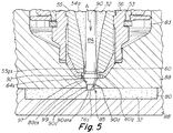
- Fig. 5 shows the system and the position of the pin P4 at a point in time when the pin 90 has been driven to it furthest downstream position whereby the gate 85 to the mold cavity 80 has been closed and flow of molten injection material through the channel 54, 54a, 64, 74 is stopped.
- the mold body 88 is formed having a receiving cavity or channel 74 that has an interior surface 88cs that is complementary in geometry and configuration to the preselected geometry and configuration of a distally disposed end portion of the exterior circumferential surface 97 of the pin 90.
- the surface 88cs is configured such that when the pin 90 is driven to its furthest downstream position shown in Fig. 5 , the complementary surface 97 of the pin engages with surface 88cs to force all injection fluid material that resides in the distal portion 74 of the flow channel through the gate 85.
- the distal-most portion 90d of the pin 90 has a cylindrically shaped outer circumferential surface 99 that is complementary to an inner surface 76s of the distal-most space 76 that is immediately downstream of the flow channel 54, 54a, 64, 74 such that when the pin 90 is driven to its fully gate closed position as shown in Fig. 4 , the circumferential surface 99 of portion 90d will slidably engage against surface 76s and the distal tip end surface 90dte of the pin 90 will force all injection fluid material that resides in the distal-most portion 76 of the flow channel through the gate 85.
- the distal-most edges or corners 90c of the distal-most portion 90d of the pin 90 are preferably sharpened such that the outer surfaces of portion 90d that mate to form the edges or corners 90c are either flat or concave.
- the bottom surface 90dte of pin 90 can be convex or have a slight outward radius rendering the corners 90c rounded or curved.
- the insulation cap 60 can be adapted, formed or configured to form a sealed or enclosed circumferential gap or space 60g that surrounds the circumferential surface of the valve pin that is immediately upstream of the gate 95.
- a space 60g serves to receive upstream backflow of injection fluid that is forced into space 76 that does not readily flow through gate 85 during the course of driven downstream movement of the pin 90 into a fully gate closed position and the movement of tip end member 90d into space 76, the circumferential gap or space 60g also serving to relieve excess pressure in the injection fluid in the immediate area of the gate 85 during the course of such closure of the pin 90, such relief of excess pressure minimizing or preventing the occurrence of a visual defect or artifact in the final cooled part produced within the cavity 80.
- the gap 60g is formed between the axially interior surface 64s and the circumferential surface 92 of the bulbous protrusion portion 92p of the valve pin 90.
- valve pin 90 is interconnected to an actuator 941, the operation of which is controlled by an electronic controller 16 that contains an algorithm that controllably drives the valve pin 90 to selectable axial positions or at selectable velocities along the axis A of the flow channel 54, 54a, 64, 74.
- the system can include a position sensor 951 that detects axial position of the pin or the actuator and sends the position signal to the controller 16 which uses the position signal to cause the pin 90 to be driven to selected positions or at preselected velocities either upstream or downstream depending on the detected position of the pin 90.
- the velocity of the pin is typically withdrawn beginning from a gate closed position to a predetermined upstream position at a relatively low velocity that prevents fluid injection material from flowing through the gate 85 into the cavity 80 at a rate that will result in a visual defect, vestige or artifact occurring in the part that is ultimately produced in the mold cavity 80.
- the algorithm can be programmed to cause the valve pin 90 to be withdrawn upstream at a high velocity that is higher than the initial lower velocity (typically the maximum velocity at which the hydraulic, pneumatic or electric motor drive system is capable of driving the pin) when the axial position of the pin 90 or actuator 941 has been determined by the position sensor 951 to have reached an intermediate upstream position at which the valve pin 90 does not restrict the flow of injection fluid through the gate 85.
- the valve pin 90 is driven continuously upstream from the gate closed position (shown in Fig. 5 ) to a fully upstream gate open position during the upstream withdrawal portion of an injection cycle.
- valve pin 90 or actuator 941 can also be controllably driven from an upstream position to the gate closed position, Fig. 5 , at variably selectable velocities.
- the pin 90 or actuator 941 is driven from a fully upstream position to a preselected intermediate downstream position at a relatively high velocity (typically maximum velocity for the drive system) and then, when detected to be at the selected intermediate downstream position, driven at a lower selected velocity (lower than the high velocity) from the preselected intermediate downstream position to the gate closed position, the lower velocity being preselected to minimize or prevent any visual defect, vestige or artifact occurring in the part that is ultimately produced in the mold cavity 80.
- the valve pin 90 or actuator 941 is driven continuously downstream during the downstream drive portion of an injection cycle.
- valve pin 90 and actuator 941 can alternatively be driven upstream or downstream at variably selectable velocities based on the elapse or occurrence of a predetermined amount of time without reliance on detection of axial position of the pin 90 or actuator 941 by a position sensor.
- the valve pin 90 or actuator 941 is typically withdrawn upstream beginning from a fully start or gate closed position ( Fig.
- the predetermined amount of upstream withdrawal time at the selected low velocity results in the pin 90 or actuator 941 being withdrawn to some predetermined intermediate upstream position that is determined by trial and error.
- the predetermined intermediate upstream position is preferably a position at which the valve pin 90 does not restrict the flow of injection fluid through the gate 85.
- the algorithm is typically programmed to cause the valve pin 90 or actuator 941 to be withdrawn upstream at a high velocity that is higher than the initial lower velocity (typically the maximum velocity at which the hydraulic, pneumatic or electric motor drive system is capable of driving the pin).
- the valve pin 90 is driven continuously upstream from the gate closed position (shown in Fig. 4 ) to a fully upstream gate open position during the upstream withdrawal portion of an injection cycle.
- valve pin 90 and actuator 941 can alternatively be controllably driven from an upstream position to the gate closed position, Fig. 5 , at variably selectable velocities based on preselected times.
- the pin 90 or actuator 941 is driven from a fully upstream position at a relatively high velocity (typically maximum velocity for the drive system) for a preselected amount of time that results in the pin 90 being driven to an intermediate downstream position and then, upon expiration of the preselected amount of high velocity downstream drive time, the valve pin 90 or actuator 941 is driven at a lower selected velocity (lower than the high velocity) from the intermediate downstream position to the gate closed position, the lower velocity being preselected to minimize or prevent any visual defect, vestige or artifact occurring in the part that is ultimately produced in the mold cavity 80.
- the valve pin 90 or actuator 941 is driven continuously downstream during such a downstream drive portion of an injection cycle.
Landscapes
- Engineering & Computer Science (AREA)
- Manufacturing & Machinery (AREA)
- Mechanical Engineering (AREA)
- Moulds For Moulding Plastics Or The Like (AREA)
Claims (11)
- Spritzgießvorrichtung (10), mit:einem Verteiler (30) mit einem Verteilerkanal (35), der ein Spritzgießfluid (32) empfängt;einer Düse (50) mit einem Düsenkanal (54) mit einer Achse (A), die das Spritzgießfluid vom Verteilerkanal (35) empfängt, wobei die Düse ein distales Ende aufweist, das mit einem zu einem Formhohlraum (80) führenden Angusskanal (85) in Fluidkommunikation steht,wobei das distale Ende der Düse (50) aus einem hochgradig wärmeleitenden Einsatz (55) und einer Isolierkappe (64) besteht, die wesentlich weniger wärmeleitend ist als der Einsatz (55), wobei diese beiden Teile der Düse koaxial innerhalb des Düsenkanals (54) in einem verschachtelten Kontakt damit montiert sind,wobei der hochgradig wärmeleitende Einsatz (55) und die Isolierkappe (60) jeweils einen stromabwärtsseitigen Endabschnitt aufweisen, der eine Fluidaustrittsöffnung (55e, 64) aufweist, die miteinander ausgerichtet sind, wodurch eine Strömung von Spritzgießfluid (32) durch den Düsenkanal (54) stromabwärts in den Formhohlraum (80) ermöglicht wird,wobei der stromabwärtsseitige Endabschnitt der Isolierkappe (60) zwischen dem Angusskanal (85) und dem stromabwärtsseitigen Endabschnitt des hochgradig wärmeleitenden Einsatzes (55) angeordnet ist und eine Fluiddichtung (S) um den Angusskanal (85) bildet,ein Ventilstift (90), der mit einem Aktuator (941) verbunden ist, für eine steuerbar angetriebene hin- und hergehende Bewegung des Ventilstiftes koaxial (A) durch den Düsenkanal (54) geeignet ist,dadurch gekennzeichnet, dassder Ventilstift (90) einen distalen Endabschnitt (90de) mit einer am weitesten stromabwärtsseitigen Umfangsfläche (99), die zu einer axial inneren Fläche (76s) des Angusskanals (85) komplementär ist, und einen stromabwärtsseitigen Flächenabschnitt (92, 97) um den Umfang eines ausgebauchten Abschnitts (90 P) des Ventilstifts (90) unmittelbar stromaufwärts von der am weitesten stromabwärtsseitigen Umfangsfläche (99) aufweist, die mit einer Führungsfläche (55gs) des Einsatzes (55) zusammenpasst, um den Durchfluss des Spritzgießfluids (32) zu stoppen, wobei der stromabwärtsseitige Flächenabschnitt (92, 97) eine spaltbildende Umfangsfläche (92) um den Umfang des ausgebauchten Abschnitts (90p) des Ventilstifts (90) herum aufweist;wobei der Aktuator (941) dazu geeignet ist, den distalen Endabschnitt des Ventilstift (90de) entlang eines Antriebspfads steuerbar anzutreiben, der sich zwischen einer oder mehreren stromaufwärtsseitigen Positionen (P1, P2, P3), bei denen das Spritzgießfluid durch den Angusskanal (85) fließt, und einer stromabwärtsseitigen geschlossenen Angusskanalposition (P4) erstreckt, bei der der distale Endabschnitt (90de) des Ventilstifts (90) mit der axial inneren Fläche (76s) des Angusskanals (85) zusammenpasst, um den Durchfluss des Spritzgießfluids durch den Angusskanal zu stoppen,wobei, wenn der Ventilstift (90) sich in der geschlossenen Angusskanalposition (P4) befindet, eine axial innere Fläche (64s) der Fluidaustrittsöffnung (64) der Isolierkappe (60) die spaltbildende Umfangsfläche (92) des Ventilstifts (90) umschließt, um einen räumlichen Spalt (60g) unmittelbar stromaufwärts vom Angusskanal (85) und stromabwärts von der Führungsfläche (55gs) zwischen der Innenfläche (64s) der Fluidaustrittsöffnung (64) der Isolierkappe (60) und der spaltbildenden Umfangsfläche (92) um den Umfang des ausgebauchten Abschnitts (90p) des Ventilstifts (90) zu bilden.
- Vorrichtung nach Anspruch 1, wobei der Aktuator mit einer Steuereinheit (16) verbunden ist, die den Aktuator (941) steuerbar anweist, den distalen Endabschnitt (90d, 97) des Ventilstifts, ausgehend von der geschlossenen Angusskanalposition (P4), mit einer oder mehreren stromaufwärtsseitigen Zwischengeschwindigkeiten, die kleiner sind als eine vorgegebene hohe Geschwindigkeit, kontinuierlich stromaufwärts anzutreiben, und anschließend den Ventilstift mit der vorgegebenen hohen Geschwindigkeit weiter stromaufwärts anzutreiben.
- Vorrichtung nach Anspruch 1, wobei der Aktuator einen hydraulisch angetriebenen oder pneumatisch angetriebenen Aktuator oder einen elektrisch betriebenen Motor aufweist.
- Vorrichtung nach Anspruch 2, wobei der Aktuator einen hydraulisch angetriebenen oder pneumatisch angetriebenen Aktuator oder einen elektrisch betriebenen Motor aufweist.
- Vorrichtung nach Anspruch 1, wobei der räumliche Spalt dazu geeignet ist, ein Spritzgießfluid aufzunehmen, das vom Angusskanal stromaufwärts gezwungen wird, wenn der Ventilstift stromabwärts in Richtung zur geschlossenen Angusskanalposition bewegt wird.
- Vorrichtung nach Anspruch 1, wobei die axial innere Fläche des Angusskanals eine Oberfläche der Form aufweist.
- Vorrichtung nach Anspruch 1, wobei der Düsenkanal eine axial innere Fläche aufweist, die stromaufwärts von den Fluidaustrittsöffnungen angeordnet und komplementär zur spaltbildenden Umfangsfläche des Ventilstifts ausgebildet ist und damit in Gleiteingriff steht, um die Achse des Ventilstifts während der stromabwärtsseitigen Bewegung des Ventilstiftes in Richtung zur geschlossenen Angusskanalposition mit dem Angusskanal auszurichten.
- Vorrichtung nach Anspruch 1, wobei eine axial innere Fläche eines stromaufwärtsseitigen Endabschnitts der Isolierkappe mit einer axial äußeren Fläche eines stromabwärtsseitigen Endes des Einsatzes in Eingriff steht, wobei der stromaufwärtsseitige Endabschnitt der Isolierkappe zwischen dem Einsatz und einer axial inneren Fläche des distalen Endes der Düse zusammengedrückt wird, um den Durchfluss des Spritzgießfluids im Düsenkanal abzudichten.
- Vorrichtung nach Anspruch 1, wobei der distale Endabschnitt des Ventilstifts derart konfiguriert ist, dass der Durchfluss des Spritzgießfluids durch den Angusskanal an einer oder an mehreren Positionen des Ventilstifts begrenzt wird, die sich zwischen der geschlossenen Angusskanalposition und einer stromaufwärtsseitigen vollständig offenen Angusskanalposition befinden, bei der der Durchfluss des Spritzgießfluids nicht begrenzt wird.
- Verfahren zum Ausführen eines Spritzgießzyklus, mit dem Einspritzen des Spritzgießfluids (32) von einer Spritzgießmaschine (20) in den Verteilerkanal (35) der Vorrichtung nach Anspruch 4 und Verwenden der Vorrichtung (10) nach Anspruch 4 zum Einspritzen des Spritzgießfluids (32) in den Formhohlraum (80) während eines Spritzgießzyklus.
- Verfahren zum Ausführen eines Spritzgießzyklus, mit dem Einspritzen des Spritzgießfluids (32) von einer Spritzgießmaschine (20) in den Verteilerkanal (35) der Vorrichtung nach Anspruch 3 und Verwenden der Vorrichtung (10) nach Anspruch 3 zum Einspritzen des Spritzgießfluids (32) in den Formhohlraum (80) während des Spritzgießzyklus.
Applications Claiming Priority (2)
| Application Number | Priority Date | Filing Date | Title |
|---|---|---|---|
| US201461924998P | 2014-01-08 | 2014-01-08 | |
| PCT/US2015/010270 WO2015105777A1 (en) | 2014-01-08 | 2015-01-06 | Valve pin and nozzle configuration and method of control |
Publications (2)
| Publication Number | Publication Date |
|---|---|
| EP3092115A1 EP3092115A1 (de) | 2016-11-16 |
| EP3092115B1 true EP3092115B1 (de) | 2018-06-06 |
Family
ID=52394398
Family Applications (1)
| Application Number | Title | Priority Date | Filing Date |
|---|---|---|---|
| EP15700932.5A Active EP3092115B1 (de) | 2014-01-08 | 2015-01-06 | Ventilnadel und düsenanordnung sowie verfahren zur steuerung |
Country Status (4)
| Country | Link |
|---|---|
| US (1) | US10899055B2 (de) |
| EP (1) | EP3092115B1 (de) |
| CN (1) | CN104760220B (de) |
| WO (1) | WO2015105777A1 (de) |
Families Citing this family (14)
| Publication number | Priority date | Publication date | Assignee | Title |
|---|---|---|---|---|
| WO2016081713A1 (en) * | 2014-11-21 | 2016-05-26 | Synventive Molding Solutions, Inc. | Valve system in an injection molding system |
| WO2017061998A1 (en) * | 2015-10-07 | 2017-04-13 | Synventive Molding Solutions, Inc. | Injection molding apparatus comprising a fluid channel flow disruption |
| EP3363612B1 (de) * | 2017-02-17 | 2020-06-24 | Otto Männer GmbH | Heisskanaleinspritzdüse und aktuator für spritzgiessvorrichtung |
| WO2018200660A1 (en) | 2017-04-26 | 2018-11-01 | Synventive Molding Solutions, Inc. | Double seal valve pin tip with vent |
| CN109304469A (zh) * | 2017-07-28 | 2019-02-05 | 昆山汉鼎精密金属有限公司 | 喷嘴结构 |
| WO2019156197A1 (ja) * | 2018-02-09 | 2019-08-15 | 本田技研工業株式会社 | 射出成形方法及び射出成形装置 |
| WO2020068285A1 (en) * | 2018-08-17 | 2020-04-02 | Synventive Molding Solutions, Inc. | Disrupted flow through injection molding flow channel |
| US11325291B2 (en) | 2019-02-14 | 2022-05-10 | Ford Motor Company | Dual torque and injection molding device |
| EP3741893B1 (de) * | 2020-01-24 | 2022-03-09 | KARL MAYER STOLL R&D GmbH | Kugelbolzenanordnung |
| EP4175812A1 (de) | 2020-07-01 | 2023-05-10 | Synventive Molding Solutions, Inc. | Verfahren und vorrichtung zur kontrollierten flüssigkeitseinspritzung |
| CN116472160A (zh) * | 2020-07-01 | 2023-07-21 | 圣万提注塑工业有限公司 | 用于受控注射流体流动的方法和设备 |
| JP7722844B2 (ja) * | 2021-05-26 | 2025-08-13 | 株式会社イノアックコーポレーション | 射出成形装置、制御装置、射出成形装置の制御方法、および、樹脂成形品の製造方法 |
| ES2961507T3 (es) * | 2021-07-30 | 2024-03-12 | Witosa Gmbh | Boquillas de canal caliente |
| CN116901370B (zh) * | 2023-07-21 | 2025-09-16 | 深圳市麦士德福科技股份有限公司 | 注塑组件及针阀热流道系统 |
Family Cites Families (33)
| Publication number | Priority date | Publication date | Assignee | Title |
|---|---|---|---|---|
| ZA708109B (en) * | 1969-12-11 | 1972-02-23 | Lucas Industries Ltd | Apparatus for hot runner injection moulding |
| JP2612795B2 (ja) * | 1992-06-15 | 1997-05-21 | 世紀株式会社 | ランナーレス射出成形装置 |
| CA2175634C (en) * | 1996-05-02 | 2007-08-21 | Klaus Bauer | Injection molding valve member with head and neck portions |
| US5783234A (en) * | 1996-07-25 | 1998-07-21 | Husky Injection Molding Systems Ltd. | Hot runner valve gate for eliminating unidirectional molecular orientation and weld lines from solidified resin used for forming molded articles |
| US6585505B2 (en) | 1998-04-21 | 2003-07-01 | Synventive Molding Solutions, Inc. | Machine for proportionally controlling fluid delivery to a mold |
| US6361300B1 (en) | 1998-04-21 | 2002-03-26 | Synventive Molding Solutions, Inc. | Manifold system having flow control |
| US6464909B1 (en) | 1998-04-21 | 2002-10-15 | Synventive Molding Solutions, Inc. | Manifold system having flow control |
| US6309208B1 (en) | 1997-06-13 | 2001-10-30 | Synventive Molding Solutions, Inc. | Apparatus for proportionally controlling fluid delivery to a mold |
| US6062840A (en) | 1997-09-02 | 2000-05-16 | Dynisco Hotrunners, Inc. | Hot runner system for coinjection molding |
| US6287107B1 (en) | 1997-09-02 | 2001-09-11 | Synventive Molding Solutions, Inc. | Apparatus for proportionally controlling fluid delivery to a mold |
| US6294122B1 (en) | 1998-06-26 | 2001-09-25 | Synventive Molding Solutions, Inc. | Electric actuator for a melt flow control pin |
| US5894025A (en) | 1997-06-13 | 1999-04-13 | Kona Corporation | Valve pin actuator |
| CA2245304C (en) | 1997-08-20 | 2007-03-06 | Toray Industries, Inc. | A directly imageable waterless planographic printing plate |
| US7029268B2 (en) | 2001-12-26 | 2006-04-18 | Synventive Molding Solutions, Inc. | Non-coaxial injection molding valve flow control |
| US7234929B2 (en) | 1999-09-21 | 2007-06-26 | Synventive Molding Solutions, Inc. | Injection molding flow control apparatus and method |
| DE29809855U1 (de) * | 1998-06-03 | 1998-08-20 | Günther Heißkanaltechnik GmbH, 35066 Frankenberg | Nadelverschlußdüse |
| US6135757A (en) * | 1998-10-16 | 2000-10-24 | Husky Injection Systems Ltd. | Valve gated injection molding system |
| US6220850B1 (en) * | 1999-02-16 | 2001-04-24 | Husky Injection Molding Systems Ltd. | Mold gate insert |
| US7156651B2 (en) * | 2001-07-06 | 2007-01-02 | Husky Injection Molding Systems Ltd. | Apparatus for injection molding articles |
| US20030008034A1 (en) * | 2001-07-06 | 2003-01-09 | Husky Injection Molding, Ltd. | Method and apparatus for injection molding articles |
| DE10392533B4 (de) * | 2002-04-12 | 2014-07-03 | Mold-Masters (2007) Limited | Spritzgießvorrichtung mit einem Formangussöffnungseinsatz mit Wärmesperre |
| DE20302845U1 (de) * | 2003-02-20 | 2003-05-22 | Günther GmbH & Co., Metallverarbeitung, 35066 Frankenberg | Nadelverschlußdüse |
| US7341688B2 (en) * | 2004-11-19 | 2008-03-11 | Husky Injection Molding Systems Ltd. | Valve gate for a hot runner injection molding machine |
| US7568906B2 (en) * | 2007-04-30 | 2009-08-04 | Husky Injection Molding Systems Ltd. | Mold assembly using inserts |
| US7972132B2 (en) * | 2008-10-10 | 2011-07-05 | Mold-Masters (2007) Ltd | Injection molding valve gated hot runner nozzle |
| US8548162B2 (en) | 2009-06-16 | 2013-10-01 | Thomson Licensing | Method and a device for performing torus-based cryptography |
| EP2580040B1 (de) * | 2010-06-11 | 2017-09-13 | Husky Injection Molding Systems Ltd. | Formwerkzeugsystem mit einem durch ein düsengehäuse gestützten ventilschaftschieber |
| JP5621047B2 (ja) | 2010-11-23 | 2014-11-05 | シンベンティブ モールディング ソリューソンズ,インク. | 射出成形フロー制御装置および方法 |
| CN103492150A (zh) * | 2011-01-20 | 2014-01-01 | 赫斯基注塑系统有限公司 | 包含一个具有减压特点的喷嘴头头体的喷嘴头装置 |
| WO2012151269A1 (en) | 2011-05-02 | 2012-11-08 | Synventive Molding Solutions, Inc. | Injection molding flow control apparatus and method |
| CA2877868C (en) * | 2012-06-15 | 2020-04-21 | Husky Injection Molding Systems Ltd. | A multi-property injection molding nozzle |
| WO2016081713A1 (en) * | 2014-11-21 | 2016-05-26 | Synventive Molding Solutions, Inc. | Valve system in an injection molding system |
| EP3247544B1 (de) * | 2015-03-16 | 2019-10-02 | Synventive Molding Solutions, Inc. | Spritzgiessvorrichtung und verfahren zur reinigung eines strömungskanals |
-
2015
- 2015-01-06 CN CN201510005814.9A patent/CN104760220B/zh active Active
- 2015-01-06 WO PCT/US2015/010270 patent/WO2015105777A1/en not_active Ceased
- 2015-01-06 EP EP15700932.5A patent/EP3092115B1/de active Active
-
2016
- 2016-06-14 US US15/181,933 patent/US10899055B2/en active Active
Non-Patent Citations (1)
| Title |
|---|
| None * |
Also Published As
| Publication number | Publication date |
|---|---|
| CN104760220A (zh) | 2015-07-08 |
| EP3092115A1 (de) | 2016-11-16 |
| WO2015105777A1 (en) | 2015-07-16 |
| CN104760220B (zh) | 2017-01-25 |
| US10899055B2 (en) | 2021-01-26 |
| US20160288388A1 (en) | 2016-10-06 |
Similar Documents
| Publication | Publication Date | Title |
|---|---|---|
| US10899055B2 (en) | Valve pin and nozzle configuration and method of control | |
| EP3062985B1 (de) | Steuerung mit reduzierter geschwindigkeit je nach erfasstem systemzustand | |
| EP2986432B1 (de) | Gesteuerte ventilstiftbewegung auf basis einer hohlraumsensorrückkopplung | |
| EP3013554B1 (de) | Zweistufiges system und verfahren zum formen von behältern | |
| EP1310345A1 (de) | Spritzgiessvorrichtung und Verfahren zum Steuern des Durchflusses von flüssigem Spritzgiessmaterial zum Anschnitt eines Formhohlraumes | |
| US9440389B2 (en) | Controlled valve pin movement based on cavity sensor feedback | |
| CN205989499U (zh) | 用于将预制件液压吹塑为塑性容器的喷嘴 | |
| EP3562642B1 (de) | Doppelt gedichtete ventilnadelspitze mit entlüftung | |
| US9873219B2 (en) | Controlled valve pin movement based on cavity sensor feedback | |
| CN107257724B (zh) | 用于清洗流道的喷嘴结构 | |
| EP3370945B1 (de) | Formkopf mit integrierter dichtung/reckdorn und verschiedenen dichtungsgeometrien | |
| US7824175B2 (en) | Injection molding anti-drool nozzle | |
| US20060159798A1 (en) | Method for producing mould parts by injection and plugged needle nozzle for an injection mould | |
| KR20160071341A (ko) | 플라스틱 재료의 인젝션 몰딩을 위한 방법 및 장치 | |
| US20210069953A1 (en) | Valve stem actuation | |
| WO2015079002A1 (en) | Hot runner injection apparatus and method for side injection with independent valve pins | |
| US10449706B2 (en) | Hot runner nozzle with a gate pressure equalizer | |
| WO2022005530A1 (en) | Method and apparatus for controlled injection fluid flow | |
| KR101907474B1 (ko) | 사출성형기용 밸브장치 | |
| JP2002337194A (ja) | 射出成形装置及び射出成形方法 | |
| CA2390267A1 (en) | Apparatus and method for proportionally controlling fluid delivery to a mold |
Legal Events
| Date | Code | Title | Description |
|---|---|---|---|
| PUAI | Public reference made under article 153(3) epc to a published international application that has entered the european phase |
Free format text: ORIGINAL CODE: 0009012 |
|
| 17P | Request for examination filed |
Effective date: 20160609 |
|
| AK | Designated contracting states |
Kind code of ref document: A1 Designated state(s): AL AT BE BG CH CY CZ DE DK EE ES FI FR GB GR HR HU IE IS IT LI LT LU LV MC MK MT NL NO PL PT RO RS SE SI SK SM TR |
|
| AX | Request for extension of the european patent |
Extension state: BA ME |
|
| DAX | Request for extension of the european patent (deleted) | ||
| GRAP | Despatch of communication of intention to grant a patent |
Free format text: ORIGINAL CODE: EPIDOSNIGR1 |
|
| STAA | Information on the status of an ep patent application or granted ep patent |
Free format text: STATUS: GRANT OF PATENT IS INTENDED |
|
| RIC1 | Information provided on ipc code assigned before grant |
Ipc: B29C 45/28 20060101ALI20180207BHEP Ipc: B29C 45/76 20060101ALN20180207BHEP Ipc: B29C 45/27 20060101AFI20180207BHEP |
|
| RIC1 | Information provided on ipc code assigned before grant |
Ipc: B29C 45/76 20060101ALN20180227BHEP Ipc: B29C 45/28 20060101ALI20180227BHEP Ipc: B29C 45/27 20060101AFI20180227BHEP |
|
| INTG | Intention to grant announced |
Effective date: 20180312 |
|
| GRAS | Grant fee paid |
Free format text: ORIGINAL CODE: EPIDOSNIGR3 |
|
| GRAA | (expected) grant |
Free format text: ORIGINAL CODE: 0009210 |
|
| STAA | Information on the status of an ep patent application or granted ep patent |
Free format text: STATUS: THE PATENT HAS BEEN GRANTED |
|
| AK | Designated contracting states |
Kind code of ref document: B1 Designated state(s): AL AT BE BG CH CY CZ DE DK EE ES FI FR GB GR HR HU IE IS IT LI LT LU LV MC MK MT NL NO PL PT RO RS SE SI SK SM TR |
|
| REG | Reference to a national code |
Ref country code: GB Ref legal event code: FG4D |
|
| REG | Reference to a national code |
Ref country code: CH Ref legal event code: EP Ref country code: AT Ref legal event code: REF Ref document number: 1005564 Country of ref document: AT Kind code of ref document: T Effective date: 20180615 |
|
| REG | Reference to a national code |
Ref country code: IE Ref legal event code: FG4D |
|
| REG | Reference to a national code |
Ref country code: DE Ref legal event code: R096 Ref document number: 602015011790 Country of ref document: DE |
|
| REG | Reference to a national code |
Ref country code: NL Ref legal event code: MP Effective date: 20180606 |
|
| REG | Reference to a national code |
Ref country code: LT Ref legal event code: MG4D |
|
| PG25 | Lapsed in a contracting state [announced via postgrant information from national office to epo] |
Ref country code: BG Free format text: LAPSE BECAUSE OF FAILURE TO SUBMIT A TRANSLATION OF THE DESCRIPTION OR TO PAY THE FEE WITHIN THE PRESCRIBED TIME-LIMIT Effective date: 20180906 Ref country code: ES Free format text: LAPSE BECAUSE OF FAILURE TO SUBMIT A TRANSLATION OF THE DESCRIPTION OR TO PAY THE FEE WITHIN THE PRESCRIBED TIME-LIMIT Effective date: 20180606 Ref country code: CY Free format text: LAPSE BECAUSE OF FAILURE TO SUBMIT A TRANSLATION OF THE DESCRIPTION OR TO PAY THE FEE WITHIN THE PRESCRIBED TIME-LIMIT Effective date: 20180606 Ref country code: LT Free format text: LAPSE BECAUSE OF FAILURE TO SUBMIT A TRANSLATION OF THE DESCRIPTION OR TO PAY THE FEE WITHIN THE PRESCRIBED TIME-LIMIT Effective date: 20180606 Ref country code: SE Free format text: LAPSE BECAUSE OF FAILURE TO SUBMIT A TRANSLATION OF THE DESCRIPTION OR TO PAY THE FEE WITHIN THE PRESCRIBED TIME-LIMIT Effective date: 20180606 Ref country code: NO Free format text: LAPSE BECAUSE OF FAILURE TO SUBMIT A TRANSLATION OF THE DESCRIPTION OR TO PAY THE FEE WITHIN THE PRESCRIBED TIME-LIMIT Effective date: 20180906 Ref country code: FI Free format text: LAPSE BECAUSE OF FAILURE TO SUBMIT A TRANSLATION OF THE DESCRIPTION OR TO PAY THE FEE WITHIN THE PRESCRIBED TIME-LIMIT Effective date: 20180606 |
|
| PG25 | Lapsed in a contracting state [announced via postgrant information from national office to epo] |
Ref country code: RS Free format text: LAPSE BECAUSE OF FAILURE TO SUBMIT A TRANSLATION OF THE DESCRIPTION OR TO PAY THE FEE WITHIN THE PRESCRIBED TIME-LIMIT Effective date: 20180606 Ref country code: HR Free format text: LAPSE BECAUSE OF FAILURE TO SUBMIT A TRANSLATION OF THE DESCRIPTION OR TO PAY THE FEE WITHIN THE PRESCRIBED TIME-LIMIT Effective date: 20180606 Ref country code: GR Free format text: LAPSE BECAUSE OF FAILURE TO SUBMIT A TRANSLATION OF THE DESCRIPTION OR TO PAY THE FEE WITHIN THE PRESCRIBED TIME-LIMIT Effective date: 20180907 Ref country code: LV Free format text: LAPSE BECAUSE OF FAILURE TO SUBMIT A TRANSLATION OF THE DESCRIPTION OR TO PAY THE FEE WITHIN THE PRESCRIBED TIME-LIMIT Effective date: 20180606 |
|
| REG | Reference to a national code |
Ref country code: AT Ref legal event code: MK05 Ref document number: 1005564 Country of ref document: AT Kind code of ref document: T Effective date: 20180606 |
|
| PG25 | Lapsed in a contracting state [announced via postgrant information from national office to epo] |
Ref country code: NL Free format text: LAPSE BECAUSE OF FAILURE TO SUBMIT A TRANSLATION OF THE DESCRIPTION OR TO PAY THE FEE WITHIN THE PRESCRIBED TIME-LIMIT Effective date: 20180606 |
|
| PG25 | Lapsed in a contracting state [announced via postgrant information from national office to epo] |
Ref country code: SK Free format text: LAPSE BECAUSE OF FAILURE TO SUBMIT A TRANSLATION OF THE DESCRIPTION OR TO PAY THE FEE WITHIN THE PRESCRIBED TIME-LIMIT Effective date: 20180606 Ref country code: PL Free format text: LAPSE BECAUSE OF FAILURE TO SUBMIT A TRANSLATION OF THE DESCRIPTION OR TO PAY THE FEE WITHIN THE PRESCRIBED TIME-LIMIT Effective date: 20180606 Ref country code: AT Free format text: LAPSE BECAUSE OF FAILURE TO SUBMIT A TRANSLATION OF THE DESCRIPTION OR TO PAY THE FEE WITHIN THE PRESCRIBED TIME-LIMIT Effective date: 20180606 Ref country code: CZ Free format text: LAPSE BECAUSE OF FAILURE TO SUBMIT A TRANSLATION OF THE DESCRIPTION OR TO PAY THE FEE WITHIN THE PRESCRIBED TIME-LIMIT Effective date: 20180606 Ref country code: IS Free format text: LAPSE BECAUSE OF FAILURE TO SUBMIT A TRANSLATION OF THE DESCRIPTION OR TO PAY THE FEE WITHIN THE PRESCRIBED TIME-LIMIT Effective date: 20181006 Ref country code: RO Free format text: LAPSE BECAUSE OF FAILURE TO SUBMIT A TRANSLATION OF THE DESCRIPTION OR TO PAY THE FEE WITHIN THE PRESCRIBED TIME-LIMIT Effective date: 20180606 Ref country code: EE Free format text: LAPSE BECAUSE OF FAILURE TO SUBMIT A TRANSLATION OF THE DESCRIPTION OR TO PAY THE FEE WITHIN THE PRESCRIBED TIME-LIMIT Effective date: 20180606 |
|
| PG25 | Lapsed in a contracting state [announced via postgrant information from national office to epo] |
Ref country code: SM Free format text: LAPSE BECAUSE OF FAILURE TO SUBMIT A TRANSLATION OF THE DESCRIPTION OR TO PAY THE FEE WITHIN THE PRESCRIBED TIME-LIMIT Effective date: 20180606 Ref country code: IT Free format text: LAPSE BECAUSE OF FAILURE TO SUBMIT A TRANSLATION OF THE DESCRIPTION OR TO PAY THE FEE WITHIN THE PRESCRIBED TIME-LIMIT Effective date: 20180606 |
|
| REG | Reference to a national code |
Ref country code: DE Ref legal event code: R097 Ref document number: 602015011790 Country of ref document: DE |
|
| PLBE | No opposition filed within time limit |
Free format text: ORIGINAL CODE: 0009261 |
|
| STAA | Information on the status of an ep patent application or granted ep patent |
Free format text: STATUS: NO OPPOSITION FILED WITHIN TIME LIMIT |
|
| 26N | No opposition filed |
Effective date: 20190307 |
|
| PG25 | Lapsed in a contracting state [announced via postgrant information from national office to epo] |
Ref country code: DK Free format text: LAPSE BECAUSE OF FAILURE TO SUBMIT A TRANSLATION OF THE DESCRIPTION OR TO PAY THE FEE WITHIN THE PRESCRIBED TIME-LIMIT Effective date: 20180606 Ref country code: SI Free format text: LAPSE BECAUSE OF FAILURE TO SUBMIT A TRANSLATION OF THE DESCRIPTION OR TO PAY THE FEE WITHIN THE PRESCRIBED TIME-LIMIT Effective date: 20180606 |
|
| PG25 | Lapsed in a contracting state [announced via postgrant information from national office to epo] |
Ref country code: MC Free format text: LAPSE BECAUSE OF FAILURE TO SUBMIT A TRANSLATION OF THE DESCRIPTION OR TO PAY THE FEE WITHIN THE PRESCRIBED TIME-LIMIT Effective date: 20180606 |
|
| REG | Reference to a national code |
Ref country code: CH Ref legal event code: PL |
|
| PG25 | Lapsed in a contracting state [announced via postgrant information from national office to epo] |
Ref country code: LU Free format text: LAPSE BECAUSE OF NON-PAYMENT OF DUE FEES Effective date: 20190106 |
|
| REG | Reference to a national code |
Ref country code: BE Ref legal event code: MM Effective date: 20190131 |
|
| REG | Reference to a national code |
Ref country code: IE Ref legal event code: MM4A |
|
| PG25 | Lapsed in a contracting state [announced via postgrant information from national office to epo] |
Ref country code: BE Free format text: LAPSE BECAUSE OF NON-PAYMENT OF DUE FEES Effective date: 20190131 Ref country code: AL Free format text: LAPSE BECAUSE OF FAILURE TO SUBMIT A TRANSLATION OF THE DESCRIPTION OR TO PAY THE FEE WITHIN THE PRESCRIBED TIME-LIMIT Effective date: 20180606 |
|
| PG25 | Lapsed in a contracting state [announced via postgrant information from national office to epo] |
Ref country code: LI Free format text: LAPSE BECAUSE OF NON-PAYMENT OF DUE FEES Effective date: 20190131 Ref country code: CH Free format text: LAPSE BECAUSE OF NON-PAYMENT OF DUE FEES Effective date: 20190131 |
|
| PG25 | Lapsed in a contracting state [announced via postgrant information from national office to epo] |
Ref country code: IE Free format text: LAPSE BECAUSE OF NON-PAYMENT OF DUE FEES Effective date: 20190106 |
|
| PG25 | Lapsed in a contracting state [announced via postgrant information from national office to epo] |
Ref country code: TR Free format text: LAPSE BECAUSE OF FAILURE TO SUBMIT A TRANSLATION OF THE DESCRIPTION OR TO PAY THE FEE WITHIN THE PRESCRIBED TIME-LIMIT Effective date: 20180606 |
|
| PG25 | Lapsed in a contracting state [announced via postgrant information from national office to epo] |
Ref country code: PT Free format text: LAPSE BECAUSE OF FAILURE TO SUBMIT A TRANSLATION OF THE DESCRIPTION OR TO PAY THE FEE WITHIN THE PRESCRIBED TIME-LIMIT Effective date: 20181008 Ref country code: MT Free format text: LAPSE BECAUSE OF NON-PAYMENT OF DUE FEES Effective date: 20190106 |
|
| PGFP | Annual fee paid to national office [announced via postgrant information from national office to epo] |
Ref country code: GB Payment date: 20201230 Year of fee payment: 7 Ref country code: FR Payment date: 20201210 Year of fee payment: 7 |
|
| PG25 | Lapsed in a contracting state [announced via postgrant information from national office to epo] |
Ref country code: HU Free format text: LAPSE BECAUSE OF FAILURE TO SUBMIT A TRANSLATION OF THE DESCRIPTION OR TO PAY THE FEE WITHIN THE PRESCRIBED TIME-LIMIT; INVALID AB INITIO Effective date: 20150106 |
|
| PG25 | Lapsed in a contracting state [announced via postgrant information from national office to epo] |
Ref country code: MK Free format text: LAPSE BECAUSE OF FAILURE TO SUBMIT A TRANSLATION OF THE DESCRIPTION OR TO PAY THE FEE WITHIN THE PRESCRIBED TIME-LIMIT Effective date: 20180606 |
|
| GBPC | Gb: european patent ceased through non-payment of renewal fee |
Effective date: 20220106 |
|
| PG25 | Lapsed in a contracting state [announced via postgrant information from national office to epo] |
Ref country code: GB Free format text: LAPSE BECAUSE OF NON-PAYMENT OF DUE FEES Effective date: 20220106 |
|
| PG25 | Lapsed in a contracting state [announced via postgrant information from national office to epo] |
Ref country code: FR Free format text: LAPSE BECAUSE OF NON-PAYMENT OF DUE FEES Effective date: 20220131 |
|
| P01 | Opt-out of the competence of the unified patent court (upc) registered |
Effective date: 20230523 |
|
| PGFP | Annual fee paid to national office [announced via postgrant information from national office to epo] |
Ref country code: DE Payment date: 20241217 Year of fee payment: 11 |