EP3092448B1 - Commande adaptative de système de réfrigération de transport à compartiments multiples - Google Patents
Commande adaptative de système de réfrigération de transport à compartiments multiples Download PDFInfo
- Publication number
- EP3092448B1 EP3092448B1 EP15701275.8A EP15701275A EP3092448B1 EP 3092448 B1 EP3092448 B1 EP 3092448B1 EP 15701275 A EP15701275 A EP 15701275A EP 3092448 B1 EP3092448 B1 EP 3092448B1
- Authority
- EP
- European Patent Office
- Prior art keywords
- temperature
- evaporator
- compartment
- superheat setpoint
- superheat
- Prior art date
- Legal status (The legal status is an assumption and is not a legal conclusion. Google has not performed a legal analysis and makes no representation as to the accuracy of the status listed.)
- Active
Links
Images

Classifications
-
- F—MECHANICAL ENGINEERING; LIGHTING; HEATING; WEAPONS; BLASTING
- F25—REFRIGERATION OR COOLING; COMBINED HEATING AND REFRIGERATION SYSTEMS; HEAT PUMP SYSTEMS; MANUFACTURE OR STORAGE OF ICE; LIQUEFACTION SOLIDIFICATION OF GASES
- F25B—REFRIGERATION MACHINES, PLANTS OR SYSTEMS; COMBINED HEATING AND REFRIGERATION SYSTEMS; HEAT PUMP SYSTEMS
- F25B5/00—Compression machines, plants or systems, with several evaporator circuits, e.g. for varying refrigerating capacity
- F25B5/02—Compression machines, plants or systems, with several evaporator circuits, e.g. for varying refrigerating capacity arranged in parallel
-
- F—MECHANICAL ENGINEERING; LIGHTING; HEATING; WEAPONS; BLASTING
- F25—REFRIGERATION OR COOLING; COMBINED HEATING AND REFRIGERATION SYSTEMS; HEAT PUMP SYSTEMS; MANUFACTURE OR STORAGE OF ICE; LIQUEFACTION SOLIDIFICATION OF GASES
- F25B—REFRIGERATION MACHINES, PLANTS OR SYSTEMS; COMBINED HEATING AND REFRIGERATION SYSTEMS; HEAT PUMP SYSTEMS
- F25B40/00—Subcoolers, desuperheaters or superheaters
- F25B40/02—Subcoolers
-
- F—MECHANICAL ENGINEERING; LIGHTING; HEATING; WEAPONS; BLASTING
- F25—REFRIGERATION OR COOLING; COMBINED HEATING AND REFRIGERATION SYSTEMS; HEAT PUMP SYSTEMS; MANUFACTURE OR STORAGE OF ICE; LIQUEFACTION SOLIDIFICATION OF GASES
- F25B—REFRIGERATION MACHINES, PLANTS OR SYSTEMS; COMBINED HEATING AND REFRIGERATION SYSTEMS; HEAT PUMP SYSTEMS
- F25B49/00—Arrangement or mounting of control or safety devices
- F25B49/02—Arrangement or mounting of control or safety devices for compression type machines, plants or systems
-
- F—MECHANICAL ENGINEERING; LIGHTING; HEATING; WEAPONS; BLASTING
- F25—REFRIGERATION OR COOLING; COMBINED HEATING AND REFRIGERATION SYSTEMS; HEAT PUMP SYSTEMS; MANUFACTURE OR STORAGE OF ICE; LIQUEFACTION SOLIDIFICATION OF GASES
- F25D—REFRIGERATORS; COLD ROOMS; ICE-BOXES; COOLING OR FREEZING APPARATUS NOT OTHERWISE PROVIDED FOR
- F25D11/00—Self-contained movable devices, e.g. domestic refrigerators
- F25D11/003—Transport containers
-
- F—MECHANICAL ENGINEERING; LIGHTING; HEATING; WEAPONS; BLASTING
- F25—REFRIGERATION OR COOLING; COMBINED HEATING AND REFRIGERATION SYSTEMS; HEAT PUMP SYSTEMS; MANUFACTURE OR STORAGE OF ICE; LIQUEFACTION SOLIDIFICATION OF GASES
- F25B—REFRIGERATION MACHINES, PLANTS OR SYSTEMS; COMBINED HEATING AND REFRIGERATION SYSTEMS; HEAT PUMP SYSTEMS
- F25B2400/00—Component parts or details not otherwise provided for in this subclass
- F25B2400/13—Economisers
-
- F—MECHANICAL ENGINEERING; LIGHTING; HEATING; WEAPONS; BLASTING
- F25—REFRIGERATION OR COOLING; COMBINED HEATING AND REFRIGERATION SYSTEMS; HEAT PUMP SYSTEMS; MANUFACTURE OR STORAGE OF ICE; LIQUEFACTION SOLIDIFICATION OF GASES
- F25B—REFRIGERATION MACHINES, PLANTS OR SYSTEMS; COMBINED HEATING AND REFRIGERATION SYSTEMS; HEAT PUMP SYSTEMS
- F25B2600/00—Control issues
- F25B2600/25—Control of valves
- F25B2600/2513—Expansion valves
-
- F—MECHANICAL ENGINEERING; LIGHTING; HEATING; WEAPONS; BLASTING
- F25—REFRIGERATION OR COOLING; COMBINED HEATING AND REFRIGERATION SYSTEMS; HEAT PUMP SYSTEMS; MANUFACTURE OR STORAGE OF ICE; LIQUEFACTION SOLIDIFICATION OF GASES
- F25B—REFRIGERATION MACHINES, PLANTS OR SYSTEMS; COMBINED HEATING AND REFRIGERATION SYSTEMS; HEAT PUMP SYSTEMS
- F25B27/00—Machines, plants or systems, using particular sources of energy
-
- F—MECHANICAL ENGINEERING; LIGHTING; HEATING; WEAPONS; BLASTING
- F25—REFRIGERATION OR COOLING; COMBINED HEATING AND REFRIGERATION SYSTEMS; HEAT PUMP SYSTEMS; MANUFACTURE OR STORAGE OF ICE; LIQUEFACTION SOLIDIFICATION OF GASES
- F25B—REFRIGERATION MACHINES, PLANTS OR SYSTEMS; COMBINED HEATING AND REFRIGERATION SYSTEMS; HEAT PUMP SYSTEMS
- F25B2700/00—Sensing or detecting of parameters; Sensors therefor
- F25B2700/21—Temperatures
- F25B2700/2117—Temperatures of an evaporator
- F25B2700/21171—Temperatures of an evaporator of the fluid cooled by the evaporator
- F25B2700/21173—Temperatures of an evaporator of the fluid cooled by the evaporator at the outlet
-
- F—MECHANICAL ENGINEERING; LIGHTING; HEATING; WEAPONS; BLASTING
- F25—REFRIGERATION OR COOLING; COMBINED HEATING AND REFRIGERATION SYSTEMS; HEAT PUMP SYSTEMS; MANUFACTURE OR STORAGE OF ICE; LIQUEFACTION SOLIDIFICATION OF GASES
- F25B—REFRIGERATION MACHINES, PLANTS OR SYSTEMS; COMBINED HEATING AND REFRIGERATION SYSTEMS; HEAT PUMP SYSTEMS
- F25B41/00—Fluid-circulation arrangements
- F25B41/30—Expansion means; Dispositions thereof
- F25B41/31—Expansion valves
- F25B41/34—Expansion valves with the valve member being actuated by electric means, e.g. by piezoelectric actuators
- F25B41/35—Expansion valves with the valve member being actuated by electric means, e.g. by piezoelectric actuators by rotary motors, e.g. by stepping motors
-
- Y—GENERAL TAGGING OF NEW TECHNOLOGICAL DEVELOPMENTS; GENERAL TAGGING OF CROSS-SECTIONAL TECHNOLOGIES SPANNING OVER SEVERAL SECTIONS OF THE IPC; TECHNICAL SUBJECTS COVERED BY FORMER USPC CROSS-REFERENCE ART COLLECTIONS [XRACs] AND DIGESTS
- Y02—TECHNOLOGIES OR APPLICATIONS FOR MITIGATION OR ADAPTATION AGAINST CLIMATE CHANGE
- Y02B—CLIMATE CHANGE MITIGATION TECHNOLOGIES RELATED TO BUILDINGS, e.g. HOUSING, HOUSE APPLIANCES OR RELATED END-USER APPLICATIONS
- Y02B30/00—Energy efficient heating, ventilation or air conditioning [HVAC]
- Y02B30/70—Efficient control or regulation technologies, e.g. for control of refrigerant flow, motor or heating
Definitions
- Embodiments relate generally to transport refrigeration systems, and more particularly to adaptive control of a multi-compartment transport refrigeration system.
- the refrigerated container of a truck trailer requires a refrigeration unit for maintaining a desired temperature environment within the interior volume of the container.
- a wide variety of products ranging for example, from freshly picked produce to deep frozen seafood, are commonly shipped in refrigerated truck trailers and other refrigerated freight containers.
- some truck trailer containers are compartmentalized into two or more separate compartments, each of which typically having a door that opens directly to the exterior of the trailer.
- the container may be compartmentalized into a pair of side-by-side axially extending compartments, or into two or more back-to-back compartments, or a combination thereof.
- Conventional transport refrigeration units used in connection with compartmentalized refrigerated containers of truck trailers include a refrigerant compressor, a condenser, a main evaporator and one or more remote evaporators connected via appropriate refrigerant lines in a closed refrigerant flow circuit.
- the refrigeration unit must have sufficient refrigeration capacity to maintain the product stored within the various compartments of the container at the particular desired compartment temperatures over a wide range of outdoor ambient temperatures and load conditions.
- one or more remote evaporators are provided to refrigerate the air or other gases within each of the separate aft compartments.
- the remote evaporators may be mounted to the ceiling of the respective compartments or mounted to one of the partition walls of the compartment, as desired.
- the remote evaporators are generally disposed in the refrigerant circulation circuit in parallel with the main evaporator.
- EP 2 075 516 A2 shows an operation control method of a refrigeration unit for land transportation in which a plurality of evaporator units are parallelly connected into a refrigerant circuit for circulating a refrigerant by a compressor driven by a dedicated drive source, and a plurality of different transport temperatures can be respectively created for a plurality of freezing sections which are distributedly arranged with the plurality of evaporator units, comprising: employing throttle mechanisms whose opening degrees are adjustable, as well as providing a low pressure sensor which detects the evaporating pressure of the refrigerant from the evaporator units, for the refrigerant circuit; and performing a priority control for lower setpoint temperature which preferentially distributes the refrigerant to an evaporator unit having a lower setpoint temperature, when a plurality of operation requests have been made for a plurality of the evaporator units, during a various temperature cooling operation having different setpoint temperatures for the respective freezing sections.
- One embodiment of the invention provides a multi-compartment transport refrigeration system according to claim 1.
- Another embodiment of the invention provides a method of operating a multi-compartment refrigeration system according to claim 6.
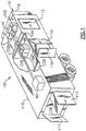
- FIG. 1 there is shown a truck trailer 100 having a refrigerated container 110 subdivided, i.e., compartmentalized, by internal partition walls 104, 106 into a forward cargo compartment 112, a central cargo compartment 114 and an aft cargo compartment 116.
- the cargo compartments 112, 114 and 116 have access doors 113, 115 and 117, respectively, which open directly to the exterior of the truck trailer to facilitate loading of product into the respective cargo compartments 112, 114 and 116.
- the container 100 is equipped with a transport refrigeration system 10 for regulating and maintaining within each of the respective cargo compartments 112, 114 and 116 a desired storage temperature range selected for the product being shipped therein.
- embodiments will be described herein with reference to the three compartment, refrigerated container, illustrated in FIG. 1 , it is to be understood that embodiments may also be used in connection with truck trailers having compartmentalized containers with the cargo compartments arranged otherwise, and also in connection with other refrigerated transport vessels, including for example refrigerated container of a truck, or a refrigerated freight container of compartmentalized design for transporting perishable product by ship, rail and/or road transport.
- Transport refrigeration system 10 includes a main evaporator 40 and remote evaporators 50 and 60.
- Each of the evaporators 40, 50 and 60 may comprise a conventional finned tube coil heat exchanger.
- Each compartment includes a return air temperature sensor 41, 51 and 61 ( FIG. 2 ), to measure the return air temperature from compartments 112, 114 and 116, respectively.
- the transport refrigeration system 10 is mounted as in conventional practice to an exterior wall of the truck trailer 100, for example the front wall 102 thereof, with the compressor 20 and the heat rejecting heat exchanger 117 ( FIG. 2 ) disposed externally of the refrigerated container 110 in a housing 16.
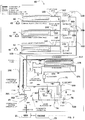
- FIG. 2 is a schematic representation of the multiple evaporator transport refrigeration unit 10 in an exemplary embodiment.
- compressor 20 is a scroll compressor, however other compressors such as reciprocating or screw compressors are possible without limiting the scope of the disclosure.
- Compressor 20 includes a motor 114 which may be an integrated electric drive motor driven by a synchronous generator 21 operating at low speed (for example, 45 Hz) or high speed (for example, 65 Hz).
- Generator 21 may be driven by a diesel engine 23 of a vehicle that tows truck trailer 100.
- generator 21 may be driven by a stand-alone engine 23.
- engine 23 a diesel engine, such as a four cylinder, 2200 cc displacement diesel engine which operates at a high speed (about 1950 RPM) or at low speed (about 1350 RPM).
- a heat rejecting heat exchanger 117 e.g., condenser or gas cooler
- the refrigerant condenses to a high pressure/high temperature liquid and flows to the receiver 120 that provides storage for excess liquid refrigerant during low temperature operation. From the receiver 120, the refrigerant flows to a subcooler 121, which increases the refrigerant subcooling.
- Subcooler 121 may be positioned adjacent heat rejecting heat exchanger 117, and cooled by air flow from the heat rejecting heat exchanger fan.
- a filter-drier 124 keeps the refrigerant clean and dry, and outlets refrigerant to a first refrigerant flow path 71 of an economizer heat exchanger 148, which increases the refrigerant subcooling.
- Economizer heat exchanger 148 may be a plate-type heat exchanger, providing refrigerant to refrigerant heat exchange between a first refrigerant flow path 71 and second refrigerant flow path 72.
- refrigerant flows from the economizer heat exchanger 148 to a plurality of evaporator expansion devices 140, 150 and 160, connected in parallel with the first refrigerant flow path 71.
- Evaporator expansion devices 140, 150 and 160 are associated with evaporators 40, 50 and 60, respectively, to control ingress of refrigerant to the respective evaporators 40, 50 and 60.
- the evaporator expansion devices 140, 150 and 160 may be electronic evaporator expansion devices controlled by a controller 550. Controller 550 is shown as distributed for ease of illustration. It is understood that controller 550 may be a single device that controls the evaporator expansion devices 140, 150 and 160.
- Evaporator expansion device 140 is controlled by controller 550 in response to signals from a first evaporator outlet temperature sensor 141 and first evaporator outlet pressure sensor 142.
- Evaporator expansion device 150 is controlled by controller 550 in response to signals from a second evaporator outlet temperature sensor 151 and second evaporator outlet pressure sensor 152.
- Evaporator expansion device 160 is controlled by controller 550 in response to signals from a third evaporator outlet temperature sensor 161 and third evaporator outlet pressure sensor 162.
- Evaporator fans (not shown) draw or push air over the evaporators 40, 50 and 60 to condition the air in compartments 112, 114, and 116, respectively.
- Refrigerant vapor from evaporators 40, 50 and 60 is coupled to a common compressor inlet path 200 coupled to a compressor suction port through a compressor suction modulation valve 201 and compressor suction service valve 202.
- Refrigeration system 10 further includes a second refrigerant flow path 72 through the economizer heat exchanger 148.
- the second refrigerant flow path 72 is connected between the first refrigerant flow path 71 and an intermediate inlet port 167 of the compressor 20.
- the intermediate inlet port 167 is located at an intermediate location along a compression path between compressor suction port and compressor discharge port.
- An economizer expansion device 77 is positioned in the second refrigerant flow path 72, upstream of the economizer heat exchanger 148.
- the economizer expansion device 77 may be an electronic economizer expansion device controlled by controller 550.
- controller 550 controls economizer expansion device 77 to allow refrigerant to pass through the second refrigerant flow path 72, through economizer heat exchanger 148 and to the intermediate inlet port 167.
- the economizer expansion device 77 serves to expand and cool the refrigerant, which proceeds into the economizer counter-flow heat exchanger 148, thereby sub-cooling the liquid refrigerant in the first refrigerant flow path 71 proceeding to evaporator expansion devices 140, 150 and 160.
- Controller 550 may include a microprocessor and its associated memory.
- the memory of controller can contain operator or owner preselected, desired values for various operating parameters within the system 10 including, but not limited to, temperature set points for various locations within the system 10 or the container, pressure limits, current limits, engine speed limits, and any variety of other desired operating parameters or limits with the system 10.
- controller 550 includes a microprocessor board that contains microprocessor and memory, an input/output (I/O) board, which contains an analog to digital converter which receives temperature inputs and pressure inputs from various points in the system, AC current inputs, DC current inputs, voltage inputs and humidity level inputs.
- I/O board includes drive circuits or field effect transistors (“FETs”) and relays which receive signals or current from the controller 550 and in turn control various external or peripheral devices in the system 10, such as economizer expansion valve 77, for example.
- FETs field effect transistors
- controller 550 controls evaporator expansion devices 140, 150 and 160 based on sensed superheat at the outlet of each of the respective evaporators 40, 50 and 60. Controller 550 determines the sensed superheat for each evaporator 40, 50 and 60 based on the respective evaporator outlet temperature sensor and evaporator outlet pressure sensor. The sensed superheat is then compared to a superheat setpoint for each evaporator 40, 50 and 60 to control the evaporator expansion device associated with each evaporator 40, 50 and 60.
- evaporator 40, 50 and 60 are coupled to common suction plenum 200, when simultaneous cooling is required at two compartments at two differing compartment temperatures, the saturation temperature is the same across evaporators 40, 50 and 60. This causes the superheat in the higher temperature compartment to be high, causing a large discrepancy between the sensed superheat and the superheat setpoint for that compartment.
- Embodiments discussed herein address this superheat error, by adjusting the superheat setpoint of the evaporator in the warmer compartment to be a function of the return air temperature of the warmer compartment and return air temperature of the cooler compartment.
- the return air temperature for each compartment is measured by return air temperature sensors 41, 51, and 61.
- the superheat error e.g., difference between the sensed superheat and the superheat setpoint
- FIG. 3 is a flowchart of a method for controlling the multi-compartment refrigeration system in an exemplary embodiment.
- the process begins at 300 where two compartments of the system demand cooling at different temperatures.
- controller 550 determines a temperature difference between the return air temperature of the warmer compartment, RATwarm, and the return air temperature of the cooler compartment, RATcold.
- the original superheat setpoint, SHorg for the warmer compartment is added to the temperature difference between the return air temperature of the warmer compartment, RATwarm, and the return air temperature of the cooler compartment, RATcold, to define an adjusted superheat setpoint, SHadj, for the warmer compartment.
- expansion device for the warmer compartment is controlled using the adjusted superheat setpoint, SHadj.
- Embodiments discussed herein lead to better system stability and less chance of engine disturbances (stalls).
- the total system efficiency will improve because less saturation flooding of the frozen evaporator will occur from excessive flow of the perishable compartment. Additionally, expansion device life expectancy will improve due to reduced pulsing. Another benefit is reduced transient flooding and slugging to the compressor.
Landscapes
- Engineering & Computer Science (AREA)
- Physics & Mathematics (AREA)
- Mechanical Engineering (AREA)
- Thermal Sciences (AREA)
- General Engineering & Computer Science (AREA)
- Chemical & Material Sciences (AREA)
- Combustion & Propulsion (AREA)
- Devices That Are Associated With Refrigeration Equipment (AREA)
Claims (9)
- Système de réfrigération de transport à compartiments multiples (10) comprenant :un compresseur (20) ayant un orifice d'aspiration et un orifice d'évacuation, l'orifice d'aspiration de compresseur étant couplé à un chemin d'entrée de compresseur ;un échangeur de chaleur à rejet de chaleur (117) en aval de l'orifice d'évacuation de compresseur ;un premier dispositif de détente d'évaporateur (140) en aval de l'échangeur de chaleur à rejet de chaleur (117) ;un premier évaporateur (40) ayant une première entrée d'évaporateur couplée au premier dispositif de détente d'évaporateur (140) et une première sortie d'évaporateur couplée au chemin d'entrée de compresseur (200), le premier évaporateur (40) permettant de refroidir un premier compartiment d'un récipient à une première température ;un premier capteur de température d'air de retour (41) pour générer la première température ;un second dispositif de détente d'évaporateur (150) en aval de l'échangeur de chaleur à rejet de chaleur (117) ;un second évaporateur (50) ayant une seconde entrée d'évaporateur couplée au second dispositif de détente d'évaporateur (150) et une seconde sortie d'évaporateur couplée au chemin d'entrée de compresseur (200), le second évaporateur (50) permettant de refroidir un second compartiment du récipient à une seconde température supérieure à la première température ;un second capteur de température d'air de retour (51) pour générer la seconde température ; etun dispositif de commande (550) pour commander le premier dispositif de détente d'évaporateur (140) en réponse à un premier point de consigne de surchauffe et pour commander le second dispositif de détente d'évaporateur (150) en réponse à un second point de consigne de surchauffe ;caractérisé en ce quele dispositif de commande (550) est configuré pour régler le second point de consigne de surchauffe en réponse à la seconde température et à la première température.
- Système de réfrigération de transport à compartiments multiples (10) selon la revendication 1, dans lequel :
le dispositif de commande (550) règle le second point de consigne de surchauffe en réponse à une différence entre la seconde température et la première température. - Système de réfrigération de transport à compartiments multiples (10) selon la revendication 1, dans lequel :
le dispositif de commande (550) règle le second point de consigne de surchauffe en déterminant un second point de consigne de surchauffe réglé en réponse à un second point de consigne de surchauffe d'origine et à une différence entre la seconde température et la première température. - Système de réfrigération de transport à compartiments multiples (10) selon la revendication 1, dans lequel :
le dispositif de commande (550) règle le second point de consigne de surchauffe en déterminant un second point de consigne de surchauffe réglé égal à un second point de consigne de surchauffe d'origine plus une différence entre la seconde température et la première température. - Système de réfrigération de transport à compartiments multiples (10) selon la revendication 1, dans lequel :
le dispositif de commande (550) commande le second dispositif de détente d'évaporateur (150) en réponse au second point de consigne de surchauffe et à une seconde surchauffe détectée au niveau de la seconde sortie d'évaporateur. - Procédé de fonctionnement d'un système de réfrigération de transport à compartiments multiples (10), le procédé comprenant :le fonctionnement d'un premier évaporateur (40) et d'un premier dispositif de détente d'évaporateur (140) pour refroidir un premier compartiment d'un récipient à une première température, une première sortie d'évaporateur étant couplée à un chemin d'entrée de compresseur (200), la première température étant générée par un premier capteur de température d'air de retour (41) ;le fonctionnement d'un second évaporateur (50) et d'un second dispositif de détente d'évaporateur (150) pour refroidir un second compartiment d'un récipient à une seconde température supérieure à la première température, une seconde sortie d'évaporateur étant couplée au chemin d'entrée de compresseur (200), la seconde la température étant générée par un second capteur de température d'air de retour (51) ;la commande du premier dispositif de détente d'évaporateur (140) en réponse à un premier point de consigne de surchauffe et la commande du second dispositif de détente d'évaporateur (150) en réponse à un second point de consigne de surchauffe, le dispositif de commande réglant le second point de consigne de surchauffe en réponse à la seconde température et à la première température.
- Procédé selon la revendication 6, dans lequel :
le réglage du second point de consigne de surchauffe comporte la détermination d'un second point de consigne de surchauffe réglé en réponse à un second point de consigne de surchauffe d'origine et à une différence entre la seconde température et la première température. - Procédé selon la revendication 6, dans lequel :
le réglage du second point de consigne de surchauffe comporte la détermination d'un second point de consigne de surchauffe réglé égal à un second point de consigne de surchauffe d'origine plus une différence entre la seconde température et la première température. - Procédé selon la revendication 6, dans lequel :
la commande du second dispositif de détente d'évaporateur (150) comporte la détermination d'une erreur entre le second point de consigne de surchauffe et une seconde surchauffe détectée au niveau de la seconde sortie d'évaporateur.
Applications Claiming Priority (2)
| Application Number | Priority Date | Filing Date | Title |
|---|---|---|---|
| US201461924941P | 2014-01-08 | 2014-01-08 | |
| PCT/US2015/010437 WO2015105845A1 (fr) | 2014-01-08 | 2015-01-07 | Commande adaptative de système de réfrigération de transport à compartiments multiples |
Publications (2)
| Publication Number | Publication Date |
|---|---|
| EP3092448A1 EP3092448A1 (fr) | 2016-11-16 |
| EP3092448B1 true EP3092448B1 (fr) | 2020-09-16 |
Family
ID=52396836
Family Applications (1)
| Application Number | Title | Priority Date | Filing Date |
|---|---|---|---|
| EP15701275.8A Active EP3092448B1 (fr) | 2014-01-08 | 2015-01-07 | Commande adaptative de système de réfrigération de transport à compartiments multiples |
Country Status (3)
| Country | Link |
|---|---|
| US (1) | US10337767B2 (fr) |
| EP (1) | EP3092448B1 (fr) |
| WO (1) | WO2015105845A1 (fr) |
Families Citing this family (12)
| Publication number | Priority date | Publication date | Assignee | Title |
|---|---|---|---|---|
| EP3440418B1 (fr) | 2016-04-05 | 2026-01-07 | Carrier Corporation | Système de tracteur et de remorque |
| US10959395B2 (en) * | 2017-06-23 | 2021-03-30 | Smithway, Inc. | Poultry curtain trailer system |
| WO2019013985A1 (fr) | 2017-07-11 | 2019-01-17 | Walmart Apollo, Llc | Système de compartiment de camion réglable |
| US11098943B2 (en) | 2018-04-13 | 2021-08-24 | Carrier Corporation | Transportation refrigeration system with unequal sized heat exchangers |
| CN109405393A (zh) * | 2018-11-15 | 2019-03-01 | 浙江金字机械电器有限公司 | 列车移动式冷藏箱 |
| US11312308B2 (en) * | 2019-11-08 | 2022-04-26 | GM Global Technologies Operations LLC | Universal storage system for a motor vehicle |
| CN113028667B (zh) | 2019-12-25 | 2024-12-06 | 开利公司 | 运输制冷系统以及用于运输制冷系统的can id分配方法 |
| IT202100009611A1 (it) | 2021-04-16 | 2022-10-16 | Mitsubishi Electric Hydronics & It Cooling Systems S P A | Metodo di controllo di un apparecchio per ciclo di refrigerazione raffreddato ad aria |
| EP4083537A1 (fr) * | 2021-04-26 | 2022-11-02 | Electrolux Appliances Aktiebolag | Un système de refroidissement avec plusieurs lignes de refroidissement avec un contrôleur configuré |
| US20220349626A1 (en) * | 2021-04-30 | 2022-11-03 | Zhao Ri Gan | Air-cooled progressively two-stage refrigeration system |
| EP4303503A1 (fr) * | 2022-07-05 | 2024-01-10 | Carrier Corporation | Système de réfrigération de transport à compartiments multiples |
| EP4425731A1 (fr) * | 2023-03-03 | 2024-09-04 | Thermo King LLC | Système de stabilisation d'une liaison cc |
Family Cites Families (19)
| Publication number | Priority date | Publication date | Assignee | Title |
|---|---|---|---|---|
| US5899084A (en) | 1997-01-10 | 1999-05-04 | Chiquita Brands, Inc. | Method and apparatus for ripening perishable products in a temperature-controlled room |
| US6148628A (en) | 1999-03-26 | 2000-11-21 | Carrier Corporation | Electronic expansion valve without pressure sensor reading |
| US6973794B2 (en) | 2000-03-14 | 2005-12-13 | Hussmann Corporation | Refrigeration system and method of operating the same |
| DE102004024664A1 (de) | 2004-05-18 | 2005-12-08 | Emerson Electric Gmbh & Co. Ohg | Steuereinrichtung für eine Kälte- oder Klimaanlage |
| DK1974171T3 (da) | 2006-09-29 | 2014-08-18 | Carrier Corp | Kompressionssystem til kølemiddeldamp med flash tank modtager |
| US8397528B2 (en) | 2007-01-08 | 2013-03-19 | Carrier Corporation | Refrigerated transport system |
| BRPI0721189A2 (pt) | 2007-02-02 | 2013-01-01 | Carrier Corp | método para operar uma unidade de refrigeração de transporte |
| US20100132399A1 (en) | 2007-04-24 | 2010-06-03 | Carrier Corporation | Transcritical refrigerant vapor compression system with charge management |
| EP2147264B1 (fr) | 2007-04-24 | 2019-01-16 | Carrier Corporation | Système de compression de vapeur de réfrigérant |
| CN101688697B (zh) | 2007-04-24 | 2012-10-03 | 开利公司 | 具有双节能器回路的制冷剂蒸汽压缩系统 |
| WO2008143611A1 (fr) | 2007-05-17 | 2008-11-27 | Carrier Corporation | Système de réfrigération à cycle d'économie avec commande de flux |
| JP5210626B2 (ja) * | 2007-12-27 | 2013-06-12 | 三菱重工業株式会社 | 陸上輸送用冷凍装置及び陸上輸送用冷凍装置の運転制御方法 |
| JP5045524B2 (ja) * | 2008-03-31 | 2012-10-10 | ダイキン工業株式会社 | 冷凍装置 |
| EP2313713A2 (fr) | 2008-07-04 | 2011-04-27 | Carrier Corporation | Essai de système de transport réfrigéré |
| DK2340406T3 (en) | 2008-10-01 | 2018-12-17 | Carrier Corp | Liquid Vapor Separation in Transcritical Refrigerant Cycle |
| WO2010051198A2 (fr) * | 2008-10-31 | 2010-05-06 | Carrier Corporation | Commande de systèmes de compression de vapeur de réfrigérant à zones multiples |
| WO2011112495A2 (fr) | 2010-03-08 | 2011-09-15 | Carrier Corporation | Appareils et procédés de distribution de fluide frigorigène pour un système de transport réfrigéré |
| CN102803865A (zh) | 2010-03-08 | 2012-11-28 | 开利公司 | 运输制冷系统中的能力和压力控制 |
| US20140326010A1 (en) * | 2011-12-19 | 2014-11-06 | Toyota Jidosha Kabushiki Kaisha | Cooling device |
-
2015
- 2015-01-07 US US15/110,181 patent/US10337767B2/en active Active
- 2015-01-07 WO PCT/US2015/010437 patent/WO2015105845A1/fr not_active Ceased
- 2015-01-07 EP EP15701275.8A patent/EP3092448B1/fr active Active
Non-Patent Citations (1)
| Title |
|---|
| None * |
Also Published As
| Publication number | Publication date |
|---|---|
| WO2015105845A1 (fr) | 2015-07-16 |
| US10337767B2 (en) | 2019-07-02 |
| US20160334142A1 (en) | 2016-11-17 |
| EP3092448A1 (fr) | 2016-11-16 |
Similar Documents
| Publication | Publication Date | Title |
|---|---|---|
| EP3092448B1 (fr) | Commande adaptative de système de réfrigération de transport à compartiments multiples | |
| EP3014197B1 (fr) | Système de réfrigération de transport à compartiments multiples ayant une vanne d'isolement d'évaporateur | |
| EP2951512B1 (fr) | Système frigorifique de transport à compartiments multiples ayant un économiseur | |
| CN101600917B (zh) | 操作具有远程蒸发器的运输制冷单元的方法 | |
| EP3168553B1 (fr) | Procédés et systèmes de fonctionnement de zone coordonnée dans un système de réfrigération de transport multizone | |
| US20240010049A1 (en) | Multi-compartment transport refrigeration system | |
| EP3320277B1 (fr) | Système frigorifique de transport multi-compartiments à économiseur | |
| US11098943B2 (en) | Transportation refrigeration system with unequal sized heat exchangers | |
| US20210268877A1 (en) | Multi-temperature transport refrigeration system and method | |
| EP4234290B1 (fr) | Système de réfrigération de transport alimenté par une pile à combustible | |
| US11619431B2 (en) | Method of defrosting a multiple heat absorption heat exchanger refrigeration system | |
| WO2019199388A1 (fr) | Système de réfrigération permettant le transport | |
| HK1137800B (en) | Method for operating transport refrigeration unit with remote evaporator |
Legal Events
| Date | Code | Title | Description |
|---|---|---|---|
| PUAI | Public reference made under article 153(3) epc to a published international application that has entered the european phase |
Free format text: ORIGINAL CODE: 0009012 |
|
| 17P | Request for examination filed |
Effective date: 20160801 |
|
| AK | Designated contracting states |
Kind code of ref document: A1 Designated state(s): AL AT BE BG CH CY CZ DE DK EE ES FI FR GB GR HR HU IE IS IT LI LT LU LV MC MK MT NL NO PL PT RO RS SE SI SK SM TR |
|
| AX | Request for extension of the european patent |
Extension state: BA ME |
|
| DAX | Request for extension of the european patent (deleted) | ||
| GRAP | Despatch of communication of intention to grant a patent |
Free format text: ORIGINAL CODE: EPIDOSNIGR1 |
|
| STAA | Information on the status of an ep patent application or granted ep patent |
Free format text: STATUS: GRANT OF PATENT IS INTENDED |
|
| INTG | Intention to grant announced |
Effective date: 20200422 |
|
| GRAS | Grant fee paid |
Free format text: ORIGINAL CODE: EPIDOSNIGR3 |
|
| GRAA | (expected) grant |
Free format text: ORIGINAL CODE: 0009210 |
|
| STAA | Information on the status of an ep patent application or granted ep patent |
Free format text: STATUS: THE PATENT HAS BEEN GRANTED |
|
| AK | Designated contracting states |
Kind code of ref document: B1 Designated state(s): AL AT BE BG CH CY CZ DE DK EE ES FI FR GB GR HR HU IE IS IT LI LT LU LV MC MK MT NL NO PL PT RO RS SE SI SK SM TR |
|
| REG | Reference to a national code |
Ref country code: GB Ref legal event code: FG4D |
|
| REG | Reference to a national code |
Ref country code: CH Ref legal event code: EP |
|
| REG | Reference to a national code |
Ref country code: DE Ref legal event code: R096 Ref document number: 602015059121 Country of ref document: DE |
|
| REG | Reference to a national code |
Ref country code: IE Ref legal event code: FG4D |
|
| REG | Reference to a national code |
Ref country code: AT Ref legal event code: REF Ref document number: 1314520 Country of ref document: AT Kind code of ref document: T Effective date: 20201015 |
|
| PG25 | Lapsed in a contracting state [announced via postgrant information from national office to epo] |
Ref country code: HR Free format text: LAPSE BECAUSE OF FAILURE TO SUBMIT A TRANSLATION OF THE DESCRIPTION OR TO PAY THE FEE WITHIN THE PRESCRIBED TIME-LIMIT Effective date: 20200916 Ref country code: GR Free format text: LAPSE BECAUSE OF FAILURE TO SUBMIT A TRANSLATION OF THE DESCRIPTION OR TO PAY THE FEE WITHIN THE PRESCRIBED TIME-LIMIT Effective date: 20201217 Ref country code: NO Free format text: LAPSE BECAUSE OF FAILURE TO SUBMIT A TRANSLATION OF THE DESCRIPTION OR TO PAY THE FEE WITHIN THE PRESCRIBED TIME-LIMIT Effective date: 20201216 Ref country code: SE Free format text: LAPSE BECAUSE OF FAILURE TO SUBMIT A TRANSLATION OF THE DESCRIPTION OR TO PAY THE FEE WITHIN THE PRESCRIBED TIME-LIMIT Effective date: 20200916 Ref country code: BG Free format text: LAPSE BECAUSE OF FAILURE TO SUBMIT A TRANSLATION OF THE DESCRIPTION OR TO PAY THE FEE WITHIN THE PRESCRIBED TIME-LIMIT Effective date: 20201216 Ref country code: FI Free format text: LAPSE BECAUSE OF FAILURE TO SUBMIT A TRANSLATION OF THE DESCRIPTION OR TO PAY THE FEE WITHIN THE PRESCRIBED TIME-LIMIT Effective date: 20200916 |
|
| REG | Reference to a national code |
Ref country code: AT Ref legal event code: MK05 Ref document number: 1314520 Country of ref document: AT Kind code of ref document: T Effective date: 20200916 |
|
| PG25 | Lapsed in a contracting state [announced via postgrant information from national office to epo] |
Ref country code: RS Free format text: LAPSE BECAUSE OF FAILURE TO SUBMIT A TRANSLATION OF THE DESCRIPTION OR TO PAY THE FEE WITHIN THE PRESCRIBED TIME-LIMIT Effective date: 20200916 Ref country code: LV Free format text: LAPSE BECAUSE OF FAILURE TO SUBMIT A TRANSLATION OF THE DESCRIPTION OR TO PAY THE FEE WITHIN THE PRESCRIBED TIME-LIMIT Effective date: 20200916 |
|
| REG | Reference to a national code |
Ref country code: LT Ref legal event code: MG4D |
|
| PG25 | Lapsed in a contracting state [announced via postgrant information from national office to epo] |
Ref country code: CZ Free format text: LAPSE BECAUSE OF FAILURE TO SUBMIT A TRANSLATION OF THE DESCRIPTION OR TO PAY THE FEE WITHIN THE PRESCRIBED TIME-LIMIT Effective date: 20200916 Ref country code: RO Free format text: LAPSE BECAUSE OF FAILURE TO SUBMIT A TRANSLATION OF THE DESCRIPTION OR TO PAY THE FEE WITHIN THE PRESCRIBED TIME-LIMIT Effective date: 20200916 Ref country code: SM Free format text: LAPSE BECAUSE OF FAILURE TO SUBMIT A TRANSLATION OF THE DESCRIPTION OR TO PAY THE FEE WITHIN THE PRESCRIBED TIME-LIMIT Effective date: 20200916 Ref country code: EE Free format text: LAPSE BECAUSE OF FAILURE TO SUBMIT A TRANSLATION OF THE DESCRIPTION OR TO PAY THE FEE WITHIN THE PRESCRIBED TIME-LIMIT Effective date: 20200916 Ref country code: PT Free format text: LAPSE BECAUSE OF FAILURE TO SUBMIT A TRANSLATION OF THE DESCRIPTION OR TO PAY THE FEE WITHIN THE PRESCRIBED TIME-LIMIT Effective date: 20210118 Ref country code: LT Free format text: LAPSE BECAUSE OF FAILURE TO SUBMIT A TRANSLATION OF THE DESCRIPTION OR TO PAY THE FEE WITHIN THE PRESCRIBED TIME-LIMIT Effective date: 20200916 |
|
| PG25 | Lapsed in a contracting state [announced via postgrant information from national office to epo] |
Ref country code: PL Free format text: LAPSE BECAUSE OF FAILURE TO SUBMIT A TRANSLATION OF THE DESCRIPTION OR TO PAY THE FEE WITHIN THE PRESCRIBED TIME-LIMIT Effective date: 20200916 Ref country code: IS Free format text: LAPSE BECAUSE OF FAILURE TO SUBMIT A TRANSLATION OF THE DESCRIPTION OR TO PAY THE FEE WITHIN THE PRESCRIBED TIME-LIMIT Effective date: 20210116 Ref country code: AL Free format text: LAPSE BECAUSE OF FAILURE TO SUBMIT A TRANSLATION OF THE DESCRIPTION OR TO PAY THE FEE WITHIN THE PRESCRIBED TIME-LIMIT Effective date: 20200916 Ref country code: AT Free format text: LAPSE BECAUSE OF FAILURE TO SUBMIT A TRANSLATION OF THE DESCRIPTION OR TO PAY THE FEE WITHIN THE PRESCRIBED TIME-LIMIT Effective date: 20200916 Ref country code: ES Free format text: LAPSE BECAUSE OF FAILURE TO SUBMIT A TRANSLATION OF THE DESCRIPTION OR TO PAY THE FEE WITHIN THE PRESCRIBED TIME-LIMIT Effective date: 20200916 |
|
| REG | Reference to a national code |
Ref country code: DE Ref legal event code: R097 Ref document number: 602015059121 Country of ref document: DE |
|
| PG25 | Lapsed in a contracting state [announced via postgrant information from national office to epo] |
Ref country code: SK Free format text: LAPSE BECAUSE OF FAILURE TO SUBMIT A TRANSLATION OF THE DESCRIPTION OR TO PAY THE FEE WITHIN THE PRESCRIBED TIME-LIMIT Effective date: 20200916 |
|
| PLBE | No opposition filed within time limit |
Free format text: ORIGINAL CODE: 0009261 |
|
| STAA | Information on the status of an ep patent application or granted ep patent |
Free format text: STATUS: NO OPPOSITION FILED WITHIN TIME LIMIT |
|
| 26N | No opposition filed |
Effective date: 20210617 |
|
| PG25 | Lapsed in a contracting state [announced via postgrant information from national office to epo] |
Ref country code: SI Free format text: LAPSE BECAUSE OF FAILURE TO SUBMIT A TRANSLATION OF THE DESCRIPTION OR TO PAY THE FEE WITHIN THE PRESCRIBED TIME-LIMIT Effective date: 20200916 Ref country code: DK Free format text: LAPSE BECAUSE OF FAILURE TO SUBMIT A TRANSLATION OF THE DESCRIPTION OR TO PAY THE FEE WITHIN THE PRESCRIBED TIME-LIMIT Effective date: 20200916 Ref country code: MC Free format text: LAPSE BECAUSE OF FAILURE TO SUBMIT A TRANSLATION OF THE DESCRIPTION OR TO PAY THE FEE WITHIN THE PRESCRIBED TIME-LIMIT Effective date: 20200916 |
|
| REG | Reference to a national code |
Ref country code: CH Ref legal event code: PL |
|
| PG25 | Lapsed in a contracting state [announced via postgrant information from national office to epo] |
Ref country code: LU Free format text: LAPSE BECAUSE OF NON-PAYMENT OF DUE FEES Effective date: 20210107 |
|
| REG | Reference to a national code |
Ref country code: BE Ref legal event code: MM Effective date: 20210131 Ref country code: NL Ref legal event code: FP |
|
| PG25 | Lapsed in a contracting state [announced via postgrant information from national office to epo] |
Ref country code: IT Free format text: LAPSE BECAUSE OF FAILURE TO SUBMIT A TRANSLATION OF THE DESCRIPTION OR TO PAY THE FEE WITHIN THE PRESCRIBED TIME-LIMIT Effective date: 20200916 |
|
| PG25 | Lapsed in a contracting state [announced via postgrant information from national office to epo] |
Ref country code: CH Free format text: LAPSE BECAUSE OF NON-PAYMENT OF DUE FEES Effective date: 20210131 Ref country code: LI Free format text: LAPSE BECAUSE OF NON-PAYMENT OF DUE FEES Effective date: 20210131 |
|
| PG25 | Lapsed in a contracting state [announced via postgrant information from national office to epo] |
Ref country code: IE Free format text: LAPSE BECAUSE OF NON-PAYMENT OF DUE FEES Effective date: 20210107 |
|
| PG25 | Lapsed in a contracting state [announced via postgrant information from national office to epo] |
Ref country code: BE Free format text: LAPSE BECAUSE OF NON-PAYMENT OF DUE FEES Effective date: 20210131 |
|
| PG25 | Lapsed in a contracting state [announced via postgrant information from national office to epo] |
Ref country code: HU Free format text: LAPSE BECAUSE OF FAILURE TO SUBMIT A TRANSLATION OF THE DESCRIPTION OR TO PAY THE FEE WITHIN THE PRESCRIBED TIME-LIMIT; INVALID AB INITIO Effective date: 20150107 |
|
| PG25 | Lapsed in a contracting state [announced via postgrant information from national office to epo] |
Ref country code: CY Free format text: LAPSE BECAUSE OF FAILURE TO SUBMIT A TRANSLATION OF THE DESCRIPTION OR TO PAY THE FEE WITHIN THE PRESCRIBED TIME-LIMIT Effective date: 20200916 |
|
| PG25 | Lapsed in a contracting state [announced via postgrant information from national office to epo] |
Ref country code: MK Free format text: LAPSE BECAUSE OF FAILURE TO SUBMIT A TRANSLATION OF THE DESCRIPTION OR TO PAY THE FEE WITHIN THE PRESCRIBED TIME-LIMIT Effective date: 20200916 |
|
| PG25 | Lapsed in a contracting state [announced via postgrant information from national office to epo] |
Ref country code: TR Free format text: LAPSE BECAUSE OF FAILURE TO SUBMIT A TRANSLATION OF THE DESCRIPTION OR TO PAY THE FEE WITHIN THE PRESCRIBED TIME-LIMIT Effective date: 20200916 |
|
| PG25 | Lapsed in a contracting state [announced via postgrant information from national office to epo] |
Ref country code: MT Free format text: LAPSE BECAUSE OF FAILURE TO SUBMIT A TRANSLATION OF THE DESCRIPTION OR TO PAY THE FEE WITHIN THE PRESCRIBED TIME-LIMIT Effective date: 20200916 |
|
| PGFP | Annual fee paid to national office [announced via postgrant information from national office to epo] |
Ref country code: NL Payment date: 20241219 Year of fee payment: 11 |
|
| PGFP | Annual fee paid to national office [announced via postgrant information from national office to epo] |
Ref country code: GB Payment date: 20241219 Year of fee payment: 11 |
|
| PGFP | Annual fee paid to national office [announced via postgrant information from national office to epo] |
Ref country code: FR Payment date: 20241220 Year of fee payment: 11 |
|
| PGFP | Annual fee paid to national office [announced via postgrant information from national office to epo] |
Ref country code: DE Payment date: 20241218 Year of fee payment: 11 |