EP3092455B1 - Plenumstrennwand mit stufenweiser reaktion für einen ofen - Google Patents
Plenumstrennwand mit stufenweiser reaktion für einen ofen Download PDFInfo
- Publication number
- EP3092455B1 EP3092455B1 EP15735568.6A EP15735568A EP3092455B1 EP 3092455 B1 EP3092455 B1 EP 3092455B1 EP 15735568 A EP15735568 A EP 15735568A EP 3092455 B1 EP3092455 B1 EP 3092455B1
- Authority
- EP
- European Patent Office
- Prior art keywords
- refractory brick
- hexagonally
- shaped portions
- brick member
- members
- Prior art date
- Legal status (The legal status is an assumption and is not a legal conclusion. Google has not performed a legal analysis and makes no representation as to the accuracy of the status listed.)
- Active
Links
- 238000006243 chemical reaction Methods 0.000 title claims description 25
- 238000005192 partition Methods 0.000 title description 28
- 239000011449 brick Substances 0.000 claims description 134
- 238000000034 method Methods 0.000 claims description 30
- 238000002347 injection Methods 0.000 claims description 21
- 239000007924 injection Substances 0.000 claims description 21
- 230000007704 transition Effects 0.000 claims description 13
- 238000009826 distribution Methods 0.000 claims description 12
- 230000013011 mating Effects 0.000 claims description 12
- 238000004891 communication Methods 0.000 claims description 11
- 239000012530 fluid Substances 0.000 claims description 8
- 239000007789 gas Substances 0.000 description 30
- QGZKDVFQNNGYKY-UHFFFAOYSA-N Ammonia Chemical compound N QGZKDVFQNNGYKY-UHFFFAOYSA-N 0.000 description 8
- 238000002485 combustion reaction Methods 0.000 description 6
- RWSOTUBLDIXVET-UHFFFAOYSA-N Dihydrogen sulfide Chemical compound S RWSOTUBLDIXVET-UHFFFAOYSA-N 0.000 description 5
- NINIDFKCEFEMDL-UHFFFAOYSA-N Sulfur Chemical compound [S] NINIDFKCEFEMDL-UHFFFAOYSA-N 0.000 description 5
- 229910000037 hydrogen sulfide Inorganic materials 0.000 description 5
- QAOWNCQODCNURD-UHFFFAOYSA-N Sulfuric acid Chemical compound OS(O)(=O)=O QAOWNCQODCNURD-UHFFFAOYSA-N 0.000 description 4
- 229910021529 ammonia Inorganic materials 0.000 description 4
- 238000009434 installation Methods 0.000 description 4
- 238000011084 recovery Methods 0.000 description 4
- 239000002253 acid Substances 0.000 description 3
- 238000013461 design Methods 0.000 description 3
- 238000004519 manufacturing process Methods 0.000 description 3
- 229910052717 sulfur Inorganic materials 0.000 description 3
- 239000011593 sulfur Substances 0.000 description 3
- 230000000903 blocking effect Effects 0.000 description 2
- 238000005266 casting Methods 0.000 description 2
- 238000000354 decomposition reaction Methods 0.000 description 2
- 230000014759 maintenance of location Effects 0.000 description 2
- 238000002156 mixing Methods 0.000 description 2
- 239000011214 refractory ceramic Substances 0.000 description 2
- 239000011819 refractory material Substances 0.000 description 2
- 230000008929 regeneration Effects 0.000 description 2
- 238000011069 regeneration method Methods 0.000 description 2
- PNEYBMLMFCGWSK-UHFFFAOYSA-N aluminium oxide Inorganic materials [O-2].[O-2].[O-2].[Al+3].[Al+3] PNEYBMLMFCGWSK-UHFFFAOYSA-N 0.000 description 1
- 230000015572 biosynthetic process Effects 0.000 description 1
- 238000005467 ceramic manufacturing process Methods 0.000 description 1
- 229910010293 ceramic material Inorganic materials 0.000 description 1
- 230000006378 damage Effects 0.000 description 1
- KZHJGOXRZJKJNY-UHFFFAOYSA-N dioxosilane;oxo(oxoalumanyloxy)alumane Chemical compound O=[Si]=O.O=[Si]=O.O=[Al]O[Al]=O.O=[Al]O[Al]=O.O=[Al]O[Al]=O KZHJGOXRZJKJNY-UHFFFAOYSA-N 0.000 description 1
- 238000005553 drilling Methods 0.000 description 1
- 238000001125 extrusion Methods 0.000 description 1
- 239000000835 fiber Substances 0.000 description 1
- 238000001746 injection moulding Methods 0.000 description 1
- 238000003754 machining Methods 0.000 description 1
- 238000010297 mechanical methods and process Methods 0.000 description 1
- 230000005226 mechanical processes and functions Effects 0.000 description 1
- 238000012986 modification Methods 0.000 description 1
- 230000004048 modification Effects 0.000 description 1
- 229910052863 mullite Inorganic materials 0.000 description 1
- 238000012545 processing Methods 0.000 description 1
- 238000007789 sealing Methods 0.000 description 1
- 238000007569 slipcasting Methods 0.000 description 1
- 239000000126 substance Substances 0.000 description 1
- 238000011144 upstream manufacturing Methods 0.000 description 1
- 239000002918 waste heat Substances 0.000 description 1
- XLYOFNOQVPJJNP-UHFFFAOYSA-N water Substances O XLYOFNOQVPJJNP-UHFFFAOYSA-N 0.000 description 1
Images




Classifications
-
- F—MECHANICAL ENGINEERING; LIGHTING; HEATING; WEAPONS; BLASTING
- F27—FURNACES; KILNS; OVENS; RETORTS
- F27D—DETAILS OR ACCESSORIES OF FURNACES, KILNS, OVENS OR RETORTS, IN SO FAR AS THEY ARE OF KINDS OCCURRING IN MORE THAN ONE KIND OF FURNACE
- F27D1/00—Casings; Linings; Walls; Roofs
- F27D1/0003—Linings or walls
- F27D1/0006—Linings or walls formed from bricks or layers with a particular composition or specific characteristics
-
- B—PERFORMING OPERATIONS; TRANSPORTING
- B01—PHYSICAL OR CHEMICAL PROCESSES OR APPARATUS IN GENERAL
- B01D—SEPARATION
- B01D53/00—Separation of gases or vapours; Recovering vapours of volatile solvents from gases; Chemical or biological purification of waste gases, e.g. engine exhaust gases, smoke, fumes, flue gases, aerosols
- B01D53/34—Chemical or biological purification of waste gases
- B01D53/346—Controlling the process
-
- B—PERFORMING OPERATIONS; TRANSPORTING
- B01—PHYSICAL OR CHEMICAL PROCESSES OR APPARATUS IN GENERAL
- B01D—SEPARATION
- B01D53/00—Separation of gases or vapours; Recovering vapours of volatile solvents from gases; Chemical or biological purification of waste gases, e.g. engine exhaust gases, smoke, fumes, flue gases, aerosols
- B01D53/34—Chemical or biological purification of waste gases
- B01D53/46—Removing components of defined structure
- B01D53/48—Sulfur compounds
- B01D53/52—Hydrogen sulfide
-
- B—PERFORMING OPERATIONS; TRANSPORTING
- B01—PHYSICAL OR CHEMICAL PROCESSES OR APPARATUS IN GENERAL
- B01D—SEPARATION
- B01D53/00—Separation of gases or vapours; Recovering vapours of volatile solvents from gases; Chemical or biological purification of waste gases, e.g. engine exhaust gases, smoke, fumes, flue gases, aerosols
- B01D53/34—Chemical or biological purification of waste gases
- B01D53/46—Removing components of defined structure
- B01D53/54—Nitrogen compounds
- B01D53/58—Ammonia
-
- B—PERFORMING OPERATIONS; TRANSPORTING
- B01—PHYSICAL OR CHEMICAL PROCESSES OR APPARATUS IN GENERAL
- B01D—SEPARATION
- B01D53/00—Separation of gases or vapours; Recovering vapours of volatile solvents from gases; Chemical or biological purification of waste gases, e.g. engine exhaust gases, smoke, fumes, flue gases, aerosols
- B01D53/34—Chemical or biological purification of waste gases
- B01D53/74—General processes for purification of waste gases; Apparatus or devices specially adapted therefor
- B01D53/76—Gas phase processes, e.g. by using aerosols
-
- C—CHEMISTRY; METALLURGY
- C01—INORGANIC CHEMISTRY
- C01B—NON-METALLIC ELEMENTS; COMPOUNDS THEREOF; METALLOIDS OR COMPOUNDS THEREOF NOT COVERED BY SUBCLASS C01C
- C01B17/00—Sulfur; Compounds thereof
- C01B17/69—Sulfur trioxide; Sulfuric acid
- C01B17/74—Preparation
-
- F—MECHANICAL ENGINEERING; LIGHTING; HEATING; WEAPONS; BLASTING
- F23—COMBUSTION APPARATUS; COMBUSTION PROCESSES
- F23G—CREMATION FURNACES; CONSUMING WASTE PRODUCTS BY COMBUSTION
- F23G7/00—Incinerators or other apparatus for consuming industrial waste, e.g. chemicals
- F23G7/06—Incinerators or other apparatus for consuming industrial waste, e.g. chemicals of waste gases or noxious gases, e.g. exhaust gases
- F23G7/061—Incinerators or other apparatus for consuming industrial waste, e.g. chemicals of waste gases or noxious gases, e.g. exhaust gases with supplementary heating
- F23G7/065—Incinerators or other apparatus for consuming industrial waste, e.g. chemicals of waste gases or noxious gases, e.g. exhaust gases with supplementary heating using gaseous or liquid fuel
- F23G7/066—Incinerators or other apparatus for consuming industrial waste, e.g. chemicals of waste gases or noxious gases, e.g. exhaust gases with supplementary heating using gaseous or liquid fuel preheating the waste gas by the heat of the combustion, e.g. recuperation type incinerator
- F23G7/068—Incinerators or other apparatus for consuming industrial waste, e.g. chemicals of waste gases or noxious gases, e.g. exhaust gases with supplementary heating using gaseous or liquid fuel preheating the waste gas by the heat of the combustion, e.g. recuperation type incinerator using regenerative heat recovery means
-
- F—MECHANICAL ENGINEERING; LIGHTING; HEATING; WEAPONS; BLASTING
- F23—COMBUSTION APPARATUS; COMBUSTION PROCESSES
- F23M—CASINGS, LININGS, WALLS OR DOORS SPECIALLY ADAPTED FOR COMBUSTION CHAMBERS, e.g. FIREBRIDGES; DEVICES FOR DEFLECTING AIR, FLAMES OR COMBUSTION PRODUCTS IN COMBUSTION CHAMBERS; SAFETY ARRANGEMENTS SPECIALLY ADAPTED FOR COMBUSTION APPARATUS; DETAILS OF COMBUSTION CHAMBERS, NOT OTHERWISE PROVIDED FOR
- F23M9/00—Baffles or deflectors for air or combustion products; Flame shields
- F23M9/04—Baffles or deflectors for air or combustion products; Flame shields with air supply passages in the baffle or shield
-
- F—MECHANICAL ENGINEERING; LIGHTING; HEATING; WEAPONS; BLASTING
- F23—COMBUSTION APPARATUS; COMBUSTION PROCESSES
- F23M—CASINGS, LININGS, WALLS OR DOORS SPECIALLY ADAPTED FOR COMBUSTION CHAMBERS, e.g. FIREBRIDGES; DEVICES FOR DEFLECTING AIR, FLAMES OR COMBUSTION PRODUCTS IN COMBUSTION CHAMBERS; SAFETY ARRANGEMENTS SPECIALLY ADAPTED FOR COMBUSTION APPARATUS; DETAILS OF COMBUSTION CHAMBERS, NOT OTHERWISE PROVIDED FOR
- F23M9/00—Baffles or deflectors for air or combustion products; Flame shields
- F23M9/06—Baffles or deflectors for air or combustion products; Flame shields in fire-boxes
-
- F—MECHANICAL ENGINEERING; LIGHTING; HEATING; WEAPONS; BLASTING
- F27—FURNACES; KILNS; OVENS; RETORTS
- F27D—DETAILS OR ACCESSORIES OF FURNACES, KILNS, OVENS OR RETORTS, IN SO FAR AS THEY ARE OF KINDS OCCURRING IN MORE THAN ONE KIND OF FURNACE
- F27D1/00—Casings; Linings; Walls; Roofs
- F27D1/04—Casings; Linings; Walls; Roofs characterised by the form, e.g. shape of the bricks or blocks used
-
- F—MECHANICAL ENGINEERING; LIGHTING; HEATING; WEAPONS; BLASTING
- F28—HEAT EXCHANGE IN GENERAL
- F28C—HEAT-EXCHANGE APPARATUS, NOT PROVIDED FOR IN ANOTHER SUBCLASS, IN WHICH THE HEAT-EXCHANGE MEDIA COME INTO DIRECT CONTACT WITHOUT CHEMICAL INTERACTION
- F28C3/00—Other direct-contact heat-exchange apparatus
- F28C3/02—Other direct-contact heat-exchange apparatus the heat-exchange media both being gases or vapours
-
- F—MECHANICAL ENGINEERING; LIGHTING; HEATING; WEAPONS; BLASTING
- F28—HEAT EXCHANGE IN GENERAL
- F28F—DETAILS OF HEAT-EXCHANGE AND HEAT-TRANSFER APPARATUS, OF GENERAL APPLICATION
- F28F21/00—Constructions of heat-exchange apparatus characterised by the selection of particular materials
- F28F21/04—Constructions of heat-exchange apparatus characterised by the selection of particular materials of ceramic; of concrete; of natural stone
-
- B—PERFORMING OPERATIONS; TRANSPORTING
- B01—PHYSICAL OR CHEMICAL PROCESSES OR APPARATUS IN GENERAL
- B01D—SEPARATION
- B01D2251/00—Reactants
- B01D2251/10—Oxidants
- B01D2251/11—Air
-
- B—PERFORMING OPERATIONS; TRANSPORTING
- B01—PHYSICAL OR CHEMICAL PROCESSES OR APPARATUS IN GENERAL
- B01D—SEPARATION
- B01D2258/00—Sources of waste gases
- B01D2258/02—Other waste gases
- B01D2258/0283—Flue gases
-
- F—MECHANICAL ENGINEERING; LIGHTING; HEATING; WEAPONS; BLASTING
- F28—HEAT EXCHANGE IN GENERAL
- F28D—HEAT-EXCHANGE APPARATUS, NOT PROVIDED FOR IN ANOTHER SUBCLASS, IN WHICH THE HEAT-EXCHANGE MEDIA DO NOT COME INTO DIRECT CONTACT
- F28D21/00—Heat-exchange apparatus not covered by any of the groups F28D1/00 - F28D20/00
- F28D2021/0019—Other heat exchangers for particular applications; Heat exchange systems not otherwise provided for
- F28D2021/0056—Other heat exchangers for particular applications; Heat exchange systems not otherwise provided for for ovens or furnaces
Definitions
- reaction furnaces are typically refractory-lined cylinders with inside diameters ranging in size from 91,44 cm (3 feet) to diameters in excess of 609,6 cm (20 feet), with furnace lengths ranging from 609,6 cm (20 feet) to over 3048 cm (100 feet) long.
- the furnaces are configured with a large process burner at one end that discharges into a waste heat recovery boiler at the other end.
- the normal operating temperatures of these reaction furnaces range from 982, 22° C (1800°F) to temperatures in excess of 1648,89° C (3000°F), driving the need for a stable, reliable refractory lining.
- the unit may have a refractory ceramic checkerwall or choke ring located part of the way down the length of the reaction furnace which, in part, functions to create two distinct reaction zones, each having its own environment and chemistry.
- This partition wall must be made of a refractory material because of the operating temperatures and chemistry involved in these reactions. The ability to partition reactions using these structures gives chemical engineers the ability to significantly improve the process by staging the reactions.
- Claus sulfur recovery units which were originally designed to convert hydrogen sulfide generated in upstream processes to elemental sulfur, can also be used to treat effluent gas from sour water stripper units which contain ammonia.
- Ammonia is destroyed most effectively at the higher temperatures which can be created in the reaction furnace stage of the Claus sulfur recovery unit.
- staging the process within the reaction furnace by holding some of the hydrogen sulfide back for secondary injection part way down the combustion chamber, typically after the checkerwall or choke ring, a higher temperature is achieved just downstream of the burner since there is less hydrogen sulfide to heat up. The ammonia is more effectively destroyed at the higher temperatures, and the balance of the hydrogen sulfide is injected and converted further downstream.
- staged combustion is found in decomposition furnaces used in spent acid regeneration processes.
- the process is staged by holding back some of the combustion air, effectively reducing the peak process temperature immediately after the burner. Lowering this temperature reduces the generation of environmentally harmful NOx in the process stream. Secondary air is injected downstream of a baffle wall to complete the combustion process with the remaining spent acid.
- a special, high reliability partition wall also referred to as a checkerwall/bafflewall in U.S. Patent No. 5,954,121 , that is effectively used in these types of high temperature reaction furnaces.
- This partition wall design is based on the use of a plurality of stacked, precision-shaped hexagonal refractory blocks (also referred to herein as hexagonal blocks or hexblocks).
- hexagonal blocks also referred to herein as hexagonal blocks or hexblocks.
- Fig. 1 show a hexagonal block 1 that is 20,32 cm - 22,86 cm (8-9 inches) deep (long) and has a hexagonal outer shape along the full depth (i.e., the entire longitudinal extension length) thereof, and a hexagonal cross-sectional shape.
- the hexagonal blocks 1 each include an engaging tongue- and- groove system, including tabs t and grooves g that interlock with one another in adjacent blocks when stacked to provide a secure and reliable array assembly (partition wall) 13, as shown in Fig. 2 .
- Applicant also provides vector tiles 11 that can be installed in conjunction with the hexagonal blocks 1 in a partition wall configuration or array in order to control or to direct the flow of process gas downstream of the partition wall.
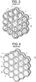
- This partition wall configuration 14 which is shown in Fig. 3 , is also referred to as a VECTORWALLTM configuration, as described in U.S. Patent No. 8,439,102 .
- a plurality of blocking tiles 12 can be installed in some of the hexagonal blocks 1 to restrict flow through predetermined portions of the partition wall assembly to define a bafflewall 15 (see, e.g., Fig. 4 ).
- the effectiveness of how well the secondary injected gas or air is distributed and mixed in the process stream governs the conversion effectiveness for the secondary flow, and, in turn, the overall conversion effectiveness of the entire chamber.
- these secondary injections are made at discreet single injection points, which insert the secondary gas into the process flow.
- the secondary injection of process gas or air was simply conveyed into the reaction chamber through simple ports located just downstream of the checkerwall structure 13 (see, e.g., Fig. 5 ) or, in the case of an overflow bafflewall, just at the overflow area of the baffle wall, as discussed above.
- These ports may or may not be configured with a nozzle to meter or otherwise somewhat control the injection and secondary flow, as dictated by the process considerations.
- a single injection point of this type does not efficiently distribute the secondary flow throughout the overall flow field in order to achieve optimal results.
- the present invention provides a refractory brick member, a refractory array and a method controlling distribution of secondary flow in a high temperature reaction furnace.
- a refractory brick member comprising a substantially tubular body having a first end, a second end opposed to the first end along a longitudinal length of the refractory brick member, a central bore extending from the first end to the second end along the longitudinal length thereof and defining an inner surface of the refractory brick member, and an outer surface extending from the first end to the second end along the longitudinal length thereof.
- the outer surface of the refractory brick member has a shape that transitions axially between a plurality of hexagonally-shaped portions and a plurality of non-hexagonally-shaped portions along the longitudinal length thereof.
- the first end preferably defines a first end face of the refractory brick member having a hexagonal cross-sectional shape
- the second end defines a second end face of the refractory brick member having a hexagonal cross-sectional shape
- the outer surface shape of the refractory brick member transitions axially between three hexagonally-shaped portions and two non- hexagonally-shaped portions. In another embodiment, the outer surface shape of the refractory brick member transitions axially between four hexagonally-shaped portions and three non-hexagonally-shaped portions.
- the non-hexagonally-shaped portions of the outer surface of the refractory brick member are cylindrical, a cross-sectional shape of the non-hexagonally-shaped portions of the outer surface is circular, and a cross-sectional shape of the hexagonally-shaped portions of the outer surface is hexagonal.
- the hexagonally-shaped portions of the outer surface of the refractory brick member further comprise at least one male interlocking mating member and one female interlocking mating member, disposed on adjacent side surfaces of the hexagonally-shaped portions with respect to one another.
- the refractory brick members according to the present invention also comprise at least one opening provided in a portion of the outer surface and in fluid communication with at least one of an end face and the central bore of the refractory brick member.
- the at least one opening comprises an opening in a portion of the outer surface of the refractory brick member passing from one of the non-hexagonally-shaped portions of the outer surface of the refractory brick member to the inner surface thereof (i.e., the central bore).
- the at least one opening passes from an outer surface of the end face of the refractory brick member, through the hexagonally-shaped portion of the outer surface to communicate with a plenum space defined by a non-hexagonally-shaped portion of the outer surface of the refractory brick member.
- the at least one opening is defined by an absence of at least one corner piece of an end face of the refractory brick member.
- the at least one opening according to any of the above aspects has a size in a range of 3,23 cm 2 (1/2 inches square) up to 19,36 cm 2 (3 inches square).
- an array comprising a plurality of refractory brick members, each refractory brick member comprising a substantially tubular body having a first end, a second end opposed to the first end along a longitudinal length of the refractory brick member, a central bore extending from the first end to the second end along the longitudinal length thereof and defining an inner surface of the refractory brick member, and an outer surface extending from the first end to the second end along the longitudinal length thereof.
- the outer surface of each refractory brick member has a shape that transitions axially between a plurality of hexagonally-shaped portions and a plurality of non-hexagonally-shaped portions along the longitudinal lengths thereof.
- the plurality of refractory brick members are arranged and interlocked with one another in a vertical and horizontal manner via mating members provided on the hexagonally-shaped portions of the respective outer surfaces thereof.
- the array also includes a continuous plenum space defined by the non-hexagonally-shaped portions of the outer surfaces of the respective refractory brick members arranged in the array.
- each refractory brick member comprises at least one opening provided in a portion of the outer surface thereof and in fluid communication with the plenum space and at least one of an end face of the refractory brick members and the central bore of the refractory brick members.
- a method for controlling distribution of secondary flow in a high temperature reaction furnace comprises the steps of providing a plenum assembly comprising a plurality of refractory brick members, each comprising a substantially tubular body having a first end, a second end opposed to the first end along a longitudinal length of the refractory brick member, a central bore extending from the first end to the second end along the longitudinal length thereof and defining an inner surface of the refractory brick member, and an outer surface extending from the first end to the second end along the longitudinal length thereof, wherein the outer surface of each refractory brick member has a shape that transitions axially between a plurality of hexagonally-shaped portions and a plurality of non-hexagonally-shaped portions along the longitudinal lengths thereof, and wherein the plurality of refractory brick members are arranged and interlocked with one another in a vertical and horizontal manner via mating members provided on the hexagonally-shaped portions of the outer surfaces thereof.
- the plenum assembly structure also includes a continuous plenum space defined by the non-hexagonally-shaped portions of the outer surfaces of the refractory brick members.
- the method further includes a step of injecting secondary air directly into the plenum space of the plenum assembly via one or more injection ports provided in fluid communication with the plenum space.
- the refractory brick members according to the present invention can be made of any type of refractory material, including ceramic materials.
- Alumina is preferred with respect to cost considerations and ease of manufacture.
- Other suitable examples include refractory ceramics such as mullite.
- the refractory bricks can be made many different conventional ceramic manufacturing processes such as slip casting, injection molding, and extrusion followed by machining, for example.
- a preferred method of forming the refractory bricks is Applicant's freeze cast process described in U.S. Patent No. 4,246,209 .
- the partition wall array (plenum assembly) configurations according to the present invention include a new type of refractory brick that can be deeper/longer than the prior art hexagonal blocks 1 (i.e., have lengths/depths ranging from 22,86 cm (9 inches) up to 60,96 cm (24 inches)), and which maintain a height to depth aspect ratio at less than 14: 1 for the purposes of stability.
- the outer shape transitions axially from hexagonal at the end face, to non-hexagonal, e.g., cylindrical, and back to hexagonal a plurality of times (see, e.g., Figs. 6A and 6B ).
- the cross-sectional shape of the hexagonal portions is hexagonal, whereas the cross-sectional shape of the cylindrical portions is circular.
- the refractory brick members according to the present invention stack and interlock in a similar manner as the continuously hexagonally-shaped block shown in Fig. 1 , however, when stacked in an array, the refractory brick members according to the present invention also beneficially provide a plenum space that is defined by the non-hexagonally-shaped portions of the outer surfaces thereof. That is, when the refractory brick members according to the present invention are stacked in an array to form a partition wall, also referenced to as a plenum assembly 7, this plenum space is continuous and interconnected through the height of the stack (see, e.g., Fig. 7 ).
- the plenum space is sealed around the outer periphery by the installation into a slot created in the hot face refractory, or by the refractory retention course formed by the use of conventional fire brick on either side in cases where the partition wall is constructed solely within the confines of the hot face lining.
- the use of compressed fiber between the partition wall and the constraining body, be it groove, or retaining ring, will not only create an expansion joint, but form a gasketed seal, as well.
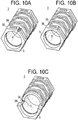
- the present invention utilizes this plenum formed by the non-hexagonally-shaped outer portions of the outer surface of the refractory brick members when the refractory brick members are stacked at installation to form an array for a partition wall structure to efficiently distribute secondary process gas or air that is injected into the plenum in a more uniform manner downstream of the partition wall assembly. That is, by connecting the secondary gas 20 injection to this plenum space 4 (see, e.g., Fig. 8 ), and providing one or more exits from the plenum space at a point in each refractory brick member (see, e.g., Fig. 9 and Figs. 10A- D ), the flow of the secondary injection gas 21 is distributed in a significantly more uniform manner, compared to the conventional single injection point method used in conjunction with partition walls that do not have any such plenum space.
- the plenum discharge points are defined, for example, by providing at least one hole (A) in the refractory brick member downstream face 5 passing through the first hexagonally- shaped section 3B, by removing one or more corners (B) of the refractory brick member downstream face 5 in the first hexagonally-shaped section 3B, or by providing one or more holes (C) passing from the non-hexagonally shaped portion 3 A of the outer surface into the central bore of the refractory brick member 3 (see, e.g., Fig. 9 and Figs. 10A-D ).
- the size and quantity of plenum space discharge openings per refractory brick member are determined so as to maintain a uniform secondary gas flow rate distribution across the entire plenum assembly 7.
- the shape of these openings is not limited, and can be round or be other shapes (such as the case where just the corner is broken).
- the size of the openings can range from 1,61 cm 2 (0,25 square inches) to over 19,36 cm 2 (3 square inches), for example.
- the individual plenum spaces, and thus the overall plenum space, must be sufficiently sized to allow for the passage of the secondary gas flow within the partition wall without being more constricting than the discharge points.
- the discharge points are the governing geometry that dictates the uniformity of the secondary gas flow through the plenum assembly and the preferred sizes described above. Dimensions applied in practice can be varied within the scope of the present invention as demanded by the furnace requirements and process parameters.
- Injection of the secondary gas stream 20 may be accomplished at a single location, or through multiple locations spaced around the circumference of the furnace, in communication with the plenum of the partition wall (i.e., plenum assembly) 7.
- the number of sites and introduction location of the secondary gas stream 20 is determined by the overall size of the partition wall and the volumetric flow rate of the gas 20, which is controlled by the processing parameters. That is, the rate of secondary gas injection is governed by the furnace procedures, and not by the plenum assembly 7 itself.
- the plenum assembly 7 serves as a distribution system, whereby the cross-sectional area of the exit points of the plenum facilitate even gas flow distribution, but do not restrict or govern the overall secondary gas flow rates.
- a length (depth) of each hexagonally-shaped outer section is 2,54 cm (1 inch) to 15,24 cm (6 inches), and a length (depth) of each non-hexagonally-shaped (e.g., cylindrical) outer section is 2,54 cm (1 inch) to 15,24 cm (6 inches).
- the overall length (depth) of the refractory brick members according to the present invention having the varying outer surface shapes can range from 22,86 cm (9 inches) to 60,96 cm (24 inches), as required by the specific demands of the individual furnace.
- the shape of the non- hexagonally-shaped portions of the outer surface is not limited to being cylindrical, but must be sufficiently different from the shape of the hexagonally-shaped portions in cross-section to provide the desired plenums 4A and plenum space 4 discussed below.
- the refractory brick members 2, 3 each also include a plurality of mechanical interlocking mating structures, such as the tongue and grove features t, g (tabs and groves) that interconnect with one another to stably provide an interlocking array plenum assembly 7, shown in Figs. 7-9 .
- the male mechanical mating members, tabs t are provided on adjacent side surfaces of the hexagonally-shaped portions 3B of the outer surface with respect to the female mating members, groves g.
- a plurality of spaces are formed by the non-contacting, non-hexagonally-shaped portions 3 A of the outer surfaces of the refractory brick members 3 when the refractory brick members are stacked to form the plenum assembly 7, as shown in Fig. 7 .
- Fig. 7 is a schematic perspective cut-away view showing a plurality of the interconnected plenums 4A that define the plenum space 4 (see, e.g., Fig. 8 ) when a plurality of refractory brick members 3 shown in Fig. 6B are stacked in an array to define the plenum assembly 7.
- this plenum space 4 is continuous and interconnected through the height of the stack in the plenum assembly 7, and the plenum space 4 is sealed around the outer periphery of the array by the installation slot in the hot face refractory, or by the refractory retention course in flush installations in the known manner, as described above.
- Fig. 8 is a schematic view showing the secondary injection of process gas or air 20 conveyed into the plenum space 4 through one or more ports located above or around the plenum assembly 7 according to the present invention.
- the plenum space 4 serves as a distribution system, whereby the cross-sectional area of the exit points of the plenum space 4 facilitate even flow distribution 21 of the secondary injected gas 20, but do not restrict or govern the overall secondary gas flow rates.
- the rate of secondary gas injection is governed by the furnace procedures, and not by the plenum assembly itself.
- Fig. 9 is an enlarged perspective view of a portion of the plenum assembly 7 shown in Fig. 7 , illustrating three different plenum discharge points (A), (B) and (C), and Figs. 10A- C are perspective views showing the individual refractory brick members 3 taken from Fig. 9 , showing the individual plenum discharge points (A), (B) and (C) in more detail.
- Fig. 10D shows another refractory brick member 3 having more than one plenum discharge point (B).
- plenum discharge point (A) is defined by providing at least one hole in the downstream end face 5 of the refractory brick members 3 passing through the first hexagonally-shaped portion 3B of the outer surface of the refractory brick member 3 and in fluid communication with the plenum space (i.e., the plenum associated with the cylindrical section 3A behind the first hexagonally-shaped section 3B).
- the shape of the plenum discharge point (A) is not strictly limited to being circular, and the opening defining the plenum space discharge point (A) can have any other shape.
- each plenum discharge point (A) has a size in a range of 3,23 cm 2 (1/2 inches square) up to about 19,36 cm 2 (3 inches square). If the size exceeds 19,36 cm 2 (three square inches), the proper distribution of gas within the partition wall will not be achieved. While it is not shown, it is understood that more than one plenum discharge point (A) could be provided in a single refractory brick member.
- Plenum discharge point (B) shown in Fig. 10B is defined by removing at least one corner of the downstream face 5 of the first hexagonally-shaped section of the refractory brick member 3 to define an outlet in fluid communication with the plenum space.
- Fig. 10D shows another example including more than one plenum discharge point (B), where each corner of the downstream end face 5 of the first hexagonal section 3B of the refractory brick member 3 is removed.
- Plenum discharge point(s) (B) can be formed by the simple mechanical process of breaking the corner or corners of the downstream end face 5 of the refractory brick member 3 before the array is formed, or by casting the desired shape or shapes into the individual refractory brick members 3 during the initial brick fabrication steps. It is preferred to remove the corners or form the openings (B) so that each opening (B) has a size in a range of 3,23 cm 2 (1/2 inches square) up to 19,36 cm 2 (3 inches square).
- Fig. IOC shows plenum discharge point (C), which is defined by providing at least one hole in the non-hexagonally-shaped portion 3 A of the outer surface of the refractory brick member 3, in fluid communication with the plenum space, passing into the central bore of the refractory brick member 3.
- This plenum discharge point (C) is provided before the refractory brick members 3 are stacked in the array to define the plenum assembly 7, and may be achieved by drilling the formed refractory brick member 3, or by casting the hole into the refractory brick member 3 during the initial brick fabrication steps.
- the size of each plenum discharge point (C) is also preferably 3,23 cm 2 (1/2 inches square) up to 19,36 cm 2 (3 inches square). While it is not shown, it is understood that more than one plenum discharge point (C) can be provided per refractory brick member.
- the flow of the secondary injection gas 21 is distributed in a significantly more uniform manner than when simply injected through a single point downstream of the partition wall, or even a plurality of points downstream of the partition wall in the conventional manner.
- the above staged reaction plenum partition wall design including the refractory brick members according to the present invention is applicable to any type of partition wall design, such as standard checkerwall configurations, where all of the hexagonal blocks have open unobstructed inside diameters (e.g., Fig. 2 ), bafflewall configurations, where some of the hexagonal blocks have blocked inside diameters as described above (e.g., Fig. 4 ), and VECTORWALLTM configurations (e.g., Fig. 3 ), where the downstream flow of each hexagonal block is turned by vectoring tiles provided in the downstream inside diameter of each hexagonal block, as described above.
- standard checkerwall configurations where all of the hexagonal blocks have open unobstructed inside diameters (e.g., Fig. 2 )
- bafflewall configurations where some of the hexagonal blocks have blocked inside diameters as described above (e.g., Fig. 4 )
- VECTORWALLTM configurations e.g., Fig. 3
Landscapes
- Engineering & Computer Science (AREA)
- Chemical & Material Sciences (AREA)
- Mechanical Engineering (AREA)
- General Engineering & Computer Science (AREA)
- Environmental & Geological Engineering (AREA)
- Chemical Kinetics & Catalysis (AREA)
- General Chemical & Material Sciences (AREA)
- Oil, Petroleum & Natural Gas (AREA)
- Health & Medical Sciences (AREA)
- Analytical Chemistry (AREA)
- Biomedical Technology (AREA)
- Organic Chemistry (AREA)
- Combustion & Propulsion (AREA)
- Inorganic Chemistry (AREA)
- Thermal Sciences (AREA)
- Physics & Mathematics (AREA)
- Ceramic Engineering (AREA)
- Dispersion Chemistry (AREA)
- Furnace Housings, Linings, Walls, And Ceilings (AREA)
Claims (14)
- Feuerfestes Ziegelelement, umfassend:
einen im Wesentlichen röhrenförmigen Körper mit einem ersten Ende, einem zweiten Ende, das dem ersten Ende entlang einer Längslänge des röhrenförmigen Körpers entgegengesetzt ist, einer Mittelbohrung, die sich vom ersten Ende zum zweiten Ende entlang der Längslänge erstreckt und eine Innenfläche des feuerfesten Ziegelelements und eine Außenfläche definiert, die sich vom ersten Ende zum zweiten Ende entlang der Längslänge erstreckt, wobei die Außenfläche des feuerfesten Ziegelelements eine Form aufweist, so dass Übergänge axial eine Vielzahl von abwechselnd sechseckig geformten Abschnitten (2B, 3B) und nicht sechseckig geformten Abschnitten (2A, 3A) entlang der Längslänge definieren, wobei die sechseckig geformten Abschnitte der Außenfläche des feuerfesten Ziegelelements ferner mindestens ein männliches zum Ineinandergreifen abgestimmtes Fügeelement und ein weibliches zum Ineinandergreifen abgestimmtes Fügeelement umfassen, die auf zueinander benachbarten Seitenflächen der sechseckig geformten Abschnitte der Außenfläche des feuerfesten Ziegelelements angeordnet sind, wodurch in dem Fall, dass eine Anordnung durch eine Vielzahl von feuerfesten Ziegelelementen gebildet wird, die über die auf den sechseckig geformten Abschnitten ihrer jeweiligen Außenflächen vorgesehenen Fügeelemente angeordnet und miteinander im Eingriff sind, die Anordnung einen durchgehenden Plenumraum umfasst, der durch die nicht sechseckig geformten Abschnitte der Außenflächen der jeweiligen feuerfesten Ziegelelemente definiert ist, die in der Anordnung angeordnet sind. - Feuerfestes Ziegelelement nach Anspruch 1, wobei die Außenfläche des feuerfesten Ziegelelements drei sechseckig geformte Abschnitte (2B) und zwei nicht sechseckig geformte Abschnitte (2A) umfasst.
- Feuerfestes Ziegelelement nach Anspruch 1, wobei die Außenfläche des feuerfesten Ziegelelements vier sechseckig geformte Abschnitte (3B) und drei nicht sechseckig geformte Abschnitte (3A) umfasst.
- Feuerfestes Ziegelelement nach Anspruch 1, wobei die nicht sechseckig geformten Abschnitte (2A, 3A) der Außenfläche des feuerfesten Ziegelelements zylindrisch sind.
- Feuerfestes Ziegelelement nach Anspruch 1, wobei eine Querschnittsform der nicht sechseckig geformten Abschnitte (2A, 3A) der Außenfläche des feuerfesten Ziegelelements kreisförmig ist.
- Feuerfestes Ziegelelement nach Anspruch 1, wobei das erste Ende eine erste Endfläche des feuerfesten Ziegelelements mit einer sechseckigen Querschnittsform definiert, und wobei das zweite Ende eine zweite Endfläche des feuerfesten Ziegelelements mit einer sechseckigen Querschnittsform definiert.
- Feuerfestes Ziegelelement nach Anspruch 1, ferner umfassend mindestens eine Öffnung, die in einem Abschnitt der Außenfläche des feuerfesten Ziegelelements bereitgestellt ist und mit mindestens einem der Folgenden in Kommunikation steht: einer Endfläche des feuerfesten Ziegelelements und der Mittelbohrung des feuerfesten Ziegelelements.
- Feuerfestes Ziegelelement nach Anspruch 7, wobei die mindestens eine Öffnung von einem der nicht sechseckig geformten Abschnitte der Außenfläche des feuerfesten Ziegelelements zu dessen Mittelbohrung verläuft.
- Feuerfestes Ziegelelement nach Anspruch 7, wobei die mindestens eine Öffnung von der Endfläche des feuerfesten Ziegelelements durch einen der sechseckig geformten Abschnitte der Außenfläche verläuft, um mit einem Plenumraum zu kommunizieren, der durch die nicht sechseckig geformten Abschnitte der Außenfläche des feuerfesten Ziegelelements definiert ist.
- Feuerfestes Ziegelelement nach Anspruch 7, wobei die mindestens eine Öffnung durch das Fehlen mindestens eines Eckstücks der Endfläche des feuerfesten Ziegelelements definiert ist.
- Feuerfestes Ziegelelement nach Anspruch 7, wobei die mindestens eine Öffnung eine Größe im Bereich von 3,23 cm2 (1/2 Quadratzoll) bis 19,36 cm2 (3 Quadratzoll) aufweist.
- Anordnung, umfassend:
eine Vielzahl von feuerfesten Ziegelelementen (3), wobei jedes feuerfeste Ziegelelement einen im Wesentlichen röhrenförmigen Körper mit einem ersten Ende, einem zweiten Ende, das dem ersten Ende entlang einer Längslänge des feuerfesten Ziegelelements entgegengesetzt ist, einer Mittelbohrung, die sich vom ersten Ende zum zweiten Ende entlang der genannten Längslänge erstreckt und eine Innenfläche des feuerfesten Ziegelelements und eine Außenfläche definiert, die sich vom ersten Ende zum zweiten Ende entlang der Längslänge erstreckt, wobei die Außenfläche jedes feuerfesten Ziegelelements eine Form aufweist, so dass Übergänge eine Vielzahl von sechseckig geformten Abschnitten (2B, 3B) und einer Vielzahl von nicht sechseckig geformten Abschnitten (2A, 3A) entlang der Längslängen definieren, und wobei die Vielzahl von feuerfesten Ziegelelementen (3) vertikal und horizontal angeordnet und miteinander über auf den sechseckig geformten Abschnitten ihrer Außenflächen bereitgestellten Fügeelemente im Eingriff ist; und einen durchgehenden Plenumraum (4A), der durch die nicht sechseckig geformten Abschnitte (2A, 3A) der Außenflächen der feuerfesten Ziegelelemente definiert ist, die in der Anordnung angeordnet sind. - Anordnung nach Anspruch 12, ferner umfassend mindestens eine Öffnung, die in einem Abschnitt der Außenfläche der feuerfesten Ziegelelemente bereitgestellt ist und in Fluidkommunikation mit dem Plenum (4A) und mindestens einem der Folgenden steht: einer Endfläche der feuerfesten Ziegelelements und der Mittelbohrung der feuerfesten Ziegelelements.
- Verfahren zum Steuern der Verteilung des Sekundärstroms in einem Hochtemperaturreaktionsofen, wobei das Verfahren die folgenden Schritte umfasst:Bereitstellen einer Plenumanordnung (7), die eine Vielzahl von feuerfesten Ziegelelementen (3) umfasst, wobei jedes feuerfeste Ziegelelement Folgendes umfasst: einen im Wesentlichen röhrenförmigen Körper mit einem mit einem ersten Ende, einem zweiten Ende, das dem ersten Ende entlang einer Längslänge des röhrenförmigen Körpers entgegengesetzt ist, einer Mittelbohrung, die sich vom ersten Ende zum zweiten Ende entlang der Längslänge erstreckt und eine Innenfläche des feuerfesten Ziegelelements und eine Außenfläche definiert, die sich vom ersten Ende zum zweiten Ende entlang der genannten Längslänge erstreckt, wobei die Außenfläche des feuerfesten Ziegelelements eine Form aufweist, so dass Übergänge zwischen einer Vielzahl von sechseckig geformten Abschnitten (2B, 3B) und einer Vielzahl von nicht sechseckig geformten Abschnitten (2A, 3A) entlang der genannten Längslänge definiert werden, und wobei die Vielzahl von feuerfesten Ziegelelementen (3) vertikal und horizontal angeordnet und miteinander über auf den sechseckig geformten Abschnitten ihrer Außenflächen vorgesehenen Fügeelemente im Eingriff ist; undeinen durchgehenden Plenumraum (4A), der durch die nicht sechseckig geformten Abschnitte (2A, 3A) der Außenflächen der feuerfesten Ziegelelemente definiert ist;wobei jedes feuerfeste Ziegelelement (3) mindestens eine Öffnung umfasst, die in einem Abschnitt der Außenfläche der feuerfesten Ziegelelemente bereitgestellt ist und in Fluidkommunikation mit dem Plenum (4A) und mindestens einem der Folgenden steht: einer Endfläche der feuerfesten Ziegelelemente (3) und der Mittelbohrung der feuerfesten Ziegelelemente; und Einblasen von Sekundärluft direkt in den Plenumraum (4A) der Plenumanordnung (7) über einen oder mehrere Einblasanschlüsse, die in Kommunikation mit dem Plenumraum vorgesehen sind.
Applications Claiming Priority (2)
| Application Number | Priority Date | Filing Date | Title |
|---|---|---|---|
| US201461925898P | 2014-01-10 | 2014-01-10 | |
| PCT/US2015/010598 WO2015105958A1 (en) | 2014-01-10 | 2015-01-08 | Staged reaction plenum partition wall for furnace |
Publications (3)
| Publication Number | Publication Date |
|---|---|
| EP3092455A1 EP3092455A1 (de) | 2016-11-16 |
| EP3092455A4 EP3092455A4 (de) | 2017-08-30 |
| EP3092455B1 true EP3092455B1 (de) | 2019-04-24 |
Family
ID=53524326
Family Applications (1)
| Application Number | Title | Priority Date | Filing Date |
|---|---|---|---|
| EP15735568.6A Active EP3092455B1 (de) | 2014-01-10 | 2015-01-08 | Plenumstrennwand mit stufenweiser reaktion für einen ofen |
Country Status (4)
| Country | Link |
|---|---|
| US (1) | US10190822B2 (de) |
| EP (1) | EP3092455B1 (de) |
| SA (1) | SA516371471B1 (de) |
| WO (1) | WO2015105958A1 (de) |
Families Citing this family (9)
| Publication number | Priority date | Publication date | Assignee | Title |
|---|---|---|---|---|
| USD781408S1 (en) * | 2013-04-11 | 2017-03-14 | Integrated Global Services, Inc. | Coated screen for large particle ash control |
| USD778423S1 (en) * | 2013-04-15 | 2017-02-07 | Integrated Global Services, Inc. | High surface area ash removal screen |
| WO2016017697A1 (ja) * | 2014-07-29 | 2016-02-04 | 京セラ株式会社 | 熱交換器 |
| US20170205156A1 (en) * | 2016-01-15 | 2017-07-20 | Hamilton Sundstrand Corporation | Heat exchangers |
| WO2018191592A1 (en) * | 2017-04-14 | 2018-10-18 | Blasch Precision Ceramics, Inc. | Retention mechanism for refractory inserts for reformer flue gas tunnel |
| EP3727665A4 (de) | 2017-12-20 | 2021-12-08 | BD Energy Systems, LLC | Mikro-reformer |
| CN109340806A (zh) * | 2018-06-26 | 2019-02-15 | 刘家良 | 一种直混烟气加热装置 |
| USD1048470S1 (en) * | 2022-12-09 | 2024-10-22 | Harbison Walker International Holdings, Inc. | Refractory anchor brick |
| USD1105492S1 (en) | 2023-08-15 | 2025-12-09 | Dakota BOLT | Hexagonal brick |
Family Cites Families (8)
| Publication number | Priority date | Publication date | Assignee | Title |
|---|---|---|---|---|
| US3087796A (en) * | 1960-05-31 | 1963-04-30 | Continental Carbon Co | Apparatus for making carbon black |
| US3088271A (en) * | 1961-02-06 | 1963-05-07 | Minnesota Mining & Mfg | Reaction milieu and afterburner incorporating same |
| US3376028A (en) | 1965-04-27 | 1968-04-02 | Central Electr Generat Board | Tubular recuperative heat exchangers with socket members joining tube sections end to end |
| US4246209A (en) | 1979-03-02 | 1981-01-20 | Ramu International | Freezing inorganic particulate slurries |
| US5954121A (en) | 1996-04-10 | 1999-09-21 | Blasch Precision Ceramics, Inc. | Refractory diffusor for industrial heat source |
| CA2443496C (en) * | 2003-09-30 | 2011-10-11 | Dana Canada Corporation | Tube bundle heat exchanger comprising tubes with expanded sections |
| US8439102B1 (en) * | 2008-08-25 | 2013-05-14 | Blasch Precision Ceramics | Vector tile, refractory assembly unit including same and refractory array including same |
| US8646515B2 (en) * | 2009-07-31 | 2014-02-11 | Blasch Precision Ceramics, Inc. | Ceramic ferrules and ceramic ferrule array including same for tube pitch variability tolerant process heat boiler system |
-
2015
- 2015-01-08 EP EP15735568.6A patent/EP3092455B1/de active Active
- 2015-01-08 US US15/107,545 patent/US10190822B2/en active Active
- 2015-01-08 WO PCT/US2015/010598 patent/WO2015105958A1/en not_active Ceased
-
2016
- 2016-07-08 SA SA516371471A patent/SA516371471B1/ar unknown
Non-Patent Citations (1)
| Title |
|---|
| None * |
Also Published As
| Publication number | Publication date |
|---|---|
| SA516371471B1 (ar) | 2021-04-07 |
| US20160320127A1 (en) | 2016-11-03 |
| WO2015105958A1 (en) | 2015-07-16 |
| EP3092455A1 (de) | 2016-11-16 |
| EP3092455A4 (de) | 2017-08-30 |
| US10190822B2 (en) | 2019-01-29 |
Similar Documents
| Publication | Publication Date | Title |
|---|---|---|
| US10190822B2 (en) | Staged reaction plenum partition wall for furnace | |
| CA1172987A (en) | System for improving the flow in the ducts between the regenerators or recuperators and the combustion chambers of industrial gas-fired systems, more particularly coke ovens | |
| KR102450538B1 (ko) | 개선된 폐가스 저감을 위한 시스템 및 방법 | |
| US11027251B2 (en) | Reformer flue gas tunnel and refractory components therefor | |
| WO2015154902A1 (en) | A burner tip and a burner for a gas turbine | |
| CN1997439A (zh) | 用于控制气体污染物燃烧的装置和方法 | |
| TW201714662A (zh) | 廢氣處理裝置 | |
| KR20120099226A (ko) | 고체 연료 버너 | |
| US20200173658A1 (en) | Refractory insert members and refractory block assembly including same | |
| CA3000162C (en) | Furnace tunnels and assembly system | |
| JP7191056B2 (ja) | ガス状汚染物の分解・酸化をコントロールする装置及びシステム | |
| EP3039370A1 (de) | Verbesserte blockkanalgeometrien und -anordnungen für regeneratoren thermischer verbrennungsvorrichtungen | |
| JP2017211100A (ja) | 排ガス処理装置 | |
| RU2715786C2 (ru) | Горелка для плавильного аппарата погружного горения | |
| CN108700287B (zh) | 用于喷射微粒状固体燃料和氧化剂的方法及其喷射器 | |
| CN105627312A (zh) | 将反应气体引入反应室的方法和装置 | |
| JP2007218458A (ja) | 旋回溶融炉を備えたボイラ構造 | |
| KR101434544B1 (ko) | 가스 배출 장치 및 이를 구비하는 코크스 생산 장치 | |
| CN220582450U (zh) | 一种酸性气焚烧炉的炉头衬里结构 | |
| JP5010828B2 (ja) | 焼却設備のダイオキシン類抑制方法 | |
| JP2015077545A (ja) | 粉体製造装置 | |
| CN117190194A (zh) | 气化-二燃一体式车载医疗废弃物处理装置 | |
| CN203771980U (zh) | 一种尾气沉灰室 | |
| JP6642802B2 (ja) | ガラス溶解炉 | |
| JP2010025375A (ja) | 熱交換器 |
Legal Events
| Date | Code | Title | Description |
|---|---|---|---|
| PUAI | Public reference made under article 153(3) epc to a published international application that has entered the european phase |
Free format text: ORIGINAL CODE: 0009012 |
|
| 17P | Request for examination filed |
Effective date: 20160701 |
|
| AK | Designated contracting states |
Kind code of ref document: A1 Designated state(s): AL AT BE BG CH CY CZ DE DK EE ES FI FR GB GR HR HU IE IS IT LI LT LU LV MC MK MT NL NO PL PT RO RS SE SI SK SM TR |
|
| AX | Request for extension of the european patent |
Extension state: BA ME |
|
| DAX | Request for extension of the european patent (deleted) | ||
| A4 | Supplementary search report drawn up and despatched |
Effective date: 20170801 |
|
| RIC1 | Information provided on ipc code assigned before grant |
Ipc: F28F 9/007 20060101ALI20170726BHEP Ipc: C01B 17/04 20060101ALI20170726BHEP Ipc: F28F 7/02 20060101ALI20170726BHEP Ipc: F23M 9/06 20060101ALI20170726BHEP Ipc: F23M 9/04 20060101ALI20170726BHEP Ipc: F28F 1/04 20060101AFI20170726BHEP |
|
| STAA | Information on the status of an ep patent application or granted ep patent |
Free format text: STATUS: EXAMINATION IS IN PROGRESS |
|
| 17Q | First examination report despatched |
Effective date: 20180627 |
|
| GRAP | Despatch of communication of intention to grant a patent |
Free format text: ORIGINAL CODE: EPIDOSNIGR1 |
|
| STAA | Information on the status of an ep patent application or granted ep patent |
Free format text: STATUS: GRANT OF PATENT IS INTENDED |
|
| INTG | Intention to grant announced |
Effective date: 20190110 |
|
| GRAS | Grant fee paid |
Free format text: ORIGINAL CODE: EPIDOSNIGR3 |
|
| GRAA | (expected) grant |
Free format text: ORIGINAL CODE: 0009210 |
|
| STAA | Information on the status of an ep patent application or granted ep patent |
Free format text: STATUS: THE PATENT HAS BEEN GRANTED |
|
| AK | Designated contracting states |
Kind code of ref document: B1 Designated state(s): AL AT BE BG CH CY CZ DE DK EE ES FI FR GB GR HR HU IE IS IT LI LT LU LV MC MK MT NL NO PL PT RO RS SE SI SK SM TR |
|
| REG | Reference to a national code |
Ref country code: GB Ref legal event code: FG4D |
|
| REG | Reference to a national code |
Ref country code: CH Ref legal event code: EP |
|
| REG | Reference to a national code |
Ref country code: AT Ref legal event code: REF Ref document number: 1124640 Country of ref document: AT Kind code of ref document: T Effective date: 20190515 Ref country code: IE Ref legal event code: FG4D |
|
| REG | Reference to a national code |
Ref country code: DE Ref legal event code: R096 Ref document number: 602015028882 Country of ref document: DE |
|
| REG | Reference to a national code |
Ref country code: NL Ref legal event code: FP |
|
| REG | Reference to a national code |
Ref country code: LT Ref legal event code: MG4D |
|
| PG25 | Lapsed in a contracting state [announced via postgrant information from national office to epo] |
Ref country code: NO Free format text: LAPSE BECAUSE OF FAILURE TO SUBMIT A TRANSLATION OF THE DESCRIPTION OR TO PAY THE FEE WITHIN THE PRESCRIBED TIME-LIMIT Effective date: 20190724 Ref country code: FI Free format text: LAPSE BECAUSE OF FAILURE TO SUBMIT A TRANSLATION OF THE DESCRIPTION OR TO PAY THE FEE WITHIN THE PRESCRIBED TIME-LIMIT Effective date: 20190424 Ref country code: SE Free format text: LAPSE BECAUSE OF FAILURE TO SUBMIT A TRANSLATION OF THE DESCRIPTION OR TO PAY THE FEE WITHIN THE PRESCRIBED TIME-LIMIT Effective date: 20190424 Ref country code: PT Free format text: LAPSE BECAUSE OF FAILURE TO SUBMIT A TRANSLATION OF THE DESCRIPTION OR TO PAY THE FEE WITHIN THE PRESCRIBED TIME-LIMIT Effective date: 20190824 Ref country code: AL Free format text: LAPSE BECAUSE OF FAILURE TO SUBMIT A TRANSLATION OF THE DESCRIPTION OR TO PAY THE FEE WITHIN THE PRESCRIBED TIME-LIMIT Effective date: 20190424 Ref country code: LT Free format text: LAPSE BECAUSE OF FAILURE TO SUBMIT A TRANSLATION OF THE DESCRIPTION OR TO PAY THE FEE WITHIN THE PRESCRIBED TIME-LIMIT Effective date: 20190424 Ref country code: HR Free format text: LAPSE BECAUSE OF FAILURE TO SUBMIT A TRANSLATION OF THE DESCRIPTION OR TO PAY THE FEE WITHIN THE PRESCRIBED TIME-LIMIT Effective date: 20190424 Ref country code: ES Free format text: LAPSE BECAUSE OF FAILURE TO SUBMIT A TRANSLATION OF THE DESCRIPTION OR TO PAY THE FEE WITHIN THE PRESCRIBED TIME-LIMIT Effective date: 20190424 |
|
| PG25 | Lapsed in a contracting state [announced via postgrant information from national office to epo] |
Ref country code: GR Free format text: LAPSE BECAUSE OF FAILURE TO SUBMIT A TRANSLATION OF THE DESCRIPTION OR TO PAY THE FEE WITHIN THE PRESCRIBED TIME-LIMIT Effective date: 20190725 Ref country code: RS Free format text: LAPSE BECAUSE OF FAILURE TO SUBMIT A TRANSLATION OF THE DESCRIPTION OR TO PAY THE FEE WITHIN THE PRESCRIBED TIME-LIMIT Effective date: 20190424 Ref country code: PL Free format text: LAPSE BECAUSE OF FAILURE TO SUBMIT A TRANSLATION OF THE DESCRIPTION OR TO PAY THE FEE WITHIN THE PRESCRIBED TIME-LIMIT Effective date: 20190424 Ref country code: BG Free format text: LAPSE BECAUSE OF FAILURE TO SUBMIT A TRANSLATION OF THE DESCRIPTION OR TO PAY THE FEE WITHIN THE PRESCRIBED TIME-LIMIT Effective date: 20190724 Ref country code: LV Free format text: LAPSE BECAUSE OF FAILURE TO SUBMIT A TRANSLATION OF THE DESCRIPTION OR TO PAY THE FEE WITHIN THE PRESCRIBED TIME-LIMIT Effective date: 20190424 |
|
| PG25 | Lapsed in a contracting state [announced via postgrant information from national office to epo] |
Ref country code: IS Free format text: LAPSE BECAUSE OF FAILURE TO SUBMIT A TRANSLATION OF THE DESCRIPTION OR TO PAY THE FEE WITHIN THE PRESCRIBED TIME-LIMIT Effective date: 20190824 |
|
| REG | Reference to a national code |
Ref country code: DE Ref legal event code: R097 Ref document number: 602015028882 Country of ref document: DE |
|
| PG25 | Lapsed in a contracting state [announced via postgrant information from national office to epo] |
Ref country code: CZ Free format text: LAPSE BECAUSE OF FAILURE TO SUBMIT A TRANSLATION OF THE DESCRIPTION OR TO PAY THE FEE WITHIN THE PRESCRIBED TIME-LIMIT Effective date: 20190424 Ref country code: RO Free format text: LAPSE BECAUSE OF FAILURE TO SUBMIT A TRANSLATION OF THE DESCRIPTION OR TO PAY THE FEE WITHIN THE PRESCRIBED TIME-LIMIT Effective date: 20190424 Ref country code: EE Free format text: LAPSE BECAUSE OF FAILURE TO SUBMIT A TRANSLATION OF THE DESCRIPTION OR TO PAY THE FEE WITHIN THE PRESCRIBED TIME-LIMIT Effective date: 20190424 Ref country code: DK Free format text: LAPSE BECAUSE OF FAILURE TO SUBMIT A TRANSLATION OF THE DESCRIPTION OR TO PAY THE FEE WITHIN THE PRESCRIBED TIME-LIMIT Effective date: 20190424 Ref country code: SK Free format text: LAPSE BECAUSE OF FAILURE TO SUBMIT A TRANSLATION OF THE DESCRIPTION OR TO PAY THE FEE WITHIN THE PRESCRIBED TIME-LIMIT Effective date: 20190424 |
|
| PG25 | Lapsed in a contracting state [announced via postgrant information from national office to epo] |
Ref country code: SM Free format text: LAPSE BECAUSE OF FAILURE TO SUBMIT A TRANSLATION OF THE DESCRIPTION OR TO PAY THE FEE WITHIN THE PRESCRIBED TIME-LIMIT Effective date: 20190424 |
|
| PLBE | No opposition filed within time limit |
Free format text: ORIGINAL CODE: 0009261 |
|
| STAA | Information on the status of an ep patent application or granted ep patent |
Free format text: STATUS: NO OPPOSITION FILED WITHIN TIME LIMIT |
|
| PG25 | Lapsed in a contracting state [announced via postgrant information from national office to epo] |
Ref country code: TR Free format text: LAPSE BECAUSE OF FAILURE TO SUBMIT A TRANSLATION OF THE DESCRIPTION OR TO PAY THE FEE WITHIN THE PRESCRIBED TIME-LIMIT Effective date: 20190424 |
|
| 26N | No opposition filed |
Effective date: 20200127 |
|
| PG25 | Lapsed in a contracting state [announced via postgrant information from national office to epo] |
Ref country code: SI Free format text: LAPSE BECAUSE OF FAILURE TO SUBMIT A TRANSLATION OF THE DESCRIPTION OR TO PAY THE FEE WITHIN THE PRESCRIBED TIME-LIMIT Effective date: 20190424 |
|
| PG25 | Lapsed in a contracting state [announced via postgrant information from national office to epo] |
Ref country code: MC Free format text: LAPSE BECAUSE OF FAILURE TO SUBMIT A TRANSLATION OF THE DESCRIPTION OR TO PAY THE FEE WITHIN THE PRESCRIBED TIME-LIMIT Effective date: 20190424 |
|
| REG | Reference to a national code |
Ref country code: CH Ref legal event code: PL |
|
| REG | Reference to a national code |
Ref country code: BE Ref legal event code: MM Effective date: 20200131 |
|
| PG25 | Lapsed in a contracting state [announced via postgrant information from national office to epo] |
Ref country code: LU Free format text: LAPSE BECAUSE OF NON-PAYMENT OF DUE FEES Effective date: 20200108 |
|
| PG25 | Lapsed in a contracting state [announced via postgrant information from national office to epo] |
Ref country code: LI Free format text: LAPSE BECAUSE OF NON-PAYMENT OF DUE FEES Effective date: 20200131 Ref country code: CH Free format text: LAPSE BECAUSE OF NON-PAYMENT OF DUE FEES Effective date: 20200131 Ref country code: BE Free format text: LAPSE BECAUSE OF NON-PAYMENT OF DUE FEES Effective date: 20200131 |
|
| PG25 | Lapsed in a contracting state [announced via postgrant information from national office to epo] |
Ref country code: IE Free format text: LAPSE BECAUSE OF NON-PAYMENT OF DUE FEES Effective date: 20200108 |
|
| REG | Reference to a national code |
Ref country code: AT Ref legal event code: UEP Ref document number: 1124640 Country of ref document: AT Kind code of ref document: T Effective date: 20190424 |
|
| PG25 | Lapsed in a contracting state [announced via postgrant information from national office to epo] |
Ref country code: MT Free format text: LAPSE BECAUSE OF FAILURE TO SUBMIT A TRANSLATION OF THE DESCRIPTION OR TO PAY THE FEE WITHIN THE PRESCRIBED TIME-LIMIT Effective date: 20190424 Ref country code: CY Free format text: LAPSE BECAUSE OF FAILURE TO SUBMIT A TRANSLATION OF THE DESCRIPTION OR TO PAY THE FEE WITHIN THE PRESCRIBED TIME-LIMIT Effective date: 20190424 |
|
| PG25 | Lapsed in a contracting state [announced via postgrant information from national office to epo] |
Ref country code: MK Free format text: LAPSE BECAUSE OF FAILURE TO SUBMIT A TRANSLATION OF THE DESCRIPTION OR TO PAY THE FEE WITHIN THE PRESCRIBED TIME-LIMIT Effective date: 20190424 |
|
| PGFP | Annual fee paid to national office [announced via postgrant information from national office to epo] |
Ref country code: FR Payment date: 20230125 Year of fee payment: 9 Ref country code: AT Payment date: 20230201 Year of fee payment: 9 |
|
| PGFP | Annual fee paid to national office [announced via postgrant information from national office to epo] |
Ref country code: IT Payment date: 20230221 Year of fee payment: 9 Ref country code: GB Payment date: 20230127 Year of fee payment: 9 Ref country code: DE Payment date: 20230127 Year of fee payment: 9 |
|
| PGFP | Annual fee paid to national office [announced via postgrant information from national office to epo] |
Ref country code: NL Payment date: 20230126 Year of fee payment: 9 |
|
| REG | Reference to a national code |
Ref country code: DE Ref legal event code: R119 Ref document number: 602015028882 Country of ref document: DE |
|
| REG | Reference to a national code |
Ref country code: NL Ref legal event code: MM Effective date: 20240201 |
|
| REG | Reference to a national code |
Ref country code: AT Ref legal event code: MM01 Ref document number: 1124640 Country of ref document: AT Kind code of ref document: T Effective date: 20240108 |
|
| GBPC | Gb: european patent ceased through non-payment of renewal fee |
Effective date: 20240108 |
|
| PG25 | Lapsed in a contracting state [announced via postgrant information from national office to epo] |
Ref country code: DE Free format text: LAPSE BECAUSE OF NON-PAYMENT OF DUE FEES Effective date: 20240801 |
|
| PG25 | Lapsed in a contracting state [announced via postgrant information from national office to epo] |
Ref country code: GB Free format text: LAPSE BECAUSE OF NON-PAYMENT OF DUE FEES Effective date: 20240108 |
|
| PG25 | Lapsed in a contracting state [announced via postgrant information from national office to epo] |
Ref country code: FR Free format text: LAPSE BECAUSE OF NON-PAYMENT OF DUE FEES Effective date: 20240131 |
|
| PG25 | Lapsed in a contracting state [announced via postgrant information from national office to epo] |
Ref country code: NL Free format text: LAPSE BECAUSE OF NON-PAYMENT OF DUE FEES Effective date: 20240201 |
|
| PG25 | Lapsed in a contracting state [announced via postgrant information from national office to epo] |
Ref country code: AT Free format text: LAPSE BECAUSE OF NON-PAYMENT OF DUE FEES Effective date: 20240108 |
|
| PG25 | Lapsed in a contracting state [announced via postgrant information from national office to epo] |
Ref country code: NL Free format text: LAPSE BECAUSE OF NON-PAYMENT OF DUE FEES Effective date: 20240201 Ref country code: GB Free format text: LAPSE BECAUSE OF NON-PAYMENT OF DUE FEES Effective date: 20240108 Ref country code: FR Free format text: LAPSE BECAUSE OF NON-PAYMENT OF DUE FEES Effective date: 20240131 Ref country code: DE Free format text: LAPSE BECAUSE OF NON-PAYMENT OF DUE FEES Effective date: 20240801 Ref country code: AT Free format text: LAPSE BECAUSE OF NON-PAYMENT OF DUE FEES Effective date: 20240108 |
|
| PG25 | Lapsed in a contracting state [announced via postgrant information from national office to epo] |
Ref country code: IT Free format text: LAPSE BECAUSE OF NON-PAYMENT OF DUE FEES Effective date: 20240108 |