EP3092919B2 - Dispositif de guidage pour le guidage d'une piece de meuble mobile par rapport à un corps de meuble - Google Patents
Dispositif de guidage pour le guidage d'une piece de meuble mobile par rapport à un corps de meuble Download PDFInfo
- Publication number
- EP3092919B2 EP3092919B2 EP16167026.0A EP16167026A EP3092919B2 EP 3092919 B2 EP3092919 B2 EP 3092919B2 EP 16167026 A EP16167026 A EP 16167026A EP 3092919 B2 EP3092919 B2 EP 3092919B2
- Authority
- EP
- European Patent Office
- Prior art keywords
- rail
- pinions
- guide device
- pull
- rack
- Prior art date
- Legal status (The legal status is an assumption and is not a legal conclusion. Google has not performed a legal analysis and makes no representation as to the accuracy of the status listed.)
- Active
Links
Images





Classifications
-
- F—MECHANICAL ENGINEERING; LIGHTING; HEATING; WEAPONS; BLASTING
- F16—ENGINEERING ELEMENTS AND UNITS; GENERAL MEASURES FOR PRODUCING AND MAINTAINING EFFECTIVE FUNCTIONING OF MACHINES OR INSTALLATIONS; THERMAL INSULATION IN GENERAL
- F16C—SHAFTS; FLEXIBLE SHAFTS; ELEMENTS OR CRANKSHAFT MECHANISMS; ROTARY BODIES OTHER THAN GEARING ELEMENTS; BEARINGS
- F16C29/00—Bearings for parts moving only linearly
- F16C29/005—Guide rails or tracks for a linear bearing, i.e. adapted for movement of a carriage or bearing body there along
-
- A—HUMAN NECESSITIES
- A47—FURNITURE; DOMESTIC ARTICLES OR APPLIANCES; COFFEE MILLS; SPICE MILLS; SUCTION CLEANERS IN GENERAL
- A47B—TABLES; DESKS; OFFICE FURNITURE; CABINETS; DRAWERS; GENERAL DETAILS OF FURNITURE
- A47B88/00—Drawers for tables, cabinets or like furniture; Guides for drawers
- A47B88/40—Sliding drawers; Slides or guides therefor
- A47B88/44—Sequencing or synchronisation of drawer slides or functional units
- A47B88/447—Simultaneous movement of rails within drawer slides, i.e. with a coordination of movement with all rail elements moving at the same time
-
- A—HUMAN NECESSITIES
- A47—FURNITURE; DOMESTIC ARTICLES OR APPLIANCES; COFFEE MILLS; SPICE MILLS; SUCTION CLEANERS IN GENERAL
- A47B—TABLES; DESKS; OFFICE FURNITURE; CABINETS; DRAWERS; GENERAL DETAILS OF FURNITURE
- A47B88/00—Drawers for tables, cabinets or like furniture; Guides for drawers
- A47B88/40—Sliding drawers; Slides or guides therefor
- A47B88/423—Fastening devices for slides or guides
- A47B88/427—Fastening devices for slides or guides at drawer side
-
- A—HUMAN NECESSITIES
- A47—FURNITURE; DOMESTIC ARTICLES OR APPLIANCES; COFFEE MILLS; SPICE MILLS; SUCTION CLEANERS IN GENERAL
- A47B—TABLES; DESKS; OFFICE FURNITURE; CABINETS; DRAWERS; GENERAL DETAILS OF FURNITURE
- A47B88/00—Drawers for tables, cabinets or like furniture; Guides for drawers
- A47B88/40—Sliding drawers; Slides or guides therefor
- A47B88/49—Sliding drawers; Slides or guides therefor with double extensible guides or parts
- A47B88/493—Sliding drawers; Slides or guides therefor with double extensible guides or parts with rollers, ball bearings, wheels, or the like
-
- F—MECHANICAL ENGINEERING; LIGHTING; HEATING; WEAPONS; BLASTING
- F16—ENGINEERING ELEMENTS AND UNITS; GENERAL MEASURES FOR PRODUCING AND MAINTAINING EFFECTIVE FUNCTIONING OF MACHINES OR INSTALLATIONS; THERMAL INSULATION IN GENERAL
- F16C—SHAFTS; FLEXIBLE SHAFTS; ELEMENTS OR CRANKSHAFT MECHANISMS; ROTARY BODIES OTHER THAN GEARING ELEMENTS; BEARINGS
- F16C29/00—Bearings for parts moving only linearly
- F16C29/04—Ball or roller bearings
-
- A—HUMAN NECESSITIES
- A47—FURNITURE; DOMESTIC ARTICLES OR APPLIANCES; COFFEE MILLS; SPICE MILLS; SUCTION CLEANERS IN GENERAL
- A47B—TABLES; DESKS; OFFICE FURNITURE; CABINETS; DRAWERS; GENERAL DETAILS OF FURNITURE
- A47B2210/00—General construction of drawers, guides and guide devices
- A47B2210/0002—Guide construction for drawers
- A47B2210/0013—Guide construction for drawers having a pinion on the intermediate drawer rail, between the upper and lower rail
-
- A—HUMAN NECESSITIES
- A47—FURNITURE; DOMESTIC ARTICLES OR APPLIANCES; COFFEE MILLS; SPICE MILLS; SUCTION CLEANERS IN GENERAL
- A47B—TABLES; DESKS; OFFICE FURNITURE; CABINETS; DRAWERS; GENERAL DETAILS OF FURNITURE
- A47B2210/00—General construction of drawers, guides and guide devices
- A47B2210/0002—Guide construction for drawers
- A47B2210/0029—Guide bearing means
- A47B2210/0037—Rollers
-
- A—HUMAN NECESSITIES
- A47—FURNITURE; DOMESTIC ARTICLES OR APPLIANCES; COFFEE MILLS; SPICE MILLS; SUCTION CLEANERS IN GENERAL
- A47B—TABLES; DESKS; OFFICE FURNITURE; CABINETS; DRAWERS; GENERAL DETAILS OF FURNITURE
- A47B2210/00—General construction of drawers, guides and guide devices
- A47B2210/0002—Guide construction for drawers
- A47B2210/0029—Guide bearing means
- A47B2210/0037—Rollers
- A47B2210/004—Rollers cages therefor, e.g. for telescopic slides
-
- A—HUMAN NECESSITIES
- A47—FURNITURE; DOMESTIC ARTICLES OR APPLIANCES; COFFEE MILLS; SPICE MILLS; SUCTION CLEANERS IN GENERAL
- A47B—TABLES; DESKS; OFFICE FURNITURE; CABINETS; DRAWERS; GENERAL DETAILS OF FURNITURE
- A47B2210/00—General construction of drawers, guides and guide devices
- A47B2210/0002—Guide construction for drawers
- A47B2210/0029—Guide bearing means
- A47B2210/0048—Pinion
-
- A—HUMAN NECESSITIES
- A47—FURNITURE; DOMESTIC ARTICLES OR APPLIANCES; COFFEE MILLS; SPICE MILLS; SUCTION CLEANERS IN GENERAL
- A47B—TABLES; DESKS; OFFICE FURNITURE; CABINETS; DRAWERS; GENERAL DETAILS OF FURNITURE
- A47B2210/00—General construction of drawers, guides and guide devices
- A47B2210/0002—Guide construction for drawers
- A47B2210/0051—Guide position
- A47B2210/0059—Guide located at the side of the drawer
-
- A—HUMAN NECESSITIES
- A47—FURNITURE; DOMESTIC ARTICLES OR APPLIANCES; COFFEE MILLS; SPICE MILLS; SUCTION CLEANERS IN GENERAL
- A47B—TABLES; DESKS; OFFICE FURNITURE; CABINETS; DRAWERS; GENERAL DETAILS OF FURNITURE
- A47B2210/00—General construction of drawers, guides and guide devices
- A47B2210/0002—Guide construction for drawers
- A47B2210/0064—Guide sequencing or synchronisation
- A47B2210/007—Three slide synchronisation
-
- A—HUMAN NECESSITIES
- A47—FURNITURE; DOMESTIC ARTICLES OR APPLIANCES; COFFEE MILLS; SPICE MILLS; SUCTION CLEANERS IN GENERAL
- A47B—TABLES; DESKS; OFFICE FURNITURE; CABINETS; DRAWERS; GENERAL DETAILS OF FURNITURE
- A47B2210/00—General construction of drawers, guides and guide devices
- A47B2210/0002—Guide construction for drawers
- A47B2210/0064—Guide sequencing or synchronisation
- A47B2210/0072—Coordinating mechanisms for sequential drawer slides, e.g. by cable
- A47B2210/0075—Coordinating mechanisms for sequential drawer slides, e.g. by cable using gears
-
- F—MECHANICAL ENGINEERING; LIGHTING; HEATING; WEAPONS; BLASTING
- F16—ENGINEERING ELEMENTS AND UNITS; GENERAL MEASURES FOR PRODUCING AND MAINTAINING EFFECTIVE FUNCTIONING OF MACHINES OR INSTALLATIONS; THERMAL INSULATION IN GENERAL
- F16C—SHAFTS; FLEXIBLE SHAFTS; ELEMENTS OR CRANKSHAFT MECHANISMS; ROTARY BODIES OTHER THAN GEARING ELEMENTS; BEARINGS
- F16C2314/00—Personal or domestic articles, e.g. household appliances such as washing machines, dryers
- F16C2314/70—Furniture
- F16C2314/72—Drawers
Definitions
- the invention relates to a guide device for guiding a furniture part that can be moved relative to a furniture body, in particular a drawer, a pull-out or the like, with at least one guide unit, which has a body rail that can be fastened to the furniture body, a center rail that is displaceably mounted relative to the body rail via lower rail guide means, and a via upper rail guide means relative to the middle rail and which can be connected to a drawer, wherein in addition to the lower rail guide means, lower rail support means are provided for supporting the middle rail on the carcass rail, and wherein in addition to the upper rail guide means upper Rail support means are provided for supporting the extension rail on the center rail.
- a guide unit of a guide device, or a furniture pull-out guide which has a body rail, a center rail and an extension rail, which are mounted so that they can be displaced relative to one another via rail guide means, is also referred to as a full extension.
- a standard full extension for example DE 20 2008 013242 U1
- an over-extraction for example DE 38 34 688 A1
- the furniture part moved with the guide device can be pulled out even further than with the standard full extension, with the extension rail being in the open position with its rear end at a distance in front of the front end of the cabinet rail.
- both the extension rail and the center rail lower more forwards in the direction of extension in runner systems with over-extension length than in runner systems without over-extension length.
- the middle rail can possibly lose its supporting role in relation to the extension rail and the cabinet rail, which can lead to collisions between the extension rail and the cabinet rail when it is being extended or retracted.
- the invention is therefore based on the object of providing a guide device which, compared to the conventional guide devices known from the prior art, is able to absorb higher weight and load forces, the lowering behavior of the guide device being reduced.
- this object is achieved with a guide device according to independent claim 1 .
- This task is at a management device.
- the type mentioned at the outset is solved according to the invention in that the lower rail support means and the upper rail support means are operatively connected to one another. Further developments of the invention result from the dependent claims.
- the center rail rolls over the lower rail support means relative to the carcass rail and the extension rail rolls over the upper rail support means relative to the center rail.
- the lower and upper rail support means carry out defined movements, that is to say that they assume defined positions relative to one another when the individual rails are in different extended positions, they are positively connected to one another. This positive control causes the lower rail supports to drive the upper rail supports and vice versa.
- the lower rail support means have a rack/pinion combination of at least one rack and at least one pinion that can be brought into meshing engagement or is in meshing engagement with the rack when it is being pulled in or out.
- a rack and pinion combination offers the advantage that very high forces can be transmitted with it and that the forces can be transmitted without play.
- both racks and pinions are relatively easy and inexpensive to produce and can be joined without tools.
- the pinion in the rack and pinion combination of the lower rail support means, is arranged on the middle rail and is rotatably supported there and the rack is arranged, molded or provided with the teeth pointing upwards on the lower rail support means. If the upper longitudinal edge of the lower rail support means is toothed, i.e. provided with teeth, no additional toothed rack is required, which therefore does not have to be attached to the lower rail support means and its weight can be saved.
- the upper rail support means have a rack/pinion combination of at least one rack and at least one pinion that can be brought into meshing engagement or is in meshing engagement with the rack when it is being pulled in or out.
- a rack and pinion combination also offers the advantage here that very high forces can be transmitted with it and that the forces can be transmitted without play.
- the pinion in the rack and pinion combination of the lower rail support means, is also arranged on the middle rail and is rotatably mounted there, and the rack is arranged, molded or provided with the teeth pointing downwards on the upper rail support means. If the lower longitudinal edge of the upper rail support means is toothed, i.e. provided with teeth, no additional toothed rack is required here either, which therefore does not have to be attached to the lower rail support means and whose weight can also be saved.
- the pinion of the rack and pinion combination of the lower rail support means and the pinion of the rack and pinion combination of the upper rail support means are operatively connected to one another. So there is a direct power and Path transmission from one to the other pinion. In addition, full synchronization can be implemented as a result.
- the two pinions are offset in height from one another. This ensures that one pinion only meshes with one rack and the other pinion only meshes with the other rack.
- the two pinions are driven by the racks and indirectly mesh with each other.
- the several transmission pinions have the advantage that they are inexpensive to produce, that they can be made of metal or plastic, that they are maintenance-free and that they can be easily mounted on a stub axle or that they have a stub axle that is rotatably mounted on the center rail .
- the two pinions are advantageously arranged in the same direction, or are driven in the same direction by the multiple transmission pinions.
- the multiple transmission pinions are disengaged from the toothed racks.
- the transmission pinions only serve to transmit the forces and moments from one pinion driven by the rack to the other pinion, which then drives its associated rack.
- the two pinions are designed to be synchronized. Both the forces and the moments of one rack are transferred fully synchronously to the other rack.
- An embodiment that does not belong to the invention provides that the two pinions are connected to one another via a chain or a toothed belt, with the pinions being designed as V-belt pulleys.
- the toothed belt is preferably designed as an externally toothed flat belt and is pressed onto the pinion by means of a deflection roller.
- a tensioning roller for the belt can also advantageously be provided.
- a preferred exemplary embodiment provides for the two pinions to be connected to one another via a reduction or transmission gear.
- the cabinet rail can be made shorter than the pull-out rail, for example.
- the pinions themselves can also have a different number of teeth.
- the invention also includes a piece of furniture with a furniture part that can be moved relative to a furniture body and is guided via a guide device, which is characterized by a guide device according to one of the claims.
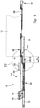
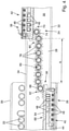
- the Figures 1 to 4 show a preferred exemplary embodiment of the guide device 10 according to the invention, which is shown as an example in use on a furniture part 12 designed as a drawer.
- a furniture part 12 designed as a drawer.
- pull-outs such as tray pull-outs, cupboard pull-outs or the like.
- the guide device 10 according to the invention is explained using the example of a drawer.
- the drawer is slidably mounted by means of the guide device 10 relative to a furniture body, not shown.
- the guide device 10 comprises at least one guide unit 14, in particular two guide units 14, which act on opposite side surfaces of the drawer. Only a single guide unit 14 is shown in the drawing, but the other guide unit associated with the opposite side surface of the drawer is constructed in a corresponding manner.
- the guide units 14 each have a body rail 16 which is designed, for example, as a bent sheet metal component.
- the cabinet rail 16 has a cabinet bracket 18 for fastening, which has at least one mounting leg 20, which has a plurality of fastening openings 22, for example arranged in rows one behind the other, via which the cabinet bracket 18 is positioned with the aid of suitable fastening means on an associated side wall of a drawer receptacle formed in the furniture cabinet can be attached.
- the body bracket 18 has a support section protruding at an angle from the mounting leg 20, on which a center rail 24, which also belongs to the guide unit 14, is guided in a displaceable manner in a manner that will be described below.
- the middle rail 24 is mounted displaceably relative to the body rail 16 via lower rail guide means 26 .
- the middle rail 24 is expediently also designed as a sheet metal profile, in particular with a U-shaped cross section.
- the middle rail 24 has a base section 28 which is vertically aligned when the guide device 10 is in the installed state and which has a flat front side 30 and a flat rear side opposite this, facing the mounting leg 20 of the carcass bracket 18 (away from the viewer).
- Two leg sections 32 , 34 running essentially parallel to one another are integrally formed on the base section 28 and each run in the region of the rear side of the base section 28 .
- leg sections 32, 34 form running surfaces for the lower rail guide means 26 and also for the upper rail guide means 36, the middle rail 24 being linearly displaceably mounted on a pull-out rail 38 via the latter.
- the lower and upper rail guides 26, 36 each have at least one roller carriage 40, 42.
- the lower rail guides 26 are assigned a lower roller carriage 40 and the upper rail guides 36 are assigned an upper roller carriage 42.
- the lower roller carriage 40 has a carriage housing 44 associated with the lower leg portion 32 .
- the carriage body 44 is conveniently made of plastics material.
- the carriage housing 44 extends along the lower leg section 32.
- a plurality of rollers 46 are accommodated in the carriage housing 44 and are rotatably mounted there via suitable bearing means.
- the rollers 46 are expediently grouped in several groups of rollers to form several rollers 46 each.
- the axes of rotation of the rollers 46 extend in the plane of the associated lower leg section 32.
- Each group of rollers has a plurality of upper rollers and a plurality of lower rollers 46.
- the upper rollers 46 of a roller group are arranged one behind the other in the longitudinal direction, with their axes of rotation being aligned parallel to one another.
- the upper rollers 46 of a group of rollers run with their running surfaces on the upper side of the associated lower leg section 32 .
- the lower rollers 46 of a group of rollers are opposite the upper rollers 46 of the same group of rollers, namely always in pairs an upper roller 46 opposite a lower roller 46, with the associated lower leg section 32 being accommodated between the upper and lower rollers .
- the lower rollers 46 of a group of rollers run with their running surfaces on the underside of the associated lower leg section 32 of the center rail 24 .
- a plurality of roller groups arranged one behind the other in the longitudinal direction of the rails are formed on the lower roller carriage 40 and each have upper and lower rollers 46 .
- the arrangement of the upper and lower rollers 46 of the other groups of rollers is the same as that of the group of rollers described above.
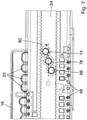
- the figure 3 shows in particular the upper roller carriage 42, via which the pull-out rail 38 is mounted so as to be linearly displaceable with respect to the middle rail 24.
- the upper roller carriage 42 is assigned to the upper leg section 34 of the center rail 24 .
- the upper rollers 46 of the upper roller carriage 42 run on the upper side of the upper leg section 34 .
- the lower rollers 46 of the upper roller carriage 42 run on the underside of the upper leg section 34 .
- the upper leg portion 34 is thus in turn received between the upper and lower rollers 46 of the roller group.
- the lower and upper roller carriages 40, 42 are independently movable.
- the lower rollers 46 of a respective group of rollers of the lower roller carriage 40 run on the underside of the lower leg section 32 . Furthermore, these lower rollers 46 run on an assigned running surface of the carcass rail 16 .
- the lower roller carriage 40 is mounted so that it can be displaced relative to both the body rail 16 and the middle rail 24 .
- the upper rollers 46 of a respective group of rollers of the upper roller carriage 42 run on the upper side of the upper leg section 34 . At the same time, they run off an associated running surface of the pull-out rail 38 .
- both the lower and the upper roller carriage 40, 42 have support rollers 48 which are rotatably mounted in the respective carriage housings 44 and whose axes of rotation are aligned perpendicularly to the axes of rotation of the rollers 46, i.e. lie in the plane of the base section 28 of the middle rail 24.
- the support rollers 48 on the upper roller carriage 42 run on an assigned running surface on the pull-out rail 38 and ensure lateral stabilization of the upper roller carriage 42.
- the support rollers 48 on the lower roller carriage 40 are assigned to a corresponding running surface on the body rail 16 and run there and thus ensure for lateral stabilization of the lower roller carriage 40.
- the pull-out rail 38 is guided in a linearly displaceable manner to the center rail 24 via the upper rail guide means 36 .
- the pull-out rail 38 can be inserted between an in figure 1 shown extended position 50 and in figure 2 shown retracted position 52 move.
- the pull-out rail 38 which in the example could also be referred to as a drawer rail, is coupled to the drawer via coupling means, in particular via latching means.
- the guide unit 14 is designed according to the invention as an over-extension.
- a rear end 54 of the extension rail 38 in the extension direction of the extension rail 38 is positioned at a distance A in front of a front end 56 of the carcass rail 16 .
- Rail support means 58, 60 are provided to prevent the pull-out rail 38 and the center rail 24 from lowering, which is particularly harmful to the guiding behavior of the guide unit 14, especially when the drawer is heavily loaded.
- Lower rail support means 58 are provided to support center rail 24 on body rail 16 .
- upper rail support means 60 are also provided for supporting the extension rail 38 on the center rail 24.
- the lower rail support means 58 interact with the lower rail guide means 26 and the upper rail support means 60 with the upper rail guide means 36 .
- the lower rail support means 58 have a rack/pinion combination 62, which in the example has a rack 64 and at least one pinion 66 that can be brought into or is in meshing engagement with the rack 64 when retracting or extending.
- the pinion 66 is located on the front side 30 of the base section 28 of the center rail 24 and is rotatably mounted there via suitable bearing means.
- the rack 64 associated with the pinion 66 is arranged on the lower rail guide means 26 with the toothing 68 pointing upwards.
- the toothed rack 64 is expediently located on the carriage housing 44 of the lower roller carriage 40.
- the toothed rack 64 can, for example, be connected to the carriage housing 44 as a separate component or, as shown in the example, be molded on at the same time during the manufacture of the carriage housing 44, which is made of plastic material in particular.
- the upper rail support means 60 also includes a rack and pinion 70 combination.
- a toothed rack 72 and an associated pinion 74 are also provided here.
- the pinion 74 of the upper rail support means 60 is also arranged on the front side 30 of the base section 28 of the middle rail 24 and is rotatably supported there by suitable bearing means.
- the associated toothed rack 72 is arranged on the upper rail guide means 36, namely on the carriage housing 44 of the upper roller carriage 42, as in particular in figure 3 shown.
- the rack 72 has downwardly facing teeth 76.
- the pinion 74 is rotatably mounted on the base portion 28 of the center rail 24 by suitable bearing means and meshes with the downwardly directed teeth 76 of the associated rack 72 formed on the carriage body 28.
- the two pinions 66 and 74 are offset in height from each other and that in addition to the two pinions 66 and 74 rotatably attached to the center rail 24, there are also several, seven in the illustrated embodiment, i.e. an odd number of transmission pinions 78 that are also are rotatably mounted on the center rail 24.
- the transmission pinions 78 lie in a line 80 which has the same distance from the pinion 66 as for the pinion 74 . Therewith the transmission pinions 78 touch neither the rack 64 nor the rack 72. In addition, the transmission pinions 78 lie between the two pinions 66 and 74 and mesh with them. As a result, the two pinions 66 and 74 are driven in opposite directions.
- the pull-out rail 38 is moved in the direction of the extended position 50 when the drawer is pulled out or extended.
- the toothed rack 72 provided on the upper roller carriage 42 moves on the associated pinion 74 .
- the pinion 66 which is also arranged on the middle rail 24, meshes with the assigned rack 64, which is arranged on the lower roller carriage 40 and has the teeth 68 pointing upwards.
- the racks 64 and 72 therefore perform opposite movements. From a certain extension distance, the extension rail 38 leaves the area of the cabinet rail 16, so that it is overextended.
- the extended position 50 shown remains the pinion 66 arranged on the center rail 24 in engagement with the associated toothed rack 64 on the lower roller carriage 40, as a result of which the center rail 24 can be supported on the lower roller carriage 40 on the body rail 16.
- the pull-out rail 38 is supported on the center rail 24 via the toothed rack 76 and the associated pinion 74 . Since the center rail 24 is supported on the cabinet rail 16, as mentioned above, the pull-out rail 38 is also supported on the cabinet rail 16 via the center rail 24. The lowering behavior when extending the pull-out rail 38 and the center rail 24 can thus be reduced. Because the guide device 10 has two identically constructed guide units 14 and the pinions 66 and 74 mesh with one another via transmission pinions 78, the identically constructed rack/pinion combinations 62, 70 on both guide units 14 can achieve full synchronization during the guide.
- the Figures 5 to 8 show an embodiment not belonging to the invention, in which the same components are named the same and have the same reference symbols.
- the guide device 10 has a body rail 16, a middle rail 24 and a pull-out rail 38, with which a furniture part 12 can also be extended from a body, with the guide unit 14 also being designed as an over-extension.
- a rear end 54 of the extension rail 38 in the extension direction of the extension rail 38 is positioned at a distance A′ in front of a front end 56 of the carcass rail 16 .
- This distance A ' is less than the distance A in the Figures 1 to 4 shown embodiment.
- This smaller distance A' is caused by the fact that only a single transmission pinion 78 is provided between the pinions 66 and 74, this one transmission pinion 78 also being arranged on the center rail 24 in the line 80 between the two pinions 66 and 74 and with these combs.
- a defined over-extension can thus be implemented with fully synchronized guide units 14, with heavy furniture parts 12 also being supported and high weight and loading forces being absorbed in such a way that the extension rail 38 does not lower.
Landscapes
- Engineering & Computer Science (AREA)
- General Engineering & Computer Science (AREA)
- Mechanical Engineering (AREA)
- Drawers Of Furniture (AREA)
Claims (9)
- Dispositif de guidage (10) pour le guidage d'une pièce de meuble (12) mobile par rapport à un corps de meuble, en particulier d'un tiroir, d'une rallonge ou similaires, avec au moins une unité de guidage (14) qui présente un rail de corps (16) pouvant être fixé sur le corps de meuble, un rail médian (24) logé de manière mobile par le biais de moyens de guidage de rail (26) inférieurs par rapport au rail de corps (16) et un rail de rallonge (38) pouvant être relié à une rallonge, logé de manière mobile par le biais de moyens de guidage de rail (36) supérieurs par rapport au rail médian (24), dans lequel outre les moyens de guidage de rail (26) inférieurs des moyens d'appui de rail (58) inférieurs sont prévus pour l'appui du rail médian (24) sur le rail de corps (16), et dans lequel outre les moyens de guidage de rail (36) supérieurs des moyens d'appui de rail (60) supérieurs sont prévus pour l'appui du rail de rallonge (38) sur le rail médian (24), dans lequel les moyens d'appui de rail (58) inférieurs et les moyens d'appui de rail (60) supérieurs sont reliés activement entre eux, et dans lequel l'unité de guidage (14) est réalisée en tant que surrallonge, dans lequel dans une position de sortie (50) une extrémité (54) arrière dans le sens de sortie du rail de rallonge (38) du rail de rallonge (38) est positionnée à distance A avant une extrémité avant (56) du rail de corps (16), dans lequel les moyens d'appui de rail inférieurs et supérieurs (58, 60) présentent respectivement une combinaison de crémaillère/pignon (62, 70) d'au moins une crémaillère (64, 72) et d'au moins un pignon (66, 74) pouvant être amené en prise engrenante ou se trouvant en prise engrenante avec la crémaillère (64, 72) lors de l'entrée ou la sortie agencé sur le rail médian (24) et logé de manière rotative là-bas, dans lequel les deux pignons (66, 74) sont reliés activement l'un à l'autre, caractérisé en ce que la crémaillère (64) des moyens d'appui de rail (58) inférieurs est agencée avec une denture dirigée vers le haut sur les moyens de guidage de rail (26) inférieurs et la crémaillère (72) des moyens d'appui de rail (60) supérieurs est agencée avec la denture (76) dirigée vers le bas sur les moyens de guidage de rail supérieurs, et dans lequel un nombre impair de plusieurs pignons de transmission (78) est intercalé entre les deux pignons (66, 74).
- Dispositif de guidage selon la revendication 1, caractérisé en ce que les deux pignons (66, 74) sont agencés en déport vertical l'un de l'autre.
- Dispositif de guidage selon la revendication 1 ou 2, caractérisé en ce que les deux pignons (66, 74) sont entraînés et s'engrènent indirectement l'un avec l'autre, dans lequel de préférence les deux pignons (66, 74) sont entraînés par des crémaillères (64, 72).
- Dispositif de guidage selon la revendication 3, caractérisé en ce que des pignons de transmission (78) s'engrenant entre eux et se trouvant les uns à côté des autres sont agencés à l'opposé.
- Dispositif de guidage selon la revendication 4, caractérisé en ce que les plusieurs pignons de transmission (78) sont mis hors prise des crémaillères (64, 72).
- Dispositif de guidage selon l'une quelconque des revendications précédentes, caractérisé en ce que les deux pignons (66, 74) sont agencés dans le même sens.
- Dispositif de guidage selon l'une quelconque des revendications précédentes, caractérisé en ce que les deux pignons (66, 74) sont réalisés de manière synchronisée.
- Dispositif de guidage selon l'une quelconque des revendications précédentes, caractérisé en ce que les deux pignons (66, 74) sont reliés entre eux par un engrenage de réduction ou de multiplication.
- Meuble avec une pièce de meuble (12) guidée par le biais d'un dispositif de guidage (10), mobile par rapport à un corps de meuble, caractérisé en ce que le dispositif de guidage (10) est réalisé selon l'une quelconque des revendications précédentes.
Applications Claiming Priority (1)
| Application Number | Priority Date | Filing Date | Title |
|---|---|---|---|
| DE202015003469.1U DE202015003469U1 (de) | 2015-05-09 | 2015-05-09 | Führungseinrichtung zur Führung eines relativ zu einem Möbelkorpus bewegbaren Möbelteils |
Publications (3)
| Publication Number | Publication Date |
|---|---|
| EP3092919A1 EP3092919A1 (fr) | 2016-11-16 |
| EP3092919B1 EP3092919B1 (fr) | 2018-12-19 |
| EP3092919B2 true EP3092919B2 (fr) | 2022-01-19 |
Family
ID=55809043
Family Applications (1)
| Application Number | Title | Priority Date | Filing Date |
|---|---|---|---|
| EP16167026.0A Active EP3092919B2 (fr) | 2015-05-09 | 2016-04-26 | Dispositif de guidage pour le guidage d'une piece de meuble mobile par rapport à un corps de meuble |
Country Status (4)
| Country | Link |
|---|---|
| US (1) | US20160324318A1 (fr) |
| EP (1) | EP3092919B2 (fr) |
| CN (1) | CN206119713U (fr) |
| DE (1) | DE202015003469U1 (fr) |
Families Citing this family (7)
| Publication number | Priority date | Publication date | Assignee | Title |
|---|---|---|---|---|
| TWI539916B (zh) * | 2015-11-12 | 2016-07-01 | 川湖科技股份有限公司 | 滑軌總成及其助滑裝置 |
| CN106451186B (zh) * | 2016-12-08 | 2017-12-12 | 盐城中咏投资发展有限公司 | 一种抽屉式电力安装柜装置 |
| AT519982B1 (de) * | 2017-08-17 | 2018-12-15 | Blum Gmbh Julius | Schubladenausziehführung |
| TWI698202B (zh) * | 2019-04-23 | 2020-07-11 | 川湖科技股份有限公司 | 滑軌總成 |
| CN111839037B (zh) * | 2019-04-24 | 2022-02-22 | 川湖科技股份有限公司 | 滑轨总成 |
| DE102024000334A1 (de) * | 2024-02-02 | 2025-08-07 | Anton Schneider Gmbh & Co Kg | Auszugführung für ein Schubelement |
| TWI887165B (zh) * | 2024-11-19 | 2025-06-11 | 川湖科技股份有限公司 | 托架總成 |
Citations (1)
| Publication number | Priority date | Publication date | Assignee | Title |
|---|---|---|---|---|
| CH559530A5 (fr) † | 1973-02-12 | 1975-03-14 | Merz Meyer Ag |
Family Cites Families (11)
| Publication number | Priority date | Publication date | Assignee | Title |
|---|---|---|---|---|
| US3124401A (en) * | 1964-03-10 | Drawer slide mechanism | ||
| US2174181A (en) * | 1938-11-05 | 1939-09-26 | Remington Rand Inc | Overtravel drawer support |
| AT365433B (de) * | 1980-05-06 | 1982-01-11 | Blum Gmbh Julius | Vollauszugeinrichtung, insbesondere fuer schubladen |
| DE3834688A1 (de) * | 1988-05-18 | 1989-11-30 | Schock Metallwerk | Synchronisierte vollauszugfuehrung |
| DE3942974A1 (de) * | 1989-12-23 | 1991-06-27 | Grass Ag | Schubladenfuehrung mit vollauszug |
| NL1003665C2 (nl) * | 1996-07-23 | 1998-01-28 | Thomas Regout B V | Overuittrekbare diferentiële ladegeleider. |
| EP1516563A1 (fr) * | 2003-09-18 | 2005-03-23 | Grass GmbH | Palier linéaire à rouleaux |
| DE202008013242U1 (de) * | 2008-10-08 | 2009-05-20 | Grass Gmbh | Vorrichtung mit einer Führungseinheit zur Führung eines relativ zu einem Korpus bewegbaren Möbelauszugs |
| DE202010007999U1 (de) * | 2010-07-07 | 2010-10-07 | Anton Schneider Gmbh & Co Kg | Ausziehführung für Schubladen |
| DE202010011854U1 (de) * | 2010-08-25 | 2011-11-28 | Grass Gmbh | Führungseinheit für ein bewegliches Möbelelement |
| AT511589B1 (de) * | 2011-11-16 | 2013-01-15 | Blum Gmbh Julius | Ausziehführung für eine schublade |
-
2015
- 2015-05-09 DE DE202015003469.1U patent/DE202015003469U1/de not_active Expired - Lifetime
-
2016
- 2016-04-26 EP EP16167026.0A patent/EP3092919B2/fr active Active
- 2016-05-09 CN CN201620409838.0U patent/CN206119713U/zh not_active Expired - Lifetime
- 2016-05-09 US US15/149,385 patent/US20160324318A1/en not_active Abandoned
Patent Citations (1)
| Publication number | Priority date | Publication date | Assignee | Title |
|---|---|---|---|---|
| CH559530A5 (fr) † | 1973-02-12 | 1975-03-14 | Merz Meyer Ag |
Also Published As
| Publication number | Publication date |
|---|---|
| CN206119713U (zh) | 2017-04-26 |
| DE202015003469U1 (de) | 2016-08-15 |
| EP3092919B1 (fr) | 2018-12-19 |
| EP3092919A1 (fr) | 2016-11-16 |
| US20160324318A1 (en) | 2016-11-10 |
Similar Documents
| Publication | Publication Date | Title |
|---|---|---|
| EP3092919B2 (fr) | Dispositif de guidage pour le guidage d'une piece de meuble mobile par rapport à un corps de meuble | |
| EP2916688B1 (fr) | Glissière télescopique de tiroir | |
| EP2538818B1 (fr) | Guidage d'extraction pour tiroirs | |
| AT508988B1 (de) | Schubladenausziehführung | |
| EP3183997B1 (fr) | Dispositif de guidage pour le guidage d'une pièce de meuble mobile par rapport à un corps de meuble | |
| EP3838068A1 (fr) | Guidage d'extension de tiroir | |
| AT518049B1 (de) | Schubladenanordnung | |
| EP1470770A1 (fr) | Ensemble de guidage pour glissières de tiroirs | |
| EP2979581B1 (fr) | Dispositif de guidage pour le guidage d'une piece de meuble mobile par rapport a un corps de meuble | |
| EP3676505A1 (fr) | Glissière de sortie de tiroir | |
| EP3498131B1 (fr) | Guidage d'extraction | |
| EP2422650A1 (fr) | Unité de guidage pour un élément de meuble mobile | |
| AT517479B1 (de) | Schubladenausziehführung | |
| EP4385363A2 (fr) | Ensemble comprenant un dispositif d'entraînement et un dispositif de synchronisation pour glissières télescopiques d'un tiroir | |
| AT520691B1 (de) | Führungssystem | |
| EP2716182B1 (fr) | Guidage d'extraction pour un élément de meuble pouvant être extrait d'un corps de meuble | |
| AT520673B1 (de) | Bewegungsmechanismus für ein Führungssystem | |
| DE102020105225A1 (de) | Auszugsführung | |
| AT10101U1 (de) | Vorrichtung mit einer führungseinheit zur führung eines relativ zu einem korpus beweglichen möbelauszugs und möbel | |
| EP0809956A2 (fr) | Dispositif à tiroirs pour un élément coulissant, encastrable dans une unité d'armoire | |
| EP3682764B1 (fr) | Dispositif de guidage pour le guidage d'une pièce de meuble mobile par rapport à un corps de meuble | |
| EP1449460B1 (fr) | Rail de guidage, en particulier pour meubles de cuisine | |
| AT501907B1 (de) | Seitenführung für ein aus einem hochschrankkorpus ausziehbares hochschrankteil | |
| DE20321394U1 (de) | Unterbodenausziehführung für ausziehbare Möbelteile | |
| DE202011051600U1 (de) | Schieberegal |
Legal Events
| Date | Code | Title | Description |
|---|---|---|---|
| PUAI | Public reference made under article 153(3) epc to a published international application that has entered the european phase |
Free format text: ORIGINAL CODE: 0009012 |
|
| AK | Designated contracting states |
Kind code of ref document: A1 Designated state(s): AL AT BE BG CH CY CZ DE DK EE ES FI FR GB GR HR HU IE IS IT LI LT LU LV MC MK MT NL NO PL PT RO RS SE SI SK SM TR |
|
| AX | Request for extension of the european patent |
Extension state: BA ME |
|
| STAA | Information on the status of an ep patent application or granted ep patent |
Free format text: STATUS: REQUEST FOR EXAMINATION WAS MADE |
|
| 17P | Request for examination filed |
Effective date: 20170516 |
|
| RBV | Designated contracting states (corrected) |
Designated state(s): AL AT BE BG CH CY CZ DE DK EE ES FI FR GB GR HR HU IE IS IT LI LT LU LV MC MK MT NL NO PL PT RO RS SE SI SK SM TR |
|
| STAA | Information on the status of an ep patent application or granted ep patent |
Free format text: STATUS: EXAMINATION IS IN PROGRESS |
|
| 17Q | First examination report despatched |
Effective date: 20171018 |
|
| REG | Reference to a national code |
Ref country code: DE Ref legal event code: R079 Ref document number: 502016002878 Country of ref document: DE Free format text: PREVIOUS MAIN CLASS: A47B0088100000 Ipc: A47B0088493000 |
|
| GRAP | Despatch of communication of intention to grant a patent |
Free format text: ORIGINAL CODE: EPIDOSNIGR1 |
|
| STAA | Information on the status of an ep patent application or granted ep patent |
Free format text: STATUS: GRANT OF PATENT IS INTENDED |
|
| RIC1 | Information provided on ipc code assigned before grant |
Ipc: A47B 88/493 20170101AFI20180706BHEP |
|
| INTG | Intention to grant announced |
Effective date: 20180731 |
|
| GRAS | Grant fee paid |
Free format text: ORIGINAL CODE: EPIDOSNIGR3 |
|
| GRAA | (expected) grant |
Free format text: ORIGINAL CODE: 0009210 |
|
| STAA | Information on the status of an ep patent application or granted ep patent |
Free format text: STATUS: THE PATENT HAS BEEN GRANTED |
|
| AK | Designated contracting states |
Kind code of ref document: B1 Designated state(s): AL AT BE BG CH CY CZ DE DK EE ES FI FR GB GR HR HU IE IS IT LI LT LU LV MC MK MT NL NO PL PT RO RS SE SI SK SM TR |
|
| REG | Reference to a national code |
Ref country code: GB Ref legal event code: FG4D Free format text: NOT ENGLISH |
|
| REG | Reference to a national code |
Ref country code: CH Ref legal event code: EP |
|
| REG | Reference to a national code |
Ref country code: IE Ref legal event code: FG4D Free format text: LANGUAGE OF EP DOCUMENT: GERMAN |
|
| REG | Reference to a national code |
Ref country code: DE Ref legal event code: R096 Ref document number: 502016002878 Country of ref document: DE |
|
| REG | Reference to a national code |
Ref country code: AT Ref legal event code: REF Ref document number: 1077756 Country of ref document: AT Kind code of ref document: T Effective date: 20190115 |
|
| REG | Reference to a national code |
Ref country code: NL Ref legal event code: MP Effective date: 20181219 |
|
| PG25 | Lapsed in a contracting state [announced via postgrant information from national office to epo] |
Ref country code: HR Free format text: LAPSE BECAUSE OF FAILURE TO SUBMIT A TRANSLATION OF THE DESCRIPTION OR TO PAY THE FEE WITHIN THE PRESCRIBED TIME-LIMIT Effective date: 20181219 Ref country code: LT Free format text: LAPSE BECAUSE OF FAILURE TO SUBMIT A TRANSLATION OF THE DESCRIPTION OR TO PAY THE FEE WITHIN THE PRESCRIBED TIME-LIMIT Effective date: 20181219 Ref country code: LV Free format text: LAPSE BECAUSE OF FAILURE TO SUBMIT A TRANSLATION OF THE DESCRIPTION OR TO PAY THE FEE WITHIN THE PRESCRIBED TIME-LIMIT Effective date: 20181219 Ref country code: NO Free format text: LAPSE BECAUSE OF FAILURE TO SUBMIT A TRANSLATION OF THE DESCRIPTION OR TO PAY THE FEE WITHIN THE PRESCRIBED TIME-LIMIT Effective date: 20190319 Ref country code: BG Free format text: LAPSE BECAUSE OF FAILURE TO SUBMIT A TRANSLATION OF THE DESCRIPTION OR TO PAY THE FEE WITHIN THE PRESCRIBED TIME-LIMIT Effective date: 20190319 Ref country code: FI Free format text: LAPSE BECAUSE OF FAILURE TO SUBMIT A TRANSLATION OF THE DESCRIPTION OR TO PAY THE FEE WITHIN THE PRESCRIBED TIME-LIMIT Effective date: 20181219 |
|
| REG | Reference to a national code |
Ref country code: LT Ref legal event code: MG4D |
|
| PG25 | Lapsed in a contracting state [announced via postgrant information from national office to epo] |
Ref country code: RS Free format text: LAPSE BECAUSE OF FAILURE TO SUBMIT A TRANSLATION OF THE DESCRIPTION OR TO PAY THE FEE WITHIN THE PRESCRIBED TIME-LIMIT Effective date: 20181219 Ref country code: SE Free format text: LAPSE BECAUSE OF FAILURE TO SUBMIT A TRANSLATION OF THE DESCRIPTION OR TO PAY THE FEE WITHIN THE PRESCRIBED TIME-LIMIT Effective date: 20181219 Ref country code: AL Free format text: LAPSE BECAUSE OF FAILURE TO SUBMIT A TRANSLATION OF THE DESCRIPTION OR TO PAY THE FEE WITHIN THE PRESCRIBED TIME-LIMIT Effective date: 20181219 Ref country code: GR Free format text: LAPSE BECAUSE OF FAILURE TO SUBMIT A TRANSLATION OF THE DESCRIPTION OR TO PAY THE FEE WITHIN THE PRESCRIBED TIME-LIMIT Effective date: 20190320 |
|
| PG25 | Lapsed in a contracting state [announced via postgrant information from national office to epo] |
Ref country code: NL Free format text: LAPSE BECAUSE OF FAILURE TO SUBMIT A TRANSLATION OF THE DESCRIPTION OR TO PAY THE FEE WITHIN THE PRESCRIBED TIME-LIMIT Effective date: 20181219 |
|
| PG25 | Lapsed in a contracting state [announced via postgrant information from national office to epo] |
Ref country code: PT Free format text: LAPSE BECAUSE OF FAILURE TO SUBMIT A TRANSLATION OF THE DESCRIPTION OR TO PAY THE FEE WITHIN THE PRESCRIBED TIME-LIMIT Effective date: 20190419 Ref country code: CZ Free format text: LAPSE BECAUSE OF FAILURE TO SUBMIT A TRANSLATION OF THE DESCRIPTION OR TO PAY THE FEE WITHIN THE PRESCRIBED TIME-LIMIT Effective date: 20181219 Ref country code: ES Free format text: LAPSE BECAUSE OF FAILURE TO SUBMIT A TRANSLATION OF THE DESCRIPTION OR TO PAY THE FEE WITHIN THE PRESCRIBED TIME-LIMIT Effective date: 20181219 Ref country code: PL Free format text: LAPSE BECAUSE OF FAILURE TO SUBMIT A TRANSLATION OF THE DESCRIPTION OR TO PAY THE FEE WITHIN THE PRESCRIBED TIME-LIMIT Effective date: 20181219 |
|
| PG25 | Lapsed in a contracting state [announced via postgrant information from national office to epo] |
Ref country code: SK Free format text: LAPSE BECAUSE OF FAILURE TO SUBMIT A TRANSLATION OF THE DESCRIPTION OR TO PAY THE FEE WITHIN THE PRESCRIBED TIME-LIMIT Effective date: 20181219 Ref country code: SM Free format text: LAPSE BECAUSE OF FAILURE TO SUBMIT A TRANSLATION OF THE DESCRIPTION OR TO PAY THE FEE WITHIN THE PRESCRIBED TIME-LIMIT Effective date: 20181219 Ref country code: IS Free format text: LAPSE BECAUSE OF FAILURE TO SUBMIT A TRANSLATION OF THE DESCRIPTION OR TO PAY THE FEE WITHIN THE PRESCRIBED TIME-LIMIT Effective date: 20190419 Ref country code: RO Free format text: LAPSE BECAUSE OF FAILURE TO SUBMIT A TRANSLATION OF THE DESCRIPTION OR TO PAY THE FEE WITHIN THE PRESCRIBED TIME-LIMIT Effective date: 20181219 Ref country code: EE Free format text: LAPSE BECAUSE OF FAILURE TO SUBMIT A TRANSLATION OF THE DESCRIPTION OR TO PAY THE FEE WITHIN THE PRESCRIBED TIME-LIMIT Effective date: 20181219 |
|
| REG | Reference to a national code |
Ref country code: DE Ref legal event code: R026 Ref document number: 502016002878 Country of ref document: DE |
|
| PLBI | Opposition filed |
Free format text: ORIGINAL CODE: 0009260 |
|
| PLAX | Notice of opposition and request to file observation + time limit sent |
Free format text: ORIGINAL CODE: EPIDOSNOBS2 |
|
| 26 | Opposition filed |
Opponent name: HAEFELE GMBH & CO KG Effective date: 20190918 |
|
| PG25 | Lapsed in a contracting state [announced via postgrant information from national office to epo] |
Ref country code: DK Free format text: LAPSE BECAUSE OF FAILURE TO SUBMIT A TRANSLATION OF THE DESCRIPTION OR TO PAY THE FEE WITHIN THE PRESCRIBED TIME-LIMIT Effective date: 20181219 |
|
| REG | Reference to a national code |
Ref country code: CH Ref legal event code: PL |
|
| REG | Reference to a national code |
Ref country code: BE Ref legal event code: MM Effective date: 20190430 |
|
| PG25 | Lapsed in a contracting state [announced via postgrant information from national office to epo] |
Ref country code: LU Free format text: LAPSE BECAUSE OF NON-PAYMENT OF DUE FEES Effective date: 20190426 Ref country code: MC Free format text: LAPSE BECAUSE OF FAILURE TO SUBMIT A TRANSLATION OF THE DESCRIPTION OR TO PAY THE FEE WITHIN THE PRESCRIBED TIME-LIMIT Effective date: 20181219 |
|
| PG25 | Lapsed in a contracting state [announced via postgrant information from national office to epo] |
Ref country code: LI Free format text: LAPSE BECAUSE OF NON-PAYMENT OF DUE FEES Effective date: 20190430 Ref country code: CH Free format text: LAPSE BECAUSE OF NON-PAYMENT OF DUE FEES Effective date: 20190430 |
|
| PLBB | Reply of patent proprietor to notice(s) of opposition received |
Free format text: ORIGINAL CODE: EPIDOSNOBS3 |
|
| PG25 | Lapsed in a contracting state [announced via postgrant information from national office to epo] |
Ref country code: SI Free format text: LAPSE BECAUSE OF FAILURE TO SUBMIT A TRANSLATION OF THE DESCRIPTION OR TO PAY THE FEE WITHIN THE PRESCRIBED TIME-LIMIT Effective date: 20181219 Ref country code: FR Free format text: LAPSE BECAUSE OF NON-PAYMENT OF DUE FEES Effective date: 20190430 Ref country code: BE Free format text: LAPSE BECAUSE OF NON-PAYMENT OF DUE FEES Effective date: 20190430 |
|
| PG25 | Lapsed in a contracting state [announced via postgrant information from national office to epo] |
Ref country code: TR Free format text: LAPSE BECAUSE OF FAILURE TO SUBMIT A TRANSLATION OF THE DESCRIPTION OR TO PAY THE FEE WITHIN THE PRESCRIBED TIME-LIMIT Effective date: 20181219 |
|
| PG25 | Lapsed in a contracting state [announced via postgrant information from national office to epo] |
Ref country code: IE Free format text: LAPSE BECAUSE OF NON-PAYMENT OF DUE FEES Effective date: 20190426 |
|
| GBPC | Gb: european patent ceased through non-payment of renewal fee |
Effective date: 20200426 |
|
| PG25 | Lapsed in a contracting state [announced via postgrant information from national office to epo] |
Ref country code: GB Free format text: LAPSE BECAUSE OF NON-PAYMENT OF DUE FEES Effective date: 20200426 |
|
| PG25 | Lapsed in a contracting state [announced via postgrant information from national office to epo] |
Ref country code: CY Free format text: LAPSE BECAUSE OF FAILURE TO SUBMIT A TRANSLATION OF THE DESCRIPTION OR TO PAY THE FEE WITHIN THE PRESCRIBED TIME-LIMIT Effective date: 20181219 |
|
| APBM | Appeal reference recorded |
Free format text: ORIGINAL CODE: EPIDOSNREFNO |
|
| APBP | Date of receipt of notice of appeal recorded |
Free format text: ORIGINAL CODE: EPIDOSNNOA2O |
|
| APAH | Appeal reference modified |
Free format text: ORIGINAL CODE: EPIDOSCREFNO |
|
| PG25 | Lapsed in a contracting state [announced via postgrant information from national office to epo] |
Ref country code: HU Free format text: LAPSE BECAUSE OF FAILURE TO SUBMIT A TRANSLATION OF THE DESCRIPTION OR TO PAY THE FEE WITHIN THE PRESCRIBED TIME-LIMIT; INVALID AB INITIO Effective date: 20160426 Ref country code: MT Free format text: LAPSE BECAUSE OF FAILURE TO SUBMIT A TRANSLATION OF THE DESCRIPTION OR TO PAY THE FEE WITHIN THE PRESCRIBED TIME-LIMIT Effective date: 20181219 |
|
| APBU | Appeal procedure closed |
Free format text: ORIGINAL CODE: EPIDOSNNOA9O |
|
| PUAH | Patent maintained in amended form |
Free format text: ORIGINAL CODE: 0009272 |
|
| STAA | Information on the status of an ep patent application or granted ep patent |
Free format text: STATUS: PATENT MAINTAINED AS AMENDED |
|
| 27A | Patent maintained in amended form |
Effective date: 20220119 |
|
| AK | Designated contracting states |
Kind code of ref document: B2 Designated state(s): AL AT BE BG CH CY CZ DE DK EE ES FI FR GB GR HR HU IE IS IT LI LT LU LV MC MK MT NL NO PL PT RO RS SE SI SK SM TR |
|
| REG | Reference to a national code |
Ref country code: DE Ref legal event code: R102 Ref document number: 502016002878 Country of ref document: DE |
|
| PG25 | Lapsed in a contracting state [announced via postgrant information from national office to epo] |
Ref country code: MK Free format text: LAPSE BECAUSE OF FAILURE TO SUBMIT A TRANSLATION OF THE DESCRIPTION OR TO PAY THE FEE WITHIN THE PRESCRIBED TIME-LIMIT Effective date: 20181219 |
|
| P01 | Opt-out of the competence of the unified patent court (upc) registered |
Effective date: 20230519 |
|
| PGFP | Annual fee paid to national office [announced via postgrant information from national office to epo] |
Ref country code: IT Payment date: 20250306 Year of fee payment: 10 |
|
| PGFP | Annual fee paid to national office [announced via postgrant information from national office to epo] |
Ref country code: DE Payment date: 20250418 Year of fee payment: 10 |
|
| PGFP | Annual fee paid to national office [announced via postgrant information from national office to epo] |
Ref country code: AT Payment date: 20250423 Year of fee payment: 10 |