EP3092977A1 - Materiau plat de remplacement osseux et procede de production d'un corps poreux - Google Patents
Materiau plat de remplacement osseux et procede de production d'un corps poreux Download PDFInfo
- Publication number
- EP3092977A1 EP3092977A1 EP16167165.6A EP16167165A EP3092977A1 EP 3092977 A1 EP3092977 A1 EP 3092977A1 EP 16167165 A EP16167165 A EP 16167165A EP 3092977 A1 EP3092977 A1 EP 3092977A1
- Authority
- EP
- European Patent Office
- Prior art keywords
- plates
- pins
- plate
- mushrooms
- bone
- Prior art date
- Legal status (The legal status is an assumption and is not a legal conclusion. Google has not performed a legal analysis and makes no representation as to the accuracy of the status listed.)
- Granted
Links
Images


Classifications
-
- A—HUMAN NECESSITIES
- A61—MEDICAL OR VETERINARY SCIENCE; HYGIENE
- A61F—FILTERS IMPLANTABLE INTO BLOOD VESSELS; PROSTHESES; DEVICES PROVIDING PATENCY TO, OR PREVENTING COLLAPSING OF, TUBULAR STRUCTURES OF THE BODY, e.g. STENTS; ORTHOPAEDIC, NURSING OR CONTRACEPTIVE DEVICES; FOMENTATION; TREATMENT OR PROTECTION OF EYES OR EARS; BANDAGES, DRESSINGS OR ABSORBENT PADS; FIRST-AID KITS
- A61F2/00—Filters implantable into blood vessels; Prostheses, i.e. artificial substitutes or replacements for parts of the body; Appliances for connecting them with the body; Devices providing patency to, or preventing collapsing of, tubular structures of the body, e.g. stents
- A61F2/02—Prostheses implantable into the body
- A61F2/30—Joints
- A61F2/32—Joints for the hip
- A61F2/34—Acetabular cups
-
- A—HUMAN NECESSITIES
- A61—MEDICAL OR VETERINARY SCIENCE; HYGIENE
- A61F—FILTERS IMPLANTABLE INTO BLOOD VESSELS; PROSTHESES; DEVICES PROVIDING PATENCY TO, OR PREVENTING COLLAPSING OF, TUBULAR STRUCTURES OF THE BODY, e.g. STENTS; ORTHOPAEDIC, NURSING OR CONTRACEPTIVE DEVICES; FOMENTATION; TREATMENT OR PROTECTION OF EYES OR EARS; BANDAGES, DRESSINGS OR ABSORBENT PADS; FIRST-AID KITS
- A61F2/00—Filters implantable into blood vessels; Prostheses, i.e. artificial substitutes or replacements for parts of the body; Appliances for connecting them with the body; Devices providing patency to, or preventing collapsing of, tubular structures of the body, e.g. stents
- A61F2/02—Prostheses implantable into the body
- A61F2/28—Bones
-
- A—HUMAN NECESSITIES
- A61—MEDICAL OR VETERINARY SCIENCE; HYGIENE
- A61P—SPECIFIC THERAPEUTIC ACTIVITY OF CHEMICAL COMPOUNDS OR MEDICINAL PREPARATIONS
- A61P19/00—Drugs for skeletal disorders
-
- A—HUMAN NECESSITIES
- A61—MEDICAL OR VETERINARY SCIENCE; HYGIENE
- A61F—FILTERS IMPLANTABLE INTO BLOOD VESSELS; PROSTHESES; DEVICES PROVIDING PATENCY TO, OR PREVENTING COLLAPSING OF, TUBULAR STRUCTURES OF THE BODY, e.g. STENTS; ORTHOPAEDIC, NURSING OR CONTRACEPTIVE DEVICES; FOMENTATION; TREATMENT OR PROTECTION OF EYES OR EARS; BANDAGES, DRESSINGS OR ABSORBENT PADS; FIRST-AID KITS
- A61F2/00—Filters implantable into blood vessels; Prostheses, i.e. artificial substitutes or replacements for parts of the body; Appliances for connecting them with the body; Devices providing patency to, or preventing collapsing of, tubular structures of the body, e.g. stents
- A61F2/02—Prostheses implantable into the body
- A61F2/28—Bones
- A61F2002/2835—Bone graft implants for filling a bony defect or an endoprosthesis cavity, e.g. by synthetic material or biological material
-
- A—HUMAN NECESSITIES
- A61—MEDICAL OR VETERINARY SCIENCE; HYGIENE
- A61F—FILTERS IMPLANTABLE INTO BLOOD VESSELS; PROSTHESES; DEVICES PROVIDING PATENCY TO, OR PREVENTING COLLAPSING OF, TUBULAR STRUCTURES OF THE BODY, e.g. STENTS; ORTHOPAEDIC, NURSING OR CONTRACEPTIVE DEVICES; FOMENTATION; TREATMENT OR PROTECTION OF EYES OR EARS; BANDAGES, DRESSINGS OR ABSORBENT PADS; FIRST-AID KITS
- A61F2/00—Filters implantable into blood vessels; Prostheses, i.e. artificial substitutes or replacements for parts of the body; Appliances for connecting them with the body; Devices providing patency to, or preventing collapsing of, tubular structures of the body, e.g. stents
- A61F2/02—Prostheses implantable into the body
- A61F2/30—Joints
- A61F2002/30001—Additional features of subject-matter classified in A61F2/28, A61F2/30 and subgroups thereof
- A61F2002/30003—Material related properties of the prosthesis or of a coating on the prosthesis
- A61F2002/3006—Properties of materials and coating materials
-
- A—HUMAN NECESSITIES
- A61—MEDICAL OR VETERINARY SCIENCE; HYGIENE
- A61F—FILTERS IMPLANTABLE INTO BLOOD VESSELS; PROSTHESES; DEVICES PROVIDING PATENCY TO, OR PREVENTING COLLAPSING OF, TUBULAR STRUCTURES OF THE BODY, e.g. STENTS; ORTHOPAEDIC, NURSING OR CONTRACEPTIVE DEVICES; FOMENTATION; TREATMENT OR PROTECTION OF EYES OR EARS; BANDAGES, DRESSINGS OR ABSORBENT PADS; FIRST-AID KITS
- A61F2/00—Filters implantable into blood vessels; Prostheses, i.e. artificial substitutes or replacements for parts of the body; Appliances for connecting them with the body; Devices providing patency to, or preventing collapsing of, tubular structures of the body, e.g. stents
- A61F2/02—Prostheses implantable into the body
- A61F2/30—Joints
- A61F2002/30001—Additional features of subject-matter classified in A61F2/28, A61F2/30 and subgroups thereof
- A61F2002/30108—Shapes
- A61F2002/30199—Three-dimensional shapes
- A61F2002/30299—Three-dimensional shapes umbrella-shaped or mushroom-shaped
-
- A—HUMAN NECESSITIES
- A61—MEDICAL OR VETERINARY SCIENCE; HYGIENE
- A61F—FILTERS IMPLANTABLE INTO BLOOD VESSELS; PROSTHESES; DEVICES PROVIDING PATENCY TO, OR PREVENTING COLLAPSING OF, TUBULAR STRUCTURES OF THE BODY, e.g. STENTS; ORTHOPAEDIC, NURSING OR CONTRACEPTIVE DEVICES; FOMENTATION; TREATMENT OR PROTECTION OF EYES OR EARS; BANDAGES, DRESSINGS OR ABSORBENT PADS; FIRST-AID KITS
- A61F2/00—Filters implantable into blood vessels; Prostheses, i.e. artificial substitutes or replacements for parts of the body; Appliances for connecting them with the body; Devices providing patency to, or preventing collapsing of, tubular structures of the body, e.g. stents
- A61F2/02—Prostheses implantable into the body
- A61F2/30—Joints
- A61F2002/30001—Additional features of subject-matter classified in A61F2/28, A61F2/30 and subgroups thereof
- A61F2002/30316—The prosthesis having different structural features at different locations within the same prosthesis; Connections between prosthetic parts; Special structural features of bone or joint prostheses not otherwise provided for
- A61F2002/30329—Connections or couplings between prosthetic parts, e.g. between modular parts; Connecting elements
- A61F2002/30467—Connections or couplings between prosthetic parts, e.g. between modular parts; Connecting elements using hook and loop-type fasteners
-
- A—HUMAN NECESSITIES
- A61—MEDICAL OR VETERINARY SCIENCE; HYGIENE
- A61F—FILTERS IMPLANTABLE INTO BLOOD VESSELS; PROSTHESES; DEVICES PROVIDING PATENCY TO, OR PREVENTING COLLAPSING OF, TUBULAR STRUCTURES OF THE BODY, e.g. STENTS; ORTHOPAEDIC, NURSING OR CONTRACEPTIVE DEVICES; FOMENTATION; TREATMENT OR PROTECTION OF EYES OR EARS; BANDAGES, DRESSINGS OR ABSORBENT PADS; FIRST-AID KITS
- A61F2/00—Filters implantable into blood vessels; Prostheses, i.e. artificial substitutes or replacements for parts of the body; Appliances for connecting them with the body; Devices providing patency to, or preventing collapsing of, tubular structures of the body, e.g. stents
- A61F2/02—Prostheses implantable into the body
- A61F2/30—Joints
- A61F2002/30001—Additional features of subject-matter classified in A61F2/28, A61F2/30 and subgroups thereof
- A61F2002/30316—The prosthesis having different structural features at different locations within the same prosthesis; Connections between prosthetic parts; Special structural features of bone or joint prostheses not otherwise provided for
- A61F2002/30329—Connections or couplings between prosthetic parts, e.g. between modular parts; Connecting elements
- A61F2002/30476—Connections or couplings between prosthetic parts, e.g. between modular parts; Connecting elements locked by an additional locking mechanism
- A61F2002/30487—Circumferential cooperating grooves and beads on cooperating lateral surfaces of a mainly longitudinal connection
-
- A—HUMAN NECESSITIES
- A61—MEDICAL OR VETERINARY SCIENCE; HYGIENE
- A61F—FILTERS IMPLANTABLE INTO BLOOD VESSELS; PROSTHESES; DEVICES PROVIDING PATENCY TO, OR PREVENTING COLLAPSING OF, TUBULAR STRUCTURES OF THE BODY, e.g. STENTS; ORTHOPAEDIC, NURSING OR CONTRACEPTIVE DEVICES; FOMENTATION; TREATMENT OR PROTECTION OF EYES OR EARS; BANDAGES, DRESSINGS OR ABSORBENT PADS; FIRST-AID KITS
- A61F2/00—Filters implantable into blood vessels; Prostheses, i.e. artificial substitutes or replacements for parts of the body; Appliances for connecting them with the body; Devices providing patency to, or preventing collapsing of, tubular structures of the body, e.g. stents
- A61F2/02—Prostheses implantable into the body
- A61F2/30—Joints
- A61F2002/30001—Additional features of subject-matter classified in A61F2/28, A61F2/30 and subgroups thereof
- A61F2002/30316—The prosthesis having different structural features at different locations within the same prosthesis; Connections between prosthetic parts; Special structural features of bone or joint prostheses not otherwise provided for
- A61F2002/30329—Connections or couplings between prosthetic parts, e.g. between modular parts; Connecting elements
- A61F2002/30476—Connections or couplings between prosthetic parts, e.g. between modular parts; Connecting elements locked by an additional locking mechanism
- A61F2002/305—Snap connection
-
- A—HUMAN NECESSITIES
- A61—MEDICAL OR VETERINARY SCIENCE; HYGIENE
- A61F—FILTERS IMPLANTABLE INTO BLOOD VESSELS; PROSTHESES; DEVICES PROVIDING PATENCY TO, OR PREVENTING COLLAPSING OF, TUBULAR STRUCTURES OF THE BODY, e.g. STENTS; ORTHOPAEDIC, NURSING OR CONTRACEPTIVE DEVICES; FOMENTATION; TREATMENT OR PROTECTION OF EYES OR EARS; BANDAGES, DRESSINGS OR ABSORBENT PADS; FIRST-AID KITS
- A61F2/00—Filters implantable into blood vessels; Prostheses, i.e. artificial substitutes or replacements for parts of the body; Appliances for connecting them with the body; Devices providing patency to, or preventing collapsing of, tubular structures of the body, e.g. stents
- A61F2/02—Prostheses implantable into the body
- A61F2/30—Joints
- A61F2002/30001—Additional features of subject-matter classified in A61F2/28, A61F2/30 and subgroups thereof
- A61F2002/30667—Features concerning an interaction with the environment or a particular use of the prosthesis
- A61F2002/30677—Means for introducing or releasing pharmaceutical products, e.g. antibiotics, into the body
-
- A—HUMAN NECESSITIES
- A61—MEDICAL OR VETERINARY SCIENCE; HYGIENE
- A61F—FILTERS IMPLANTABLE INTO BLOOD VESSELS; PROSTHESES; DEVICES PROVIDING PATENCY TO, OR PREVENTING COLLAPSING OF, TUBULAR STRUCTURES OF THE BODY, e.g. STENTS; ORTHOPAEDIC, NURSING OR CONTRACEPTIVE DEVICES; FOMENTATION; TREATMENT OR PROTECTION OF EYES OR EARS; BANDAGES, DRESSINGS OR ABSORBENT PADS; FIRST-AID KITS
- A61F2/00—Filters implantable into blood vessels; Prostheses, i.e. artificial substitutes or replacements for parts of the body; Appliances for connecting them with the body; Devices providing patency to, or preventing collapsing of, tubular structures of the body, e.g. stents
- A61F2/02—Prostheses implantable into the body
- A61F2/30—Joints
- A61F2002/30001—Additional features of subject-matter classified in A61F2/28, A61F2/30 and subgroups thereof
- A61F2002/30667—Features concerning an interaction with the environment or a particular use of the prosthesis
- A61F2002/307—Prostheses for animals
-
- A—HUMAN NECESSITIES
- A61—MEDICAL OR VETERINARY SCIENCE; HYGIENE
- A61F—FILTERS IMPLANTABLE INTO BLOOD VESSELS; PROSTHESES; DEVICES PROVIDING PATENCY TO, OR PREVENTING COLLAPSING OF, TUBULAR STRUCTURES OF THE BODY, e.g. STENTS; ORTHOPAEDIC, NURSING OR CONTRACEPTIVE DEVICES; FOMENTATION; TREATMENT OR PROTECTION OF EYES OR EARS; BANDAGES, DRESSINGS OR ABSORBENT PADS; FIRST-AID KITS
- A61F2/00—Filters implantable into blood vessels; Prostheses, i.e. artificial substitutes or replacements for parts of the body; Appliances for connecting them with the body; Devices providing patency to, or preventing collapsing of, tubular structures of the body, e.g. stents
- A61F2/02—Prostheses implantable into the body
- A61F2/30—Joints
- A61F2/30767—Special external or bone-contacting surface, e.g. coating for improving bone ingrowth
- A61F2/30771—Special external or bone-contacting surface, e.g. coating for improving bone ingrowth applied in original prostheses, e.g. holes or grooves
- A61F2002/30772—Apertures or holes, e.g. of circular cross section
- A61F2002/30784—Plurality of holes
- A61F2002/30785—Plurality of holes parallel
-
- A—HUMAN NECESSITIES
- A61—MEDICAL OR VETERINARY SCIENCE; HYGIENE
- A61F—FILTERS IMPLANTABLE INTO BLOOD VESSELS; PROSTHESES; DEVICES PROVIDING PATENCY TO, OR PREVENTING COLLAPSING OF, TUBULAR STRUCTURES OF THE BODY, e.g. STENTS; ORTHOPAEDIC, NURSING OR CONTRACEPTIVE DEVICES; FOMENTATION; TREATMENT OR PROTECTION OF EYES OR EARS; BANDAGES, DRESSINGS OR ABSORBENT PADS; FIRST-AID KITS
- A61F2/00—Filters implantable into blood vessels; Prostheses, i.e. artificial substitutes or replacements for parts of the body; Appliances for connecting them with the body; Devices providing patency to, or preventing collapsing of, tubular structures of the body, e.g. stents
- A61F2/02—Prostheses implantable into the body
- A61F2/30—Joints
- A61F2/30767—Special external or bone-contacting surface, e.g. coating for improving bone ingrowth
- A61F2/30771—Special external or bone-contacting surface, e.g. coating for improving bone ingrowth applied in original prostheses, e.g. holes or grooves
- A61F2002/30841—Sharp anchoring protrusions for impaction into the bone, e.g. sharp pins, spikes
-
- A—HUMAN NECESSITIES
- A61—MEDICAL OR VETERINARY SCIENCE; HYGIENE
- A61F—FILTERS IMPLANTABLE INTO BLOOD VESSELS; PROSTHESES; DEVICES PROVIDING PATENCY TO, OR PREVENTING COLLAPSING OF, TUBULAR STRUCTURES OF THE BODY, e.g. STENTS; ORTHOPAEDIC, NURSING OR CONTRACEPTIVE DEVICES; FOMENTATION; TREATMENT OR PROTECTION OF EYES OR EARS; BANDAGES, DRESSINGS OR ABSORBENT PADS; FIRST-AID KITS
- A61F2/00—Filters implantable into blood vessels; Prostheses, i.e. artificial substitutes or replacements for parts of the body; Appliances for connecting them with the body; Devices providing patency to, or preventing collapsing of, tubular structures of the body, e.g. stents
- A61F2/02—Prostheses implantable into the body
- A61F2/30—Joints
- A61F2/3094—Designing or manufacturing processes
- A61F2002/30971—Laminates, i.e. layered products
- A61F2002/30973—Two joined adjacent layers having complementary interlocking protrusions and recesses
-
- A—HUMAN NECESSITIES
- A61—MEDICAL OR VETERINARY SCIENCE; HYGIENE
- A61F—FILTERS IMPLANTABLE INTO BLOOD VESSELS; PROSTHESES; DEVICES PROVIDING PATENCY TO, OR PREVENTING COLLAPSING OF, TUBULAR STRUCTURES OF THE BODY, e.g. STENTS; ORTHOPAEDIC, NURSING OR CONTRACEPTIVE DEVICES; FOMENTATION; TREATMENT OR PROTECTION OF EYES OR EARS; BANDAGES, DRESSINGS OR ABSORBENT PADS; FIRST-AID KITS
- A61F2240/00—Manufacturing or designing of prostheses classified in groups A61F2/00 - A61F2/26 or A61F2/82 or A61F9/00 or A61F11/00 or subgroups thereof
- A61F2240/001—Designing or manufacturing processes
- A61F2240/002—Designing or making customized prostheses
-
- A—HUMAN NECESSITIES
- A61—MEDICAL OR VETERINARY SCIENCE; HYGIENE
- A61F—FILTERS IMPLANTABLE INTO BLOOD VESSELS; PROSTHESES; DEVICES PROVIDING PATENCY TO, OR PREVENTING COLLAPSING OF, TUBULAR STRUCTURES OF THE BODY, e.g. STENTS; ORTHOPAEDIC, NURSING OR CONTRACEPTIVE DEVICES; FOMENTATION; TREATMENT OR PROTECTION OF EYES OR EARS; BANDAGES, DRESSINGS OR ABSORBENT PADS; FIRST-AID KITS
- A61F2310/00—Prostheses classified in A61F2/28 or A61F2/30 - A61F2/44 being constructed from or coated with a particular material
- A61F2310/00005—The prosthesis being constructed from a particular material
- A61F2310/00011—Metals or alloys
Definitions
- the invention relates to an alloplastic bone substitute material.
- the invention also relates to a method for producing a porous body from an alloplastic bone substitute material.
- the invention thus relates to an alloplastic bone substitute material intended for filling and stabilizing bone cavities. Further, a method for producing a free-form porous body is proposed.
- Bone replacement materials have long been known and are extensively used clinically ( JM Rueger: Bone Substitute, Orthopedist 27 (1998) 72-79 .).
- the bone substitutes used to date are generally stable in volume but not dimensionally stable.
- An exception is a bone substitute material, sold under the name "Trabecular metal TM" by the company Zimmer and the example of the WO 2013/074909 A1 is known.
- This material has a porous structure modeled on the structure of human cancellous bone (sponge tissue).
- This material is made of tantalum and is commercially available in defined shapes and sizes. The material can not be changed in shape and size in the OR. It can not be edited with conventional tools in the OR. The respective anatomical situation of the patient can therefore be considered only conditionally.
- the medical practitioner can only try to adapt the implant site to the given geometry or to use a near-fitting implant and close the existing gaps with allogenic bone or other volume fillers.
- a bone replacement material for augmentation is to be developed, which is used for filling and bridging bone defects is suitable and can be shaped for this purpose.
- the bone substitute material is intended to form a dimensionally stable porous body after molding without the need for chemical curing reactions such as free-radical polymerizations.
- the bone substitute material should have an open porosity after molding and be mechanically stable. The porosity and size of the pores should be sufficient and suitable so that human bone of a patient who is treated with the bone substitute material, can grow into the pores of the bone substitute material. It is also desirable that the bone substitute material is as much as possible in the molded state.
- the bone replacement material must be biocompatible for use in a patient's body.
- a flat alloplastic bone substitute material comprising at least one plate, preferably comprising a plurality of plates for augmenting bone defects, wherein the bone substitute material consists of a biocompatible plastic, a biocompatible metal and / or a biocompatible metal alloy, wherein the at least one plate a sheet comprising a plurality of pins extending out of the sheet of the at least one sheet, the pins each having at least one connecting element, the pins being elastically deformable and being so close to each other that by pressing the surfaces of a plurality of sheets together the connecting elements of different plates interlock and / or snap together and the interlocked and / or notched plates an open-pore body of interlocked and / or ridden plates form.
- Biocompatible metals or biocompatible metal alloys are preferred according to the invention in order to produce the plates of the bone substitute material therefrom.
- connection elements of the pins of the plates When hooked, projections of the connecting elements of the pins of the plates engage in projections, gripping surfaces or undercuts of connecting elements on pins of adjacent plates, so that subsequently the pins can still be moved against each other by a further compression of the plates but can no longer be separated from one another.
- latching the connecting elements of the pins of the plates engage in such manner in connecting elements of Pins of adjacent plates that the plates can not be separated from each other but also can not be moved towards each other by further compression of the plates.
- the connecting elements can therefore be formed by hooks, grooves, undercuts, detents and / or counter-detents or by hooks, grooves, undercuts and / or latching elements.
- the at least one plate and the volume body formed from a plurality of plates are preferably osteoconductive according to the invention.
- the bone substitute material preferably comprises a plurality of plates which can be joined together. More preferably, the bone substitute material comprises a plurality of differently shaped plates that can be joined together. The choice of the shape of the plates depends on the treatment situation.
- planar is understood to mean planar bodies and bodies derived from planar bodies, which are formed in each case from a closed or preferably from a perforated plate-like basic body. Perforated fabrics are preferred because of these perforations or the pores formed by the perforation bone tissue can grow into the surface. It is particularly advantageous and preferred according to the invention if, next to each pin, a perforation or a pore is arranged in the plate. Then, after the hooking and / or latching of a plurality of plates, that is to say of a plurality of planar augmentation materials, an openly porous body is formed which, given a suitable choice of material, such as, for example, tantalum, is osteoconductive.
- a suitable choice of material such as, for example, tantalum
- the connecting elements are mushrooms, hooks, undercuts and / or latching elements, preferably mushrooms, hooks, undercuts, detents and / or counter-detents.
- the distance between the connecting elements and the sheet of the at least one plate is between 0.3 mm and 2 mm, preferably between 0.5 mm and 1 mm.
- the resulting volume body of the bone substitute material is osteoconductive.
- the pins of the at least one plate extend perpendicularly or at an angle between 60 ° and 90 °, preferably at an angle between 80 ° and 90 °, out of the sheet of the at least one plate.
- the connecting elements are formed on the lateral surface of the pins.
- Preferred bone replacement materials may provide that plates pressed into each other irreversibly catch and / or snap together.
- the at least one plate without the protruding pins has a thickness of at most 1.5 mm, preferably has a thickness of between 0.25 mm and 1.5 mm, particularly preferably a thickness between 0, 5 mm and 1 mm.
- the thickness of the at least one plate may also be referred to as the thickness of the plate and is the dimension of the plate without the pins disposed perpendicular to the sheet of the plate. This ensures that the plates can be sufficiently bent or deformed to be adapted to the treatment situation.
- the at least one plate is produced by a generative 3D printing method.
- the plates and thus the bone substitute material can be produced inexpensively.
- At least one of the at least one connecting elements per pin is formed blunt-cone-shaped, wherein the longitudinal axes of the pins form the longitudinal axes of the cones and wherein the sheath of the cone after facing away from the sheet of the at least one plate outside is directed.
- a particularly stable connectivity of the at least one plate is achieved via the connecting elements shaped as truncated cones.
- this shaping prevents implantation of the bone substitute material that surrounding soft and bone tissue is injured.
- At least one of the at least one connecting elements per pin is designed as a hook and / or as a mushroom head.
- the hooks and / or the mushroom heads provide a stable and permanent connection between the plates.
- the connecting elements are shaped as mushroom heads, they may for example have a collar formed on the mushroom head edge in the direction of the sheet, so that in this undercut hook-shaped connecting elements can engage from other plates, whereby an irreversible, non-releasable entanglement or detent between the plates arises.
- at least one plate contains different connecting elements or has different pins with different connecting elements.
- a plate can simultaneously have hooks and mushroom heads as connecting elements both on the same pin and on different pins.
- the connecting elements are designed as mushroom heads.
- the mushroom heads are designed so that the mushroom heads have a conical undercut on the surface of the at least one plate facing side.
- hook-shaped latching elements can be hooked irreversibly and permanently with these mushroom heads.
- With a suitable mating shape of the undercuts to the mushroom heads also a further propulsion of the mushroom heads can be prevented, so that the mushroom heads rest with the undercuts.
- Particularly preferred bone substitute materials may also provide that the pins between the sheet of a plate and at least one of the at least one connecting elements contain a circumferential groove as an additional connecting element, in which fasteners of other plates hook or engage, preferably engage such that no further movement of the connecting elements along the pins is possible.
- At least two connecting elements are arranged one behind the other on the lateral surface of the pins, more preferably at least three connecting elements are arranged one behind the other on the lateral surface of the pins.
- the at least one plate in the form of a square, a rectangle, a trapezoid, a parallelogram and / or in the form of a polygon is formed.
- the body can be particularly well adapted to the bone to be filled or treated from the bone substitute material.
- the pores are rounded, in particular have no sharp-edged contours, preferably the pores in the sheet of the plate has a free cross section between 0.25 mm and 1 mm, more preferably between 0.3 mm and 0.9 mm.
- the sheet of the at least one plate through pores are included, wherein the depth of the pores perpendicular to the sheet of the at least one plate is at least 0.25 mm, preferably at least 0.4 mm.
- the plates reproduce a cancellous tissue that corresponds to a normal bone structure and can grow well with it.
- the at least one plate made of biocompatible plastic, stainless steel, titanium, a titanium alloy, tantalum, a tantalum alloy or composites of these materials is formed.
- Metal or metal alloy plates can be produced according to the invention preferably by selective laser sintering or also by melting with electron beams, preferably with a 3D printing process.
- the biocompatible plastic can be biodegradable.
- polylactides, polyglycolides, polycaprolactones and polyesters can be used, which are formed from different ⁇ -hydroxycarboxylic acids.
- Non-biodegradable plastics include polyamides, polyimides, polyether ketone and polysulfone Consideration. Sheets of these non-biodegradable and biodegradable plastics can be produced by selective laser sintering.
- adjacent pins which are arranged on the same side of a first plate of the at least one plate, such a distance from one another, that after an elastic deformation due to entanglement and / or latching with a connecting element a second plate of at least one plate allow the pins of the first plate at least two entanglements and / or notches with at least two further connecting elements of the second plate, preferably at least three entanglements and / or notches with three other connecting elements of the second plate allow.
- a particularly stable body can be formed from the bone substitute material.
- the plate or at least one of the plates has pins on one side only and is to be fastened flat on the other side to a bone, preferably provided for this sharp points that can be pressed into the bone, or in the fabric of the at least one plate eyelets or holes are provided, through which the at least one plate can be screwed onto a bone or otherwise secured.
- Such a plate can be used for direct surface attachment to the bone. With the eyelets or holes, it is possible to screw the bone substitute material or the plate on the bone tissue and apply as many other plates of bone replacement material on this plate and then to hook and / or to rest. As a result, complex three-dimensional structures, as occur, for example, in pan roof defects, fill up with a load. Acetabular cups can also be anchored to these structures without cement or with bone cement.
- both sides of the at least one plate have pins, sharp tips may be provided for attachment to the bone surface, the tips should for this project beyond the pins with the connecting elements.
- the sheet-like bone substitute material can be anchored by breaking the sharp points into the bone tissue. Based on this building then any layers or plates of bone replacement material can be applied and hooked.
- the at least one plate or at least one of the at least one plates has pins on both sides.
- the at least one plate with inorganic or organic particulate bone substitute material and / or autologous or allogenic cancellous bone are mixed.
- the at least one plate is coated with one or more active pharmaceutical ingredients from the groups of antibiotics, bisphosphonates, steroids, non-steroidal anti-inflammatory drugs, growth factors and cytostatics.
- a pharmacological effect of the bone substitute material is achieved, which contributes to the healing of the patient treated with the bone replacement material.
- Gentamicin, tobramycin, amikacin, vancomycin, teicoplanin, clindamycin and daptomycin are particularly preferred from the group of antibiotics.
- the at least one plate or at least one of them is designed as a hemispherical shell or curved surface or as a bow or as a trough.
- the plates can already be adapted to special treatment situations and are therefore particularly well suited for the formation of curved structures.
- the pores of the open-pored body formed from a plurality of plates are interconnecting and osteoconductive, wherein preferably the pores have a free cross-section between 0.1 mm and 1 mm, particularly preferably between 0.25 mm and 0, 9 mm.
- the at least one plate in the fabric is plastically or elastically deformable.
- the at least one plate can be adapted particularly easily to different treatment situations.
- the pins are arranged with connecting elements in rows of three or more pins and that between each three or more rows remains a strip of unoccupied surface of the at least one plate or that a grouped or nest-shaped arrangement provided by pins with connecting elements.
- the bone substitute material additionally comprises at least one particle in addition to the at least one plate, wherein the at least one particle has a core and at least six pins extending from the core, the pins each having at least one connecting element have, which is formed analogously to the connecting elements of the at least one plate, so that the at least one plate with the at least one particle by pressing together the connecting elements of the at least one plate and the at least one particle interlock with each other and / or snap and hooked together and / or latched plate (s) and particles form an open-pore body of interlocked and / or latched plate (s) and particles (s).
- the objects underlying the present invention are also achieved by a method for shaping a body from a flat plate alloplastic bone substitute material according to the invention with a plurality of plates, in which several plates are pressed against each other, wherein the plates interlock with each other and / or rest and form an open-pored body.
- the pins are brought into contact with the connecting elements of at least two plates and that subsequently by pressing the plates against each other, the pins are hooked and / or locked with the connecting elements.
- the method may also provide for at least one of the plates to be connected to a porous bulk of a second bone substitute material by snapping and / or interlocking the connecting elements with the pores of the second bone substitute material, and / or at least one of the plates having a particulate third bone substitute material comprising a plurality of pins with connecting elements extending from a core of the particles, wherein preferably the pins and the connecting elements of the particles of the third bone substitute material, the characteristics of the pins and connecting elements of the at least one plate of the Having bone replacement material according to the invention.
- the porous bulk body of the second bone substitute material may be, for example, a Trabecular metal TM from Zimmer.
- planar alloplastic bone replacement material according to the invention as implant material in trauma surgery, orthopedics or in veterinary medicine.
- the invention is based on the surprising finding that mechanically latching or catching plates can be used as alloplastic bone substitute material.
- the plates can be arranged in layers or only partially overlapping, wherein the thus formed porous solid is solid after formation of the desired three-dimensional structure without chemical curing reactions, such as radical polymerizations, are necessary.
- the plates are preferably flexible to a limited extent and can thus be in a suitable shape be brought together and rest by pressure with each other while being connected. As the molded panels snap together and / or hook together, the panels stabilize with each other so that the resulting three-dimensional bulk body of bone replacement material is strong and dimensionally stable.
- the plates are connected by pressing together from different directions with sufficient force, it can be ensured that so many entanglements and notches done that the produced open-pore volume body is dimensionally stable and mechanically strong.
- a porous bone substitute material is formed, which is mechanically stable enough for medical use.
- the bone can grow into the pores of the pressure-bonded bone substitute material and thus permanently bond to the bone substitute material.
- the flat bone substitute material according to the invention can be applied in layers to variously shaped surfaces and, by simple compression by hand or with the aid of a plunger, to form a porous, but homogeneous body with entanglement and / or latching of the individual layers of the planar surface Augmentation material or bone replacement material can be cured.
- an advantage over the previous bone substitute material "Trabecular Metal TM" is achieved, the shape and size of which can not be determined freely by the medical user. It is thus possible to fill or bridge bone defects of any shape with an in situ hardening or solidifying augmentation material, without the need for chemical reactions, for example free-radical polymerizations. Curing of the bone substitute material according to the invention is possible by simply compressing over the surfaces of adjacent plates. A load-bearing augmentation is possible with the planar augmentation material according to the invention.
- Such systems or such functional principles can be used for bone replacement materials or can be transferred to bone replacement materials. It is advantageous for the bone substitute materials that such compounds do not close tightly, but gaps remain as open-pore structure.
- the interconnecting pores forming in the volume body can grow together with the bone and thus create a stable connection between the bone and the bone substitute material. For this purpose, it must be ensured that the pores in the bone substitute material have a sufficient free cross-section.
- the pores are said to be osteoconductive when the bone can grow into the pores and thus bond to the body formed from the bone replacement material.
- An exemplary embodiment of the present invention which is particularly preferred according to the invention is a planar augmentation material in which three or more elastically deformable pins are arranged on at least one surface of a sheet formed from biocompatible metal or metal alloys and have at least one latching element at each pin end the at least three or more pins are so close to each other that upon contact of the pins of at least two fabrics they interlock under pressure and / or rest and thus form a composite of the planar augmentation materials.
- the structure of the plates is designed in such a way and that by pressing together the plates contacting plates irreversibly snap or hook together and form an open-pore body of interlocked or latched plates.
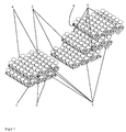
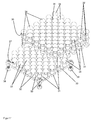
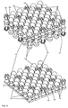
- FIGS. 1 to 7 show a first embodiment of the present invention
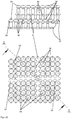
- FIG. 1 a schematic perspective view of five partially connected to each other to an open-pore body or solid plates of a bone substitute material according to the invention
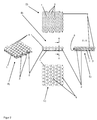
- FIG. 2 shows five schematic views of the two lower plates (base plates) after FIG. 1 , A) as a perspective view, B) as a side view, C) as a top view, D) as a view of the underside and E) as a cross-sectional view along the section AA according to FIG. 2 B)
- FIG. 3 three schematic views of three upper plates (mounting plates) after FIG. 1 , A) as a perspective view, B) as a side view and C) as a top view
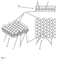
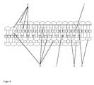
- FIG. 4 shows a schematic perspective view of three differently deeply interlocked plates of the bone substitute material according to the invention to form an open-pore volume body according to the FIGS. 1 to 3 ,
- the plates are made of an elastic biocompatible plastic or stainless steel, titanium, a titanium alloy, tantalum, a tantalum alloy can also be made of composites of these materials.
- the plates are produced using a CAM (Computer Aided Manufacturing) method or a 3D printing method, for example selective SLM (Selective Laser Melting).
- CAM Computer Aided Manufacturing
- SLM Selective Laser Melting
- Other rapid prototyping methods or computer-aided generative manufacturing methods can also be used to manufacture the plates, such as Fused Layer Modeling / Manufacturing (FLM), Fused Deposition Modeling (FDM), Laminated Object Modeling (LOM) of plastic films, Layer Laminated Manufacturing (FLM).
- FLM Fused Layer Modeling / Manufacturing
- FDM Fused Deposition Modeling
- LOM Laminated Object Modeling
- LLM low-density plastic films
- EBM electron beam melting
- MLM multi-jet modeling
- SLS selective laser sintering
- STL or SLA stereolithography
- DLP Digital Light Processing
- the plates each have a plate-shaped sheet 1, which carries the entire plates and connects to each other.
- the sheet 1 is flexible and elastically deformable, so that other surfaces can be formed as planes with the sheet 1.
- a plurality of pins 2 extend in each plate, which protrude perpendicularly from the plane of the sheet 1.
- a plurality of through recesses 3 are arranged between the pins 2, which, when the plates are connected to each other into a solid, cause an open porosity of the solid in a direction perpendicular to the sheets 1.
- FIGS. 1 to 7 For example, two different types of plates are shown, namely, base plates that have a flat underside, and in which the pins 2 extend only on one side of the sheet 1 from the sheet 1 extend, and secondly building boards, in which the pins 2 extend from both sides of the sheet 1 from.
- the base plates are in FIG. 1 below, in FIG. 2 , in FIG. 4 down and in FIG. 5 shown below.
- the mounting plates are in FIG. 1 on top, in FIG. 3 , in FIG. 4 on top, in FIG. 5 on top and the FIGS. 6 and 7 shown.
- the base plates can be attached over a large area adjacent to the bone to be treated. However, the mounting plates can also be mounted on the bone to be treated, albeit with a smaller contact surface, so that theoretically can be dispensed with the base plates.
- mushrooms 4 are provided as connecting elements 4 at the opposite ends of the sheets 1 of the pins.
- the mushrooms 4 are rounded outward (away from the sheet 1) and form spherical sections. But there are also other rounding, such as elliptical sections possible.
- the mushrooms 4 On the side facing the fabric 1, the mushrooms 4 form a flat gripping surface 6, which are suitable for hooking with other mushrooms 4 engaging plates or with the recesses 3 engaging plates.
- FIG. 5 1 shows a schematic side view of two plates of the bone substitute material according to the invention, which are hooked to one another only via the mushrooms 4,
- FIG. 6 a schematic side view of two on the mushrooms 4 and the recesses 3 of the sheet 1 with each other latched plates of the bone replacement material according to the invention and
- FIG. 7 a schematic cross-sectional view of the two on the mushrooms 4 and on the recesses 3 of the sheet 1 with each other latched plates, as in FIG. 6 shown.
- the plates are preferably adjacent to one another but not hooked or latched, so that the mushrooms 4 of the pins 2 of adjacent plates do not mesh with one another.
- the plates may be wetted with a liquid.
- the liquid preferably contains at least one pharmaceutically active substance which is suitable for controlling the infection or for stimulating bone growth.
- the plates may be coated with such a pharmaceutically active substance.
- the bone substitute material can be formed by pressing the plates into each other across their surfaces. As a result, the plates interlock or snap together and the bone substitute material is solidified in the desired shape.
- the plates can also be deformed by elastic deformation of the fabric 1 and adapted to the treatment situation. After hooking or catching with at least one other (usually then also deformed) plate, the two so interconnected plates stabilize each other, so that the selected shape is solidified.
- the plates connect to each other in such a way that free spaces between the interconnected plates in the region of the pins 2 and the mushrooms 4 remain, so that the volume formed from the plates is also porous in the directions parallel to the plane of the plates.
- the plates have a cross section or a thickness of about 5 mm, so that the remaining pores have a free cross section in the range of about 0.5 mm. This cross section is sufficient so that bone material can form or grow in the pores.
- the solid with its open pores can therefore be called osteoconductive.
- the formed from the plates volume is therefore well suited as a bone substitute material.
- the plates should be pressed tightly together so that the solid is dimensionally stable.
- the plates may in a first step get caught with each other by the mushrooms 4 elastically deforming the pins 2 of connected plates and by the elastic restoring force of the pins 2 the mushrooms 4 limit the movement of adjacent plates away from the sheet 1 (see FIG. 5 ).
- the plates can, by further pressing of the plates in a second stage with each other snap together by the mushrooms 4 are pushed through the recesses 3 of the sheet 1. This can lead to jamming of the mushrooms 4 with the recesses 3, which prevents movement of the mushrooms 4 against the adjacent plate and thus the two plates locked together.
- the edges of the mushrooms 4 plastically deform the pins 2 or the recesses 3 or the mushrooms 4 or, secondly, the edges of the recesses 3, the mushrooms 4 of adjacent plates to a small extent, thereby locking the plates together.
- Two plates can also be connected to each other by the plates are hooked together in some areas on the mushrooms 4 and in other areas on the mushrooms 4 and recesses 3 with each other be rested.
- the dimensions of the mushrooms 4, the depth of the recesses 3 (or the thickness of the sheet 1) and the length of the pins 2 between the sheet 1 and the mushrooms 4 are preferably matched to one another such that, when the plates get caught, the sheets of the sheet 1 facing away from surfaces of the mushrooms 4 on the surface of the sheet 1 of adjacent plates and rest on a rest of the plates facing away from the fabric 1 surfaces of the mushrooms 4 on the gripping surface 6 of the mushrooms 4 of the adjacent plate. This ensures that the plates are neither against each other during hooking or snapping without deformation.
- the recesses 3 each have six slots which are distributed over the circumference of the recesses 3.
- the width of the slits should be sufficient for them to be osteoconductive.
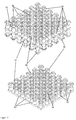
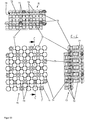
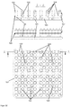
- FIG. 8 Fig. 4 shows four schematic views of interconnected plates of a second alternative bone substitute material in A) a perspective view, B) a side view, C) a top view, and D) a cross-sectional view along the section CC FIG. 8C) ,
- the plates are made of stainless steel, titanium, a titanium alloy, tantalum, a tantalum alloy but can also be made of an elastic biocompatible plastic or a composite of metallic materials.
- the plates are produced by a CAM method or a 3D printing method, for example with selective electron beam melting (EBM). Other rapid prototyping methods or computer-aided generative manufacturing methods can also be used for the production of the plates.
- the plates each have a plate-shaped sheet 11 which carries the entire plates and connects to each other.
- the sheet 11 is flexible and elastically deformable, so that other surfaces can be formed as planes with the sheet 11.
- each plate has a plurality of pins 12 extending perpendicularly from the plane of the sheets 11.
- a plurality of through recesses 13 are arranged between the pins 12, which when the plates are joined together to form a solid, an open porosity of the bulk body in a direction perpendicular to the sheets 11 can be achieved, if the adjacent plates do not abut and thereby cover the recesses 13.
- FIG. 8 only one of the two types of plates is shown, namely mounting plates, in which the pins 12 extend from both sides of the sheet 11 from. It may also be provided base plates, in which a flat bottom is provided and in which the pins 12 extend only on one side of the sheet 11 of the sheet 11 from. Such base plates can be attached over a large area adjacent to the bone to be treated. However, the mounting plates shown can also be attached to the bone to be treated, albeit with a smaller contact surface, so that can be dispensed with the base plates.
- mushrooms 14 are provided as connecting elements 14 at the flat surfaces 11 of the opposite ends of the pins 12 and in the middle between the ends of the pins 12 and the sheets 11.
- the mushrooms 14 are rounded outward (away from the sheet 11) and form spherical sections. But there are also other rounding, such as elliptical sections possible.
- the mushrooms 14 form a flat gripping surface 16 suitable for hooking with other mushrooms 14 of engaging plates or with the recesses 13 engaging plates.
- the plates abut one another but are not hooked or latched with one another (ie not as in FIG FIG. 8 shown), so that the mushrooms 14 of the pins 12 of adjacent plates do not mesh yet.
- the plates may be wetted with a liquid.
- the liquid preferably contains at least one pharmaceutically active substance which is suitable for controlling the infection or for stimulating bone growth.
- the plates may be coated with such a pharmaceutically active substance.
- the bone substitute material can be formed by pressing the plates into each other across their surfaces. As a result, the plates snag or snap together and the bone substitute material is in the desired shape solidified.
- the plates can also be deformed by elastic deformation of the fabric 11 and adapted to the treatment situation. After hooking or catching with at least one other (usually then also deformed) plate, the two plates so interconnected stabilize each other, so that the selected shape is solidified.
- the plates are mutually connected in such a way that free spaces remain between the interconnected plates in the region of the pins 12 and the mushrooms 14, so that the volume formed by the plates is open-pored in the directions parallel to the plane of the plates.
- the plates have a cross-section or a thickness of about 9 mm, so that the remaining pores have a free cross-section in the range of about 0.5 mm. This cross section is sufficient so that bone material can form or grow in the pores.
- the solid with its open pores can therefore be called osteoconductive.
- the formed from the plates volume is therefore well suited as a bone substitute material.
- the plates should be pressed tightly together so that the solid is dimensionally stable.
- the plates may catch each other in a first step as the mushrooms 14 elastically deform the pins 12 of connected plates and, by the elastic restoring force of the pins 12, the mushrooms 14 limit the movement of adjacent plates away from the sheet 11.
- the plates can snap together by pushing the outer mushrooms 14 through the recesses 13 of the sheets 11, as in FIG FIG. 8 shown. This can lead to jamming of the outer mushroom 14 with the recesses 13, which prevents movement of the mushroom 14 against the adjacent plate and thus the two plates locked together.
- the edges of the mushrooms 14 plastically deform the pins 12 or the recesses 13 or the mushrooms 14 or, secondly, the edges of the recesses 13, the mushrooms 14 of adjacent plates to a small extent and thereby latching the plates together.
- a first entanglement also takes place when the outer mushrooms 14 of adjacent plates interlock.
- Two plates can also be connected to each other by the plates are hooked together in some areas on the mushrooms 14 and locked in other areas on the mushrooms 14 and recesses 13 with each other.
- the gripping surfaces 16 or the opposite cap tops of the mushrooms 14 not completely shoot the recesses 13 and thus the recesses 13 are easily deformed by the mushrooms 14, the recesses 13 may have a plurality of slots (not shown) which distributed over the circumference of the recesses 13 are.
- the width of the slits should be sufficient for them to be osteoconductive.
- FIG. 8 So it differs from the after the FIGS. 1 to 7 especially in that the pins 12 have two mushrooms 14 spaced apart from each other. In addition, the recesses 13 have no additional slots.
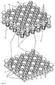
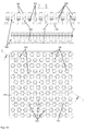
- FIG. 9 Figure 4 shows four schematic views of interconnected plates of a third alternative bone substitute material. It shows FIG. 9A) a perspective view, FIG. 9B) a side view, FIG. 9C) a top view on the top and FIG. 9D) a cross-sectional view along the section BB after FIG. 9C) ,
- the plates are made of titanium or a titanium alloy, tantalum or a tantalum alloy but can also be made of stainless steel, an elastic biocompatible plastic or a composite of such materials.
- the plates are produced by a CAM method or a 3D printing method, for example with selective electron beam melting (EBM).
- EBM selective electron beam melting
- Other rapid prototyping methods or computer-aided generative manufacturing methods can also be used for the production of the plates.
- the plates each have a plate-shaped sheet 21 which carries and connects the entire plates.
- the sheet 21 is flexible and elastically deformable, so that other surfaces than planes with the fabric 21 can be formed.
- each plate has a plurality of pins 22 extending perpendicularly from the plane of the sheets 21.
- the pins 22 there are disposed between the pins 22 a plurality of through recesses 23 which, when the plates are joined together to form a solid, can cause an open porosity of the solid in a direction perpendicular to the sheets 21, if not the adjacent sheets abut and thereby cover the recesses 23.
- FIG. 9 Only one of the two types of plates is shown, namely mounting plates, in which the pins 22 extend from both sides of the sheet 21 from.
- Base plates may also be provided in which a flat underside is provided and in which the pins 22 extend from the sheet 21 only on one side of the sheet 21.
- Such base plates can be attached over a large area adjacent to the bone to be treated.
- the mounting plates shown can also be attached to the bone to be treated, albeit with a smaller contact surface, so that can be dispensed with the base plates.
- mushrooms 24 are provided as connecting elements 24 at the opposite ends of the sheets 21 of the pins.
- the mushrooms 24 are rounded outwards (away from the sheet 21) and form spherical sections. But there are also other rounding, such as elliptical sections possible.
- the mushrooms 24 form a flat gripping surface 26 suitable for hooking or snapping with other mushrooms 24 engaging plates or plates engaging with the recesses 23.
- the plates abut one another but are not hooked or latched with one another (ie not as in FIG FIG. 9 shown), so that the mushrooms 24 of the pins 22 adjacent plates do not yet interlock.
- the plates may be wetted with a liquid.
- the liquid is preferably at least one pharmaceutically effective Contain substance that is suitable for controlling the infection or to stimulate bone growth.
- the plates may be coated with such a pharmaceutically active substance.
- the bone substitute material can be formed by pressing the plates into each other across their surfaces. As a result, the plates interlock or snap together and the bone substitute material is solidified in the desired shape.
- the plates can also be deformed by elastic deformation of the fabric 21 and adapted to the treatment situation. After hooking or catching with at least one other (usually then also deformed) plate, the two so interconnected plates stabilize each other, so that the selected shape is solidified.
- the plates connect to each other in such a way that free spaces between the interconnected plates in the region of the pins 22 and the mushrooms 24 remain, so that the volume formed from the plates is open-pored in the directions parallel to the plane of the plates.
- the plates have a cross section or a thickness of about 3 mm, so that the remaining pores have a free cross section in the range of about 0.3 mm. This cross section is sufficient so that bone material can form or grow in the pores.
- the solid with its open pores can therefore be called osteoconductive.
- the formed from the plates volume is therefore well suited as a bone substitute material.
- the plates should be pressed tightly together so that the solid is dimensionally stable.
- the plates may catch in a first step with each other by the mushrooms 24 elastically deforming the pins 22 of connected plates, and by the elastic restoring force of the pins 22 the mushrooms 24 limit the movement of adjacent plates away from the sheet 21.
- the plates can be snapped or latched by forcing the mushrooms 24 through the recesses 23 of the sheets 21, as in FIG FIG. 9 shown. This can lead to jamming of the mushrooms 24 with the recesses 23, which prevents movement of the mushrooms 24 against the adjacent plate and thus the two plates locked together.
- the edges of the mushrooms 24, the pins 22 or the recesses 23 or the mushrooms 24 or, secondly, the edges of the Recesses 23 plastically deform the mushrooms 24 adjacent plates to a small extent, thereby locking the plates together.
- Two plates can also be connected to each other by the plates are hooked together in some areas on the mushrooms 24 and locked in other areas on the mushrooms 24 and recesses 23 with each other.
- the dimensions of the mushrooms 24, the depth of the recesses 23 (or the thickness of the sheet 21) and the length of the pins 22 between the sheet 21 and the mushrooms 24 are matched to one another such that, when the sheets are joined, the sheets of the sheet 21 tillwandten surfaces of the mushrooms 24 abut against the surface of the sheet 21 of adjacent plates and / or abut the plates connecting the plates facing away from the fabric 21 surfaces of the mushrooms 24 on the gripping surface 26 of the mushrooms 24 of the adjacent plate. This ensures that the joined plates are not mutually movable without deformation.
- the gripping surfaces 26 or the opposite cap tops of the mushrooms 24 not completely shoot the recesses 23 and thus the recesses 23 are easily deformed by the mushrooms 24, the recesses 23 may have a plurality of slots (not shown), which distributed over the circumference of the recesses 23 are.
- the width of the slits should be sufficient for them to be osteoconductive.
- FIG. 9 So it differs from the after the FIGS. 1 to 7 especially in that the pins 22 and the recesses 23 have a slightly greater distance from each other. In addition, the recesses 23 have no additional slots.
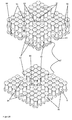
- FIG. 10 shows three schematic views of two interconnected plates of a fourth alternative bone substitute material, A) perspective view, B) top view, C) cross-sectional view along the section AA after FIG. 10B) , and the FIGS. 11 to 13 further variants of the fourth alternative bone replacement material.
- the plates are made of a biocompatible metal such as stainless steel, titanium or a titanium alloy, tantalum or a tantalum alloy but can also be made of elastic biocompatible plastic or a composite of such materials.
- the plates are with a CAM method or a 3D printing process produced, for example, with selective electron beam melting (EBM).
- EBM selective electron beam melting
- Other rapid prototyping methods or computer-aided generative manufacturing methods can also be used for the production of the plates.
- the plates each have a plate-shaped sheet 31 which carries and connects the entire plates.
- the sheet 31 is flexible and elastically deformable, so that other surfaces can be formed as planes with the sheet 31.
- each plate has a plurality of pins 32 extending perpendicularly from the plane of the sheets 31.
- In the sheet 31 there are disposed between the pins 32 a plurality of through recesses 33 which, when the plates are joined together to form a solid, can cause an open porosity of the solid in a direction perpendicular to the sheets 31, if not the adjacent plates abut and thereby cover the recesses 33.
- FIGS. 10 to 13 two different types of plates are shown, namely, base plates having a flat bottom surface and in which the pins 32 extend from the sheet 31 only on one side of the sheets 31, and secondly, mounting plates where the pins 32 are from both sides of the sheet 31 extend from.
- the base plates are in FIG. 10 below or below, in FIG. 11 below, in FIG. 12 up and in FIG. 13A) down and in FIG. 13B) to D) shown.
- the mounting plates are in FIG. 10 on top, in FIG. 11 on top, in FIG. 12 down and in FIG. 13A) shown on top of.
- the base plates can be attached over a large area adjacent to the bone to be treated. However, the mounting plates can also be mounted on the bone to be treated, albeit with a smaller contact surface, so that can be dispensed with the base plates.
- mushrooms 34 are provided as connecting elements 34 at the sheet 31 opposite ends of the pins.
- the mushrooms 34 are rounded outward (away from the sheet 31) and form ball sections. But there are also other rounding, such as elliptical sections possible.
- the Snagging or snapping with other mushrooms 34 engaging plates or with the recesses 33 engaging plates are suitable.
- the pins 32 are also provided adjacent to the gripping surfaces 36 grooves 37 as connecting elements 37, in which the mushrooms 34 adjacent plates can engage or engage.
- the grooves 37 in contrast to the grooves 37 shown, but preferred according to the invention, be formed as a negative of the shape of the curvature of the mushrooms 34 so that the mushrooms 34 fit well in the grooves 37.
- FIG. 11 shows a schematic perspective view of two interconnected via the connecting elements 34 plates of the fourth inventive bone replacement material according to the type FIG. 10 .
- FIG. 12 a schematic perspective view of two non-interconnected plates of the fourth inventive bone replacement material according to the type Figures 10 and 11 and FIG. 13 four schematic views of the fourth alternative bone substitute material in a design with defects in the pins 32
- the plates abut one another but are not hooked or latched with one another (ie not as in FIG FIG. 10A) or 11 or 13A ), so that the mushrooms 34 of the pins 32 of adjacent plates do not mesh with each other yet.
- the plates may be wetted with a liquid.
- the liquid preferably contains at least one pharmaceutically active substance which is suitable for controlling the infection or for stimulating bone growth.
- the plates may be coated with such a pharmaceutically active substance.
- the bone substitute material can be formed by pressing the plates into each other across their surfaces. As a result, the plates interlock or snap together and the bone substitute material is solidified in the desired shape. Previously, the plates can also be deformed by elastic deformation of the sheet 31 and adapted to the treatment situation.
- the two so interconnected plates stabilize each other, so that the selected shape is solidified.
- the plates are mutually connected in such a way that free spaces remain between the interconnected plates in the area of the pins 32, the mushrooms 34 and the grooves 37, so that the volume formed from the plates openly pores in the directions parallel to the plane of the plates is.
- the plates have a cross section or a thickness of about 6 mm, so that the remaining pores have a free cross section in the range of about 0.6 mm. This cross section is sufficient so that bone material can form or grow in the pores.
- the solid with its open pores can therefore be called osteoconductive.
- the formed from the plates volume is therefore well suited as a bone substitute material.
- the plates should be pressed tightly together so that the solid is dimensionally stable.
- the plates can engage in a first stage with each other by the mushrooms 34 elastically deform the pins 32 connected plates and press the mushrooms 34 or the edges of the mushrooms 34 in the grooves 37 by the elastic restoring force of the pins 32 and thereby the movement of adjacent Delimiting plates away from the sheet 31 (see Figures 10 . 11 and 13A ).
- the plates can snap together by further pressing the plates together in a second stage by pushing the mushrooms 34 through the recesses 33 of the sheets 31 (not shown). This can lead to jamming of the mushrooms 34 with the recesses 33, which prevents movement of the mushrooms 34 against the adjacent plate and thus the two plates locked together.
- the edges of the mushrooms 34 plastically deform the pins 32, the grooves 37 or the recesses 33 or the mushrooms 34 or, secondly, the edges of the recesses 33 the mushrooms 34 of adjacent plates and thereby latching the plates with each other.
- Two plates can also be connected to each other by the plates in some areas on the mushrooms 34 and grooves 37 are snapped together and locked in other areas on the mushrooms 34 and recesses 33 with each other.
- the dimensions of the mushrooms 34, the depth of the Recesses 33 (or the thickness of the sheet 31), the shape of the grooves 37 and the length of the pins 32 between the sheet 31 and the mushrooms 34 are coordinated so that when connecting the plates facing away from the fabric 31 surfaces of the mushrooms 34th abutting the surface of the sheet 31 of adjacent plates and / or in connecting the plates facing away from the fabric 31 surfaces of the mushrooms 34 on the gripping surface 36 of the mushrooms 34 and preferably along at least one line or more preferably flat on the grooves 37 of the pins 32 abut the adjacent plate. This ensures that the joined plates are not mutually movable without deformation.
- the grooves 37 also prevent the gripping surfaces 36 or the opposite cap tops of the mushrooms 34 completely covering the recesses 33.
- the recesses 33 are easily deformed by the mushrooms 34, the recesses 33 may have a plurality of slots (not shown), which are distributed over the circumference of the recesses 33.
- the width of the slits should be sufficient for them to be osteoconductive.
- the fourth embodiment according to the FIGS. 10 to 13 So it differs from the after the FIGS. 1 to 7 especially because the pins 32 are thicker and have grooves 37 as additional connecting elements. In addition, the recesses 33 have no additional slots.
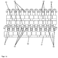
- FIG. 14 shows a schematic perspective view of two interconnected via the connecting plates plates of a fifth inventive bone substitute material.
- FIG. 15 Figure 3 shows three schematic views of the two interconnected plates of the fifth alternative bone substitute material FIG. 14 , in fact FIG. 15A) a top view, FIG. 15B) a side view and FIG. 15C) a cross-sectional view along the section BB after FIG. 15A) ,
- the plates are made of a biocompatible metal, in particular of stainless steel, titanium or a titanium alloy, tantalum or a tantalum alloy but can also be made of an elastic biocompatible plastic or a composite of such materials.
- the plates are produced by a CAM method or a 3D printing method, for example with selective electron beam melting (EBM).
- EBM selective electron beam melting
- Other rapid prototyping methods or computer-aided generative manufacturing methods can also be used for the production of the plates.
- the plates each have a plate-shaped sheet 41 which carries and connects the entire plates.
- the sheet 41 is flexible and elastically deformable, so that surfaces other than planes can be formed with the sheet 41.
- each plate has a plurality of pins 42 extending perpendicularly from the plane of the sheets 41.
- FIG. 14 and 15 two different types of plates are shown, namely, base plates that have a flat bottom surface and in which the pins 42 extend from the sheet 41 only on one side of the sheets 41, and secondly, mounting plates in which the pins 42 extend from both sides of the fabric 41 extend from.
- the base plates are in FIG. 14 below or below, in FIG. 15A) below (in the picture plane), in FIG. 15B) down and in FIG. 15C) shown on the right.
- the mounting plates are in FIG. 14 , in FIG. 15A) above (from the image plane), in FIG. 15B) up and in FIG. 15C) shown on the left.
- the base plates can be attached over a large area adjacent to the bone to be treated.
- the mounting plates can also be mounted on the bone to be treated, albeit with a smaller contact surface, so that can be dispensed with the base plates.
- mushrooms 44 or groups of four hooks 45 are provided as connecting elements 44, 45 at the flat surfaces 41 opposite ends of the pins.
- the mushrooms 44 are rounded outward (away from the sheet 41) and form ball sections. But there are also other rounding, such as elliptical sections possible.
- the hooks 45 are rounded in the same way to the outside.
- On the side facing the fabric 41 towards the mushrooms 44 form a flat gripping surface 46, which for hooking or snapping with other mushrooms 44 and hook 45th engaging plates or with the recesses 43 engaging plates are suitable.
- the hooks 45 on the side facing the fabric 41 form undercuts which are suitable for hooking or catching with other mushrooms 44 and hooks 45 of engaging plates or with the recesses 43 of engaging plates.
- the pins 42 are also provided adjacent to the gripping surfaces 46 and adjacent to the hooks 45 grooves 47 as connecting elements 47, in which the mushrooms 44 and hooks 45 adjacent plates can engage or engage.
- the grooves 47 in contrast to the grooves 47 shown, but preferred according to the invention, be formed as a negative of the shape of the curvature of the mushroom 44 and the hook 45 so that the mushrooms 44 and hooks 45 fit well into the grooves 47.
- only hooks 45 are provided as connecting elements 45 on the base plate and provided on the mounting plate exclusively mushrooms 44 as connecting elements 44. This can also be reversed and the hooks 45 and mushrooms 44 can also be mixed.
- the plates abut one another but are not hooked or latched with one another (ie not as in FIG FIG. 14 or 15 shown), so that therefore the mushrooms 44 and hooks 45 of the pins 42 of adjacent plates do not interlock yet.
- the plates may be wetted with a liquid.
- the liquid preferably contains at least one pharmaceutically active substance which is suitable for controlling the infection or for stimulating bone growth.
- the plates may be coated with such a pharmaceutically active substance.
- the bone substitute material can be formed by pressing the plates into each other across their surfaces. As a result, the plates interlock or snap together and the bone substitute material is solidified in the desired shape.
- the plates can also be deformed by elastic deformation of the fabrics 41 and adapted to the treatment situation. After hooking or catching with at least one other (usually then also deformed) plate, the two plates so interconnected stabilize each other, so that the selected shape is solidified.
- the plates connect to each other in such a way that free spaces between the interconnected plates in the region of the pins 42, the mushrooms 44, the hook 45 and the grooves 47 remain so that the volume formed from the plates in the directions parallel to Level of the plates is porous.
- the plates have a cross-section or a thickness of about 7 mm, so that the remaining pores have a free cross-section in the range of about 0.7 mm. This cross section is sufficient so that bone material can form or grow in the pores.
- the solid with its open pores can therefore be called osteoconductive.
- the formed from the plates volume is therefore well suited as a bone substitute material.
- the plates should be pressed tightly together so that the solid is dimensionally stable.
- the plates can thereby snap together in a first stage by the mushrooms 44 and hooks 45 elastically deforming the pins 42 of connected plates and by the elastic restoring force of the pins 42 the mushrooms 44 and hooks 45 and the edges of the mushrooms 44 and tips of the hooks 45 in the grooves 47 and thereby limit the movement of adjacent plates of the fabric 41 away (see Figures 14 and 15 ).
- the plates can snap together by further pushing the plates together in a second stage by pushing the mushrooms 44 and hooks 45 through the recesses 43 of the sheets 41 (not shown).
- Two plates can also be connected to each other by the plates in some areas on the mushrooms 44, hooks 45 and grooves 47 are locked together and locked in other areas on the mushrooms 44 and hooks 45 with the recesses 43.
- the dimensions of the mushrooms 44, the hook 45, the depth of the recesses 43 (or the thickness of the sheet 41), the shape of the grooves 47 and the length of the pins 42 between the fabric 41 and the mushrooms 44 or hooks 45 are matched to one another in such a way that, when the sheets are joined, the surfaces of the mushrooms 44 and hooks 45 facing away from the fabric 41 rest against the surface of the sheets 41 of adjacent sheets and / or when the sheets are joined the surfaces of the mushrooms 44 and hooks 45 facing away from the fabric 41 against the gripping surface 46 of the mushrooms 44 and preferably along at least one line or more preferably flatly against the grooves 47 of the pins 42 of the adjacent plate. This ensures that the joined plates are not mutually movable without deformation.
- the grooves 47 also prevent the gripping surfaces 46 or the opposite cap tops of the mushrooms 44 or the hooks 45 from completely covering the recesses 43.
- the recesses 43 are easily deformed by the mushrooms 44 and hook 45, the recesses 43 may have a plurality of slots (not shown), which are distributed over the circumference of the recesses 43. The width of the slits should be sufficient for them to be osteoconductive.
- the fifth embodiment according to Figures 14 and 15 So it differs from the after the FIGS. 1 to 7 especially in that the pins 42 are thicker and have grooves 47 and in that hooks 45 are provided as connecting elements 45. In addition, the recesses 43 have no additional slots.
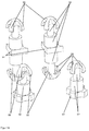
- FIG. 16 shows a schematic perspective view of two interlocked plates of a sixth inventive bone replacement material
- FIG. 17 a schematic perspective view of two non-interlocked plates of the sixth bone replacement material according to the invention
- FIG. 18 shows a schematic side view of interlocked plates of the sixth bone replacement material according to the invention FIG. 16
- FIG. 19 a schematic perspective detail view of two hooks hooked together (left) two hooks not hooked together (right) of the sixth bone replacement material according to the invention FIGS. 16 to 18 ,
- the plates consist of a biocompatible material, in particular of stainless steel, titanium or a titanium alloy, tantalum or a tantalum alloy or of an elastic biocompatible plastic. You can also choose from one Made of composite materials such.
- the plates are produced by a CAM method or a 3D printing method. The rapid prototyping methods or computer-assisted generative production methods mentioned in relation to the other exemplary embodiments can be used to produce the plates.
- the plates each have a plate-shaped sheet 51 which carries and connects the entire plates.
- the sheet 51 is flexible and elastically deformable, so that other surfaces than planes can be formed with the sheet 51.
- each plate has a plurality of pins 52 extending perpendicularly from the plane of the sheets 51.
- the pins 52 there are arranged between the pins 52 a plurality of through recesses 53 which, when the plates are joined together to form a solid, cause an open porosity of the solid in a direction perpendicular to the sheets 51.
- FIGS. 16 to 18 For example, two different types of plates are shown, namely, base plates having a flat bottom surface and with the pins 52 extending from the sheet 51 only on one side of the sheets 51, and secondly, mounting plates having the pins 52 from both sides of the sheet 51 extend from.
- the base plates are in FIG. 16 below or below, in FIG. 17 and 18 shown below.
- the mounting plates are in FIG. 16 on top and in the Figures 17 and 18 shown on top of.
- the base plates can be attached over a large area adjacent to the bone to be treated. However, the mounting plates can also be mounted on the bone to be treated, albeit with a smaller contact surface, so that can be dispensed with the base plates.
- hooks 55 are provided as connecting elements 55 at the opposite ends of the sheets 51.
- the hooks 55 are rounded outwardly (away from the sheet 51) and form parts of spherical surfaces. But there are also other rounding, such as elliptical sections possible.
- the hooks 55 form on the side facing the fabric 51 Undercuts that are suitable for hooking or snapping with other hooks 55 engaging plates or with the recesses 53 engaging plates.
- the pins 52 are formed in the area adjacent to the hooks 55 and the undercuts of the hooks 55 thinner or with a smaller cross-section. In the thinner areas, the hooks 55 adjacent plates can easily engage or snap.
- the plates abut one another but are not hooked or latched with one another (ie not as in FIG FIG. 16 or 18 shown), so that the hook 55 of the pins 52 adjacent plates do not yet interlock.
- the plates may be wetted with a liquid.
- the liquid preferably contains at least one pharmaceutically active substance which is suitable for controlling the infection or for stimulating bone growth.
- the plates may be coated with such a pharmaceutically active substance.
- the bone substitute material can be formed by pressing the plates into each other across their surfaces. As a result, the plates interlock or snap together and the bone substitute material is solidified in the desired shape.
- the plates can also be deformed by elastic deformation of the fabric 51 and adapted to the treatment situation. After hooking or catching with at least one other (usually then also deformed) plate, the two plates so interconnected stabilize each other, so that the selected shape is solidified. The hooking is in FIG. 19 shown in detail.
- the plates connect to each other in such a way that free spaces between the interconnected plates in the region of the pins 52 and the hook 55 remain so that the volume formed from the plates is open-pore in the directions parallel to the plane of the plates.
- the plates have a cross section or a thickness of about 5 mm, so that the remaining pores have a free cross section in the range of about 0.5 mm. This cross section is sufficient so that bone material can form or grow in the pores.
- the solid with its open pores can therefore be called osteoconductive.
- the formed from the plates volume is therefore well suited as a bone substitute material.
- the plates should be pressed tightly together so that the solid is dimensionally stable.
- the plates can snap together in a first stage by the hooks 55 elastically deforming the pins 52 of connected plates and pressing the hooks 55 and tips of the hooks 55 into each other by the elastic restoring force of the pins 52 and thereby the movement of adjacent plates from the sheet Limit 51 away (see Figures 16 . 18 and 19 ).
- the plates can snap together by further pressing the plates together in a second stage by pushing the hooks 55 through the recesses 53 of the sheets 51 (not shown). This can lead to a jamming of the hook 55 with the recesses 53, which prevents movement of the hook 55 against the adjacent plate and thus the two plates locked together.
- Two plates can also be interconnected by the plates are snapped together in some areas on the hooks 55 and snapped in other areas on the hooks 55 with the recesses 53.
- the dimensions of the hooks 55, the depth of the recesses 53 (or the thickness of the sheet 51) and the length of the pins 52 between the sheet 51 and the hook 55 are coordinated so that when connecting the plates of the sheet 51st facing away from the hooks 55 abut the surface of the sheet 51 of adjacent plates and / or in a connection of the plates abut the side facing away from the sheet 51 sides of the hooks 55 in the undercuts of the hook 55. This ensures that the joined plates are not mutually movable without deformation.
- the shape of the hooks 55 prevents them from completely covering the recesses 53.
- the recesses 53 are easily deformed by the hooks 55, the recesses 53 may have a plurality of slots (not shown), which are distributed over the circumference of the recesses 53.
- the sixth embodiment according to the FIGS. 16 to 19 differs from the after the FIGS. 1 to 7 above all, in that the pins 52 are thicker in regions and, in particular, in that hooks 55 are provided as connecting elements 55. In addition, the recesses 53 have no additional slots.
- FIG. 20 shows a schematic perspective view of two non-interlocked plates of a seventh bone replacement material according to the invention and FIG. 21 three schematic views of two interconnected plates of the seventh alternative bone substitute material A) as a top view, B) as a side view and C) as a cross-sectional view along the section BB after FIG. 21A) ,
- the plates are made of a biocompatible metal, in particular of stainless steel, titanium or a titanium alloy, tantalum or a tantalum alloy but can also be made of an elastic biocompatible plastic or a composite of such materials.
- the plates are produced by a CAM method or a 3D printing method, for example with selective electron beam melting (EBM).
- EBM selective electron beam melting
- Other rapid prototyping methods or computer-aided generative manufacturing methods can also be used for the production of the plates.
- the plates each have a plate-shaped sheet 61 which carries and connects the entire plates.
- the sheet 61 is flexible and elastically deformable, so that surfaces other than planes can be formed with the sheet 61.
- each plate has a plurality of pins 62 extending perpendicularly from the plane of the sheets 61.
- Disposed within the sheet 61 are a plurality of through recesses 63 between the pins 62 which, when joined together to form a solid, may cause an open porosity of the solid in a direction perpendicular to the sheets 61, if not the adjacent sheets abut and thereby cover the recesses 63.
- FIG. 20 and 21 For example, two different types of plates are shown, namely, base plates that have a flat bottom surface and in which the pins 62 extend only on one side of the sheets 61 of the sheet 61, and secondly mounting plates, in which the pins 62 extend from both sides of the sheet 61 from.
- the base plates are in FIG. 20 below, in FIG. 21A) below (in the picture plane), in FIG. 21B) down and in Figure 21C) shown on the right.
- the mounting plates are in FIG. 20 up and in FIG. 21 on top, so in FIG. 21A) above (from the image plane), in FIG. 21B) up and in Figure 21C) shown on the left.
- the base plates can be attached over a large area adjacent to the bone to be treated.
- the mounting plates can also be mounted on the bone to be treated, albeit with a smaller contact surface, so that can be dispensed with the base plates.
- mushrooms 64 or groups of four hooks 65 are provided as connecting elements 64, 65 at the opposite ends of the sheets 61 of the pins.
- the mushrooms 64 are rounded outwardly (away from the sheet 61) and form ball sections. But there are also other rounding, such as elliptical sections possible.
- the hooks 65 are rounded in the same way to the outside.
- the mushrooms 64 form a flat gripping surface 66 suitable for hooking or snapping with other mushrooms 64 and hooks 65 engaging plates or with the recesses 63 engaging plates. Accordingly, the hooks 65 on the side facing the fabric 61 undercut, which are suitable for snagging or latching with other mushrooms 64 and hooks 65 engaging plates or with the recesses 63 engaging plates.
- the pins 62 are also adjacent to the gripping surfaces 66 and adjacent to the hooks 65 grooves 67 as connecting elements 67, into which the mushrooms 64 and hooks 65 adjacent plates can engage or engage.
- the grooves 67 may be formed as a negative of the shape of the curvature of the mushrooms 64 or of the hooks 65, so that the mushrooms 64 and hooks 65 fit well into the grooves 67.
- mushrooms 64 and hooks 65 are mixedly provided on the plates as connecting members 64, 65, wherein two of eleven connecting members 64, 65 are hooks 65 and the remainder are mushrooms 64 may also be reversed and the hooks 65 and mushrooms 64 may also be in a different mixing ratio.
- the plates abut one another but are not hooked or latched with one another (ie not as in FIG FIG. 21 ), so that the mushrooms 64 and hooks 65 of the pins 62 of adjacent plates do not mesh with each other yet.
- the plates may be wetted with a liquid.
- the liquid preferably contains at least one pharmaceutically active substance which is suitable for controlling the infection or for stimulating bone growth.
- the plates may be coated with such a pharmaceutically active substance.
- the bone substitute material can be formed by pressing the plates into each other across their surfaces. As a result, the plates interlock or snap together and the bone substitute material is solidified in the desired shape.
- the plates can also be deformed by elastic deformation of the fabric 61 and adapted to the treatment situation. After hooking or catching with at least one other (usually then also deformed) plate, the two so interconnected plates stabilize each other, so that the selected shape is solidified.
- the plates are mutually connected in such a way that free spaces remain between the interconnected plates in the area of the pins 62, the mushrooms 64, the hooks 65 and the grooves 67, so that the formed of the plates volume body in the directions parallel to Level of the plates is porous.
- the plates have a cross section or thickness of about 9 mm, so that the remaining pores have a free cross section in the range of about 0.9 mm. This cross section is sufficient so that bone material can form or grow in the pores.
- the solid with its open pores can therefore be called osteoconductive.
- the formed from the plates volume is therefore well suited as a bone substitute material.
- the plates should be pressed tightly together so that the solid is dimensionally stable.
- the plates can in a first step with each other by the mushrooms 64 and hooks 65 elastically deform the pins 62 connected plates and by the elastic restoring force of the pins 62, the mushrooms 64 and Hook 65 or the edges of the mushrooms 64 and tips of the hooks 65 press into the grooves 67 and thereby limit the movement of adjacent plates away from the sheet 61 (see FIG. 21 ).
- the plates can snap together by further pressing the plates together in a second stage by pushing the mushrooms 64 and hooks 65 through the recesses 63 of the sheets 61 (not shown).
- Two plates can be further interconnected by the plates in some areas on the mushrooms 64, hook 65 and grooves 67 are locked together and locked in other areas on the mushrooms 64 and / or hooks 65 with the recesses 63.
- the dimensions of the mushrooms 64, the hook 65, the depth of the recesses 63 (or the thickness of the sheet 61), the shape of the grooves 67, and the length of the pins 62 between the sheet 61 and the mushrooms 64 or hooks 65 are so superimposed that the surfaces of the mushrooms 64 and hooks 65 facing away from the fabric 61 abut against the surface of the sheets 61 of adjacent plates and / or when connecting the plates, the surfaces of the mushrooms 64 and hooks facing away from the fabric 61 65 on the gripping surface 66 of the mushrooms 64 and preferably along at least one line or more preferably lie flat against the grooves 67 of the pins 62 of the adjacent plate. This ensures that the joined plates are not mutually movable without deformation.
- the grooves 67 also prevent the gripping surfaces 66 or the opposite cap tops of the mushrooms 64 or hooks 65 from completely covering the recesses 63.
- the recesses 63 are easily deformed by the mushrooms 64 and hooks 65, the recesses 63 may have a plurality of slots (not shown), which are distributed over the circumference of the recesses 63.
- the width of the slits should be sufficient for them to be osteoconductive.
- the fifth embodiment according to Figures 20 and 21 So it differs from the after the FIGS. 1 to 7 especially in that the pins 62 are thicker and have grooves 67 and in that hooks 65 are provided as connecting elements 65. In addition, the recesses 63 have no additional slots.
- FIG. 22 shows a schematic perspective view of two non-interlocked plates of an eighth bone replacement material according to the invention and FIG. 23 three schematic views of two interconnected plates of the eighth alternative bone substitute material, FIG. 23A) a top view, FIG. 23B) a side view and FIG. 23C) a cross-sectional view along the section CC after FIG. 23A) ,
- FIG. 24 shows a schematic perspective view of two non-interlocked plates of a modification of the eighth bone replacement material according to the invention and FIG. 25 three schematic views of two interconnected plates of the modification of the eighth alternative bone substitute material, FIG. 25A) a top view, FIG. 25B) a side view and FIG. 25C) a cross-sectional view along the section CC after FIG. 23A) ,
- the plates are made of a titanium or a titanium alloy, tantalum or a tantalum alloy can also be made of another elastic biocompatible material.
- the plates are produced by a CAM method or a 3D printing method, for example with selective electron beam melting (EBM). Other rapid prototyping methods or computer-aided generative manufacturing methods can also be used for the production of the plates.
- the plates each have a plate-shaped sheet 71 which carries and connects the entire plates.
- the sheet 71 is flexible and elastically deformable, so that other surfaces than planes can be formed with the sheet 71.
- each plate has a plurality of pins 72 extending perpendicularly from the plane of the sheets 71.
- a plurality of through recesses 73 are arranged between the pins 72, which, when the plates are connected together to form a solid, an open Porosity of the volume body in a direction perpendicular to the sheets 71 can cause, if not abut the adjacent plates and thereby cover the recesses 73.
- FIGS. 22 to 25 For example, two different types of plates are shown, namely, base plates having a flat bottom surface and with the pins 72 extending from the sheet 71 on only one side of the sheets 71, and secondly, mounting plates having the pins 72 from both sides of the sheet 71 extend from.
- the base plates are in FIG. 22 below, in FIG. 23A) below (in the picture plane), in FIG. 23B) down and in FIG. 23C) shown on the right as well as in FIG. 24 below, in FIG. 25A) below (in the picture plane), in FIG. 25B) down and in FIG. 25C) shown on the right.
- the mounting plates are in FIG. 22 and 24 up and in FIG. 23 on top, so in FIG.
- the base plates can be attached over a large area adjacent to the bone to be treated.
- the mounting plates can also be mounted on the bone to be treated, albeit with a smaller contact surface, so that can be dispensed with the base plates.
- mushrooms 74 or groups of four hooks 75 are provided as connecting elements 74, 75 at the opposite ends of the sheets 71 of the pins.
- the mushrooms 74 are rounded outwards (away from the sheet 71) and form spherical sections. But there are also other rounding, such as elliptical sections possible.
- the hooks 75 are rounded in the same way to the outside.
- the mushrooms 74 On the side facing the sheet 71, the mushrooms 74 have undercuts 76 which are suitable for hooking or snapping with hooks 75 of engaging plates.
- the hooks 75 on the side facing the sheet 71 form undercuts which are suitable for hooking or latching with other mushrooms 74 and hooks 75 of engaging plates or with the recesses 73 of engaging plates.
- pins 72 are also provided adjacent to the undercuts 76 and adjacent to the hooks 75 grooves 77 as connecting elements 77, in which engage and engage the mushrooms 74 and hooks 75 adjacent plates can.
- the edges 71 of the grooves 77 facing the sheet 71 are formed rounded, so that the mushrooms 74 and hooks 75 fit well into the grooves 77 or slide.
- mushrooms 74 and hooks 75 are mixedly provided on the plates as connecting members 74, 75.
- the variant of the Figures 22 and 23 are two of eleven fasteners 74, 75 hooks 75 and the rest mushrooms 74.
- Eight of eleven fasteners 74, 75 are hooks 75 and the remainder are mushrooms 74. This may be the other way around, and hooks 75 and mushrooms 74 may also be in a different mix ratio.
- the plates abut each other but not hooked together or latched (ie not as in the FIG. 23 and 25 ), so that the mushrooms 74 and hooks 75 of the pins 72 of adjacent plates do not mesh with each other yet.
- the plates may be wetted with a liquid.
- the liquid preferably contains at least one pharmaceutically active substance which is suitable for controlling the infection or for stimulating bone growth.
- the plates may be coated with such a pharmaceutically active substance.
- the bone substitute material can be formed by pressing the plates into each other across their surfaces. As a result, the plates interlock or snap together and the bone substitute material is solidified in the desired shape.
- the plates can also be deformed by elastic deformation of the fabric 71 and adapted to the treatment situation. After hooking or catching with at least one other (usually then also deformed) plate, the two so interconnected plates stabilize each other, so that the selected shape is solidified.
- the plates connect to each other in such a way that free spaces between the interconnected plates in the region of the pins 72, the mushroom 74, the hook 75 and the grooves 77 remain so that the volume formed from the plates in the directions parallel to Level of the plates is porous.
- the plates have a cross section or a thickness between 5 mm and 10 mm, so that the remaining pores have a free cross section in the area between about 0.5 mm and 1 mm. This cross section is sufficient so that bone material can form or grow in the pores.
- the solid with its open pores can therefore be called osteoconductive.
- the formed from the plates volume is therefore well suited as a bone substitute material.
- the plates should be pressed tightly together so that the solid is dimensionally stable.
- the plates can thereby snap together in a first stage by the mushrooms 74 and hooks 75 elastically deforming the pins 72 of connected plates and by the elastic restoring force of the pins 72 the mushrooms 74 and hooks 75 or the edges of the mushrooms 74 and tips of the hooks 75 in the grooves 77 and thereby limit the movement of adjacent plates away from the sheet 71 (see Figures 23 and 25 ).
- the plates can snap together by further interlocking of the plates in a second stage by pushing the mushrooms 74 and hooks 75 through the recesses 73 of the sheets 71 (not shown).
- Two plates can be further interconnected by the plates in some areas on the mushrooms 74, hook 75 and grooves 77 are locked together and locked in other areas on the mushrooms 74 and / or hook 75 with the recesses 73.
- the dimensions of the mushrooms 74, the hook 75, the depth of the recesses 73 (or the thickness of the sheet 71), the shape of the grooves 77, and the length of the pins 72 between the sheet 71 and the mushrooms 74 or hooks 75 are so superimposed that the surfaces of the mushrooms 74 and hooks 75 facing away from the fabric 71 abut against the surface of the sheets 71 of adjacent sheets and / or when joining the sheets, the surfaces of the mushrooms 74 and 74 facing away from the fabric 71 Hook 75 in the undercuts 76 of the mushrooms 74 and preferably along at least one line to the grooves 77 of the pins 72 of the adjacent plate. This ensures that the joined plates are not mutually movable without deformation.
- the grooves 77 also prevent the gripping surfaces 76 or the opposing cap tops of the mushrooms 74 or the hooks 75 from completely covering the recesses 73.
- the recesses 73 may have a plurality of slots (not shown) distributed about the circumference of the recesses 73. The width of the slits should be sufficient for them to be osteoconductive.
- the eighth embodiment according to FIGS. 22 to 25 So it differs from the after the Figures 20 and 21 in that the mushrooms 74 have undercuts 76 in which the hooks 75 of adjacent plates can engage.
- FIG. 26 shows a schematic perspective view of three and six pairs of interconnected plates of the eighth alternative bone substitute material and three particles of a bone substitute material, wherein the plates can be connected to the particles.
- the particles are composed of a core located in the geometric center of the particle and twenty pins 82 extending radially away from the core in different directions.
- At the ends of the pins 82 are either mushrooms 84 or a group of four hooks 85 as connecting elements 84, 85 arranged on the otherwise cylindrical pins 82.
- the mushrooms 84 and hooks 85 correspond to the mushrooms 74 and hooks 75 of the plates and are similarly sized.
- the mushrooms 84 and the hooks 85 are accordingly spherically rounded outwardly (away from the core). There are also other rounding, such as elliptical sections possible.
- the mushrooms At the core-oriented side, the mushrooms have 84 undercuts. Likewise, the hooks 85 have undercuts.
- the undercuts of the mushrooms 84 and undercuts of the hooks 85 are suitable for hooking and / or snapping with other mushrooms 84 and hooks 85 of engaging particles or for snagging and / or snapping with the mushrooms 74 and hooks 75 engaging plates.
- the pins 72 and connecting elements 74, 75 of the plates are matched to the pins 82 and connecting elements 84, 85 of the particles, so that a uniform stability can be achieved.
- the materials from which the particles are made may be the same as those of the plates, and the same manufacturing methods may be used.
- the plates may be connected to the bone of a patient via fasteners (not shown) in the form of points or screws. Subsequently, further plates of the bone substitute material according to the invention or the particles can be attached to the plates.
- the particles and the plates combine with each other in such a way that free spaces remain between the interconnected particles and plates, so that the voluminous body formed and solidified from the particles and plates is open-pore.
- the free cross-sections of the open-pore structure must still be sufficient so that bone material can form or grow in the pores.
- the body formed by the plates and particles with its open pores can therefore be called osteoconductive.
- the surface of the particles may also be coated with a substance that promotes bone growth. The formed from the particles and plates solid is therefore well suited as a bone substitute material.
- FIGS. 27 to 30 show plates of a ninth alternative bone replacement material according to the invention, which is particularly preferred according to the invention. It shows FIG. 27 a schematic perspective view of two plates latched together, FIG. 28 a schematic perspective view of the two non-latched plates after FIG. 27 .
- FIG. 29 two schematic views of the two interlocked plates after FIG. 27 in a top view ( FIG. 29 below) and in a side view ( FIG. 29 above) and FIG. 30 a schematic cross-sectional view of the section AA according to FIG. 29 below the plates latched to each other after the Figures 27 and 29 ,
- the plates are made of a titanium or a titanium alloy, tantalum or a tantalum alloy can also be made of another elastic biocompatible material.
- the plates are produced by a CAM method or a 3D printing method, for example with selective electron beam melting (EBM). Other rapid prototyping methods or computer-aided generative manufacturing methods can also be used for the production of the plates.
- the plates each have a plate-shaped sheet 91 which carries and connects the entire plates.
- the sheet 91 is flexible and elastically deformable, so that other surfaces than planes can be formed with the sheet 91.
- each plate has a plurality of pins 92 extending perpendicularly from the plane of the sheets 91.
- FIGS. 27 to 30 For example, two different types of plates are shown, namely, base plates having a flat bottom surface and with the pins 92 extending from the sheet 91 on only one side of the sheets 91, and secondly, mounting plates having the pins 92 from both sides of the sheet 91 extend from.
- the base plates are in FIG. 27 below or below, in FIG. 28 and in the side view FIG. 29 below, in the supervision after FIG. 29 below (in the picture plane) and in FIG. 30 shown lower left.
- the mounting plates are in FIG. 27 on top, in FIG. 28 and in the side view FIG. 29 above, in the supervision to FIG. 29 above (from the picture plane) and in FIG. 30 shown on the top right.
- the base plates can be attached over a large area adjacent to the bone to be treated. However, the mounting plates can also be mounted on the bone to be treated, albeit with a smaller contact surface, so that can be dispensed with the base plates.
- mushrooms 94 are provided as connecting elements 94 at the sheet 91 opposite ends of the pins.
- the mushrooms 94 are rounded outwards (away from the sheet 91) and form spherical sections. But there are also other rounding, such as elliptical sections possible.
- the mushrooms 94 form a flat gripping surface 96 suitable for hooking or snapping with other mushrooms 94 of engaging plates or with the recesses 93 of engaging plates.
- the pins 92 are also provided adjacent to the mushrooms 94 and the gripping surfaces 96 grooves 97 as connecting elements 97, in which the mushrooms 94 adjacent plates can engage or engage.
- the edges 91 of the grooves 97 facing the fabric 91 are formed rounded so that the mushrooms 94 fit well into the grooves 97 or slide.
- the shape of the grooves 97 corresponds to a negative of the shape of the surface of the mushrooms 94, so that they can rest along a line in one of the grooves 97.
- the mushrooms 94 thus form locking means 94 and the grooves 97 the matching counter-locking means 97. Further insertion of the plate is prevented by this structure.
- the pins 92 with the mushrooms 94 are arranged in groups or islands of respectively sixteen pins 92 and mushrooms 94.
- the pins 92 arranged at the edge of the groups or islands can bend more easily outwards when the mushrooms 94 of another plate are pressed open.
- the plates are easier to connect to one another, since the elastic deformations of the pins 92 do not interfere with one another when the mushrooms 94 snap into the grooves 97.
- mushrooms 94 and grooves 97 are provided as connecting members 94, 97 on the plates.
- hooks could also be provided as connecting elements on the pins 92.
- the plates abut each other but not hooked together or latched (ie not as in the FIG. 27 . 29 and 30 shown), so that the mushrooms 94 of the pins 92 of adjacent plates do not mesh yet.
- the plates may be wetted with a liquid.
- the liquid preferably contains at least one pharmaceutically active substance which is suitable for controlling the infection or for stimulating bone growth.
- the plates may be coated with such a pharmaceutically active substance.
- the bone substitute material can be formed by pressing the plates into each other across their surfaces. As a result, the plates interlock or snap together and the bone substitute material is solidified in the desired shape.
- the plates can also by elastic deformation of the Fabrics 91 deformed and adapted to the treatment situation. After hooking or catching with at least one other (usually then also deformed) plate, the two plates so interconnected stabilize each other, so that the selected shape is solidified.
- the plates are mutually connected in such a way that free spaces remain between the interconnected plates in the region of the pins 92, the mushrooms 94 and the grooves 97, so that the volume formed from the plates openly pores in the directions parallel to the plane of the plates is.
- the plates have a cross section or a thickness between 5 mm and 10 mm, so that the remaining pores have a free cross section in the range between about 0.5 mm and 1 mm. This cross section is sufficient so that bone material can form or grow in the pores.
- the solid with its open pores can therefore be called osteoconductive.
- the formed from the plates volume is therefore well suited as a bone substitute material.
- the plates should be pressed tightly together so that the solid is dimensionally stable.
- the plates may snap together as the mushrooms 94 elastically deform the pins 92 of connected plates and, by the resilient restoring force of the pins 92, press the mushrooms 94 or the edges of the mushrooms 94 into the grooves 97, thereby moving adjacent plates from the sheet Limit 91 away (see Figures 27 . 29 and 30 ).
- By the adapted shape of the grooves 97 to the mushrooms 94 further movement of the mushrooms 94 is blocked, especially when a large number of mushrooms 94 is engaged in a large number of grooves 97.
- the dimensions of the mushrooms 94, the thickness of the sheet 91, the shape of the grooves 97 and the length of the pins 92 between the sheet 91 and the mushrooms 94 are coordinated so that when connecting the plates the surfaces facing away from the sheet 91 surfaces the mushrooms 94 and hooks 95 abut the surface of the grooves 97 of adjacent plates and / or, when the plates are joined, the gripping surfaces 96 of the mushrooms 94 abut the gripping surfaces 96 of the mushrooms 94 of the adjacent plate. This ensures that the joined plates are not movable against each other without great force.
- the grooves 97 also prevent the gripping surfaces 96 or the opposite cap tops of the mushrooms 94 completely covering the recesses 93.
- the recesses 93 may have a plurality of slots (not shown) which are distributed over the circumference of the recesses 93.
- the ninth embodiment according to the FIGS. 27 to 30 So it differs from the after the FIGS. 1 to 7 primarily because the mushrooms 94 have matching grooves 97 as additional connecting elements into which the mushrooms 94 of adjacent plates can snap, and in that the pins 92 are thicker. In addition, the recesses 93 have no additional slots.
- FIG. 31 shows a schematic perspective view of a plurality of plates of a tenth and eleventh bone replacement material according to the invention, which are partially interlocked via their connecting elements 104, 114 with each other.
- FIG. 33 and 36 show plates of a tenth alternative bone replacement material according to the invention, which is particularly preferred according to the invention. It shows FIG. 33 three schematic views of a plate of the tenth alternative bone substitute material, and that FIG. 33 Below a top view, FIG. 33 Middle a side view and FIG. 33 Above a cross-sectional view along the section BB after FIG. 33 Below.
- FIG. 36 shows two schematic views of two interconnected plates of the tenth alternative bone substitute material in FIG. 36 Below is a top view on the top and FIG. 36 Above a cross-sectional view along the section EE after FIG. 36 Below.
- FIG. 34 and 37 show plates of an eleventh alternative bone replacement material according to the invention, which is particularly preferred according to the invention. It shows FIG. 34 three schematic views of a plate of the tenth alternative bone substitute material, and that FIG. 34 Below a top view, FIG. 34 Middle a side view and FIG. 34 Above a cross-sectional view along the section CC after FIG. 34 Below.
- FIG. 37 shows two schematic views of two interconnected plates of the eleventh alternative bone substitute material in FIG. 37 Below is a top view on the top and FIG. 37 Above a cross-sectional view along the section FF to FIG. 37 Below.
- FIG. 32 and 35 show plates of a twelfth alternative bone replacement material according to the invention, which is also particularly preferred according to the invention. It shows FIG. 32 three schematic views of a plate of the twelfth alternative bone substitute material, and that FIG. 32 Below a top view, FIG. 32 Middle a side view and FIG. 32 Above a cross-sectional view along the section AA after FIG. 32 Below.
- FIG. 35 shows two schematic views of two interconnected plates of the tenth alternative bone substitute material in FIG. 35 Below is a top view on the top and FIG. 35 Above a cross-sectional view along the section DD after FIG. 35 Below.
- the plates are made of a titanium or a titanium alloy, tantalum or a tantalum alloy can also be made of another elastic biocompatible material.
- the plates are produced by a CAM method or a 3D printing method, for example with selective electron beam melting (EBM). Other rapid prototyping methods or computer-aided generative manufacturing methods can also be used for the production of the plates.
- the plates each have a plate-shaped sheet 101, 111, 121 which carries and connects the entire plates.
- the fabric 101, 111, 121 is flexible and elastically deformable, so that other surfaces than planes with the fabric 101, 111, 121 can be formed.
- each plate has a plurality of pins 102, 112, 122 projecting perpendicularly from the plane of the sheets 101, 111, 121.
- a plurality of through recesses 103, 113, 123 are arranged between the pins 102, 112, 122, which, when the plates are joined together to form a solid, have an open porosity of the solid in a direction perpendicular can cause to the sheets 101, 111, 121, if not abut the adjacent plates and thereby the recesses 103, 113, 123 cover.
- FIGS. 31 to 37 For example, in the tenth, eleventh, and twelfth embodiments, two different types of disks are shown, namely, first Base plates having a flat bottom surface and in which the pins 102, 112, 122 extend from the sheet 101, 111, 121 on only one side of the sheets 101, 111, 121, and secondly, mounting plates in which the pins 102 , 112, 122 extend from both sides of the sheet 101, 111, 121.
- the base plates are in FIG. 31 bottom left, in the Figures 32 . 33 and 34 as well as in the Figures 35 . 36 and 37 each shown as the lower of the two plates.
- the mounting plates are in FIG. 31 right above and in the Figures 35 . 36 .
- the base plates can be attached over a large area adjacent to the bone to be treated.
- the mounting plates can also be mounted on the bone to be treated, albeit with a smaller contact surface, so that can be dispensed with the base plates.
- the mushrooms 104, 124 form ball portions at the tips of the pins 102, 122, whereas in the eleventh embodiment, the mushrooms 114 are made slightly sharper at the tips of the pins 112. But there are also other rounding, such as elliptical sections possible.
- the mushrooms 104, 114, 124 which are arranged below the mushrooms 104, 114, 124 at the tip of the pins 102, 112, 122, that is, on the pins 102, 112, 122 between the sheet 101, 111, 121 and the mushrooms 104, 114, 124 which are arranged on the side facing away from the sheet 101, 111, 121 side of the pins 102, 112, 122, have the shape of a truncated cone or are blunt-conical.
- the mushrooms 104, 114, 124 form a flat gripping surface 106, 116, 126, which engage with other mushrooms 104, 114, 124 engaging plates or with the recesses 103, 113, 123 of engaging plates are suitable.
- the pins 112 and mushrooms 114 of the eleventh embodiment ( Figures 31 . 34 and 37 ) have a slightly smaller diameter than those of the tenth and twelfth embodiments, with the gripping surfaces 116 of the eleventh embodiment being slightly deeper or larger than the gripping surfaces 106, 126 of the tenth and twelfth embodiments.
- the pins 102, 112, 122 are also adjacent to the mushrooms 104, 114, 124 and the gripping surfaces 106, 116, 126 grooves 107, 117, 127 provided as connecting elements 107, 117, 127, in which the mushrooms 104, 114, 124 adjacent plates can engage or engage.
- the shape of the grooves 107, 117, 127 corresponds approximately to a negative of the shape of the surface of the mushrooms 104, 114, 124, so that they can rest along a line in one of the grooves 107, 117, 127.
- the mushrooms 104, 114, 124 thus form latching means 104, 114, 124 and the grooves 107, 117, 127 the matching counter-latching means 107, 117, 127. Further insertion of the plates is in the tenth, eleventh and twelfth embodiment possible by the pins 102, 112, 122 with the mushrooms 104, 114, 124 are pressed into or through the recesses 103, 113, 123.
- the pins 122 with the mushrooms 124 are arranged in groups of islands of forty-six pins 122, respectively.
- the pins 122 arranged at the edge of the groups or islands can more easily bend outwardly when the mushrooms 124 of another plate are pressed open.
- the plates are easier to connect to each other, since the elastic deformations of the pins 122 do not interfere with each other when engaging the mushrooms 124 in the grooves 127.
- the plates abut one another but are not hooked or latched with one another, so that the mushrooms 104, 114, 124 of the pins 102, 112, 122 of adjacent plates do not mesh with one another.
- the plates may be wetted with a liquid.
- the liquid preferably contains at least one pharmaceutically active substance which is suitable for controlling the infection or for stimulating bone growth.
- the plates may be coated with such a pharmaceutically active substance.
- the bone substitute material can be formed by pressing the plates into each other across their surfaces. As a result, the plates interlock or snap together and the bone substitute material is solidified in the desired shape.
- the plates can also by elastic deformation of the Fabrics 101, 111, 121 deformed and adapted to the treatment situation. After hooking or catching with at least one other (usually then also deformed) plate, the two plates so interconnected stabilize each other, so that the selected shape is solidified.
- the plates connect to each other in such a way that free spaces between the interconnected plates in the region of the pins 102, 112, 122, the mushrooms 104, 114, 124 and the grooves 107, 117, 127 remain, so that from the Plate shaped volume body is open-pored in the directions parallel to the plane of the plates.
- the plates have a cross section or a thickness between 5 mm and 10 mm, so that the remaining pores have a free cross section in the range between about 0.5 mm and 1 mm. This cross section is sufficient so that bone material can form or grow in the pores.
- the solid with its open pores can therefore be called osteoconductive.
- the formed from the plates volume is therefore well suited as a bone substitute material.
- the pins 102, 112, 122 are thinnest between the mushrooms 104, 114, 124 and the sheets 101, 111, 121, so that the pins 102, 112, 122 are the lightest in the area of connection to the sheets 101, 111, 121 can be bent, or there are the most mobile to the locking process or the hooking of the mushrooms 104, 114, 124 with the grooves 107, 117, 127 between the mushrooms 104, 114, 124 to allow.
- the plates should be pressed tightly together so that the solid is dimensionally stable.
- the plates can thereby hook in a first step by the mushrooms 104, 114, 124 elastically deforming the pins 102, 112, 122 of connected plates and by the elastic restoring force of the pins 102, 112, 122 the mushrooms 104, 114, 124 or the edges of the mushrooms 104, 114, 124 press into the grooves 107, 117, 127 and thereby limit the movement of adjacent plates of the sheet 101, 111, 121 away (see FIGS. 35 to 37 ).
- the plates can snap together by further pressing of the plates in a second step by pushing the mushrooms 104, 114, 124 through the recesses 103, 113, 123 of the sheets 101, 111, 121 (not shown). This can lead to a jamming of the mushrooms 104, 114, 124 with the recesses 103, 113, 123, the movement of the mushrooms 104, 114, 124 prevented against the adjacent plate and thus the two plates locked together.
- a first entanglement also takes place already when the outer mushrooms 104, 114, 124 mesh with one another at the tips of the pins 102, 112, 122 of adjacent plates.
- Two plates can also be connected to each other by the plates are hooked together in some areas on the mushrooms 104, 114, 124 and locked in other areas on the mushrooms 104, 114, 124 and recesses 103, 113, 123 with each other.
- the dimensions of the mushrooms 104, 114, 124, the depth of the recesses 103, 113, 123 (or the thickness of the sheets 101, 111, 121) and the length of the pins 102, 112, 122 between the sheet 101, 111, are preferred.
- the tenth, eleventh and twelfth embodiment of the FIGS. 31 to 37 So it differs from the after the FIGS. 1 to 7 above all, that by the plurality of superposed mushrooms 104, 114, 124 they can interlock with each other in different positions, so that a bone substitute material made therefrom can be formed particularly accurately and with slight variations in thickness.
- more and more mushrooms 104, 114, 124 engage in the grooves 107, 117, 127 of adjacent plates, so that an increasingly stable bond is created.
Landscapes
- Health & Medical Sciences (AREA)
- Orthopedic Medicine & Surgery (AREA)
- Life Sciences & Earth Sciences (AREA)
- Engineering & Computer Science (AREA)
- Veterinary Medicine (AREA)
- Public Health (AREA)
- General Health & Medical Sciences (AREA)
- Animal Behavior & Ethology (AREA)
- Oral & Maxillofacial Surgery (AREA)
- Heart & Thoracic Surgery (AREA)
- Vascular Medicine (AREA)
- Biomedical Technology (AREA)
- Transplantation (AREA)
- Cardiology (AREA)
- Chemical Kinetics & Catalysis (AREA)
- Chemical & Material Sciences (AREA)
- Physical Education & Sports Medicine (AREA)
- General Chemical & Material Sciences (AREA)
- Bioinformatics & Cheminformatics (AREA)
- Medicinal Chemistry (AREA)
- Nuclear Medicine, Radiotherapy & Molecular Imaging (AREA)
- Organic Chemistry (AREA)
- Pharmacology & Pharmacy (AREA)
- Prostheses (AREA)
- Materials For Medical Uses (AREA)
Applications Claiming Priority (1)
| Application Number | Priority Date | Filing Date | Title |
|---|---|---|---|
| DE102015107599.7A DE102015107599A1 (de) | 2015-05-13 | 2015-05-13 | Flächiges Knochenersatzmaterial und Verfahren zur Herstellung eines porösen Körpers |
Publications (2)
| Publication Number | Publication Date |
|---|---|
| EP3092977A1 true EP3092977A1 (fr) | 2016-11-16 |
| EP3092977B1 EP3092977B1 (fr) | 2019-09-11 |
Family
ID=55913469
Family Applications (1)
| Application Number | Title | Priority Date | Filing Date |
|---|---|---|---|
| EP16167165.6A Active EP3092977B1 (fr) | 2015-05-13 | 2016-04-26 | Materiau plat de remplacement osseux et procede de production d'un corps poreux |
Country Status (7)
| Country | Link |
|---|---|
| US (1) | US9861483B2 (fr) |
| EP (1) | EP3092977B1 (fr) |
| JP (1) | JP6224766B2 (fr) |
| CN (1) | CN106137463B (fr) |
| AU (1) | AU2016202848B2 (fr) |
| CA (1) | CA2928066C (fr) |
| DE (1) | DE102015107599A1 (fr) |
Families Citing this family (4)
| Publication number | Priority date | Publication date | Assignee | Title |
|---|---|---|---|---|
| US11666446B2 (en) * | 2017-07-21 | 2023-06-06 | Warsaw Orthopedic, Inc. | Bone implant for enclosing bone material |
| TWI715969B (zh) * | 2019-04-23 | 2021-01-11 | 歐耿良 | 組合式補骨片及補骨片單元 |
| CN111281611B (zh) * | 2019-12-30 | 2022-05-24 | 雅博尼西医疗科技(苏州)有限公司 | 多孔性结构和基底的连接方法 |
| CN111166532B (zh) * | 2019-12-30 | 2022-03-01 | 武汉联影智融医疗科技有限公司 | 人工关节及其制备方法 |
Citations (15)
| Publication number | Priority date | Publication date | Assignee | Title |
|---|---|---|---|---|
| CH295638A (fr) | 1951-10-22 | 1954-01-15 | Velcro Sa Soulie | Dispositif d'accrochage. |
| DE1625396A1 (de) | 1966-07-07 | 1970-06-25 | Minnesota Mining & Mfg | Befestigungsmittel |
| DE1610318A1 (de) | 1966-01-04 | 1970-10-22 | American Velco Inc | Trennbarer Verschluss |
| US4290174A (en) | 1976-08-13 | 1981-09-22 | Minnesota Mining And Manufacturing Company | Separable fastener and article for making same |
| US5077870A (en) | 1990-09-21 | 1992-01-07 | Minnesota Mining And Manufacturing Company | Mushroom-type hook strip for a mechanical fastener |
| US20030055511A1 (en) * | 2000-03-03 | 2003-03-20 | Schryver Jeffrey E. | Shaped particle comprised of bone material and method of making the particle |
| DE102004048464A1 (de) | 2004-10-05 | 2006-04-13 | Reinz-Dichtungs-Gmbh | Halterungsvorrichtung |
| DE102006015100A1 (de) | 2006-03-31 | 2007-10-11 | Reinz-Dichtungs-Gmbh | Halterungsvorrichtung |
| DE102006015148A1 (de) | 2006-03-31 | 2007-10-11 | Reinz-Dichtungs-Gmbh | Halterungsvorrichtung |
| DE102006015145A1 (de) | 2006-03-31 | 2007-10-11 | Reinz-Dichtungs-Gmbh | Halterungsvorrichtung |
| WO2013074909A1 (fr) | 2011-11-18 | 2013-05-23 | Zimmer, Inc. | Dispositif métallique poreux pour régénérer une interface tissu mou-os |
| FR2990860A1 (fr) * | 2012-05-23 | 2013-11-29 | 3Dceram | Structure ceramique poreuse |
| WO2014006519A1 (fr) * | 2012-07-04 | 2014-01-09 | Celoplas - Plásticos Para A Industria S.A. | Produit multicouche moulé poreux en trois dimensions et son procédé de production |
| EP2832320A1 (fr) * | 2013-07-30 | 2015-02-04 | Aesculap Ag | Implant osseux ayant des points d'insertion |
| DE102015110202B3 (de) * | 2015-06-25 | 2016-06-09 | Heraeus Medical Gmbh | Bausatz zum Aufbau eines Käfigs für die Spondylodese und Verfahren hierzu sowie entsprechender Käfig und dessen Verwendung |
Family Cites Families (9)
| Publication number | Priority date | Publication date | Assignee | Title |
|---|---|---|---|---|
| DE19543530C1 (de) * | 1995-11-22 | 1997-05-07 | Eska Implants Gmbh & Co | Implantat als Knochenersatz |
| US6251143B1 (en) * | 1999-06-04 | 2001-06-26 | Depuy Orthopaedics, Inc. | Cartilage repair unit |
| DE10006822A1 (de) * | 2000-02-08 | 2001-08-23 | Michael Sittinger | Künstliche Knochenchips, Verfahren zu ihrer Herstellung und ihre Verwendung |
| WO2001066044A2 (fr) * | 2000-03-03 | 2001-09-13 | Smith & Nephew, Inc. | Particule façonnee et composition pour carence osseuse, et procede de fabrication de ladite particule |
| US6974480B2 (en) * | 2001-05-03 | 2005-12-13 | Synthes (Usa) | Intervertebral implant for transforaminal posterior lumbar interbody fusion procedure |
| CA2533534C (fr) * | 2003-07-24 | 2013-03-19 | Tecomet, Inc. | Mousses non aleatoires assemblees |
| US20070179607A1 (en) * | 2006-01-31 | 2007-08-02 | Zimmer Technology, Inc. | Cartilage resurfacing implant |
| DE102013004574A1 (de) * | 2013-03-11 | 2014-09-11 | Johnson & Johnson Medical Gmbh | Chirurgisches Implantat |
| DE102013014295A1 (de) * | 2013-08-22 | 2015-02-26 | Johnson & Johnson Medical Gmbh | Chirurgisches Implantat |
-
2015
- 2015-05-13 DE DE102015107599.7A patent/DE102015107599A1/de active Pending
-
2016
- 2016-04-25 CA CA2928066A patent/CA2928066C/fr not_active Expired - Fee Related
- 2016-04-26 EP EP16167165.6A patent/EP3092977B1/fr active Active
- 2016-05-02 US US15/144,192 patent/US9861483B2/en active Active
- 2016-05-04 AU AU2016202848A patent/AU2016202848B2/en not_active Ceased
- 2016-05-09 JP JP2016093864A patent/JP6224766B2/ja not_active Expired - Fee Related
- 2016-05-13 CN CN201610319108.6A patent/CN106137463B/zh not_active Expired - Fee Related
Patent Citations (15)
| Publication number | Priority date | Publication date | Assignee | Title |
|---|---|---|---|---|
| CH295638A (fr) | 1951-10-22 | 1954-01-15 | Velcro Sa Soulie | Dispositif d'accrochage. |
| DE1610318A1 (de) | 1966-01-04 | 1970-10-22 | American Velco Inc | Trennbarer Verschluss |
| DE1625396A1 (de) | 1966-07-07 | 1970-06-25 | Minnesota Mining & Mfg | Befestigungsmittel |
| US4290174A (en) | 1976-08-13 | 1981-09-22 | Minnesota Mining And Manufacturing Company | Separable fastener and article for making same |
| US5077870A (en) | 1990-09-21 | 1992-01-07 | Minnesota Mining And Manufacturing Company | Mushroom-type hook strip for a mechanical fastener |
| US20030055511A1 (en) * | 2000-03-03 | 2003-03-20 | Schryver Jeffrey E. | Shaped particle comprised of bone material and method of making the particle |
| DE102004048464A1 (de) | 2004-10-05 | 2006-04-13 | Reinz-Dichtungs-Gmbh | Halterungsvorrichtung |
| DE102006015100A1 (de) | 2006-03-31 | 2007-10-11 | Reinz-Dichtungs-Gmbh | Halterungsvorrichtung |
| DE102006015148A1 (de) | 2006-03-31 | 2007-10-11 | Reinz-Dichtungs-Gmbh | Halterungsvorrichtung |
| DE102006015145A1 (de) | 2006-03-31 | 2007-10-11 | Reinz-Dichtungs-Gmbh | Halterungsvorrichtung |
| WO2013074909A1 (fr) | 2011-11-18 | 2013-05-23 | Zimmer, Inc. | Dispositif métallique poreux pour régénérer une interface tissu mou-os |
| FR2990860A1 (fr) * | 2012-05-23 | 2013-11-29 | 3Dceram | Structure ceramique poreuse |
| WO2014006519A1 (fr) * | 2012-07-04 | 2014-01-09 | Celoplas - Plásticos Para A Industria S.A. | Produit multicouche moulé poreux en trois dimensions et son procédé de production |
| EP2832320A1 (fr) * | 2013-07-30 | 2015-02-04 | Aesculap Ag | Implant osseux ayant des points d'insertion |
| DE102015110202B3 (de) * | 2015-06-25 | 2016-06-09 | Heraeus Medical Gmbh | Bausatz zum Aufbau eines Käfigs für die Spondylodese und Verfahren hierzu sowie entsprechender Käfig und dessen Verwendung |
Non-Patent Citations (1)
| Title |
|---|
| J. M. RUEGER: "Knochenersatzmittel", ORTHOPÄDE, vol. 27, 1998, pages 72 - 79 |
Also Published As
| Publication number | Publication date |
|---|---|
| CN106137463A (zh) | 2016-11-23 |
| US9861483B2 (en) | 2018-01-09 |
| EP3092977B1 (fr) | 2019-09-11 |
| AU2016202848B2 (en) | 2017-05-18 |
| DE102015107599A1 (de) | 2016-11-17 |
| JP6224766B2 (ja) | 2017-11-01 |
| CN106137463B (zh) | 2019-07-09 |
| AU2016202848A1 (en) | 2016-12-01 |
| CA2928066C (fr) | 2018-09-11 |
| JP2016209591A (ja) | 2016-12-15 |
| US20160331540A1 (en) | 2016-11-17 |
| CA2928066A1 (fr) | 2016-11-13 |
Similar Documents
| Publication | Publication Date | Title |
|---|---|---|
| DE102015110202B3 (de) | Bausatz zum Aufbau eines Käfigs für die Spondylodese und Verfahren hierzu sowie entsprechender Käfig und dessen Verwendung | |
| DE102015107600B4 (de) | Partikuläres alloplastisches Knochenersatzmaterial und Verfahren zur Herstellung eines frei geformten porösen Körpers | |
| EP3389567B1 (fr) | Produits medicaux et kit médical pour utilisation dans le traitement, en particulier pour une utilisation lors de remplissage et / ou de clôture, une cavité osseuse | |
| EP0245846B1 (fr) | Dispositif prothétique et son procédé de fabrication | |
| DE4208247C1 (de) | Implantat als Knochenersatz | |
| DE102009014184A1 (de) | Implantat zur Fusion von Wirbelsäulensegmenten | |
| EP3092977B1 (fr) | Materiau plat de remplacement osseux et procede de production d'un corps poreux | |
| EP2526900B1 (fr) | Moule destiné à la fabrication d'un composant de fémur d'un espaceur d'articulation du genou | |
| DE2824118A1 (de) | Dentales implantat | |
| DE9190095U1 (de) | Poröse Fixierungsfläche | |
| DE9490333U1 (de) | Gegossene Knocheneinwachsoberfläche | |
| DE2502884A1 (de) | Mittel zur biologischen implantation von knochen- und gelenkersatz | |
| EP3651686B1 (fr) | Implant osseux destiné à être utilisé comme pièce de remplissage lors de la correction d'une malposition d'un os dans le domaine de la dysgnathie et procédé pour sa fabrication | |
| DE10120330A1 (de) | Verfahrensweise zur Herstellung von Implantatgußmodellen aus Modulen als Oberflächenelemente mit einer makroporöser Implantatoberfläche mit interkonnektierenden Räumen | |
| WO2008061759A1 (fr) | Pièce constituée d'éléments de treillis | |
| DE102011050183A1 (de) | Oberflächenprofilierter Gitterkörper | |
| EP0554301B1 (fr) | Implant et son procede de fabrication | |
| EP2832320B1 (fr) | Implant osseux ayant des points d'insertion | |
| DE202011050057U1 (de) | Oberflächenprofilierter Gitterkörper | |
| EP4197494B1 (fr) | Dispositif d'augmentation, composite et procédé de fabrication d'un composite | |
| DE2905647A1 (de) | Als knochenimplantat ausgebildetes verankerungselement | |
| DE4227002A1 (de) | Hüftgelenkpfanne zur Implantation in einer Knochenausnehmung | |
| EP3946165A1 (fr) | Implant en un matériau de support entrecoupé de matériau donneur biologiquement actif et procédé de sa fabrication | |
| EP4294468B1 (fr) | Implant pour implantation dans un organisme et procedure | |
| EP4691424A1 (fr) | Implant pour remplacer ou remplir un défaut d'un os de type feuille et procédé de fabrication d'un tel implant |
Legal Events
| Date | Code | Title | Description |
|---|---|---|---|
| PUAI | Public reference made under article 153(3) epc to a published international application that has entered the european phase |
Free format text: ORIGINAL CODE: 0009012 |
|
| 17P | Request for examination filed |
Effective date: 20160426 |
|
| AK | Designated contracting states |
Kind code of ref document: A1 Designated state(s): AL AT BE BG CH CY CZ DE DK EE ES FI FR GB GR HR HU IE IS IT LI LT LU LV MC MK MT NL NO PL PT RO RS SE SI SK SM TR |
|
| AX | Request for extension of the european patent |
Extension state: BA ME |
|
| STAA | Information on the status of an ep patent application or granted ep patent |
Free format text: STATUS: EXAMINATION IS IN PROGRESS |
|
| 17Q | First examination report despatched |
Effective date: 20181128 |
|
| GRAP | Despatch of communication of intention to grant a patent |
Free format text: ORIGINAL CODE: EPIDOSNIGR1 |
|
| STAA | Information on the status of an ep patent application or granted ep patent |
Free format text: STATUS: GRANT OF PATENT IS INTENDED |
|
| RIC1 | Information provided on ipc code assigned before grant |
Ipc: A61F 2/30 20060101ALN20190509BHEP Ipc: A61F 2/28 20060101AFI20190509BHEP |
|
| INTG | Intention to grant announced |
Effective date: 20190607 |
|
| GRAS | Grant fee paid |
Free format text: ORIGINAL CODE: EPIDOSNIGR3 |
|
| GRAA | (expected) grant |
Free format text: ORIGINAL CODE: 0009210 |
|
| STAA | Information on the status of an ep patent application or granted ep patent |
Free format text: STATUS: THE PATENT HAS BEEN GRANTED |
|
| AK | Designated contracting states |
Kind code of ref document: B1 Designated state(s): AL AT BE BG CH CY CZ DE DK EE ES FI FR GB GR HR HU IE IS IT LI LT LU LV MC MK MT NL NO PL PT RO RS SE SI SK SM TR |
|
| REG | Reference to a national code |
Ref country code: GB Ref legal event code: FG4D Free format text: NOT ENGLISH |
|
| REG | Reference to a national code |
Ref country code: CH Ref legal event code: EP |
|
| REG | Reference to a national code |
Ref country code: AT Ref legal event code: REF Ref document number: 1177509 Country of ref document: AT Kind code of ref document: T Effective date: 20190915 |
|
| REG | Reference to a national code |
Ref country code: DE Ref legal event code: R096 Ref document number: 502016006513 Country of ref document: DE Ref country code: IE Ref legal event code: FG4D Free format text: LANGUAGE OF EP DOCUMENT: GERMAN |
|
| REG | Reference to a national code |
Ref country code: NL Ref legal event code: MP Effective date: 20190911 |
|
| REG | Reference to a national code |
Ref country code: LT Ref legal event code: MG4D |
|
| PG25 | Lapsed in a contracting state [announced via postgrant information from national office to epo] |
Ref country code: NO Free format text: LAPSE BECAUSE OF FAILURE TO SUBMIT A TRANSLATION OF THE DESCRIPTION OR TO PAY THE FEE WITHIN THE PRESCRIBED TIME-LIMIT Effective date: 20191211 Ref country code: BG Free format text: LAPSE BECAUSE OF FAILURE TO SUBMIT A TRANSLATION OF THE DESCRIPTION OR TO PAY THE FEE WITHIN THE PRESCRIBED TIME-LIMIT Effective date: 20191211 Ref country code: SE Free format text: LAPSE BECAUSE OF FAILURE TO SUBMIT A TRANSLATION OF THE DESCRIPTION OR TO PAY THE FEE WITHIN THE PRESCRIBED TIME-LIMIT Effective date: 20190911 Ref country code: HR Free format text: LAPSE BECAUSE OF FAILURE TO SUBMIT A TRANSLATION OF THE DESCRIPTION OR TO PAY THE FEE WITHIN THE PRESCRIBED TIME-LIMIT Effective date: 20190911 Ref country code: LT Free format text: LAPSE BECAUSE OF FAILURE TO SUBMIT A TRANSLATION OF THE DESCRIPTION OR TO PAY THE FEE WITHIN THE PRESCRIBED TIME-LIMIT Effective date: 20190911 Ref country code: FI Free format text: LAPSE BECAUSE OF FAILURE TO SUBMIT A TRANSLATION OF THE DESCRIPTION OR TO PAY THE FEE WITHIN THE PRESCRIBED TIME-LIMIT Effective date: 20190911 |
|
| PG25 | Lapsed in a contracting state [announced via postgrant information from national office to epo] |
Ref country code: ES Free format text: LAPSE BECAUSE OF FAILURE TO SUBMIT A TRANSLATION OF THE DESCRIPTION OR TO PAY THE FEE WITHIN THE PRESCRIBED TIME-LIMIT Effective date: 20190911 Ref country code: AL Free format text: LAPSE BECAUSE OF FAILURE TO SUBMIT A TRANSLATION OF THE DESCRIPTION OR TO PAY THE FEE WITHIN THE PRESCRIBED TIME-LIMIT Effective date: 20190911 Ref country code: GR Free format text: LAPSE BECAUSE OF FAILURE TO SUBMIT A TRANSLATION OF THE DESCRIPTION OR TO PAY THE FEE WITHIN THE PRESCRIBED TIME-LIMIT Effective date: 20191212 Ref country code: RS Free format text: LAPSE BECAUSE OF FAILURE TO SUBMIT A TRANSLATION OF THE DESCRIPTION OR TO PAY THE FEE WITHIN THE PRESCRIBED TIME-LIMIT Effective date: 20190911 Ref country code: LV Free format text: LAPSE BECAUSE OF FAILURE TO SUBMIT A TRANSLATION OF THE DESCRIPTION OR TO PAY THE FEE WITHIN THE PRESCRIBED TIME-LIMIT Effective date: 20190911 |
|
| PG25 | Lapsed in a contracting state [announced via postgrant information from national office to epo] |
Ref country code: PT Free format text: LAPSE BECAUSE OF FAILURE TO SUBMIT A TRANSLATION OF THE DESCRIPTION OR TO PAY THE FEE WITHIN THE PRESCRIBED TIME-LIMIT Effective date: 20200113 Ref country code: RO Free format text: LAPSE BECAUSE OF FAILURE TO SUBMIT A TRANSLATION OF THE DESCRIPTION OR TO PAY THE FEE WITHIN THE PRESCRIBED TIME-LIMIT Effective date: 20190911 Ref country code: IT Free format text: LAPSE BECAUSE OF FAILURE TO SUBMIT A TRANSLATION OF THE DESCRIPTION OR TO PAY THE FEE WITHIN THE PRESCRIBED TIME-LIMIT Effective date: 20190911 Ref country code: EE Free format text: LAPSE BECAUSE OF FAILURE TO SUBMIT A TRANSLATION OF THE DESCRIPTION OR TO PAY THE FEE WITHIN THE PRESCRIBED TIME-LIMIT Effective date: 20190911 Ref country code: PL Free format text: LAPSE BECAUSE OF FAILURE TO SUBMIT A TRANSLATION OF THE DESCRIPTION OR TO PAY THE FEE WITHIN THE PRESCRIBED TIME-LIMIT Effective date: 20190911 Ref country code: NL Free format text: LAPSE BECAUSE OF FAILURE TO SUBMIT A TRANSLATION OF THE DESCRIPTION OR TO PAY THE FEE WITHIN THE PRESCRIBED TIME-LIMIT Effective date: 20190911 |
|
| PG25 | Lapsed in a contracting state [announced via postgrant information from national office to epo] |
Ref country code: IS Free format text: LAPSE BECAUSE OF FAILURE TO SUBMIT A TRANSLATION OF THE DESCRIPTION OR TO PAY THE FEE WITHIN THE PRESCRIBED TIME-LIMIT Effective date: 20200224 Ref country code: SK Free format text: LAPSE BECAUSE OF FAILURE TO SUBMIT A TRANSLATION OF THE DESCRIPTION OR TO PAY THE FEE WITHIN THE PRESCRIBED TIME-LIMIT Effective date: 20190911 Ref country code: SM Free format text: LAPSE BECAUSE OF FAILURE TO SUBMIT A TRANSLATION OF THE DESCRIPTION OR TO PAY THE FEE WITHIN THE PRESCRIBED TIME-LIMIT Effective date: 20190911 Ref country code: CZ Free format text: LAPSE BECAUSE OF FAILURE TO SUBMIT A TRANSLATION OF THE DESCRIPTION OR TO PAY THE FEE WITHIN THE PRESCRIBED TIME-LIMIT Effective date: 20190911 |
|
| REG | Reference to a national code |
Ref country code: DE Ref legal event code: R097 Ref document number: 502016006513 Country of ref document: DE |
|
| PLBE | No opposition filed within time limit |
Free format text: ORIGINAL CODE: 0009261 |
|
| STAA | Information on the status of an ep patent application or granted ep patent |
Free format text: STATUS: NO OPPOSITION FILED WITHIN TIME LIMIT |
|
| PG2D | Information on lapse in contracting state deleted |
Ref country code: IS |
|
| PG25 | Lapsed in a contracting state [announced via postgrant information from national office to epo] |
Ref country code: DK Free format text: LAPSE BECAUSE OF FAILURE TO SUBMIT A TRANSLATION OF THE DESCRIPTION OR TO PAY THE FEE WITHIN THE PRESCRIBED TIME-LIMIT Effective date: 20190911 Ref country code: IS Free format text: LAPSE BECAUSE OF FAILURE TO SUBMIT A TRANSLATION OF THE DESCRIPTION OR TO PAY THE FEE WITHIN THE PRESCRIBED TIME-LIMIT Effective date: 20200112 |
|
| 26N | No opposition filed |
Effective date: 20200615 |
|
| PG25 | Lapsed in a contracting state [announced via postgrant information from national office to epo] |
Ref country code: SI Free format text: LAPSE BECAUSE OF FAILURE TO SUBMIT A TRANSLATION OF THE DESCRIPTION OR TO PAY THE FEE WITHIN THE PRESCRIBED TIME-LIMIT Effective date: 20190911 |
|
| PG25 | Lapsed in a contracting state [announced via postgrant information from national office to epo] |
Ref country code: MC Free format text: LAPSE BECAUSE OF FAILURE TO SUBMIT A TRANSLATION OF THE DESCRIPTION OR TO PAY THE FEE WITHIN THE PRESCRIBED TIME-LIMIT Effective date: 20190911 |
|
| REG | Reference to a national code |
Ref country code: CH Ref legal event code: PL |
|
| PG25 | Lapsed in a contracting state [announced via postgrant information from national office to epo] |
Ref country code: LI Free format text: LAPSE BECAUSE OF NON-PAYMENT OF DUE FEES Effective date: 20200430 Ref country code: CH Free format text: LAPSE BECAUSE OF NON-PAYMENT OF DUE FEES Effective date: 20200430 Ref country code: LU Free format text: LAPSE BECAUSE OF NON-PAYMENT OF DUE FEES Effective date: 20200426 |
|
| REG | Reference to a national code |
Ref country code: BE Ref legal event code: MM Effective date: 20200430 |
|
| PG25 | Lapsed in a contracting state [announced via postgrant information from national office to epo] |
Ref country code: BE Free format text: LAPSE BECAUSE OF NON-PAYMENT OF DUE FEES Effective date: 20200430 |
|
| PG25 | Lapsed in a contracting state [announced via postgrant information from national office to epo] |
Ref country code: IE Free format text: LAPSE BECAUSE OF NON-PAYMENT OF DUE FEES Effective date: 20200426 |
|
| PG25 | Lapsed in a contracting state [announced via postgrant information from national office to epo] |
Ref country code: TR Free format text: LAPSE BECAUSE OF FAILURE TO SUBMIT A TRANSLATION OF THE DESCRIPTION OR TO PAY THE FEE WITHIN THE PRESCRIBED TIME-LIMIT Effective date: 20190911 Ref country code: MT Free format text: LAPSE BECAUSE OF FAILURE TO SUBMIT A TRANSLATION OF THE DESCRIPTION OR TO PAY THE FEE WITHIN THE PRESCRIBED TIME-LIMIT Effective date: 20190911 Ref country code: CY Free format text: LAPSE BECAUSE OF FAILURE TO SUBMIT A TRANSLATION OF THE DESCRIPTION OR TO PAY THE FEE WITHIN THE PRESCRIBED TIME-LIMIT Effective date: 20190911 |
|
| REG | Reference to a national code |
Ref country code: AT Ref legal event code: MM01 Ref document number: 1177509 Country of ref document: AT Kind code of ref document: T Effective date: 20210426 |
|
| PG25 | Lapsed in a contracting state [announced via postgrant information from national office to epo] |
Ref country code: MK Free format text: LAPSE BECAUSE OF FAILURE TO SUBMIT A TRANSLATION OF THE DESCRIPTION OR TO PAY THE FEE WITHIN THE PRESCRIBED TIME-LIMIT Effective date: 20190911 |
|
| PG25 | Lapsed in a contracting state [announced via postgrant information from national office to epo] |
Ref country code: AT Free format text: LAPSE BECAUSE OF NON-PAYMENT OF DUE FEES Effective date: 20210426 |
|
| P01 | Opt-out of the competence of the unified patent court (upc) registered |
Effective date: 20230527 |
|
| PGFP | Annual fee paid to national office [announced via postgrant information from national office to epo] |
Ref country code: FR Payment date: 20230424 Year of fee payment: 8 |
|
| PGFP | Annual fee paid to national office [announced via postgrant information from national office to epo] |
Ref country code: GB Payment date: 20230419 Year of fee payment: 8 |
|
| GBPC | Gb: european patent ceased through non-payment of renewal fee |
Effective date: 20240426 |
|
| PG25 | Lapsed in a contracting state [announced via postgrant information from national office to epo] |
Ref country code: GB Free format text: LAPSE BECAUSE OF NON-PAYMENT OF DUE FEES Effective date: 20240426 |
|
| PG25 | Lapsed in a contracting state [announced via postgrant information from national office to epo] |
Ref country code: FR Free format text: LAPSE BECAUSE OF NON-PAYMENT OF DUE FEES Effective date: 20240430 |
|
| PG25 | Lapsed in a contracting state [announced via postgrant information from national office to epo] |
Ref country code: GB Free format text: LAPSE BECAUSE OF NON-PAYMENT OF DUE FEES Effective date: 20240426 Ref country code: FR Free format text: LAPSE BECAUSE OF NON-PAYMENT OF DUE FEES Effective date: 20240430 |
|
| PGFP | Annual fee paid to national office [announced via postgrant information from national office to epo] |
Ref country code: DE Payment date: 20250422 Year of fee payment: 10 |