EP3092986A2 - Dispositif ophtalmologique a vide et interface patient - Google Patents
Dispositif ophtalmologique a vide et interface patient Download PDFInfo
- Publication number
- EP3092986A2 EP3092986A2 EP16168672.0A EP16168672A EP3092986A2 EP 3092986 A2 EP3092986 A2 EP 3092986A2 EP 16168672 A EP16168672 A EP 16168672A EP 3092986 A2 EP3092986 A2 EP 3092986A2
- Authority
- EP
- European Patent Office
- Prior art keywords
- vacuum
- interface
- pressure sensor
- patient
- pressure
- Prior art date
- Legal status (The legal status is an assumption and is not a legal conclusion. Google has not performed a legal analysis and makes no representation as to the accuracy of the status listed.)
- Granted
Links
Images


Classifications
-
- A—HUMAN NECESSITIES
- A61—MEDICAL OR VETERINARY SCIENCE; HYGIENE
- A61B—DIAGNOSIS; SURGERY; IDENTIFICATION
- A61B3/00—Apparatus for testing the eyes; Instruments for examining the eyes
- A61B3/10—Objective types, i.e. instruments for examining the eyes independent of the patients' perceptions or reactions
- A61B3/14—Arrangements specially adapted for eye photography
- A61B3/15—Arrangements specially adapted for eye photography with means for aligning, spacing or blocking spurious reflection ; with means for relaxing
- A61B3/152—Arrangements specially adapted for eye photography with means for aligning, spacing or blocking spurious reflection ; with means for relaxing for aligning
-
- A—HUMAN NECESSITIES
- A61—MEDICAL OR VETERINARY SCIENCE; HYGIENE
- A61F—FILTERS IMPLANTABLE INTO BLOOD VESSELS; PROSTHESES; DEVICES PROVIDING PATENCY TO, OR PREVENTING COLLAPSING OF, TUBULAR STRUCTURES OF THE BODY, e.g. STENTS; ORTHOPAEDIC, NURSING OR CONTRACEPTIVE DEVICES; FOMENTATION; TREATMENT OR PROTECTION OF EYES OR EARS; BANDAGES, DRESSINGS OR ABSORBENT PADS; FIRST-AID KITS
- A61F9/00—Methods or devices for treatment of the eyes; Devices for putting in contact-lenses; Devices to correct squinting; Apparatus to guide the blind; Protective devices for the eyes, carried on the body or in the hand
- A61F9/007—Methods or devices for eye surgery
- A61F9/008—Methods or devices for eye surgery using laser
- A61F9/009—Auxiliary devices making contact with the eyeball and coupling in laser light, e.g. goniolenses
Definitions
- the present invention relates to devices and methods in the field of ophthalmology.
- the invention relates to vacuum devices for coupling a patient interface to a patient's eye as well as patient interfaces.
- the invention further relates to methods for coupling a patient interface to a patient's eye.
- Corresponding devices such as ophthalmic laser devices have, for example, a base unit with a laser light source for generating laser pulses, for example femtosecond laser pulses, and an application head with a projection objective, which is coupled to the patient's eye for treatment.
- the application head can be movably connected to the base unit, for example via an articulated arm, wherein the articulated arm can at the same time serve as the optical beam guide from the laser light source to the application head.
- a corresponding arrangement is for example in the EP 1731120 disclosed.
- the application head is integrated in the base unit or in which other device arrangements are provided.
- the mechanical and optical coupling of the application head to the patient's eye takes place via a patient interface, wherein the patient interface can comprise a transparent contact body, through which the laser pulses emerging from the projection objective guided by mechanical contact with the cornea with respect to the patient interface and the projection lens fixed.
- a fluid coupling can be provided, wherein a coupling fluid, for example physiological saline solution, is located between the cornea and the projection objective.
- Corresponding patient interfaces are for example from WO 2012031277 known.
- the coupling of the patient interface to the patient's eye can take place by means of a vacuum and a vacuum cavity of the patient interface.
- the vacuum cavity is typically a suction ring placed on the cornea.
- Most suction rings have two sealing lips. The lips may be attached to the sclera, the sclera and the cornea or only on the cornea. Furthermore, there are variants that have only one ring and create a vacuum over the entire eye, or variants that consist of several suction chambers / suction cups.
- the suction ring is the most common method of attachment, but there are other known solutions.
- the coupling to the patient's eye by a vacuum or a negative pressure in a vacuum cavity of the patient interface the vacuum cavity along its circumference sealingly rests on the patient's eye and the patient interface coupled so fluidly sealing to the patient's eye and seals against the environment.
- the generation of the negative pressure can be effected by a vacuum generator, in particular a vacuum pump or vacuum pump.
- the coupling of the patient interface to the application head is carried out in known systems, for example by means of screw, bayonet or vacuum couplings.
- the US 2002/0120285 A1 discloses a blade guide for an ophthalmic surgical instrument which is vacuum-fixed on the patient's eye and measures the contact pressure between the sclera and the blade guide.
- the US 2002/0198553 A1 discloses a patented interface and a fluid pressure sensing vacuum device wherein the connection to the patient interface is via a common fluidic conduit.
- the WO 2008/150330 discloses a patient interface which is provided for coupling by vacuum to the patient's eye and constructed in two parts, wherein contact pressure sensors are arranged at a coupling point between the parts, which detect a contact load between the parts.
- Such a situation may occur, for example, when the line connecting the vacuum cavity of the patient interface with the vacuum generator is blocked.
- This can be z. B. arise because the directed out of the vacuum cavity air flow in the construction of the negative pressure liquid, for example used in cataract surgery Viscoelastika, or Sterilabdeckfolie or connective tissue, and so serving for suction vacuum connection line itself and / or its Anschuss and the vacuum cavity, z. B. the interior of the suction ring, completely or partially blocked.
- the negative pressure generator in the vacuum cavity of the patient interface can not build up or maintain sufficient negative pressure for secure fixation.
- Another typical source of error is the generation of temporary or permanent leakage between the vacuum cavity and the patient's eye or within the fluidic system, such as the vacuum connection line itself or its fittings.
- This object is achieved in a general form by the subject matter of the independent claims. Exemplary or advantageous embodiments are defined by the dependent claims as well as the overall disclosure of the present document.
- the object is achieved by providing a vacuum device for fixing a patient interface on a patient's eye.
- the vacuum device comprises a vacuum generator and a device-side vacuum interface for fluidically coupling the vacuum generator to a vacuum cavity of the patient interface.
- the vacuum cavity is typically formed by the interior of a suction ring.
- the fixation of the patient interface on the patient's eye means in the narrower sense the fixation of a patient interface body on the patient's eye, for example on the cornea and / or sclera.
- a side of the patient interface body opposite the patient's eye is designed for coupling an ophthalmological application head.
- the patient interface as a whole may include other components such as, in particular, connection leads.
- the vacuum device further comprises a fluidic pressure sensor and a device-side pressure sensor interface for the vacuum interface functionally separate coupling of the pressure sensor to the patient interface. Since pressure and force are well known over the surface, the pressure sensor can technically also be designed as a force sensor. The term “pressure sensor” is thus also to be read as a “pressure-sensitive sensor” or “pressure-sensitive sensor”.
- the pressure sensor as typically electrical pressure sensor basically known type can be combined with other components of the vacuum device and z. B. may be arranged in a common housing.
- the device side pressure sensor interface is a fluidic interface.
- the pressure sensor may be spatially separate from other components of the vacuum device, in particular separately from the vacuum generator and / or the control device.
- the pressure sensor z. B. arranged directly on the attached to the patient's eye patient interface body or be part of a patient interface body.
- the device-side sensor interface z. B. be an electrical or fiber optic interface.
- the vacuum device from a single compact device or consist of a number of separate devices or devices with appropriate operational coupling.
- the coupling of the pressure sensor to the patient interface z. B. such that the pressure sensor is subjected to the negative pressure in the interior of the vacuum cavity and this measures.
- the pressure sensor instead of a fluidic pressure sensor, the pressure sensor may be a contact pressure sensor and arranged to be acted upon and to measure the contact pressure between the patient interface, in particular the patient interface body, and the patient's eye , In any case, during operation, the pressure sensor measures a pressure or a force that is functionally related to the inter-pressure in the interior of the vacuum cavity.
- the vacuum device further comprises a control unit operatively coupled to the vacuum generator and the pressure sensor or the device side pressure sensor interface, the control unit being configured to drive the vacuum generator to generate a negative pressure in the vacuum cavity.
- the control unit is further designed to evaluate a pressure determined by the pressure sensor.
- the evaluation of the pressure can include or consist of determining a faulty fluidic coupling of the vacuum volume.
- the faulty fluidic coupling can be a faulty fluidic coupling to the patient's eye and / or a faulty fluidic coupling to the vacuum device or its vacuum generator.
- a faulty fluidic coupling of the vacuum cavity to the vacuum generator and / or the patient's eye can in particular result from leakage / leakage and / or due to a pseudo-vacuum as previously described during the aspiration of the air from the pressurized volume or during ongoing operation.
- the faulty fluidic coupling has the consequence that the required negative pressure in the vacuum cavity is at least partially lost or can not be built up correctly.
- Fluid coupling in the context of the present document preferably means a geometrically defined fluidic coupling, for example by means of geometrically defined flow channels such as hoses, tubes and / or connecting pieces, and not a geometrically undefined fluidic coupling via the surrounding atmosphere.
- “Functionally separate coupling” means that the coupling is independent of the rest of the fluidic system and there are no or only negligible fluidic interactions. As shown in more detail below, this results in particular by means of a connection via separate flow channels, such as a separate fluidic connection line and / or a direct integration of the pressure sensor in the patient interface body. The only fluidic coupling between pressure sensor interface and vacuum interface and thus between the pressure sensor and the vacuum generator thus takes place via the vacuum cavity of the patient interface.
- a functionally separate coupling thus requires a fluidically separate coupling.
- a functionally separate coupling of the pressure sensor to the vacuum cavity means in particular that there is no fluidic connection between the pressure sensor and the device-side pressure sensor interface on the one hand and other fluidic components of the vacuum device on the other hand, in particular the device-side vacuum interface and the vacuum generator.
- the functionally separate or functionally independent coupling extends to the entire fluidic path between the pressure sensor and the vacuum cavity.
- the flow channel connecting the pressure sensor to the vacuum cavity thus leads fluidically independently and preferably without branches from the pressure sensor to the vacuum cavity and opens directly into the vacuum cavity.
- the vacuum generator typically comprises a vacuum pump basically known Beauart, but may additionally or alternatively include other vacuum or suction devices, in particular a vacuum reservoir in the form of a vacuum-loaded container.
- the vacuum device further comprises fluidic components such as one or more valves which may be wholly or partially operatively coupled to and controlled by the control unit, and throttles and pressure relief valves.
- the control unit is implemented as an electronic circuit in a basically known manner and typically includes one or more microprocessors and / or microcontrollers, memory components, other analog and / or digital semiconductor components, etc.
- Methods and algorithms for controlling the vacuum generator and for the evaluation and processing of the pressure sensor signal are typically implemented in whole or in part in the form of program code for the at least one microprocessor and / or microcontroller, but can also be wholly or partially realized by appropriate circuit components.
- the patient interface can be designed for coupling to the patient's eye by means of coupling fluid and / or for applanating coupling by means of a transparent contact body.
- the desired negative pressure p nom required for secure fixation of the patient interface and to be produced and maintained by the negative pressure device is in a typical range of, for example, -200 mbar ... 850 mbar, with a higher negative pressure being typically selected for coupling an applanating patient interface than for a patient interface with fluid coupling.
- Negative pressures in this document refer to negative pressures relative to atmospheric pressure.
- the control unit and the vacuum generator are typically designed to control pressure fluctuations and to maintain the desired vacuum.
- the coupling of the patient interface with a therapy or diagnostic device for example a laser application head, can take place before or after the coupling with the patient's eye.
- the vacuum interface and the pressure sensor interface are typically designed as functionally detachable and non-destructive fluidic couplers, such as fluidic connectors.
- the coupling of the patient interface with a therapy or diagnostic device can take place before or after the coupling with the patient's eye.
- the device-side pressure sensor interface can also be a data interface, for example an electrical or optical Interface, be or include.
- a fixed and non-destructive detachable coupling with a patient interface is possible.
- control unit is operatively coupled to an alerting device or adapted for functional coupling with an alerting device.
- the control unit is then further configured to activate the alarming device in the event of a detected defective fluidic coupling of the vacuum cavity.
- the alarm device may be part of the vacuum device and / or be external to it.
- the alarm device may typically include acoustic signaling devices such as loudspeakers, buzzers or sirens plus any required control circuits such as warning lamps, light-emitting diodes, etc., plus possibly present control circuits.
- control unit can be designed for operative cable-bound and / or wireless coupling with a diagnostic and / or therapeutic radiation generator, in particular an ophthalmic laser device.
- control unit can also be designed to deactivate or switch off the radiation generator in the event of a detected defective fluidic coupling of the vacuum cavity.
- control unit is designed to detect a faulty fluidic coupling of the vacuum cavity by detecting a deviation between the pressure determined by the pressure sensor and a reference pressure and / or by detecting a drop in the negative pressure as a function of time.
- the reference pressure corresponds to the fixed predetermined and / or adjustable, temporally constant and / or temporally variable desired vacuum for secure fixation of the Patient interfaces.
- the detection of a faulty and / or insufficient fixation can be achieved, in particular, by continuous or quasi-continuous comparison of the measured negative pressure with the desired negative pressure and / or by evaluating one or more characteristic values of a function formed by an interpolation of measured values of the pressure sensor.
- the vacuum device comprises a second pressure sensor, which is fluidically coupled to the device-side vacuum interface and is operatively coupled to the control unit.
- the control unit is then designed to detect a faulty fluidic coupling of the vacuum cavity by means of a comparison of the determined pressure with a second pressure determined by the second pressure sensor.
- a second pressure sensor may in particular be fluidically coupled to the vacuum interface and the vacuum generator and z. B. in or at one end of a fluidic connection line between vacuum coupler and vacuum generator or optional interposed valves. If the fluidic connection between the vacuum cavity and the vacuum device is correct and continuous, the pressures measured by the pressure sensor and the second pressure sensor correspond to one another, at least in steady-state operation. A deviation of the measured pressures beyond the measurement uncertainty is an indication of a faulty coupling, in particular due to a pseudo-vacuum or leakage.
- the control unit can also be designed to determine a technical error of one of the pressure sensors, their fluidic and electrical coupling and / or downstream electronic components by comparing the determined pressures, as shown in more detail in connection with exemplary embodiments. Since the pressure sensor and the second pressure sensor are redundant to one another at least in stationary operation, by means of the optional second pressure sensor further a complete or partial blockage or leakage of the fluidic coupling of the pressure sensor can be detected.
- the vacuum device In stationary operation of the vacuum device can, for. B. the pressure sensor of the monitoring, while a regulation of the vacuum generator for the construction or for the controlled maintenance of a negative pressure in the vacuum cavity in a second pressure sensor enclosing control loop.
- the pressure sensor for control.
- the vacuum device comprises a flow sensor fluidically coupled to the device-side vacuum interface and operatively coupled to the control unit.
- the flow sensor may, for example, be a volume flow sensor or a mass flow sensor.
- control device is designed in these embodiments in addition to the evaluation of the flow rate determined by the flow sensor.
- Other aspects and embodiments including a flow sensor are discussed in the context of exemplary embodiments.
- the vacuum device comprises a valve unit fluidly coupled to the device side vacuum interface and the vacuum generator and operatively coupled to the control unit.
- the valve unit is designed to alternatively fluidly close the device-side vacuum interface, to couple fluidically with the vacuum generator or to couple fluidically with a compensation volume.
- a valve unit can in particular serve the switching between different operating modes or operating states of the vacuum device, thus for switching between a suction operation for producing a negative pressure in the vacuum cavity, a holding operation or stationary operation for maintaining the desired negative pressure, and a venting operation in which vented the vacuum cavity with respect to the environment and so the fixation of the patient interface on the patient's eye is canceled. Furthermore, the venting of the vacuum cavity can be reliably detected via the functionally separately coupled pressure sensor. In this way, the presence of fault conditions in the venting operation, such as faulty valve couplings or kinked hoses etc, can be detected.
- the control unit may optionally be designed to detect such further error conditions.
- the valve unit may include one or more individual or integral valve (s) and may be provided for separate or common control of valves by the control unit.
- the vacuum device includes a patient interface coupler that includes both the device-side vacuum interface and the device-side pressure sensor interface.
- the patient interface coupler is typically provided as a detachable and non-destructively reconnectable fluidic connector or fluidic coupling sleeve having separate fluidic channels for the device-side vacuum interface and the device-side pressure sensor interface.
- the object is achieved by providing a patient interface.
- the patient interface is designed for coupling to a patient's eye.
- the patient interface comprises a vacuum cavity designed for fluidic coupling with the patient's eye.
- the patient interface further comprises an interface-side vacuum interface fluidically coupled to the vacuum cavity Coupling of the vacuum cavity with a vacuum generator.
- the patient interface further comprises an interface-side sensor interface, which is fluidically coupled to the vacuum cavity, for the fluidic coupling of the vacuum cavity to a fluidic pressure sensor.
- the interface-side sensor interface is functional, in particular fluidic, separate from the interface-side vacuum interface.
- the fluidic coupling of the vacuum cavity with the pressure sensor means that during operation, the pressure sensor is exposed to the pressure in the interior volume of the vacuum quality and measures it.
- the functional and thus in particular fluidly separate coupling of the pressure sensor extends to the entire fluidic path between the pressure sensor and the interface-side sensor interface.
- the interface-side sensor interface is located or opens directly into the vacuum cavity and.
- the pressure sensor coupled to the patient interface during operation is a fluidic pressure sensor as described above.
- the patient interface can be coupled to the patient's eye by means of coupling fluid and / or z.
- B. applanierenden coupling be designed by means of transparent contact body.
- the patient interface can be embodied in basically known construction as well as in one or more parts.
- the vacuum cavity is z. B. formed as a suction ring through a patient eye towards open and annular peripheral chamber.
- Exemplary multi-part patient interfaces are according to US201 50088103A1 as well as the EP2853247A1 which are also incorporated into the present document with regard to the structure of exemplary patient interfaces for exemplary embodiments described in more detail below. However, the specific construction of the patient interface is not mandatory.
- the patient interface is typically designed as a disposable product and initially preferably sterile packed. In principle, however, the patient interface can also be completely designed in parts for multiple use.
- the patient interface includes a vacuum connection line and a pressure sensor connection line functionally separate from the vacuum connection line.
- the vacuum connection line and the pressure sensor connection line are typically designed as to the extent necessary pressure-resistant and flexible and fluidly unconnected plastic tubing. Typically, they are at its the patient interface body end facing in a known manner fluidly coupled to the vacuum cavity, z. B. via separate conical fittings of the patient interface body. Furthermore, the connecting lines can be materially connected to the patient interface body, z. B. by gluing or welding. Alternatively, however, releasable fluidic connectors may also be provided on the patient interface body for detachable connection to a separate vacuum connection line or pressure sensor connection line.
- the patient interface includes a vacuum device coupler that includes both the interface-side vacuum interface and the interface-side pressure sensor interface.
- the vacuum device coupler in these embodiments may be designed to be coupled to a patient interface coupler of a vacuum device as a counterpart. While the handling during operation is simplified by the mechanical integration, the fluidly separate coupling remains unaffected.
- a coupler comprising both the interface-side vacuum interface and the interface-side pressure sensor interface
- separate fluidic couplers for example separate fluidic connectors
- the pressure sensor interface can also be designed for direct, preferably non-destructive, detachable coupling of the pressure sensor without fluidic pressure sensor connection line, at least for the pressure sensor.
- the pressure sensor is coupled directly to the patient interface or patient interface body and the functional coupling with other elements of the vacuum device, in particular the control unit, via a communication interface, for. B. an electrical line, which occurs here in place of the pressure sensor connection line.
- the pressure sensor interface is directly integrated into the vacuum cavity, for example an outer wall of the vacuum cavity, or opens into it.
- the patient interface comprises a fluid collector fluidically arranged between the vacuum cavity and the interface-side vacuum interface, in particular a drip chamber.
- a drip chamber arranged in this way is known in principle from the prior art and, in the case of a patient interface according to the disclosure, holds it together with the air sucked out of the vacuum cavity Liquid back. This prevents them from coming into contact with the downstream fluidic system, in particular the vacuum generator, the pressure sensor and any valves. These components are not designed for a liquid contact in typical embodiments and can be damaged by this and z. B. measured values of the pressure sensor can be falsified.
- the object is achieved by providing a further patient interface for fixing on a patient's eye.
- This patient interface comprises a vacuum cavity designed for fluidic coupling with the patient's eye.
- the patient interface further comprises an interface-side vacuum interface fluidically coupled to the vacuum cavity for fluidically coupling the vacuum cavity to a vacuum generator.
- the patient interface further comprises a fluidic pressure sensor.
- the pressure sensor is functionally coupled to the vacuum cavity separately from the interface-side vacuum interface or is designed to determine a contact pressure between the patient interface and the patient's eye.
- the pressure sensor may be a (miniaturized) electronic pressure sensor or pressure transducer of a basically known type, for example a piezoresistive base.
- a pressure sensor is integrated directly into the patient interface or the patient interface body.
- a here for coupling of the pressure sensor and the vacuum device existing electrical or optical connection line is typically less prone to interruptions, kinking, etc.
- the pressure sensor can also be designed for operative coupling with a separate evaluation device, wherein the evaluation device is designed to evaluate a pressure determined by the pressure sensor. Functions of the evaluation device relating to this may correspond to functions explained in connection with the control unit of a vacuum device.
- An evaluation device can, for. B. for autonomous operation also structurally coupled directly to the patient interface body and / or be integrated into this.
- the evaluation device can display elements and / or alarm devices, eg. B. in the form of analog and / or digital displays, LEDs, sounders, etc., which are designed to indicate a fault condition, such as a faulty coupling of the patient interface.
- the pressure sensor can also be designed as a contact pressure sensor for determining the contact jaw or the contact force between the patient interface body and the patient eye.
- a measuring surface of the pressure sensor intended to be in contact with the patient's eye is provided for acting on the pressure to be measured or the force to be measured.
- This embodiment is particularly favorable for detecting a faulty or insufficient coupling of the patient interface to the patient's eye, for example due to a leak.
- the pressure sensor in this case is a contact pressure sensor.
- the pressure sensor comprises an optical indicator element. This varies its optical properties as a function of a pressure acting on the optical indicator element.
- the optical indicator element of such an embodiment may e.g. Example, be a stress-optical element, which shows a mechanical load in conjunction with a polarized light source, a mechanical stress, in particular mechanical stresses, reflecting farbmuster pattern.
- Such an optical indicator element can be integrated, for example in the form of a bending beam coupled to the interior of the vacuum cavity, into a conversion of the vacuum cavity, for example into a suction ring wall.
- an optically accessible to the operator pressure sensor or optical indicator allows a manual assessment of the pressure in the vacuum cavity even without additional electronic devices.
- the pressure sensor may also comprise an electronic sensor, for example a miniaturized camera unit, photodiode, etc., which is optically coupled to the optical indicator element and detects the pressure-dependent change in the optical properties.
- the optical indicator unit may be connected to an optical pressure sensor connection line via an optical conductor, e.g. As one or more optical fibers are connected.
- the object is achieved by providing a method for coupling a patient interface to a patient's eye.
- the method comprises producing a negative pressure in a vacuum cavity of the patient interface by means of a vacuum generator fluidically coupled to the vacuum cavity.
- the method further comprises determining a pressure in the vacuum cavity by means of a pressure sensor functionally coupled separately from the vacuum generator to the patient interface.
- the method further comprises evaluating the pressure determined by the pressure sensor.
- the evaluation of the pressure may in particular comprise detecting a faulty fluidic coupling of the patient interface as described above and subsequently in the context of exemplary embodiments.
- the detection of a defective fluidic coupling of the vacuum cavity comprises a detection of a deviation between the pressure determined by the pressure sensor and a reference pressure and / or a detection of a drop in the negative pressure as a function of time.
- the detection of a defective fluidic coupling of the vacuum cavity comprises a comparison of the pressure determined by the pressure sensor with a second pressure determined by a second pressure sensor.
- the second pressure sensor is functionally separately coupled to the vacuum cavity by the pressure sensor.
- methods of the invention may be performed by or using disclosed vacuum devices and patient interfaces.
- disclosed exemplary embodiments of vacuum devices and / or patient interfaces are also to be understood as disclosing corresponding embodiments of the method, and vice versa.
- the one or more processors may in particular be one or more microprocessors and / or microcontrollers of the control unit.
- the computer program code may be configured to control one or more processors to perform one or more disclosed methods.
- the object is achieved by providing an ophthalmological arrangement.
- the ophthalmic device comprises a vacuum device and a patient interface according to one of the embodiments disclosed above and / or subsequently in the context of examples.
- reference numeral 1 denotes a vacuum device and reference numeral 2 a connected to the vacuum device 1 patient interface in a schematic cross-section.
- the patient interface 2 is coupled to an ophthalmic application head 3.
- the vacuum device 1 and the patient interface 2 together form an inventive ophthalmological arrangement.
- the patient interface 2 lies with its underside U of the patient interface body 2 'on the cornea of the patient's eye (not shown).
- the patient interface body 2 'of the patient interface 2 has a cylindrical interior 21, for example, which is located in the application state between the corneal surface of the patient's eye and the application head 3 and may be filled with physiological saline solution as a coupling fluid.
- a suction ring Concentrically around the interior 21, a suction ring is arranged, which also rests in the application state on the cornea of the patient's eye and the interior of which forms an annular vacuum cavity 20.
- a negative pressure or vacuum is generated in the vacuum cavity 20, which thus fixes the patient interface 2 on the patient's eye.
- the vacuum device 1 comprises a vacuum generator 10, which is typically formed by a vacuum pump.
- the vacuum device 1 further comprises a fluidic pressure sensor 11 and a control unit 12 operatively connected to the vacuum generator 10 and the pressure sensor 11, which is typically formed by an electrical / electronic circuit of basically known type.
- the control unit 12 may include one or more microprocessors and / or microcontrollers with appropriate program code for controlling the operation of the vacuum device 2.
- the control unit 12 includes an alerting device or is operatively coupled to an alerting device (not shown).
- optical and / or acoustic alarm device is an alarm in the case of a detected fluidic coupling.
- the control unit 12 may also be operatively coupled to an ophthalmic laser light source or other beam generator connected to the application head 3 or included in the application head 3 and to deactivate or disable it in the event of a detected faulty fluidic coupling of the vacuum cavity.
- the vacuum device 1 further comprises a device-side vacuum interface 13 and a device-side pressure sensor interface 14, which, for example, by releasable fluidic connectors or couplers, for.
- a device-side vacuum interface 13 is fluidically coupled to the vacuum generator 10 and the device-side pressure sensor interface 14 separately with the pressure sensor 11 fluidly.
- the patient interface 2 further comprises a vacuum connection line 22 and a pressure sensor connection line 23 which is fluidly separate from the vacuum connection line 22.
- the vacuum connection line 22 and the pressure sensor connection line 23 are each separately fluidically connected to the vacuum cavity with one end 20, wherein the fluidly separate coupling in each case extends to the entire fluidic path and in particular to the vacuum cavity 20.
- the vacuum connection line 22 and the pressure sensor connection line 23 each have a fluidic coupling element (not shown separately), for.
- B. a fluidic connector which is provided for releasable coupling with the device-side vacuum interface 13 and the device-side pressure sensor interface 14.
- the vacuum generator 10 is activated or put into operation by the control unit 12 so that the air originally present in the vacuum cavity 20 is at least partially extracted.
- the curve marked with the reference numeral 4 represents the amount of the negative pressure p , as measured by the pressure sensor 11, as a function of time t for a correct fixation of the patient interface 2 on the patient's eye.
- a value of p 0 corresponds to the ambient pressure and an increasing negative pressure (decreasing absolute pressure) an increasing curve.
- the air stream emerging from the vacuum volume 20 in the direction of the vacuum device 1 or the vacuum generator 10 when suctioning the air out of the vacuum volume 20 also effects removal of any existing liquid droplets, remains of sterile cover film etc. from the region of the coupling between pressure sensor connection line 23 and vacuum volume 20.
- the curve 4 'in FIG. 2 schematically shows the pressure p measured by the pressure sensor 11, if at a first fault time point t f1 a pseudo vacuum, as shown in the general description arises, for example, by bending the vacuum connection line 22 during the intake at an in FIG. 1 by way of example marked "X".
- a in the vacuum device 1 to the vacuum connection line 22 connected pressure sensor 15, as it is typically present in the prior art and in the in FIG. 1 shown device is optional, the kinking of the vacuum connection line 22 can not detect because between the place of kinking and the vacuum device 1 and the vacuum generator 10 further a negative pressure is present or is further built, and so by the pressure sensor 15, a negative pressure is measured However, which is not present in the vacuum cavity 20.
- the pressure sensor 11 Due to the immediate and independent of the vacuum connection line 22 coupling of the pressure sensor 11 to the vacuum cavity 20, however, the pressure sensor 11 measures the effective pressure in the vacuum cavity 20 pressure. Corresponding If the negative pressure measured by the pressure sensor 11 does not continue to increase after the vacuum connection line 20 has been bent, although the vacuum generator 10 continues to operate. The negative pressure in the vacuum cavity 20 remains substantially constant (at too low a level) after the appearance of the pseudo-tobacco, or drops again due to elasticity and / or possibly existing leaks, so that a pressure equalization takes place with the environment.
- the curve 4 "in FIG. 2 represents the pressure measured by the pressure sensor 11 in the event that the negative pressure in the vacuum cavity 20 (after a first correctly done construction of the negative pressure and a correct fixation of the patient interface 2 on the patient's eye) drops to a second error time t f2 during steady-state operation ,
- a second error time t f2 during steady-state operation
- this pressure drop can be detected by the pressure sensor 15 and the vacuum generator 10 restore the correct negative pressure at least in the case of only a short-term leakage.
- the vacuum connection line 22 itself kinked or not consistent for some other reason, the drop in the negative pressure is not detected by the pressure sensor 15.
- the pressure sensor 11 connected directly to the vacuum cavity 20 according to the invention correctly determines the drop in the negative pressure according to curve 4 ".
- the curve 4 '"in FIG. 2 represents the case that (after a first correctly done construction of the negative pressure and a correct fixation of the patient interface 2 on the patient's eye), the negative pressure at a third error time t f3 (compared to curve 4 "course shown) slowly decreases, which z B. can be caused by a slight leakage or leakage of a fluidic connector.
- the determination of error conditions with regard to the fixation of the patient interface 2 on the patient's eye by evaluating the pressure measured by the pressure sensor 11 or the corresponding electrical pressure signal can be done by the control device 12 alternatively or in addition to different methods, which typically by one or more microcontroller / or processors of the control device 12 are executed with appropriate program code / firmware. However, one or more methods may be implemented in whole or in part by special hardware and corresponding circuits.
- the pressure measured by the pressure sensor 11 is compared continuously or quasi-continuously with at least one limit negative pressure p limit .
- This limiting pressure p limit is typically lower than the nominal negative pressure p nom and may, for. B. by the amount of the desired negative pressure p nom minus one by tolerances, measurement uncertainty, etc. certain safety value.
- the limit pressure p limit can be continuously adjusted according to the pressure profile resulting from correct operation. An error case is then assumed when the limit pressure p limit is undershot.
- the pressure measured by the pressure sensor 11 is continuous or quasi-continuous with respect to a decrease or decrease in the negative pressure evaluated.
- numerous basically known methods of signal processing and / or statistics can be used, for example the determination and evaluation of the slope and / or further characteristic values of a function formed by an interpolation of measured values.
- the detection of a faulty or inadequate fixation can be effected by a comparison or a joint evaluation of the pressures determined by the pressure sensor 11 and the second pressure sensor 15.
- the pressures measured by the pressure sensor 11 and the second pressure sensor 15 are substantially the same, at least in the stationary operating condition, and the sensors 11, 15 are redundant therewith.
- the detection of a faulty or insufficient fluidic coupling of the patient interface may include the detection of a deviation between the pressures determined by the pressure sensor 11 and the second pressure sensor 15.
- the determination of the deviation can take place by means of basically known methods of signal processing and / or statistics and z.
- the detection of a faulty or insufficient coupling may include, for example, the determination and evaluation of a correlation of the pressures determined by the pressure sensor 11 and the second pressure sensor 15 as a function of the time t.
- the control device 12 can also be designed to apply different methods for detecting a faulty and / or insufficient fixation in parallel or alternatively.
- control device 12 can also detect further fault conditions, such as a pseudo vacuum of the pressure sensor connection line 23 and / or a defect of one of pressure sensor 11 and second pressure sensor 15, its electrical contact or downstream components.
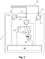
- FIG. 3 shows a further embodiment of the vacuum device 1.
- the vacuum device 1 from FIG. 3 is constructed in a basically similar manner as the vacuum device 1 according to FIG. 1 but additionally includes a valve unit 16 operatively coupled to the control unit and controlled by the control unit 12.
- the vacuum supply line 16 is alternatively connected to the vacuum generator 10 (shown position) for establishing and maintaining the negative pressure or with the environment for venting and for reducing the negative pressure in the vacuum cavity 20.
- the vacuum device 11 further includes an optional flow sensor 17, which is arranged fluidly between the device-side vacuum interface 13 and the valve unit.
- the flow sensor 17 is used to detect fault conditions, in particular temporary or permanent leakages, which cause an increased air flow during the extraction of air from the vacuum cavity 20.
- the presence of a pseudo-vacuum according to the previously described type causes the second pressure sensor 15 to measure a negative pressure during operation of the vacuum generator 10, but no or only a reduced air flow through the flow sensor 17 takes place compared to the situation without a pseudo-vacuum.
- the pressure sensor 11 instead of within a housing (not referenced) of the control unit 1 can be arranged directly on or in the patient interface 2, wherein the pressure sensor connection line 23 is omitted and instead an electrical pressure sensor connection line is provided.
- the pressure sensor 11 may be, for example, a miniaturized one-way pressure sensor, which, for. B. firmly with the patient interface body 2 'is installed, or the patient interface body 2' or the vacuum cavity 20 anyway the pressure sensor 11 have a non-destructive at least for the pressure sensor 11 detachable fluidic interface.
- the device-side vacuum interface 13 and the device-side pressure sensor interface 14 may also be located at the interface to the patient interface body 2 'instead of a housing of the vacuum device 1.
- the vacuum connection line 22 and the pressure sensor connection line 23 may be part of the vacuum device 1 in whole or in part.
- the fluidic interfaces 13, 14 can be realized by means of separate fluidic couplers, for example separate fluidic connectors, or integrated into a common fluidic coupler or connector.
- the structure, in particular the fluidic structure of the vacuum device 1, can also be modified and in particular comprise further components.
- the valve assembly 16 according to FIG. 3 include further valves and allow further fluidic configuration.
- it may be provided to fluidly connect the vacuum generator 10 with the environment.
- the vacuum supply line 22 z. B. fluidly with the connected second pressure sensor 15 or fluidly isolate.
- a vacuum reservoir having a volume in a range of z. B. a liter can be provided, which is connected by means of the valve assembly with the vacuum supply line 22 and / or the vacuum generator 10.
- Such a vacuum reservoir is used in particular for fluidic buffering and may further in place and in basically the same function as the vacuum generator for sucking small amounts of air, for example in the event of a minor and short-term leakage of the vacuum cavity 20.
- the construction of a negative pressure in the optional vacuum reservoir is advantageously carried out by means of the vacuum generator 10th
- FIG. 4 schematically depicts a part of a patient interface 2 according to an exemplary embodiment of the invention together with a patient's eye E.
- the patient interface 2 has a patient interface body 2 'with an annular vacuum cavity 20 and an interior 21. Separate into the vacuum cavity two fluidic connecting pieces 22a, 23a, which with the patienteninterface bathen end of the vacuum connection line 22 and the pressure sensor connection line 23 in basically known Way are fluidly connected tightly, z. B. by gluing, ultrasonic welding, or by frictional engagement.
- the device-side ends of the fluidic conduits 22, 23 terminate in a common vacuum device coupler 25 in the form of a connector which, in use, is coupled to a corresponding patient interface coupler of the vacuum device 1 in the form of a fluidic coupling sleeve.
- the vacuum device coupler 25 and the associated patient interface coupler are dual connectors designed to co-fabricate two fluidly separate connections. Although such a double connector from the standpoint of reliability and handling is advantageous, alternatively, two separate coupler, z. As simple fluidic connectors, can be provided.
- the patient interface 2 according to FIG. 4
- the drip chamber separates fluid sucked from the vacuum cavity 20, for example drops of physiological saline solution as coupling fluid, and thus prevents them from entering the fluidic components of the vacuum device 1 during operation.
- the drip chamber 24 Since the drip chamber 24 is arranged fluidically between the vacuum cavity 20 and the second pressure sensor 15, it slows down the response of the second pressure sensor 15 and increases its inertia. However, this does not apply to the directly coupled to the vacuum volume 20 pressure sensor 11, which thus reacts to pressure changes in the vacuum volume 20 faster.
- FIG. 5 illustrates another embodiment of an ophthalmic device having another embodiment of the vacuum device 1 and another embodiment of the patient interface 2 in a schematic functional representation and in operatively coupled state.
- the vacuum device 1 and the patient interface 2 after FIG. 5 analogous to the representation according to FIG. 1 be constructed and possess appropriate functionality.
- the fluidic pressure sensor 11 is replaced by a contact pressure sensor 11 ', which is arranged in the patient interface 2.
- the contact pressure sensor 11 ' is designed for measuring the contract pressure between the patient interface 2 and the patient's eye and, for example, integrally integrated into the side of a wall of the suction ring facing the patient's eye.
- a plurality of isolated contact pressure sensors along the circumference of the suction ring or even a single isolated contact pressure sensor may be provided.
- the fluidic pressure sensor connection line 23 of FIG. 1 is replaced in this form by an electrical pressure sensor connecting line 23 ', via which the contact pressure sensor 11' is functionally electrically coupled to the vacuum device 1. Accordingly, instead of the fluidic device side pressure sensor interface 14 according to FIG. 1 an electrical device side pressure sensor interface 14 ', e.g. B. in the form of an electrical connector provided. A fluidic pressure sensor 11 according to FIG. 1 can optionally be additionally provided.
Landscapes
- Health & Medical Sciences (AREA)
- Life Sciences & Earth Sciences (AREA)
- Physics & Mathematics (AREA)
- Ophthalmology & Optometry (AREA)
- Optics & Photonics (AREA)
- General Health & Medical Sciences (AREA)
- Heart & Thoracic Surgery (AREA)
- Biomedical Technology (AREA)
- Surgery (AREA)
- Animal Behavior & Ethology (AREA)
- Engineering & Computer Science (AREA)
- Public Health (AREA)
- Veterinary Medicine (AREA)
- Nuclear Medicine, Radiotherapy & Molecular Imaging (AREA)
- Vascular Medicine (AREA)
- Molecular Biology (AREA)
- Biophysics (AREA)
- Medical Informatics (AREA)
- Eye Examination Apparatus (AREA)
Priority Applications (1)
| Application Number | Priority Date | Filing Date | Title |
|---|---|---|---|
| EP16168672.0A EP3092986B1 (fr) | 2015-05-11 | 2016-05-09 | Dispositif ophtalmologique a vide et interface patient |
Applications Claiming Priority (2)
| Application Number | Priority Date | Filing Date | Title |
|---|---|---|---|
| EP15167073 | 2015-05-11 | ||
| EP16168672.0A EP3092986B1 (fr) | 2015-05-11 | 2016-05-09 | Dispositif ophtalmologique a vide et interface patient |
Publications (4)
| Publication Number | Publication Date |
|---|---|
| EP3092986A2 true EP3092986A2 (fr) | 2016-11-16 |
| EP3092986A3 EP3092986A3 (fr) | 2017-02-22 |
| EP3092986B1 EP3092986B1 (fr) | 2023-06-14 |
| EP3092986C0 EP3092986C0 (fr) | 2023-06-14 |
Family
ID=53174847
Family Applications (1)
| Application Number | Title | Priority Date | Filing Date |
|---|---|---|---|
| EP16168672.0A Active EP3092986B1 (fr) | 2015-05-11 | 2016-05-09 | Dispositif ophtalmologique a vide et interface patient |
Country Status (2)
| Country | Link |
|---|---|
| US (1) | US10238287B2 (fr) |
| EP (1) | EP3092986B1 (fr) |
Families Citing this family (1)
| Publication number | Priority date | Publication date | Assignee | Title |
|---|---|---|---|---|
| US10195085B2 (en) * | 2014-10-17 | 2019-02-05 | Optimedica Corporation | Vacuum loss detection during laser eye surgery |
Citations (6)
| Publication number | Priority date | Publication date | Assignee | Title |
|---|---|---|---|---|
| US20020120285A1 (en) | 2001-02-23 | 2002-08-29 | Ras Holding Corp | Surgical blade for use with a surgical tool for making incisions for scleral eye implants |
| US20020198553A1 (en) | 2001-06-22 | 2002-12-26 | Nidek Co., Ltd. | Corneal surgical apparatus |
| EP1731120A1 (fr) | 2005-06-09 | 2006-12-13 | SIE AG, Surgical Instrument Engineering | Dispositif ophthalmologique destiné à l'ablation de tissus des yeux. |
| WO2008150330A1 (fr) | 2007-06-04 | 2008-12-11 | Oraya Therapeutics, Inc. | Dispositif et ensemble pour le positionnement, la stabilisation et le traitement d'un oeil |
| WO2012031277A1 (fr) | 2010-09-02 | 2012-03-08 | Optimedica Corporation | Interface patient pour un diagnostic ophtalmologique et des interventions chirurgicales |
| US20150088103A1 (en) | 2013-09-26 | 2015-03-26 | Ziemer Ophthalmic Systems Ag | Patient Interface for Ophthalmological, Optical Therapy and Diagnosis Device |
Family Cites Families (3)
| Publication number | Priority date | Publication date | Assignee | Title |
|---|---|---|---|---|
| US8632526B2 (en) * | 2007-11-07 | 2014-01-21 | Amo Development, Llc | System and method of interfacing a surgical laser with an eye |
| AU2010258305B2 (en) * | 2009-06-09 | 2014-11-20 | Koninklijke Philips Electronics N.V. | Interface appliance carrying one or more sensors detecting parameters related to a flow of fluid delivered through the appliance |
| CA2812827C (fr) * | 2010-09-30 | 2015-12-29 | Alcon Inc. | Dispositif destine a la chirurgie de l'oeil |
-
2016
- 2016-05-09 EP EP16168672.0A patent/EP3092986B1/fr active Active
- 2016-05-10 US US15/151,187 patent/US10238287B2/en active Active
Patent Citations (7)
| Publication number | Priority date | Publication date | Assignee | Title |
|---|---|---|---|---|
| US20020120285A1 (en) | 2001-02-23 | 2002-08-29 | Ras Holding Corp | Surgical blade for use with a surgical tool for making incisions for scleral eye implants |
| US20020198553A1 (en) | 2001-06-22 | 2002-12-26 | Nidek Co., Ltd. | Corneal surgical apparatus |
| EP1731120A1 (fr) | 2005-06-09 | 2006-12-13 | SIE AG, Surgical Instrument Engineering | Dispositif ophthalmologique destiné à l'ablation de tissus des yeux. |
| WO2008150330A1 (fr) | 2007-06-04 | 2008-12-11 | Oraya Therapeutics, Inc. | Dispositif et ensemble pour le positionnement, la stabilisation et le traitement d'un oeil |
| WO2012031277A1 (fr) | 2010-09-02 | 2012-03-08 | Optimedica Corporation | Interface patient pour un diagnostic ophtalmologique et des interventions chirurgicales |
| US20150088103A1 (en) | 2013-09-26 | 2015-03-26 | Ziemer Ophthalmic Systems Ag | Patient Interface for Ophthalmological, Optical Therapy and Diagnosis Device |
| EP2853247A1 (fr) | 2013-09-26 | 2015-04-01 | Ziemer Ophthalmic Systems AG | Inteface patient pour un dispositif ophtalmique, optique de traitement ou diagnose |
Also Published As
| Publication number | Publication date |
|---|---|
| EP3092986B1 (fr) | 2023-06-14 |
| EP3092986A3 (fr) | 2017-02-22 |
| US20160331231A1 (en) | 2016-11-17 |
| EP3092986C0 (fr) | 2023-06-14 |
| US10238287B2 (en) | 2019-03-26 |
Similar Documents
| Publication | Publication Date | Title |
|---|---|---|
| EP3266427B1 (fr) | Dispositif a vide et procede de surveillance d'une interface de patient ophtalmologique | |
| DE60109824T2 (de) | Ausrichtungsleitsystem | |
| DE699515C (de) | aetigkeit | |
| DE3838689C1 (en) | Method for the continuous measurement of the pressure in a flexible fluid line for medical purposes, as well as a device for carrying out the method | |
| WO2019069204A3 (fr) | Système, appareil et procédé de maintien de la pression intraoculaire peropératoire de la chambre antérieure | |
| CH644260A5 (de) | Blutdruckmesseinrichtung. | |
| DE4219888A1 (de) | Durchfluß-Druckwandler | |
| EP2913073B1 (fr) | Dispositif destinés à la détection d'une déconnexion d'aiguille veineuse | |
| DE60130284T2 (de) | Verfahren der berührungslosen Tonometrie | |
| CH673760A5 (fr) | ||
| EP3214992B1 (fr) | Systeme de surveillance | |
| DE102013202540A1 (de) | Verfahren zum Betrieb einer Aufbereitungsvorrichtung und Aufbereitungsvorrichtung für chirurgische Instrumente | |
| WO2019223826A1 (fr) | Dispositif d'insufflation et procédé de fonctionnement pouvant être mis en oeuvre avec celui-ci | |
| DE3855583T2 (de) | Körperhöhlendruckeinstellsystem für ein Endoskop | |
| DE102013108496A1 (de) | Füllstandsüberwachung an einem Flüssigkeitsbeutel | |
| EP3092986B1 (fr) | Dispositif ophtalmologique a vide et interface patient | |
| EP2621421B1 (fr) | Dispositif de chirurgie oculaire | |
| DE102007062861A1 (de) | Befülladapter zum Befüllen eines Cuffs | |
| DE102005058012B4 (de) | Verfahren zum Freiblasen eines benetzten Hydrophobfilters und Vorrichtung zur Durchführung des Verfahrens | |
| EP3501560B1 (fr) | Procédé de fonctionnement d'un système de traitement par sous-pression | |
| EP3606483A1 (fr) | Système de chirurgie oculaire laser à impulsions courtes permettant de traiter un oeil et procédé de détermination de niveau de remplissage d'un liquide dans une cavité d'un système de chirurgie oculaire laser à impulsions courtes | |
| EP3485311B1 (fr) | Dispositif d'essai de l'étanchéité d'un instrument chirurgical, dispositif de préparation destiné à la préparation des instruments chirurgicaux et utilisation d'un élément gonflable | |
| WO2025026807A1 (fr) | Œil test à pression ajustable pour des tonomètres | |
| DE4131401C1 (en) | Monitoring pressure sensors for controlled or regulated pressure generator - detecting width of deviation of pressure signal from sensor under test and comparing with stipulated range related to control valves | |
| DE102012009078A1 (de) | Insufflationsvorrichtung und Verfahren |
Legal Events
| Date | Code | Title | Description |
|---|---|---|---|
| PUAI | Public reference made under article 153(3) epc to a published international application that has entered the european phase |
Free format text: ORIGINAL CODE: 0009012 |
|
| AK | Designated contracting states |
Kind code of ref document: A2 Designated state(s): AL AT BE BG CH CY CZ DE DK EE ES FI FR GB GR HR HU IE IS IT LI LT LU LV MC MK MT NL NO PL PT RO RS SE SI SK SM TR |
|
| AX | Request for extension of the european patent |
Extension state: BA ME |
|
| PUAL | Search report despatched |
Free format text: ORIGINAL CODE: 0009013 |
|
| AK | Designated contracting states |
Kind code of ref document: A3 Designated state(s): AL AT BE BG CH CY CZ DE DK EE ES FI FR GB GR HR HU IE IS IT LI LT LU LV MC MK MT NL NO PL PT RO RS SE SI SK SM TR |
|
| AX | Request for extension of the european patent |
Extension state: BA ME |
|
| RIC1 | Information provided on ipc code assigned before grant |
Ipc: A61F 9/013 20060101AFI20170116BHEP Ipc: A61F 9/009 20060101ALI20170116BHEP |
|
| STAA | Information on the status of an ep patent application or granted ep patent |
Free format text: STATUS: REQUEST FOR EXAMINATION WAS MADE |
|
| 17P | Request for examination filed |
Effective date: 20170807 |
|
| RBV | Designated contracting states (corrected) |
Designated state(s): AL AT BE BG CH CY CZ DE DK EE ES FI FR GB GR HR HU IE IS IT LI LT LU LV MC MK MT NL NO PL PT RO RS SE SI SK SM TR |
|
| STAA | Information on the status of an ep patent application or granted ep patent |
Free format text: STATUS: EXAMINATION IS IN PROGRESS |
|
| 17Q | First examination report despatched |
Effective date: 20200320 |
|
| GRAP | Despatch of communication of intention to grant a patent |
Free format text: ORIGINAL CODE: EPIDOSNIGR1 |
|
| STAA | Information on the status of an ep patent application or granted ep patent |
Free format text: STATUS: GRANT OF PATENT IS INTENDED |
|
| INTG | Intention to grant announced |
Effective date: 20220524 |
|
| GRAJ | Information related to disapproval of communication of intention to grant by the applicant or resumption of examination proceedings by the epo deleted |
Free format text: ORIGINAL CODE: EPIDOSDIGR1 |
|
| STAA | Information on the status of an ep patent application or granted ep patent |
Free format text: STATUS: EXAMINATION IS IN PROGRESS |
|
| INTC | Intention to grant announced (deleted) | ||
| GRAP | Despatch of communication of intention to grant a patent |
Free format text: ORIGINAL CODE: EPIDOSNIGR1 |
|
| STAA | Information on the status of an ep patent application or granted ep patent |
Free format text: STATUS: GRANT OF PATENT IS INTENDED |
|
| INTG | Intention to grant announced |
Effective date: 20221027 |
|
| GRAS | Grant fee paid |
Free format text: ORIGINAL CODE: EPIDOSNIGR3 |
|
| GRAA | (expected) grant |
Free format text: ORIGINAL CODE: 0009210 |
|
| STAA | Information on the status of an ep patent application or granted ep patent |
Free format text: STATUS: THE PATENT HAS BEEN GRANTED |
|
| AK | Designated contracting states |
Kind code of ref document: B1 Designated state(s): AL AT BE BG CH CY CZ DE DK EE ES FI FR GB GR HR HU IE IS IT LI LT LU LV MC MK MT NL NO PL PT RO RS SE SI SK SM TR |
|
| REG | Reference to a national code |
Ref country code: CH Ref legal event code: EP |
|
| P01 | Opt-out of the competence of the unified patent court (upc) registered |
Effective date: 20230513 |
|
| REG | Reference to a national code |
Ref country code: DE Ref legal event code: R096 Ref document number: 502016015864 Country of ref document: DE |
|
| REG | Reference to a national code |
Ref country code: AT Ref legal event code: REF Ref document number: 1578687 Country of ref document: AT Kind code of ref document: T Effective date: 20230715 |
|
| U01 | Request for unitary effect filed |
Effective date: 20230614 |
|
| U07 | Unitary effect registered |
Designated state(s): AT BE BG DE DK EE FI FR IT LT LU LV MT NL PT SE SI Effective date: 20230619 |
|
| P04 | Withdrawal of opt-out of the competence of the unified patent court (upc) registered |
Effective date: 20230623 |
|
| REG | Reference to a national code |
Ref country code: LT Ref legal event code: MG9D |
|
| PG25 | Lapsed in a contracting state [announced via postgrant information from national office to epo] |
Ref country code: NO Free format text: LAPSE BECAUSE OF FAILURE TO SUBMIT A TRANSLATION OF THE DESCRIPTION OR TO PAY THE FEE WITHIN THE PRESCRIBED TIME-LIMIT Effective date: 20230914 Ref country code: ES Free format text: LAPSE BECAUSE OF FAILURE TO SUBMIT A TRANSLATION OF THE DESCRIPTION OR TO PAY THE FEE WITHIN THE PRESCRIBED TIME-LIMIT Effective date: 20230614 |
|
| PG25 | Lapsed in a contracting state [announced via postgrant information from national office to epo] |
Ref country code: RS Free format text: LAPSE BECAUSE OF FAILURE TO SUBMIT A TRANSLATION OF THE DESCRIPTION OR TO PAY THE FEE WITHIN THE PRESCRIBED TIME-LIMIT Effective date: 20230614 Ref country code: HR Free format text: LAPSE BECAUSE OF FAILURE TO SUBMIT A TRANSLATION OF THE DESCRIPTION OR TO PAY THE FEE WITHIN THE PRESCRIBED TIME-LIMIT Effective date: 20230614 Ref country code: GR Free format text: LAPSE BECAUSE OF FAILURE TO SUBMIT A TRANSLATION OF THE DESCRIPTION OR TO PAY THE FEE WITHIN THE PRESCRIBED TIME-LIMIT Effective date: 20230915 |
|
| PG25 | Lapsed in a contracting state [announced via postgrant information from national office to epo] |
Ref country code: SK Free format text: LAPSE BECAUSE OF FAILURE TO SUBMIT A TRANSLATION OF THE DESCRIPTION OR TO PAY THE FEE WITHIN THE PRESCRIBED TIME-LIMIT Effective date: 20230614 |
|
| PG25 | Lapsed in a contracting state [announced via postgrant information from national office to epo] |
Ref country code: IS Free format text: LAPSE BECAUSE OF FAILURE TO SUBMIT A TRANSLATION OF THE DESCRIPTION OR TO PAY THE FEE WITHIN THE PRESCRIBED TIME-LIMIT Effective date: 20231014 |
|
| PG25 | Lapsed in a contracting state [announced via postgrant information from national office to epo] |
Ref country code: SM Free format text: LAPSE BECAUSE OF FAILURE TO SUBMIT A TRANSLATION OF THE DESCRIPTION OR TO PAY THE FEE WITHIN THE PRESCRIBED TIME-LIMIT Effective date: 20230614 Ref country code: SK Free format text: LAPSE BECAUSE OF FAILURE TO SUBMIT A TRANSLATION OF THE DESCRIPTION OR TO PAY THE FEE WITHIN THE PRESCRIBED TIME-LIMIT Effective date: 20230614 Ref country code: RO Free format text: LAPSE BECAUSE OF FAILURE TO SUBMIT A TRANSLATION OF THE DESCRIPTION OR TO PAY THE FEE WITHIN THE PRESCRIBED TIME-LIMIT Effective date: 20230614 Ref country code: IS Free format text: LAPSE BECAUSE OF FAILURE TO SUBMIT A TRANSLATION OF THE DESCRIPTION OR TO PAY THE FEE WITHIN THE PRESCRIBED TIME-LIMIT Effective date: 20231014 Ref country code: CZ Free format text: LAPSE BECAUSE OF FAILURE TO SUBMIT A TRANSLATION OF THE DESCRIPTION OR TO PAY THE FEE WITHIN THE PRESCRIBED TIME-LIMIT Effective date: 20230614 |
|
| PG25 | Lapsed in a contracting state [announced via postgrant information from national office to epo] |
Ref country code: PL Free format text: LAPSE BECAUSE OF FAILURE TO SUBMIT A TRANSLATION OF THE DESCRIPTION OR TO PAY THE FEE WITHIN THE PRESCRIBED TIME-LIMIT Effective date: 20230614 |
|
| REG | Reference to a national code |
Ref country code: DE Ref legal event code: R097 Ref document number: 502016015864 Country of ref document: DE |
|
| PLBE | No opposition filed within time limit |
Free format text: ORIGINAL CODE: 0009261 |
|
| STAA | Information on the status of an ep patent application or granted ep patent |
Free format text: STATUS: NO OPPOSITION FILED WITHIN TIME LIMIT |
|
| 26N | No opposition filed |
Effective date: 20240315 |
|
| U20 | Renewal fee for the european patent with unitary effect paid |
Year of fee payment: 9 Effective date: 20240527 |
|
| P05 | Withdrawal of opt-out of the competence of the unified patent court (upc) changed |
Free format text: CASE NUMBER: APP_528263/2023 Effective date: 20230619 |
|
| PG25 | Lapsed in a contracting state [announced via postgrant information from national office to epo] |
Ref country code: MC Free format text: LAPSE BECAUSE OF FAILURE TO SUBMIT A TRANSLATION OF THE DESCRIPTION OR TO PAY THE FEE WITHIN THE PRESCRIBED TIME-LIMIT Effective date: 20230614 |
|
| PG25 | Lapsed in a contracting state [announced via postgrant information from national office to epo] |
Ref country code: MC Free format text: LAPSE BECAUSE OF FAILURE TO SUBMIT A TRANSLATION OF THE DESCRIPTION OR TO PAY THE FEE WITHIN THE PRESCRIBED TIME-LIMIT Effective date: 20230614 |
|
| PG25 | Lapsed in a contracting state [announced via postgrant information from national office to epo] |
Ref country code: IE Free format text: LAPSE BECAUSE OF NON-PAYMENT OF DUE FEES Effective date: 20240509 |
|
| U20 | Renewal fee for the european patent with unitary effect paid |
Year of fee payment: 10 Effective date: 20250528 |
|
| PGFP | Annual fee paid to national office [announced via postgrant information from national office to epo] |
Ref country code: GB Payment date: 20250527 Year of fee payment: 10 |
|
| PGFP | Annual fee paid to national office [announced via postgrant information from national office to epo] |
Ref country code: CH Payment date: 20250601 Year of fee payment: 10 |
|
| PG25 | Lapsed in a contracting state [announced via postgrant information from national office to epo] |
Ref country code: CY Free format text: LAPSE BECAUSE OF FAILURE TO SUBMIT A TRANSLATION OF THE DESCRIPTION OR TO PAY THE FEE WITHIN THE PRESCRIBED TIME-LIMIT; INVALID AB INITIO Effective date: 20160509 |
|
| PG25 | Lapsed in a contracting state [announced via postgrant information from national office to epo] |
Ref country code: HU Free format text: LAPSE BECAUSE OF FAILURE TO SUBMIT A TRANSLATION OF THE DESCRIPTION OR TO PAY THE FEE WITHIN THE PRESCRIBED TIME-LIMIT; INVALID AB INITIO Effective date: 20160509 |