EP3093045A1 - Teilchenstrahlbestrahlungsvorrichtung - Google Patents
Teilchenstrahlbestrahlungsvorrichtung Download PDFInfo
- Publication number
- EP3093045A1 EP3093045A1 EP14877990.3A EP14877990A EP3093045A1 EP 3093045 A1 EP3093045 A1 EP 3093045A1 EP 14877990 A EP14877990 A EP 14877990A EP 3093045 A1 EP3093045 A1 EP 3093045A1
- Authority
- EP
- European Patent Office
- Prior art keywords
- irradiation
- particle beam
- dose
- irradiation position
- rescan
- Prior art date
- Legal status (The legal status is an assumption and is not a legal conclusion. Google has not performed a legal analysis and makes no representation as to the accuracy of the status listed.)
- Withdrawn
Links
Images




Classifications
-
- A—HUMAN NECESSITIES
- A61—MEDICAL OR VETERINARY SCIENCE; HYGIENE
- A61N—ELECTROTHERAPY; MAGNETOTHERAPY; RADIATION THERAPY; ULTRASOUND THERAPY
- A61N5/00—Radiation therapy
- A61N5/10—X-ray therapy; Gamma-ray therapy; Particle-irradiation therapy
- A61N5/1042—X-ray therapy; Gamma-ray therapy; Particle-irradiation therapy with spatial modulation of the radiation beam within the treatment head
- A61N5/1043—Scanning the radiation beam, e.g. spot scanning or raster scanning
-
- A—HUMAN NECESSITIES
- A61—MEDICAL OR VETERINARY SCIENCE; HYGIENE
- A61N—ELECTROTHERAPY; MAGNETOTHERAPY; RADIATION THERAPY; ULTRASOUND THERAPY
- A61N5/00—Radiation therapy
- A61N5/10—X-ray therapy; Gamma-ray therapy; Particle-irradiation therapy
- A61N5/1042—X-ray therapy; Gamma-ray therapy; Particle-irradiation therapy with spatial modulation of the radiation beam within the treatment head
- A61N5/1043—Scanning the radiation beam, e.g. spot scanning or raster scanning
- A61N5/1044—Scanning the radiation beam, e.g. spot scanning or raster scanning with multiple repetitions of the scanning pattern
-
- A—HUMAN NECESSITIES
- A61—MEDICAL OR VETERINARY SCIENCE; HYGIENE
- A61N—ELECTROTHERAPY; MAGNETOTHERAPY; RADIATION THERAPY; ULTRASOUND THERAPY
- A61N5/00—Radiation therapy
- A61N5/10—X-ray therapy; Gamma-ray therapy; Particle-irradiation therapy
- A61N5/1048—Monitoring, verifying, controlling systems and methods
- A61N5/1071—Monitoring, verifying, controlling systems and methods for verifying the dose delivered by the treatment plan
-
- A—HUMAN NECESSITIES
- A61—MEDICAL OR VETERINARY SCIENCE; HYGIENE
- A61N—ELECTROTHERAPY; MAGNETOTHERAPY; RADIATION THERAPY; ULTRASOUND THERAPY
- A61N5/00—Radiation therapy
- A61N5/10—X-ray therapy; Gamma-ray therapy; Particle-irradiation therapy
- A61N2005/1085—X-ray therapy; Gamma-ray therapy; Particle-irradiation therapy characterised by the type of particles applied to the patient
- A61N2005/1087—Ions; Protons
Definitions
- the present invention relates to a particle beam irradiation apparatus used in particle beam therapy systems, for irradiating a diseased portion such as a tumor with a particle beam by a prescribed dose in accordance with the three-dimensional shape of the diseased portion.
- the particle beam therapy is a method of treating a cancer by imparting to a tumor in the body of a patient an irradiation dose of charged particles such as protons or carbon ions accelerated to about several hundred MeV using an apparatus such as an accelerator.
- an apparatus such as an accelerator.
- it is important to form a dose distribution that approximates as much as possible to a target dose distribution prescribed for the tumor by a doctor.
- the target distribution is, in many cases, uniform inside the tumor and as lower as possible outside the tumor than thereinside.
- a three-dimensional dose distribution is generally formed whose characteristic has a maximum dose peak at one point in the object.
- This maximum dose peak is referred to as "Bragg peak”.
- the peak point is defined as "irradiation position" of the particle beam.
- One of the methods of forming a target dose distribution is a scanning irradiation method.
- a mechanism such as electromagnets is basically used that arbitrarily deflects the particle beam in two directions, i.e., in the X- and Y-directions perpendicular to the Z-direction, the traveling direction of the particle beam.
- a function is further needed that arbitrarily varies in the Z-direction the position where the Bragg peak is formed, by adjusting the energy level of the particles.
- the accelerator which is a particle beam generating apparatus, is generally provided with a mechanism of adjusting the energy level.
- a plurality of irradiation positions (also referred to as spots) are set in a tumor, and then each irradiation position is sequentially irradiated with the particle beam using the above two mechanisms.
- Dose balance to be imparted to each irradiation position is preliminarily adjusted so that summation of individual dose distributions imparted to each irradiation position resultantly forms a target dose distribution.
- the ordinary sequence of irradiating each irradiation position is such that all irradiation positions corresponding to an energy level of the beam are irradiated first with the beam of the energy level by scanning the particle beam in the X-Y direction, and then the energy level is changed to a next one.
- the scanning irradiation method is classified into the following methods depending on the way of scanning in the X-Y direction.
- a scanning irradiation method in which the particle beam is interrupted during scan-shifting from an irradiation position to a next irradiation position is called a spot scanning method or a discrete spot scanning method.
- a mechanism for measuring a dose imparted to each irradiation position is provided, and the method is implemented in such a way that the particle beam is once interrupted when a measured dose reaches a prescribed dose to be administered to an irradiation position, and then the particle beam is scan-shifted to a next irradiation position.
- a scanning irradiation method is classified into two methods.
- One is a method in which a mechanism is provided for measuring a dose imparted to each irradiation position, and the particle beam is scan-shifted to a next irradiation position without interrupting the beam at the time when the measured dose reaches to a certain value.
- This method is referred to as a raster scanning method (see, for example, Patent Document 1). Since the irradiation is continued during scan-shifting of the particle beam, the summation of a distribution of doses imparted during scan-shifting and that of doses imparted not during scan-shifting but during staying at irradiation positions is adjusted to a target dose distribution.
- the other method is a line scanning method in the case of no interruption of the particle beam during scan-shifting from an irradiation position to a next irradiation position.
- the irradiation target is irradiated with the particle beam by continuing scanning of the particle beam without staying at each irradiation position.
- Functions of keeping constant the beam intensity, which is a dose imparted per unit time, and of varying the scanning speed arbitrarily are provided for scanning the particle beam at a low speed near an irradiation position to which a high dose to be imparted and at a high speed near an irradiation position to which a low dose to be imparted.
- the resultant summation of a dose distribution is adjusted to be a target distribution.
- a dose distribution actually obtained may not be a target one since there are various uncertainties in practical irradiation.
- the uncertainties are caused such as by instability in the position and intensity of the particle beam, a positional error in fastening a patient, error in CT data of the patient, a signal delay in the control equipment, and noise, for example.
- an actual dose distribution may differ from calculated one.
- a tumor particularly in a liver or a respiratory organ such as a lung, it is difficult to impart an irradiation dose to the tumor in accordance with a treatment plan because the position of the tumor, conditions around the tumor and the like are changing temporally owing to respiration of the patient.
- each irradiation position is dividedly irradiated multiple times with the particle beam.
- the method is based on the concept that error in a dose distribution is canceled out and reduced by summing the multiple time irradiations.
- the number of divided irradiation is referred to as a rescan count.
- the sequence of irradiation is such that the particle beam of an energy level is scanned at first in the X-Y direction to irradiate once all irradiation positions corresponding to the energy level. After that, each irradiation position is irradiated again with the energy level remaining unchanged. The irradiation is repeated for a rescan-count number of times, and then the energy level is changed to a next one.
- the rescan count may be different for each energy level or may be the same for all energy levels. Generally, influence of the error is cancelled out and reduced more as the rescan count is increased.
- Patent Document 1 JP 2009-066 106 A (paragraph [0014])
- Patent Document 2 JP 2008-154 627 A
- the rescanning is applicable to any of the spot scanning method, the raster scanning method, and the line scanning method. In any of the methods, when the rescan count is increased, a single dose to be administered to each irradiation position must be reduced accordingly.
- a lower limit of the dose depends on the maximum scanning speed, the beam intensity, and a distance between irradiation positions. Increasing the rescan count reduces a single dose to be administered to each irradiation position and may cause the single dose to be lower than the lower limit. Even in that case, a dose comparable to the lower limit is necessarily imparted, resulting in occurrence of an excessive dose higher than a planned value.
- the present invention is therefore aimed at providing a particle beam irradiation apparatus that allows for setting a proper rescan count in a raster scanning method or a line scanning method.
- a particle beam irradiation apparatus that comprises:
- a particle beam irradiation apparatus that has a scanning apparatus deflecting a particle beam in two X-Y directions perpendicular to a traveling direction of the beam, to scan the beam two-dimensionally over irradiation positions in an irradiation target to be irradiate with the particle beam; a storage unit storing position information on the irradiation positions, information on a dose to be administered to each irradiation position, and information on scan speed of the scanning apparatus; and a control unit controlling the scanning apparatus, wherein the control unit controls the scanning apparatus so that each irradiation position in the irradiation target are irradiated with the particle beam a rescan-count number of times by repeating for the rescan-count number of times the irradiation of all irradiation positions in a two-dimensional X-Y plane by repeating scan-shifting of the particle beam from a current irradiation position to a next irradiation position at a
- a particle beam irradiation apparatus can be provided that allows for setting a proper rescan count in a raster scanning method and a line scanning method and is thereby capable of performing a high reliability irradiation in a shortest possible time.
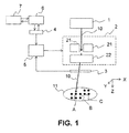
- FIG. 1 is a block diagram showing a schematic configuration of a particle beam irradiation apparatus according to Embodiment 1 of the present invention.
- the particle beam irradiation apparatus according to Embodiment 1 includes a particle beam generating apparatus 1 for generating and accelerating particles as a particle beam 10 to a required energy level; and a scanning apparatus 2 for deflecting the particle beam 10 generated by the particle beam generating apparatus 1 in two directions (X- and Y-directions) perpendicular to the traveling direction (Z-direction) of the particle beam, to scan the particle beam over given positions in an irradiation target 11, i.e., a tumor of a patient.
- an irradiation target 11 i.e., a tumor of a patient.
- the particle beam generating apparatus 1 is ordinarily provided with an accelerator for accelerating the particles and a delivery system for delivering the particle beam 10 from the accelerator to the scanning apparatus 2.
- the particle beam irradiation apparatus further includes a dose monitor 3 for measuring a dose imparted to each position in the irradiation target 11 from the particle beam 10 scanned by the scanning apparatus 2; a storage unit 4 for storing position information on each irradiation position, information on a dose to be administered to each irradiation position, information on scan speed of the scanning apparatus 2, and the like; a control unit 5 for controlling scanning of the scanning apparatus 2; and a calculation unit 6 for calculating using the information stored in the storage unit 4 a rescan count or a beam intensity from a beam intensity or a rescan count input via an input/output unit 7.
- the position information to be stored in the storage unit 4 includes, for example, irradiation position numbers, the X- and Y-coordinates of each irradiation position, current values for energizing the scanning electromagnets in the scanning apparatus 2 to deflect the particle beam to each irradiation position in the X-Y direction, an energy level corresponding to the Z-coordinate of each irradiation position, and the like.
- the particle beam irradiation apparatus is for implementing a raster scanning method. Operation of the particle beam irradiation apparatus will be described hereinafter. The outline of the raster scanning method is described first with reference to FIGS. 1 and 2.
- FIG. 2 illustrates how an irradiation position A , an irradiation position B, and an irradiation position C shown in FIG. 1 are irradiated sequentially.
- the horizontal axis represents time and the vertical axis represents irradiation positions, and the position of the particle beam 10 scan-shifting with time is indicated by the white arrows.
- control unit 5 controls the Y-direction electromagnet 21 and the X-direction electromagnet 22 of the scanning apparatus 2 for the particle beam to stay at the irradiation position A.
- the control unit 5 controls the scanning apparatus 2 to scan-shift the particle beam 10 to the irradiation position B.
- the control unit controls the particle beam to stay there. And then when the dose measured with the dose monitor 3 reaches a target dose to the irradiation position B, the control unit controls the scanning apparatus 2 to scan-shift the particle beam 10 to the irradiation position C. While the particle beam 10 is being scan-shifted, i.e., during scanning, the irradiation target (diseased portion) 11 is kept irradiated with the particle beam.
- all irradiation positions in the two-dimensional X-Y plane at a Z-positon of a tumor, i.e., a diseased region can be irradiated with the particle beam.
- all irradiation positions in the two-dimensional X-Y plane at a Z-positon are irradiated multiple times with the particle beam with its energy level being kept constant, that is, rescanning is performed.
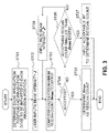
- FIG. 3 is a flow diagram showing a method of determining the rescan count when the beam intensity is fixed in advance.
- each irradiation position i in a tumor and a dose d i to be imparted to each irradiation position are determined on the basis of CT information of a patient and the position information of the tumor (Step ST01 ). These positions and the doses are ordinarily determined by a calculation apparatus referred to as "treatment planning apparatus" and stored in the storage unit 4.
- the dose d i to be administered to each irradiation position is defined not as a single dose to be imparted during one scanning divided multiply but as the total of doses to be imparted multiple times to each irradiation position. Accordingly, assuming that the rescan count is n , a single dose to be imparted is expressed as d i / n .
- a user of the particle beam irradiation apparatus inputs a beam intensity J to be used for treatment to the calculation unit 6 via the input/output unit 7 before starting the treatment (Step ST02 ).
- the calculation unit 6 calculates a time t i required for scan-shifting from an irradiation position i-1 to a next irradiation position, on the basis of the position information on each irradiation position i , the information on a dose d i to be administered to an irradiation position i, and the information on the scan speed for the scanning apparatus 2 to scan the particle beam.
- x i , x i-1 and y i , y i-1 represent the X- and Y-coordinates of the irradiation positions i , and i-1 , respectively; and V x and V y represent scan speeds in the X- and Y-directions, respectively, by the scanning apparatus.
- the max [ a, b] is an operator that selects a larger one among a and b. Note that the equation (1) could be a different equation depending on the characteristics of the scanning apparatus 2 and the control unit 5.
- a single dose to be administered to each irradiation position must be larger than an actual dose to be imparted during scan-shifting. That is, the following conditional expression (P1) must hold true for all irradiation positions i 's, except for an irradiation position i to be irradiated first among irradiation positions corresponding to an energy level.
- J is a beam intensity input as a dose to be imparted per unit time.
- n max int min i d i / J ⁇ t i wherein the operator int [ r ] expresses a maximum integer not exceeding a real number r, and the operator min ( i )[ f ( i )] expresses a minimum value among f ( i )'s for all i 's.
- the calculation unit 6 outputs the above-calculated n max to the input/output unit 7 to present it to the user (Step ST03).
- the user sees the value of n max and if accepts it ("YES" in Step ST04), the n max is determined as a rescan count N (Step ST05 ). Then, information on the determined count is sent to the storage unit 4 or the control unit 5.
- Step ST06 The user sees the n max and if it is decided that a rescan count n * smaller than the n max is sufficient ("YES" in Step ST06), the user may input anew the modified rescan count n *, to determine the n * as the rescan count N (Step ST07 ). Then, the rescan count information may be sent to the storage unit 4 or the control unit 5.
- Step ST06 the user may input anew a smaller beam intensity J * (Step ST08 ). Then, the calculation unit 6 executes Step ST03 to recalculate an n max .
- irradiation is performed in accordance with the flow diagram shown in FIG. 4 .
- a parameter of the particle beam generating apparatus 1 is set for the particle beam to have an initial energy level to irradiate (Step ST10 ).
- a parameter of the scanning apparatus 2 is set for the particle beam to be located at an initial irradiation position corresponding to the initial energy level (Step ST11 ). Then, the particle beam is generated to start irradiation, and the dose measurement with the dose monitor 3 is started at the same time (Step ST12 ).
- Step ST13 determination is made whether or not the irradiation position is the last irradiation position for the beam energy level (Step ST14 ). If not the last irradiation position ("NO" in Step ST14 ), the particle beam is scan-shifted to a next irradiation position by controlling the parameter of the scanning apparatus 2. At the same time that the scan-shifting is started from an irradiation position i 0 to a next irradiation position i 1 , the dose monitor 3 starts the dose measurement.
- Step ST15 When the beam is scan-shifted to the irradiation position i 1 , the scan-shifting is stopped and the beam stays at the irradiation position i 1 , with the dose measurement being continued (Step ST15 ).
- the control unit 5 commands start of scan-shifting to a next irradiation position i 2 and the dose monitor 3 starts anew the dose measurement at the same time (Step ST15 ).
- the measured dose may be reset in the same measurement mechanism as with the irradiation position i 1 before the dose measurement may be started anew. If the reset time causes a problem, two dose monitors 3 may be used one after another to measure a dose to each irradiation position. In either case, the control is performed so that the summation of a dose imparted during scan-shifting from the irradiation position i-1 to the irradiation position i and that imparted during staying at the irradiation position i equals a single dose d i / n to be imparted to the irradiation position i .
- Step ST14 After one irradiation scanning is finished for all irradiation positions corresponding to an energy level, ("YES" in Step ST14 ), determination is made whether or not the irradiation is performed the determined rescan-count number of times (Step ST16 ). If the determined rescan-count irradiation are not finished ("NO" in Step ST16 ), the process returns to Step ST11 to perform the second irradiation, the third irradiation, ... for each irradiation position corresponding to the same energy level.
- Step ST16 If all the irradiation positions corresponding to the energy level are irradiated the determined rescan-count number of times N ("YES" in Step ST16 ), the beam is interrupted (Step ST17 ). Then, determination is made whether or not the energy level is a last one (Step ST18 ). If the energy level is not the last one ("NO" in Step ST18 ), the parameter of the particle beam generating apparatus 1 is changed for the particle beam to have a next energy level (Step ST19 ).
- the value of d i / n may be stored in the storage unit 4 after the maximum rescan count n max is calculated.
- the control unit 5 can acquire the d i / n max , that is, a dose to be administered during one scanning to each irradiation position can be calculated from the total dose to be administered to each irradiation position, any method may be employed for storing and communicating the information on these values.
- the calculation unit 6 and the storage unit 4 may be made up of other hardware units to have individually the information about the dose to be administered, or may be configured such that only either one has the information to share the information by means of communication when needed. Otherwise, the calculation unit 6 and the storage unit 4 may be made up of a one hardware unit.
- a maximum rescan count is calculated on the basis of an input beam intensity, a scan-shifting time of the particle beam, and a dose to be imparted to each irradiation position, thus providing a particle beam irradiation apparatus that is capable of performing a highly reliable irradiation in a shortest possible time.
- FIG. 5 is a flow diagram showing a calculation procedure of a particle beam irradiation apparatus according to Embodiment 2 of the present invention.
- the configuration of the apparatus is the same as Embodiment 1. While Embodiment 1 is for implementing the method of determining an optimum rescan count in the case of a beam intensity being predetermined, Embodiment 2 is for implementing a method of determining an optimum beam intensity in the case of a rescan count being predetermined.
- the user inputs a predetermined rescan count n to the calculation unit 6 via the input/output unit 7 (Step ST 22).
- the calculation unit outputs a maximum beam intensity that satisfies the conditional expression (P1) for all irradiation positions i (Step ST23 ).
- the conditional expression (P1) is transformed into the following Expression (4): J ⁇ d i / n ⁇ t i
- J max min i d i / n ⁇ t i
- the calculation unit 6 outputs directly the maximum particle beam intensity J max calculated from the above Equation (5). However, if the beam intensity extractable from the particle beam generating apparatus 1 is limited to discrete values, the calculation unit 6 needs to output as a J max a maximum beam intensity that satisfies the Equation (5) among settable beam intensities.
- Step ST24 If the user accepts the output value of J max ("YES" in Step ST24 ), the J max is determined as a beam intensity (Step ST25 ). The procedure for determining beam intensity is now completed, and then the irradiation is started. If the user does not accept the output value of J max ("NO” in Step ST24 ) and decides that a beam intensity lower than the J max is sufficient (“YES” in Step ST26 ), the user may determine an acceptable beam intensity J * as an irradiation beam intensity to input it to the calculation unit 6 (Step ST27 ).
- Step ST26 the user sees the output value of J max and if decides that the J max is insufficient and a large beam intensity is needed ("NO" in Step ST26 ), the user can input anew a smaller rescan count n * (Step ST28 ) for the calculation unit 6 to recalculate a J max .
- a maximum beam intensity is calculated on the basis of an input rescan count, a scan-shifting time of the particle beam, and a dose to be imparted to each irradiation position, thus providing a particle beam irradiation apparatus that is capable of performing a highly reliable irradiation in a shortest possible time.
- the beam intensity is not always constant.
- the particle beam generating apparatus 1 being a synchrotron particle accelerator
- amplitude of the beam intensity fluctuates randomly to some extent with time. Accordingly, a dose possibly varies with time during scanning. For that reason, it is difficult to precisely predict in advance what irradiation position is irradiated at a certain time.
- Embodiment 1 a method of determining a maximum rescan count n max is conceivable in which a margin is set in advance on the basis of the beam intensity fluctuation so that a single dose during scanning does not exceed that to be imparted even if a beam intensity during scanning is higher than the average beam intensity.
- the user inputs an average beam intensity J ave and a margin " margin " to determine a maximum rescan count that satisfies the following conditional expression (P1m), instead of the conditional expression (P1), for all irradiation positions i . margin ⁇ J ⁇ t i ⁇ d i / n That is, the calculation unit 6 calculates the maximum rescan count from the following equation (6) to output.
- n max int min i d i / margin ⁇ J ave ⁇ t i
- the value of " margin " should be properly determined depending on the specification of the particle beam generation unit. For example, in a case of a beam intensity being predicted to fluctuate as shown by the solid line in FIG. 6 , the " margin " is defined as the ratio of the maximum peak beam intensity J p to the average value of J ave .
- a margin is set in advance on the basis of the beam intensity fluctuation, and then the calculation unit calculates from the following Equation (7) a maximum average beam intensity J ave,max that satisfies the conditional expression (P1), to output.
- J ave , max min i d i / n ⁇ t i ⁇ margin
- a margin is set on the basis of fluctuations of the beam intensity to calculate a maximum rescan count or a maximum beam intensity, thus providing a particle beam irradiation apparatus that is capable of performing a highly reliable irradiation in a shortest possible time even when a particle beam generating apparatus is used that emits a beam whose intensity fluctuates.
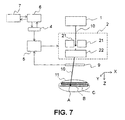
- FIG. 7 is a block diagram showing a schematic configuration of a particle beam irradiation apparatus according to Embodiment 4 of the present invention.
- the particle beam irradiation apparatus according to Embodiment 4 includes a particle beam generating apparatus 1 for generating and accelerating particles as a particle beam 10 to a required energy level; and a scanning apparatus 2 for scanning the particle beam 10 generated by the particle beam generating apparatus 1 over given positions in an irradiation target 11, i.e., a tumor of a patient.
- the particle beam irradiation apparatus further includes a beam position monitor 9 for monitoring the position of the particle beam 10 scanned by the scanning apparatus 2; a storage unit 4 for storing position information on each irradiation position, information on a dose to be administered to each irradiation position, information on scan speed of the scanning apparatus 2, and the like; a control unit 5 for controlling the scanning of the scanning apparatus 2, and a calculation unit 6 for calculating using the information stored in the storage unit 4 a rescan count or a beam intensity from a beam intensity or a rescan count input via an input/output unit 7.
- the position information to be stored in the storage unit 4 includes, for example, irradiation position numbers, the X- and Y-coordinates of each irradiation position, current values for energizing the scanning electromagnets in the scanning apparatus 2 to deflect the particle beam to each irradiation position in the X-Y direction, an energy level corresponding to the Z-coordinate of each irradiation position, and the like.
- Embodiment 4 is for a line scanning method.
- the irradiation is performed while continuing scanning of the particle beam without stopping scan-shifting at each irradiation position.
- a prescribed dose is administered to each irradiation position by scanning the particle beam at a low speed for an irradiation position to which a high dose is to be imparted and at a high speed for an irradiation position to which a low dose is to be imparted, with the beam intensity, which is a dose imparted per unit time, being kept constant.
- FIG. 8 illustrates how the irradiation is performed by the line scanning irradiation method.
- the horizontal axis represents time and the vertical axis represents irradiation positions, and the position of the particle beam 10 scan-shifting with time is indicated by the white arrows. It is assumed here that the distance from an irradiation position A to an irradiation position B and that from the irradiation position B to an irradiation position C are the same.
- the time of scan-shifting from the irradiation position B to the irradiation position C is shorter than that of scan-shifting from the irradiation position A to the irradiation position B, i.e., the speed of scan-shifting from the irradiation position B to the irradiation position C is faster.
- the dose imparted during scan-shifting from the irradiation position B to the irradiation position C is lower than that imparted during scan-shifting from the irradiation position A to the irradiation position B.
- a prescribed dose is administered to each irradiation position, with a dose imparted to each irradiation position being varied by changing the scan-shifting speed depending on an irradiation position.
- t i,mim is defined as a time taken to scan-shift from a given irradiation position i to a next irradiation position i + 1 at a maximum speed.
- conditional expression (P2) is defined using the t i,mim calculated. J ⁇ t i , min ⁇ d i / n
- conditional expression (P2) is satisfied for all irradiation positions i , a lower limit of a dose impartable to each irradiation position is lower than a single dose to be imparted thereto, thus allowing a target dose distribution to be formed, without causing an excessive dose, by adjusting properly the scanning speed.
- n max int min i d i / J ⁇ t i , min
- the user may input a rescan count for the calculation unit 6 to calculate an optimum beam intensity, as with the raster scanning method described in Embodiment 2.
- the calculation unit 6 calculates, from the following equation (10) using the rescan count n input by the user, a maximum beam intensity J max that satisfies the conditional expression (P2) for all i 's, to present the calculated value to the user.
- J max min i d i / n ⁇ t i , min
- either one of a beam intensity J and a rescan count n is input to present a maximum value of the other that satisfies the conditional expression (P2), thus providing a particle beam irradiation apparatus that is capable of performing a highly reliable irradiation in a shortest possible time.
- the rescan count n is constant for each energy level of the particle beam, i.e., for each Z-direction position, for the sake of simplicity.
- the rescan count may, as a matter of course, be different for each energy level. It is known that a dose to be imparted to an irradiation position corresponding to a higher energy level is likely to increase in general. Accordingly, the higher the energy level is, the larger number of times an irradiation position corresponding to the energy level can be rescanned to form a uniform dose distribution.
- the beam intensity is not necessarily constant for all energy levels. For the above reason, increasing the beam intensity for a higher energy level may in some cases be advantageous in shortening the irradiation time. On the other hand, the beam intensity might be essentially difficult to be kept constant for different energy levels, depending on the specification of a particle beam generating apparatus.
- a method of determining a rescan count for each energy level is described taking as an example the raster scanning method of Embodiment 1.
- a single dose to be administered to each irradiation position must be higher than an actual dose to be imparted during scan-shifting.
- conditional expression (P1) for each energy level is expressed below: J e ⁇ t i ⁇ d i / n e
- Step ST04 If the user accepts all these values of n e,max 's ("YES" in Step ST04 shown in FIG. 3 ), these values are determined as rescan counts for respective energy levels. The procedure for determining the rescan counts is now completed. If the user decides that values of n e *'s smaller than part or all of the n e,max 's are sufficient (“YES” in Step ST06), the user inputs the values of n e *'s for the respective rescan counts desired to be modified (Step ST07 ).
- Step ST06 the user inputs anew beam intensities J e * lower than the initial beam intensities J e for rescan counts desired to be modified for respective corresponding energy levels (Step ST08). Then, the computer recalculates rescan counts n e,max for the input beam intensities (Step ST03).
- Step ST24 If the user accepts all these values of J e,max 's ("YES" in Step ST24 shown in FIG. 5 ), these values are determined as beam intensities for the respective energy levels. The procedure for determining the beam intensities is now completed. If the user decides that values of J e *'s smaller than part or all of the J e,max 's are sufficient (“YES” in Step ST26 ), the user inputs the values of J e *'s for respective beam intensities desired to be modified (Step ST27 ).
- Step ST26 the user inputs anew rescan counts n e * lower than the initial rescan counts n e for beam intensities desired to be modified for respective corresponding energy levels (Step ST28 ). Then, the computer recalculates beam intensities J e,max for the input rescan counts (Step ST23 ).
- Embodiment 4 for the line scanning method, rescan counts or beam intensities may be determined for respective energy levels.
Landscapes
- Health & Medical Sciences (AREA)
- Engineering & Computer Science (AREA)
- Biomedical Technology (AREA)
- Pathology (AREA)
- Nuclear Medicine, Radiotherapy & Molecular Imaging (AREA)
- Radiology & Medical Imaging (AREA)
- Life Sciences & Earth Sciences (AREA)
- Animal Behavior & Ethology (AREA)
- General Health & Medical Sciences (AREA)
- Public Health (AREA)
- Veterinary Medicine (AREA)
- Radiation-Therapy Devices (AREA)
Applications Claiming Priority (1)
| Application Number | Priority Date | Filing Date | Title |
|---|---|---|---|
| PCT/JP2014/050295 WO2015104828A1 (ja) | 2014-01-10 | 2014-01-10 | 粒子線照射装置 |
Publications (2)
| Publication Number | Publication Date |
|---|---|
| EP3093045A1 true EP3093045A1 (de) | 2016-11-16 |
| EP3093045A4 EP3093045A4 (de) | 2017-11-01 |
Family
ID=53523676
Family Applications (1)
| Application Number | Title | Priority Date | Filing Date |
|---|---|---|---|
| EP14877990.3A Withdrawn EP3093045A4 (de) | 2014-01-10 | 2014-01-10 | Teilchenstrahlbestrahlungsvorrichtung |
Country Status (6)
| Country | Link |
|---|---|
| US (1) | US9937361B2 (de) |
| EP (1) | EP3093045A4 (de) |
| JP (1) | JP6062073B2 (de) |
| CN (1) | CN105916554A (de) |
| TW (1) | TWI526232B (de) |
| WO (1) | WO2015104828A1 (de) |
Families Citing this family (5)
| Publication number | Priority date | Publication date | Assignee | Title |
|---|---|---|---|---|
| JP6257751B2 (ja) * | 2014-04-10 | 2018-01-10 | 三菱電機株式会社 | 粒子線照射装置 |
| JP6588980B2 (ja) * | 2015-07-01 | 2019-10-09 | 株式会社日立製作所 | 線量分布演算装置、粒子線治療装置、及び線量分布演算方法 |
| WO2017141301A1 (ja) * | 2016-02-15 | 2017-08-24 | 三菱電機株式会社 | 粒子線治療装置および粒子線治療装置の走査回数決定方法 |
| JP2020096647A (ja) * | 2017-03-31 | 2020-06-25 | 住友重機械工業株式会社 | 荷電粒子線治療装置 |
| WO2018211576A1 (ja) * | 2017-05-16 | 2018-11-22 | 株式会社日立製作所 | 粒子線照射装置 |
Family Cites Families (18)
| Publication number | Priority date | Publication date | Assignee | Title |
|---|---|---|---|---|
| US7282427B1 (en) * | 2006-05-04 | 2007-10-16 | Applied Materials, Inc. | Method of implanting a substrate and an ion implanter for performing the method |
| EP2030650B1 (de) * | 2003-05-13 | 2011-11-30 | Hitachi, Ltd. | Behandlungsplanungseinheit zur Teilchenstrahlbestrahlung |
| JP4158931B2 (ja) * | 2005-04-13 | 2008-10-01 | 三菱電機株式会社 | 粒子線治療装置 |
| JP5126770B2 (ja) | 2006-12-20 | 2013-01-23 | 独立行政法人放射線医学総合研究所 | 粒子線照射システム、並びに、これに用いるコンピュータプログラム及びコンピュータ読み取り可能な記憶媒体 |
| US7705977B2 (en) * | 2006-12-21 | 2010-04-27 | Kla-Tencor Corporation | Methods for depth profiling in semiconductors using modulated optical reflectance technology |
| JP2009066106A (ja) | 2007-09-12 | 2009-04-02 | Toshiba Corp | 粒子線ビーム照射装置および粒子線ビーム照射方法 |
| DE102008027485B4 (de) | 2008-06-09 | 2010-02-11 | Gsi Helmholtzzentrum Für Schwerionenforschung Gmbh | Deposition einer Solldosisverteilung in einem zyklisch bewegten Zielgebiet |
| DE102008048916A1 (de) * | 2008-09-26 | 2010-04-29 | Gsi Helmholtzzentrum Für Schwerionenforschung Gmbh | Schnelles Scanning eines Zielgebiets |
| JP5409428B2 (ja) | 2009-03-31 | 2014-02-05 | 株式会社日立製作所 | 荷電粒子照射システム及び照射計画装置 |
| DE102009033297A1 (de) * | 2009-07-15 | 2011-01-20 | Gsi Helmholtzzentrum Für Schwerionenforschung Gmbh | Bestrahlung bzw. Bestrahlungsplanung für ein Rescanning-Verfahren mit einem Partikelstrahl |
| EP2392383B1 (de) | 2010-06-07 | 2014-04-02 | Ion Beam Applications | Vorrichtung zur Teilchenstrahlabgabe |
| US8916838B2 (en) * | 2010-06-07 | 2014-12-23 | Ion Beam Applications Sa | Device and method for particle beam delivery |
| JP5670126B2 (ja) * | 2010-08-26 | 2015-02-18 | 住友重機械工業株式会社 | 荷電粒子線照射装置、荷電粒子線照射方法及び荷電粒子線照射プログラム |
| JP5816518B2 (ja) * | 2011-10-31 | 2015-11-18 | 株式会社日立製作所 | 粒子線照射システム及びビーム補正方法 |
| JP5813207B2 (ja) * | 2012-03-21 | 2015-11-17 | 三菱電機株式会社 | 粒子線スキャニング照射システム |
| EP2939708A4 (de) * | 2012-12-26 | 2016-08-10 | Mitsubishi Electric Corp | Dosisverteilungsmessvorrichtung |
| WO2014210384A1 (en) * | 2013-06-28 | 2014-12-31 | Kla-Tencor Corporation | Selection and use of representative target subsets |
| US9776017B2 (en) * | 2013-07-05 | 2017-10-03 | University Of Iowa Research Foundation | Method and system for dynamically-trimmed spot scanning for ion therapy |
-
2014
- 2014-01-10 JP JP2015556685A patent/JP6062073B2/ja active Active
- 2014-01-10 EP EP14877990.3A patent/EP3093045A4/de not_active Withdrawn
- 2014-01-10 CN CN201480072776.2A patent/CN105916554A/zh active Pending
- 2014-01-10 US US15/110,600 patent/US9937361B2/en active Active
- 2014-01-10 WO PCT/JP2014/050295 patent/WO2015104828A1/ja not_active Ceased
- 2014-04-28 TW TW103115129A patent/TWI526232B/zh not_active IP Right Cessation
Also Published As
| Publication number | Publication date |
|---|---|
| US9937361B2 (en) | 2018-04-10 |
| WO2015104828A1 (ja) | 2015-07-16 |
| JPWO2015104828A1 (ja) | 2017-03-23 |
| TWI526232B (zh) | 2016-03-21 |
| US20160325116A1 (en) | 2016-11-10 |
| TW201526942A (zh) | 2015-07-16 |
| EP3093045A4 (de) | 2017-11-01 |
| CN105916554A (zh) | 2016-08-31 |
| JP6062073B2 (ja) | 2017-01-18 |
Similar Documents
| Publication | Publication Date | Title |
|---|---|---|
| US20190299029A1 (en) | Charged particle beam treatment apparatus | |
| JP5002612B2 (ja) | 荷電粒子ビーム照射装置 | |
| JP6257751B2 (ja) | 粒子線照射装置 | |
| EP3093045A1 (de) | Teilchenstrahlbestrahlungsvorrichtung | |
| US10016623B2 (en) | Particle therapy system and method with parallel control of energy variation and beam position variation | |
| US9265970B2 (en) | Particle beam irradiation system | |
| EP2923733B1 (de) | Teilchenstrahlbestrahlungssystem mit geladenen Teilchen | |
| JP6200368B2 (ja) | 荷電粒子照射システムおよび荷電粒子ビーム照射システムの制御方法 | |
| SG189670A1 (en) | Particle beam irradiation system and charged particle beam correction method | |
| JP2017131399A (ja) | 治療計画装置、治療計画方法、制御装置および粒子線治療システム | |
| JP6009670B2 (ja) | ビーム輸送系及び粒子線治療装置 | |
| CN108348767A (zh) | 粒子束治疗系统 | |
| US11369803B2 (en) | Treatment planning system | |
| JPWO2015155819A1 (ja) | 粒子線治療計画装置、および粒子線照射のシミュレーション方法 | |
| JP2020146334A (ja) | 粒子線治療システム、計測粒子線ct画像生成方法、およびct画像生成プログラム | |
| JP2019055005A (ja) | 粒子線治療システム | |
| JP6839987B2 (ja) | 治療計画装置および粒子線治療システム | |
| JP6494808B2 (ja) | 粒子線治療装置 | |
| JP6063982B2 (ja) | 粒子線治療システム | |
| JP2019180738A (ja) | 粒子線治療システム、及び粒子線治療システムの照射位置制御方法 | |
| JP6063983B2 (ja) | 粒子線治療システム |
Legal Events
| Date | Code | Title | Description |
|---|---|---|---|
| PUAI | Public reference made under article 153(3) epc to a published international application that has entered the european phase |
Free format text: ORIGINAL CODE: 0009012 |
|
| 17P | Request for examination filed |
Effective date: 20160705 |
|
| AK | Designated contracting states |
Kind code of ref document: A1 Designated state(s): AL AT BE BG CH CY CZ DE DK EE ES FI FR GB GR HR HU IE IS IT LI LT LU LV MC MK MT NL NO PL PT RO RS SE SI SK SM TR |
|
| AX | Request for extension of the european patent |
Extension state: BA ME |
|
| DAX | Request for extension of the european patent (deleted) | ||
| A4 | Supplementary search report drawn up and despatched |
Effective date: 20171002 |
|
| RIC1 | Information provided on ipc code assigned before grant |
Ipc: A61N 5/10 20060101AFI20170926BHEP |
|
| STAA | Information on the status of an ep patent application or granted ep patent |
Free format text: STATUS: THE APPLICATION HAS BEEN WITHDRAWN |
|
| 18W | Application withdrawn |
Effective date: 20181205 |