EP3093094B1 - Dresseur de pointe - Google Patents
Dresseur de pointe Download PDFInfo
- Publication number
- EP3093094B1 EP3093094B1 EP15784920.9A EP15784920A EP3093094B1 EP 3093094 B1 EP3093094 B1 EP 3093094B1 EP 15784920 A EP15784920 A EP 15784920A EP 3093094 B1 EP3093094 B1 EP 3093094B1
- Authority
- EP
- European Patent Office
- Prior art keywords
- rotary cutter
- cover
- tip
- air
- rotation axis
- Prior art date
- Legal status (The legal status is an assumption and is not a legal conclusion. Google has not performed a legal analysis and makes no representation as to the accuracy of the status listed.)
- Active
Links
Images



Classifications
-
- B—PERFORMING OPERATIONS; TRANSPORTING
- B23—MACHINE TOOLS; METAL-WORKING NOT OTHERWISE PROVIDED FOR
- B23K—SOLDERING OR UNSOLDERING; WELDING; CLADDING OR PLATING BY SOLDERING OR WELDING; CUTTING BY APPLYING HEAT LOCALLY, e.g. FLAME CUTTING; WORKING BY LASER BEAM
- B23K11/00—Resistance welding; Severing by resistance heating
- B23K11/30—Features relating to electrodes
- B23K11/3063—Electrode maintenance, e.g. cleaning, grinding
-
- B—PERFORMING OPERATIONS; TRANSPORTING
- B23—MACHINE TOOLS; METAL-WORKING NOT OTHERWISE PROVIDED FOR
- B23B—TURNING; BORING
- B23B5/00—Turning-machines or devices specially adapted for particular work; Accessories specially adapted therefor
- B23B5/16—Turning-machines or devices specially adapted for particular work; Accessories specially adapted therefor for bevelling, chamfering, or deburring the ends of bars or tubes
- B23B5/166—Devices for working electrodes
-
- B—PERFORMING OPERATIONS; TRANSPORTING
- B23—MACHINE TOOLS; METAL-WORKING NOT OTHERWISE PROVIDED FOR
- B23K—SOLDERING OR UNSOLDERING; WELDING; CLADDING OR PLATING BY SOLDERING OR WELDING; CUTTING BY APPLYING HEAT LOCALLY, e.g. FLAME CUTTING; WORKING BY LASER BEAM
- B23K11/00—Resistance welding; Severing by resistance heating
- B23K11/10—Spot welding; Stitch welding
- B23K11/11—Spot welding
-
- B—PERFORMING OPERATIONS; TRANSPORTING
- B23—MACHINE TOOLS; METAL-WORKING NOT OTHERWISE PROVIDED FOR
- B23Q—DETAILS, COMPONENTS, OR ACCESSORIES FOR MACHINE TOOLS, e.g. ARRANGEMENTS FOR COPYING OR CONTROLLING; MACHINE TOOLS IN GENERAL CHARACTERISED BY THE CONSTRUCTION OF PARTICULAR DETAILS OR COMPONENTS; COMBINATIONS OR ASSOCIATIONS OF METAL-WORKING MACHINES, NOT DIRECTED TO A PARTICULAR RESULT
- B23Q11/00—Accessories fitted to machine tools for keeping tools or parts of the machine in good working condition or for cooling work; Safety devices specially combined with or arranged in, or specially adapted for use in connection with, machine tools
- B23Q11/0042—Devices for removing chips
- B23Q11/006—Devices for removing chips by sucking and blowing simultaneously
-
- B—PERFORMING OPERATIONS; TRANSPORTING
- B23—MACHINE TOOLS; METAL-WORKING NOT OTHERWISE PROVIDED FOR
- B23C—MILLING
- B23C3/00—Milling particular work; Special milling operations; Machines therefor
- B23C3/12—Trimming or finishing edges, e.g. deburring welded corners
-
- B—PERFORMING OPERATIONS; TRANSPORTING
- B23—MACHINE TOOLS; METAL-WORKING NOT OTHERWISE PROVIDED FOR
- B23K—SOLDERING OR UNSOLDERING; WELDING; CLADDING OR PLATING BY SOLDERING OR WELDING; CUTTING BY APPLYING HEAT LOCALLY, e.g. FLAME CUTTING; WORKING BY LASER BEAM
- B23K2101/00—Articles made by soldering, welding or cutting
- B23K2101/006—Vehicles
Definitions
- the present invention relates to a tip dresser configured to cut the tip ends of spot-welding electrode tips, such as the one known from WO 97/44153 , which discloses the preamble of claim 1.
- the chips to be shaved off while the electrode tips are being cut by the tip dresser may scatter and be deposited on a drive unit or any other part of another machine.
- the load on the drive unit increases, and in a worst-case scenario, increases so much as to cause a breakdown of the machine.
- a portion of the tip dresser that performs the cutting work is enclosed in a cover case to prevent such chips from scattering to the environment.
- the tip dresser disclosed in Patent Document 1 includes a rotary cutter, of which the rotation axis extends vertically.
- the top and bottom surfaces of the rotary cutter are respectively provided with a pair of recessed receivers which receive the tip ends of electrode tips so that the center axis of the electrode tips agrees with the rotation axis of the rotary cutter.
- the tip dresser is configured to cut the respective tip ends of the electrode tips with a pair of cutting edges provided for the rotary cutter by rotating the rotary cutter with the tip ends of the pair of electrode tips, which are arranged to face each other on both sides of the rotary cutter in the rotation axis direction thereof, received in those recessed receivers.
- a pair of cover cases which respectively cover the top and bottom surfaces of the rotary cutter are respectively arranged over and under the rotary cutter so as to prevent chips to be shaved off through the cutting work with the rotary cutter from scattering.
- PATENT DOCUMENT 1 Japanese Unexamined Patent Publication No. 2004-202504
- the open end of one of two recessed receivers is covered with a cover case, and a cover plate is fixed to a rotary cutter so as to cover the open end of the other recessed receiver.
- a first aspect of the present invention is a tip dresser according to claim 1.
- a second aspect of the present invention is an embodiment of the first aspect of the present invention.
- an air discharge means for discharging compressed air toward a surface of the cover plate is arranged close to the other side of the cover plate opposite from the rotary cutter, and a plurality of air inlet holes are cut side by side through the cover plate at such positions as to face the cutting edge in a direction in which the rotary cutter rotates.
- a third aspect of the present invention is an embodiment of the second aspect of the present invention.
- the air inlet holes form slits which extend radially from the rotation axis of the rotary cutter.
- a fourth aspect of the present invention is an embodiment of any one of the first to third aspects of the present invention.
- an air sucking means for sucking air from inside the cover case and a compressed air introducing means for introducing compressed air into the cover case are connected to the cover case.
- the compressed air introducing means and the air sucking means are spaced apart from each other so that the rotation axis of the rotary cutter is located between these two means.
- the rotary cutter is rotated with one electrode tip inserted through an opening and received at one recessed receiver and with the other electrode tip inserted through the electrode tip insertion hole and received at the other recessed receiver, the tip ends of these electrode tips are cut by the respective cutting edges provided for the recessed receivers. Then, the chips shaved off by the one electrode tip will fly out through the open end of the one recessed receiver and go into the cover case, and therefore, are prevented from scattering. Meanwhile, the chips shaved off by the other electrode tip try to fly out through the open end of the other recessed receiver but actually collide against, and rebound from, the cover plate, and then go into the cover case by passing through the through portion.
- the compressed air discharged by the air discharge means is blown against the cutting edges through the air inlet holes of the cover plate, thus shaking the chips off the cutting edges and preventing the chips from disturbing the work of cutting the tip ends of the electrode tips.
- the air inlet holes have an elongate shape, which thus allows for preventing the chips shaved off while cutting the electrode tips from abruptly passing through the air inlet holes and scattering around the tip dresser.
- the chips accumulated in the vicinity of the air sucking means inside the cover case are evacuated from the cover case by having the air sucking means suck air from inside the cover case. Meanwhile, the chips accumulated in the vicinity of the compressed air introducing means inside the cover case are caused by a turbulent airflow, produced by the compressed air introduced by the compressed air introducing means, to float and travel toward the air sucking means. Thereafter, the chips are evacuated by the air sucking means from the cover case. In this manner, all of the chips shaved off inside the cover case are evacuated from the cover case with reliability.
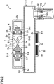
- FIG. 1 illustrates a tip dresser 1 according to an embodiment of the present invention.
- This tip dresser 1 is configured to simultaneously cut the tip ends 10a of a pair of spot-welding electrode tips 10 (see FIG. 4 ) which are fitted into the ends of a shank G1 of a welding gun (not shown) so as to face each other.
- This tip dresser 1 includes a body case 2 surrounding the primary parts of the tip dresser 1, and a cover case 3 configured to prevent chips shaved off during the cutting process from scattering.
- the body case 2 includes a motor housing portion 2a which has a generally circular cylindrical shape extending vertically and which houses a drive motor (not shown) inside and a generally rectangular plate-like protruding portion 2b which protrudes horizontally from a region of the motor housing portion 2a close to the top thereof.
- an upper through hole 2c and a lower through hole 2d are respectively cut through the upper and lower surfaces of a generally center region of the plate-like protruding portion 2b.
- a ringlike output gear 4 is attached rotatably on a vertically extending rotation axis C1 via a pair of (i.e., upper and lower) bearings Be1.
- the output gear 4 is configured to be rotated on the rotation axis C 1 by a drive motor and a gear engaging mechanism (neither is shown).
- a rotary cutter 5 is attached removably with a screw Sc1.
- the rotary cutter 5 includes a metallic holder 51 which forms a generally C shape with a broad width on a plan view and which also defines a vertically short columnar shape.
- the holder 51 has, on one end in the longitudinal direction, a notched recess 52 which is not only open sideward and outward but also extends vertically to be open both upward and downward.
- the notched recess 52 has a generally notched fan shape on a plan view.
- the upper and lower surfaces of the holder 51 respectively have a pair of recessed receivers 53, of which the diameter gradually decreases toward the middle portion of the holder 51.
- These recessed receivers 53 are symmetrical to each other in the rotation axis direction.
- Each of the recessed receivers 53 has a shape corresponding to the curved shape of the tip ends 10a of the electrode tips 10, and is configured to receive the tip end 10a of an associated one of the electrode tips 10 in a state where the center axis of the electrode tip 10 agrees with the rotation axis C 1.
- upper and lower overhanging portions 54 and 55 which overhang outward and sideward.
- upper and lower protrusions 56 and 57 which not only protrude outward and sideward but also extend horizontally (i.e., in a direction which intersects with the longitudinal direction of the holder 51).
- a semicircular recess 56a which is open outward and sideward has been cut through a middle of the upper protrusion 56.
- a portion to be surrounded with the inner peripheral surface of the output gear 4 and the notched recess 52 when the rotary cutter 5 is fitted into the output gear 4 constitutes a through portion 50 according to the present invention.
- the through portion 50 runs through in the rotation axis direction and provides an opening that communicates with the respective recessed receivers 53.
- An inner side surface of the notched recess 52 is provided with a mounting surface 58 which runs in the longitudinal direction of the holder 51.
- the mounting surface 58 has a generally triangular shape on a side view.
- a generally triangular metallic cutting plate 6, which is used to cut the tip ends 10a of the electrode tips 10, and a ringlike metallic breaker Br1 with a tapered outer peripheral surface are fastened with a screw Sc2.
- the upper and lower edges of the cutting plate 6 define a pair of cutting edges 6a.
- the respective cutting edges 6a have a curved shape corresponding to that of the respective recessed receivers 53.
- a disklike cover plate 7 is fixed so as to cover the open end of the upper recessed receiver 53.
- An electrode tip insertion hole 7a of which the shape corresponds to the profile of the electrode tips 10, is cut through a middle portion of the cover plate 7.
- a plurality of air inlet holes 7b are cut side by side through the cover plate 7 at such positions as to face the cutting edge 6a in the rotating direction of the rotary cutter 5.
- the respective air inlet holes 7b form slits that extend radially from the rotation axis C1 of the rotary cutter 5.
- an air discharge unit 11 which is an implementation of the air discharge means and which discharges compressed air toward the surface of the cover plate 7.
- the air discharge unit 11 includes a generally stylus-shaped discharge nozzle 11a which discharges compressed air, a first air tube 11b which guides the compressed air to the discharge nozzle 11 a, and a box-shaped solenoid valve 11c which is connected to a halfway point on the first air tube 11b to control the discharge of the compressed air through the discharge nozzle 11a.
- the tip end of the discharge nozzle 11a is arranged at such a position as to face an outer peripheral portion of the surface of the cover plate 7.
- the cover case 3 has a plate shape which extends horizontally so as to intersect with the direction in which the plate-like protruding portion 2b protrudes.
- One longitudinal end of the cover case 3 forms an inverted V shape on a plan view.
- a communicating hole 3a which communicates with the inner space of the cover case 3 is cut through the upper surface of the cover case 3.
- the cover case 3 is fixed to the lower surface of the plate-like protruding portion 2b so that the communicating hole 3a faces the lower recessed receiver 53. That is to say, the cover case 3 is provided to cover the lower recessed receiver 53 of the rotary cutter 5.
- the tip dresser 1 according to this embodiment of the present invention has its size reduced in its rotation axis direction, because unlike Patent Document 1, there is no need to provide cover cases 3 on both sides of the rotary cutter 5 in its rotation axis direction.
- the lower surface of the cover case 3 and a side surface thereof distant from the motor housing portion 2a are provided with a broad continuously notch 3b (opening) which extends horizontally so as to intersect with the longitudinal direction of the cover case 3.
- the notch 3b is associated with the lower recessed receiver 53.
- the notch 3b is covered with a pair of cover brushes 8 which are arranged side by side in the longitudinal direction of the cover case 3.
- Each of the cover brushes 8 includes a base member 81 which runs along a side edge portion of the notch 3b and a bundle of resin bristles 82 which are transplanted onto the base member 81.
- the two bundles of bristles 82 of the respective base members 81 extend in the longitudinal direction of the cover case 3 to reach an approximately center portion of the notch 3b and eventually cover the notch 3b.
- the respective bundles of bristles 82 are configured to bend upward and close the gap between the side edges of the notch 3b and the outer periphery of the electrode tip 10 as shown in FIG. 4 when the electrode tip 10 is inserted from under, and passed through, the notch 3b.
- a first mounting hole 3c which communicates with the inner space is cut through the lower surface of the cover case 3 on one end of the longitudinal direction thereof
- An air sucking tool 9 air sucking means for sucking air from inside the cover case 3 is connected to the first mounting hole 3c.
- the air sucking tool 9 includes a generally cylindrical tool body 91 which extends vertically.
- the outer peripheral surface of an upper half of the tool body 91 protrudes outward with respect to the outer peripheral surface of a lower half thereof
- a ringlike recessed groove which runs around the center axis of the cylinder is provided halfway on the inner peripheral surface of the tool body 91.
- the rest of the inner peripheral surface of the tool body 91 under the ringlike recessed groove has an inverted tapered shape, of which the diameter gradually increases downward.
- a generally ringlike sucking unit 92 is fitted into the ringlike recessed groove. Inside the sucking unit 92, defined is a ringlike air passage 92a, of which the width gradually decreases downward.
- the upper surface of the cover case 3 at the other end in the longitudinal direction thereof is provided with a second mounting hole 3d which communicates with the inner space.
- One end of a second air tube 93 to introduce compressed air into the space inside the cover case 3 (i.e., compressed air introducing means) is connected to the second mounting hole 3d. That end of the second air tube 93 and the air sucking tool 9 are spaced apart from each other such that the rotation axis C 1 of the rotary cutter 5 is located between them.
- the other end of the second air tube 93 is connected to a halfway point on the first air tube 11b so that part of the compressed air discharged out of the air discharge unit 11 is introduced into the space inside the cover case 3.
- a pair of electrode tips 10 are arranged to face each other so as to vertically interpose the plate-like protruding portion 2b and the cover case 3 between them (i.e., on both sides in the rotation axis direction), and are brought close to each other.
- the tip end 10a of the upper electrode tip 10 passes through the electrode tip insertion hole 7a and is received by the upper recessed receiver 53 and cut by the upper cutting edge 6a.
- the tip end 10a of the lower electrode tip 10 goes through the respective bundles of bristles 82 of the cover brushes 8, passes through the notch 3b and the communicating hole 3a, and is received by the lower recessed receiver 53 and cut by the lower cutting edge 6a.
- compressed air is supplied to the air sucking tool 9 and air discharge unit 11 using an air compressor (not shown). In this manner, the air inside the cover case 3 is sucked by the air sucking tool 9 and evacuated from the cover case 3. In the meantime, the compressed air is also discharged through the discharge nozzle 11a onto the surface of the cover plate 7, and is introduced into the space inside the cover case 3 through the second air tube 93.
- the two electrode tips 10 vertically facing each other are moved to over the plate-like protruding portion 2b and to under the cover case 3, respectively, and the center axis of the respective electrode tips 10 is aligned with the rotation axis C1 of the rotary cutter 5.
- the two electrode tips 10 are brought close to each other. Then, as shown in FIG. 4 , the upper electrode tip 10 passes through the electrode tip insertion hole 7a of the cover plate 7 and is received by the upper recessed receiver 53, and has its tip end 10a cut by the upper cutting edge 6a of the rotary cutter 5 that is rotating.
- the lower electrode tip 10 goes through the respective bundles of bristles 82 of the cover brushes 8, passes through the notch 3b and the communicating hole 3a in this order, and is received by the lower recessed receiver 53 and has its tip end 10a cut by the lower cutting edge 6a of the rotary cutter 5 that is rotating.
- the compressed air discharged through the discharge nozzle 11a is blown against the cutting edges 6a of the cutting plate 6 through the air inlet holes 7b of the cover plate 7 that rotates along with the rotary cutter 5, thus shaking the chips off the cutting edges 6a and preventing the chips from disturbing the work of cutting the tip ends 10a of the electrode tips 10.
- the chips shaved off by the lower electrode tip 10 will fly out through the open end of the lower recessed receiver 53 and go into the cover case 3, and therefore, are prevented from scattering.
- the chips shaved off by the upper electrode tip 10 try to fly out through the open end of the upper recessed receiver 53 but actually collide against, and rebound from, the cover plate 7, and then go into the cover case 3 by passing through the through portion 50 and the communicating hole 3a. In this manner, all of those chips shaved off by cutting the electrode tips 10 are allowed to go into the same cover case 3, and are prevented reliably from scattering.
- the air inlet holes 7b have an elongate shape, which thus allows for preventing the chips shaved off while cutting the electrode tips 10 from abruptly passing through the air inlet holes 7b and scattering around the tip dresser 1.
- the chips moved into the cover case 3 which are accumulated in the vicinity of the air sucking tool 9 are evacuated from the cover case 3 by having the air sucking tool 9 suck air from inside the cover case 3. Meanwhile, the chips accumulated in the vicinity of the second air tube 93 inside the cover case 3 are caused by a turbulent airflow (indicated by XI in FIG. 4 ), produced by the compressed air introduced by the second air tube 93, to float and travel toward the air sucking tool 9. Thereafter, the chips are evacuated by the air sucking tool 9 from the cover case 3. In this manner, all of the chips accumulated inside the cover case 3 are evacuated from the cover case 3 with reliability.
- the tip dresser is configured such that the rotation axis C1 of the rotary cutter 5 extends vertically.
- the tip dresser may also be configured such that the rotation axis C 1 tilts obliquely.
- the air inlet holes 7b have a slit shape.
- the air inlet holes 7b may also have a circular shape or a triangular shape, for example.
- the bristles 82 are made of resin. However, this is only a non-limiting example. Alternatively, the bristles 82 may also be made of a metallic material.
- the present invention is useful as a tip dresser configured to cut the tip ends of spot-welding electrode tips.
Landscapes
- Engineering & Computer Science (AREA)
- Mechanical Engineering (AREA)
- Milling Processes (AREA)
- Physics & Mathematics (AREA)
- Optics & Photonics (AREA)
- Auxiliary Devices For Machine Tools (AREA)
- Sawing (AREA)
Claims (4)
- Dresseur de pointe (1) comprenant :un outil de coupe rotatif (5) configuré pour couper simultanément des extrémités pointes respectives (10a) d'une paire de pointes d'électrodes de soudage par points (10), agencées de manière à se faire face des deux côtés de sa direction d'axe de rotation (C1), par rotation d'une paire de bords de coupe (6a) qui est fournie pour les extrémités pointes respectives (10a) ;un boîtier de corps (2) comprenant une partie en saillie de type plaque (2b), dans lequel la partie en saillie de type plaque est configurée pour loger l'outil de coupe rotatif (5) ; etun boîtier de recouvrement (3) configuré pour empêcher que des copeaux arasés par un travail de coupe avec l'outil de coupe rotatif (5) ne s'éparpillent,dans lequell'outil de coupe rotatif (5) inclut :une paire de récepteurs évidés (53) agencée de manière symétrique dans la direction d'axe de rotation (C1) pour recevoir les extrémités pointes respectives (10a) des pointes d'électrodes (10) de sorte que l'axe central des pointes d'électrodes (10) corresponde à l'axe de rotation (C1) pendant que les récepteurs (53) coupent les extrémités pointes respectives (10a) des pointes d'électrodes (10) ; et une partie traversante (50) se prolongeant dans la direction d'axe de rotation (C1) pour fournir une ouverture qui communique avec les récepteurs évidés respectifs (53),la partie en saillie de type plaque (2b) présente des trous traversants (2c, 2d) associés aux récepteurs évidés respectifs (53) de l'outil de coupe rotatif (5),le boîtier de recouvrement (3) présente une ouverture (3b) et est fixé sur la partie en saillie de type plaque (2b) de manière à recouvrir l'un parmi la paire de récepteurs évidés (53) de sorte que l'ouverture (3b) soit alignée avec le trou traversant (2d) associé avec ledit récepteur évidé (53) de l'outil de coupe rotatif (5) ;caractérisé en ce que le dresseur de pointe inclutune plaque de recouvrement (7) présentant, au niveau de sa partie centrale, un trou d'insertion de pointe d'électrode (7a), dont la forme correspond au profil des pointes d'électrodes (10), la plaque de recouvrement étant fixée à l'autre côté de l'outil de coupe rotatif de manière à recouvrir l'extrémité ouverte de l'autre récepteur évidé (53) de l'outil de coupe rotatif (5) et de manière à être introduite dans le trou traversant (2c) associé à l'autre récepteur évidé (53), la plaque de recouvrement étant configurée pour tourner avec l'outil de coupe rotatif (5).
- Dresseur de pointe selon la revendication 1, dans lequel
un moyen d'évacuation de l'air pour évacuer de l'air comprimé en direction d'une surface de la plaque de recouvrement est agencé à proximité de l'autre côté de la plaque de recouvrement à l'opposé de l'outil de coupe rotatif, et
une pluralité de trous d'admission d'air sont formés côte à côte à travers la plaque de recouvrement au niveau de positions telles qu'elle fait face au bord de coupe dans une direction dans laquelle l'outil de coupe rotatif tourne. - Dresseur de pointe selon la revendication 2, dans lequel
les trous d'admission d'air forment des fentes qui s'étendent radialement depuis l'axe de rotation de l'outil de coupe rotatif. - Dresseur de pointe selon l'une quelconque des revendications 1 à 3, dans lequel
un moyen d'aspiration d'air pour aspirer de l'air depuis l'intérieur du boîtier de recouvrement et un moyen d'introduction d'air comprimé pour introduire de l'air comprimé à l'intérieur du boîtier de recouvrement sont reliés au boîtier de recouvrement, le moyen d'introduction d'air comprimé et le moyen d'aspiration d'air étant espacés l'un de l'autre de sorte que l'axe de rotation de l'outil de coupe rotatif soit situé entre ces deux moyens.
Applications Claiming Priority (1)
| Application Number | Priority Date | Filing Date | Title |
|---|---|---|---|
| PCT/JP2015/001644 WO2016151623A1 (fr) | 2015-03-23 | 2015-03-23 | Dresseur de pointe |
Publications (3)
| Publication Number | Publication Date |
|---|---|
| EP3093094A1 EP3093094A1 (fr) | 2016-11-16 |
| EP3093094A4 EP3093094A4 (fr) | 2016-11-16 |
| EP3093094B1 true EP3093094B1 (fr) | 2017-08-02 |
Family
ID=56976418
Family Applications (1)
| Application Number | Title | Priority Date | Filing Date |
|---|---|---|---|
| EP15784920.9A Active EP3093094B1 (fr) | 2015-03-23 | 2015-03-23 | Dresseur de pointe |
Country Status (7)
| Country | Link |
|---|---|
| US (1) | US9707639B2 (fr) |
| EP (1) | EP3093094B1 (fr) |
| JP (1) | JP6368852B2 (fr) |
| KR (1) | KR101768791B1 (fr) |
| CN (1) | CN106170364B (fr) |
| BR (1) | BR112015029600B1 (fr) |
| WO (1) | WO2016151623A1 (fr) |
Families Citing this family (12)
| Publication number | Priority date | Publication date | Assignee | Title |
|---|---|---|---|---|
| JP5951137B1 (ja) * | 2014-09-30 | 2016-07-13 | 株式会社キョクトー | チップドレス用切削カッター |
| JP7007701B2 (ja) | 2017-05-11 | 2022-01-25 | 株式会社キョクトー | 切粉回収装置 |
| CN107186484B (zh) * | 2017-06-28 | 2018-11-09 | 嘉兴顾翔制冷设备有限公司 | 一种新材料圆边修整设备 |
| JP6937020B2 (ja) | 2017-11-20 | 2021-09-22 | 株式会社キョクトー | 切粉飛散防止カバー |
| KR101848304B1 (ko) * | 2017-11-22 | 2018-04-12 | 주식회사 나우정공 | 팁 드레서용 임펠라 플레이트 |
| JP7120603B2 (ja) * | 2018-04-16 | 2022-08-17 | 株式会社キョクトー | チップドレス用切削カッター |
| EP3782761A4 (fr) * | 2018-04-19 | 2022-01-19 | Kyokutoh Co., Ltd. | Dresseur de pointe |
| DE112020002951T5 (de) | 2019-06-18 | 2022-03-17 | Magna International Inc. | Spitzenbearbeitungsinstallationssystem und Verfahren |
| EP3766621A1 (fr) * | 2019-07-15 | 2021-01-20 | Lutz Precision, K.S. | Dispositif permettant de dévisser et de détacher un capuchon d'électrode d'un dispositif de réception des capuchons d'électrode et dispositif de détachement |
| JP7333605B2 (ja) * | 2019-11-18 | 2023-08-25 | 株式会社キョクトー | チップドレッサー |
| JP7350261B2 (ja) | 2020-02-27 | 2023-09-26 | 株式会社キョクトー | エアブローノズル及びエアブローノズル付きチップドレッサー |
| CN116140921B (zh) * | 2023-03-24 | 2025-04-11 | 扬帆研华(天津)科技发展有限公司 | 一种用于电阻点焊电极的自动修磨器 |
Citations (1)
| Publication number | Priority date | Publication date | Assignee | Title |
|---|---|---|---|---|
| WO1997044153A1 (fr) * | 1996-05-21 | 1997-11-27 | Lutz Peter Stephan | Systeme de fraisage et procede pour fraiser la zone de soudage d'electrodes de soudage par points |
Family Cites Families (15)
| Publication number | Priority date | Publication date | Assignee | Title |
|---|---|---|---|---|
| JP3827184B2 (ja) * | 1997-12-19 | 2006-09-27 | 本田技研工業株式会社 | ドーム形電極チップの整形方法 |
| US6106203A (en) * | 1998-03-18 | 2000-08-22 | Semtorq, Inc. | Electrode tip dresser with vacuum |
| JP4812975B2 (ja) * | 2000-09-07 | 2011-11-09 | 富士重工業株式会社 | 電極チップ整形装置 |
| JP2002361193A (ja) * | 2001-06-06 | 2002-12-17 | Kyokutoh Co Ltd | ドレッサー用吸引機 |
| US20030013395A1 (en) * | 2001-06-20 | 2003-01-16 | Fuji Jukogyo Kabushiki Kaisha | Chip collecting apparatus for tip dresser |
| JP4772221B2 (ja) * | 2001-06-27 | 2011-09-14 | 富士重工業株式会社 | チップドレッサ用切粉回収装置 |
| JP4772219B2 (ja) * | 2001-06-27 | 2011-09-14 | 富士重工業株式会社 | チップドレッサ用切粉回収装置 |
| JP3983021B2 (ja) * | 2001-09-06 | 2007-09-26 | 本田技研工業株式会社 | チップドレッサの切粉排出装置及び排出方法 |
| JP4308514B2 (ja) | 2002-12-24 | 2009-08-05 | Obara株式会社 | チップドレッサにおける切粉回収装置 |
| JP4399435B2 (ja) * | 2005-09-01 | 2010-01-13 | 株式会社キョクトー | チップ成形機 |
| EP1797986A1 (fr) * | 2005-12-19 | 2007-06-20 | INPRO Innovationsgesellschaft für fortgeschrittene Produktionssysteme in der Fahrzeugindustrie mbH | Dispositif de fraisage, notamment pour le dressage des capuchons d'électrodes et pointes d'électrode de soudage par points de cuivre |
| JP5219704B2 (ja) * | 2008-09-09 | 2013-06-26 | 新光機器株式会社 | チップドレッサー装置 |
| US8388283B2 (en) * | 2008-12-08 | 2013-03-05 | GM Global Technology Operations LLC | Chip catcher for weld tip dresser |
| EP2570199B1 (fr) * | 2011-09-13 | 2017-05-10 | Lutz Precision, K.S. | Dispositif de fraisage de la zone de soudage d'électrodes soudées par points comprenant des moyens de nettoyage |
| CN105636660A (zh) * | 2014-06-11 | 2016-06-01 | 极动焊接机械有限公司 | 切屑回收装置 |
-
2015
- 2015-03-23 EP EP15784920.9A patent/EP3093094B1/fr active Active
- 2015-03-23 JP JP2017507104A patent/JP6368852B2/ja active Active
- 2015-03-23 CN CN201580000729.1A patent/CN106170364B/zh active Active
- 2015-03-23 BR BR112015029600-9A patent/BR112015029600B1/pt active IP Right Grant
- 2015-03-23 WO PCT/JP2015/001644 patent/WO2016151623A1/fr not_active Ceased
- 2015-03-23 KR KR1020157031356A patent/KR101768791B1/ko active Active
- 2015-11-03 US US14/931,372 patent/US9707639B2/en active Active
Patent Citations (1)
| Publication number | Priority date | Publication date | Assignee | Title |
|---|---|---|---|---|
| WO1997044153A1 (fr) * | 1996-05-21 | 1997-11-27 | Lutz Peter Stephan | Systeme de fraisage et procede pour fraiser la zone de soudage d'electrodes de soudage par points |
Also Published As
| Publication number | Publication date |
|---|---|
| US9707639B2 (en) | 2017-07-18 |
| JP6368852B2 (ja) | 2018-08-01 |
| BR112015029600B1 (pt) | 2021-04-06 |
| JPWO2016151623A1 (ja) | 2017-05-25 |
| EP3093094A1 (fr) | 2016-11-16 |
| US20160279733A1 (en) | 2016-09-29 |
| BR112015029600A2 (pt) | 2017-07-25 |
| WO2016151623A1 (fr) | 2016-09-29 |
| CN106170364B (zh) | 2019-03-19 |
| KR20160128199A (ko) | 2016-11-07 |
| CN106170364A (zh) | 2016-11-30 |
| KR101768791B1 (ko) | 2017-08-17 |
| EP3093094A4 (fr) | 2016-11-16 |
Similar Documents
| Publication | Publication Date | Title |
|---|---|---|
| EP3093094B1 (fr) | Dresseur de pointe | |
| US8480337B2 (en) | Drill with cutting inserts | |
| CN108367379A (zh) | 电极头修磨用切削刀和电极头修磨器 | |
| KR101731197B1 (ko) | 팁 드레서용 절삭 커터 | |
| US5988956A (en) | Hole cutter | |
| KR102220017B1 (ko) | 팁 드레서 | |
| EP3608053A1 (fr) | Dispositif de collecte de puces | |
| KR20100035993A (ko) | 팁 드레서용 집진 커버 | |
| US12420352B2 (en) | Tip dresser | |
| EP3778093B1 (fr) | Outil de coupe d'usinage de dressage de pointe | |
| US20200238464A1 (en) | Chip-scattering prevention cover | |
| KR200348659Y1 (ko) | 용접 팁 드레서의 커터조립체 | |
| JP4949724B2 (ja) | 木材のプレカット設備用集塵装置 | |
| JP4552602B2 (ja) | 切削工具 | |
| KR102240398B1 (ko) | 용접 팁 드레서용 팁 가이드 | |
| KR101469300B1 (ko) | 절단기를 이용한 고정 홀의 형성방법 | |
| JP2006212685A (ja) | ハンドドレッサー |
Legal Events
| Date | Code | Title | Description |
|---|---|---|---|
| PUAI | Public reference made under article 153(3) epc to a published international application that has entered the european phase |
Free format text: ORIGINAL CODE: 0009012 |
|
| 17P | Request for examination filed |
Effective date: 20151104 |
|
| A4 | Supplementary search report drawn up and despatched |
Effective date: 20160425 |
|
| AK | Designated contracting states |
Kind code of ref document: A1 Designated state(s): AL AT BE BG CH CY CZ DE DK EE ES FI FR GB GR HR HU IE IS IT LI LT LU LV MC MK MT NL NO PL PT RO RS SE SI SK SM TR |
|
| AX | Request for extension of the european patent |
Extension state: BA ME |
|
| GRAP | Despatch of communication of intention to grant a patent |
Free format text: ORIGINAL CODE: EPIDOSNIGR1 |
|
| RIC1 | Information provided on ipc code assigned before grant |
Ipc: B23B 5/16 20060101ALI20170210BHEP Ipc: B23K 11/30 20060101AFI20170210BHEP |
|
| INTG | Intention to grant announced |
Effective date: 20170301 |
|
| GRAS | Grant fee paid |
Free format text: ORIGINAL CODE: EPIDOSNIGR3 |
|
| GRAA | (expected) grant |
Free format text: ORIGINAL CODE: 0009210 |
|
| AK | Designated contracting states |
Kind code of ref document: B1 Designated state(s): AL AT BE BG CH CY CZ DE DK EE ES FI FR GB GR HR HU IE IS IT LI LT LU LV MC MK MT NL NO PL PT RO RS SE SI SK SM TR |
|
| DAV | Request for validation of the european patent (deleted) | ||
| DAX | Request for extension of the european patent (deleted) | ||
| REG | Reference to a national code |
Ref country code: CH Ref legal event code: EP Ref country code: AT Ref legal event code: REF Ref document number: 913914 Country of ref document: AT Kind code of ref document: T Effective date: 20170815 |
|
| REG | Reference to a national code |
Ref country code: IE Ref legal event code: FG4D |
|
| REG | Reference to a national code |
Ref country code: DE Ref legal event code: R096 Ref document number: 602015003912 Country of ref document: DE |
|
| REG | Reference to a national code |
Ref country code: NL Ref legal event code: MP Effective date: 20170802 |
|
| REG | Reference to a national code |
Ref country code: AT Ref legal event code: MK05 Ref document number: 913914 Country of ref document: AT Kind code of ref document: T Effective date: 20170802 |
|
| REG | Reference to a national code |
Ref country code: LT Ref legal event code: MG4D |
|
| PG25 | Lapsed in a contracting state [announced via postgrant information from national office to epo] |
Ref country code: SE Free format text: LAPSE BECAUSE OF FAILURE TO SUBMIT A TRANSLATION OF THE DESCRIPTION OR TO PAY THE FEE WITHIN THE PRESCRIBED TIME-LIMIT Effective date: 20170802 Ref country code: NO Free format text: LAPSE BECAUSE OF FAILURE TO SUBMIT A TRANSLATION OF THE DESCRIPTION OR TO PAY THE FEE WITHIN THE PRESCRIBED TIME-LIMIT Effective date: 20171102 Ref country code: NL Free format text: LAPSE BECAUSE OF FAILURE TO SUBMIT A TRANSLATION OF THE DESCRIPTION OR TO PAY THE FEE WITHIN THE PRESCRIBED TIME-LIMIT Effective date: 20170802 Ref country code: HR Free format text: LAPSE BECAUSE OF FAILURE TO SUBMIT A TRANSLATION OF THE DESCRIPTION OR TO PAY THE FEE WITHIN THE PRESCRIBED TIME-LIMIT Effective date: 20170802 Ref country code: LT Free format text: LAPSE BECAUSE OF FAILURE TO SUBMIT A TRANSLATION OF THE DESCRIPTION OR TO PAY THE FEE WITHIN THE PRESCRIBED TIME-LIMIT Effective date: 20170802 Ref country code: AT Free format text: LAPSE BECAUSE OF FAILURE TO SUBMIT A TRANSLATION OF THE DESCRIPTION OR TO PAY THE FEE WITHIN THE PRESCRIBED TIME-LIMIT Effective date: 20170802 Ref country code: FI Free format text: LAPSE BECAUSE OF FAILURE TO SUBMIT A TRANSLATION OF THE DESCRIPTION OR TO PAY THE FEE WITHIN THE PRESCRIBED TIME-LIMIT Effective date: 20170802 |
|
| PG25 | Lapsed in a contracting state [announced via postgrant information from national office to epo] |
Ref country code: LV Free format text: LAPSE BECAUSE OF FAILURE TO SUBMIT A TRANSLATION OF THE DESCRIPTION OR TO PAY THE FEE WITHIN THE PRESCRIBED TIME-LIMIT Effective date: 20170802 Ref country code: RS Free format text: LAPSE BECAUSE OF FAILURE TO SUBMIT A TRANSLATION OF THE DESCRIPTION OR TO PAY THE FEE WITHIN THE PRESCRIBED TIME-LIMIT Effective date: 20170802 Ref country code: ES Free format text: LAPSE BECAUSE OF FAILURE TO SUBMIT A TRANSLATION OF THE DESCRIPTION OR TO PAY THE FEE WITHIN THE PRESCRIBED TIME-LIMIT Effective date: 20170802 Ref country code: PL Free format text: LAPSE BECAUSE OF FAILURE TO SUBMIT A TRANSLATION OF THE DESCRIPTION OR TO PAY THE FEE WITHIN THE PRESCRIBED TIME-LIMIT Effective date: 20170802 Ref country code: BG Free format text: LAPSE BECAUSE OF FAILURE TO SUBMIT A TRANSLATION OF THE DESCRIPTION OR TO PAY THE FEE WITHIN THE PRESCRIBED TIME-LIMIT Effective date: 20171102 Ref country code: GR Free format text: LAPSE BECAUSE OF FAILURE TO SUBMIT A TRANSLATION OF THE DESCRIPTION OR TO PAY THE FEE WITHIN THE PRESCRIBED TIME-LIMIT Effective date: 20171103 Ref country code: IS Free format text: LAPSE BECAUSE OF FAILURE TO SUBMIT A TRANSLATION OF THE DESCRIPTION OR TO PAY THE FEE WITHIN THE PRESCRIBED TIME-LIMIT Effective date: 20171202 |
|
| REG | Reference to a national code |
Ref country code: FR Ref legal event code: PLFP Year of fee payment: 4 |
|
| PG25 | Lapsed in a contracting state [announced via postgrant information from national office to epo] |
Ref country code: CZ Free format text: LAPSE BECAUSE OF FAILURE TO SUBMIT A TRANSLATION OF THE DESCRIPTION OR TO PAY THE FEE WITHIN THE PRESCRIBED TIME-LIMIT Effective date: 20170802 Ref country code: DK Free format text: LAPSE BECAUSE OF FAILURE TO SUBMIT A TRANSLATION OF THE DESCRIPTION OR TO PAY THE FEE WITHIN THE PRESCRIBED TIME-LIMIT Effective date: 20170802 |
|
| REG | Reference to a national code |
Ref country code: DE Ref legal event code: R097 Ref document number: 602015003912 Country of ref document: DE |
|
| PG25 | Lapsed in a contracting state [announced via postgrant information from national office to epo] |
Ref country code: SM Free format text: LAPSE BECAUSE OF FAILURE TO SUBMIT A TRANSLATION OF THE DESCRIPTION OR TO PAY THE FEE WITHIN THE PRESCRIBED TIME-LIMIT Effective date: 20170802 Ref country code: SK Free format text: LAPSE BECAUSE OF FAILURE TO SUBMIT A TRANSLATION OF THE DESCRIPTION OR TO PAY THE FEE WITHIN THE PRESCRIBED TIME-LIMIT Effective date: 20170802 Ref country code: EE Free format text: LAPSE BECAUSE OF FAILURE TO SUBMIT A TRANSLATION OF THE DESCRIPTION OR TO PAY THE FEE WITHIN THE PRESCRIBED TIME-LIMIT Effective date: 20170802 |
|
| PLBE | No opposition filed within time limit |
Free format text: ORIGINAL CODE: 0009261 |
|
| STAA | Information on the status of an ep patent application or granted ep patent |
Free format text: STATUS: NO OPPOSITION FILED WITHIN TIME LIMIT |
|
| 26N | No opposition filed |
Effective date: 20180503 |
|
| PG25 | Lapsed in a contracting state [announced via postgrant information from national office to epo] |
Ref country code: SI Free format text: LAPSE BECAUSE OF FAILURE TO SUBMIT A TRANSLATION OF THE DESCRIPTION OR TO PAY THE FEE WITHIN THE PRESCRIBED TIME-LIMIT Effective date: 20170802 |
|
| REG | Reference to a national code |
Ref country code: CH Ref legal event code: PL |
|
| PG25 | Lapsed in a contracting state [announced via postgrant information from national office to epo] |
Ref country code: MC Free format text: LAPSE BECAUSE OF FAILURE TO SUBMIT A TRANSLATION OF THE DESCRIPTION OR TO PAY THE FEE WITHIN THE PRESCRIBED TIME-LIMIT Effective date: 20170802 |
|
| REG | Reference to a national code |
Ref country code: BE Ref legal event code: MM Effective date: 20180331 |
|
| REG | Reference to a national code |
Ref country code: IE Ref legal event code: MM4A |
|
| PG25 | Lapsed in a contracting state [announced via postgrant information from national office to epo] |
Ref country code: LU Free format text: LAPSE BECAUSE OF NON-PAYMENT OF DUE FEES Effective date: 20180323 |
|
| PG25 | Lapsed in a contracting state [announced via postgrant information from national office to epo] |
Ref country code: IE Free format text: LAPSE BECAUSE OF NON-PAYMENT OF DUE FEES Effective date: 20180323 |
|
| PG25 | Lapsed in a contracting state [announced via postgrant information from national office to epo] |
Ref country code: LI Free format text: LAPSE BECAUSE OF NON-PAYMENT OF DUE FEES Effective date: 20180331 Ref country code: BE Free format text: LAPSE BECAUSE OF NON-PAYMENT OF DUE FEES Effective date: 20180331 Ref country code: CH Free format text: LAPSE BECAUSE OF NON-PAYMENT OF DUE FEES Effective date: 20180331 |
|
| PG25 | Lapsed in a contracting state [announced via postgrant information from national office to epo] |
Ref country code: MT Free format text: LAPSE BECAUSE OF NON-PAYMENT OF DUE FEES Effective date: 20180323 |
|
| PG25 | Lapsed in a contracting state [announced via postgrant information from national office to epo] |
Ref country code: TR Free format text: LAPSE BECAUSE OF FAILURE TO SUBMIT A TRANSLATION OF THE DESCRIPTION OR TO PAY THE FEE WITHIN THE PRESCRIBED TIME-LIMIT Effective date: 20170802 |
|
| PG25 | Lapsed in a contracting state [announced via postgrant information from national office to epo] |
Ref country code: PT Free format text: LAPSE BECAUSE OF FAILURE TO SUBMIT A TRANSLATION OF THE DESCRIPTION OR TO PAY THE FEE WITHIN THE PRESCRIBED TIME-LIMIT Effective date: 20170802 |
|
| PG25 | Lapsed in a contracting state [announced via postgrant information from national office to epo] |
Ref country code: HU Free format text: LAPSE BECAUSE OF FAILURE TO SUBMIT A TRANSLATION OF THE DESCRIPTION OR TO PAY THE FEE WITHIN THE PRESCRIBED TIME-LIMIT; INVALID AB INITIO Effective date: 20150323 Ref country code: RO Free format text: LAPSE BECAUSE OF FAILURE TO SUBMIT A TRANSLATION OF THE DESCRIPTION OR TO PAY THE FEE WITHIN THE PRESCRIBED TIME-LIMIT Effective date: 20170802 Ref country code: MK Free format text: LAPSE BECAUSE OF NON-PAYMENT OF DUE FEES Effective date: 20170802 Ref country code: CY Free format text: LAPSE BECAUSE OF FAILURE TO SUBMIT A TRANSLATION OF THE DESCRIPTION OR TO PAY THE FEE WITHIN THE PRESCRIBED TIME-LIMIT Effective date: 20170802 |
|
| PG25 | Lapsed in a contracting state [announced via postgrant information from national office to epo] |
Ref country code: AL Free format text: LAPSE BECAUSE OF FAILURE TO SUBMIT A TRANSLATION OF THE DESCRIPTION OR TO PAY THE FEE WITHIN THE PRESCRIBED TIME-LIMIT Effective date: 20170802 |
|
| PGFP | Annual fee paid to national office [announced via postgrant information from national office to epo] |
Ref country code: GB Payment date: 20260324 Year of fee payment: 12 |
|
| PGFP | Annual fee paid to national office [announced via postgrant information from national office to epo] |
Ref country code: DE Payment date: 20260319 Year of fee payment: 12 |
|
| PGFP | Annual fee paid to national office [announced via postgrant information from national office to epo] |
Ref country code: IT Payment date: 20260324 Year of fee payment: 12 |
|
| PGFP | Annual fee paid to national office [announced via postgrant information from national office to epo] |
Ref country code: FR Payment date: 20260320 Year of fee payment: 12 |