EP3093096B1 - Appareil de soudage au laser et procédé de soudage au laser - Google Patents
Appareil de soudage au laser et procédé de soudage au laser Download PDFInfo
- Publication number
- EP3093096B1 EP3093096B1 EP14878251.9A EP14878251A EP3093096B1 EP 3093096 B1 EP3093096 B1 EP 3093096B1 EP 14878251 A EP14878251 A EP 14878251A EP 3093096 B1 EP3093096 B1 EP 3093096B1
- Authority
- EP
- European Patent Office
- Prior art keywords
- laser
- laser beam
- workpiece
- output
- region
- Prior art date
- Legal status (The legal status is an assumption and is not a legal conclusion. Google has not performed a legal analysis and makes no representation as to the accuracy of the status listed.)
- Active
Links
Images




Classifications
-
- B—PERFORMING OPERATIONS; TRANSPORTING
- B23—MACHINE TOOLS; METAL-WORKING NOT OTHERWISE PROVIDED FOR
- B23K—SOLDERING OR UNSOLDERING; WELDING; CLADDING OR PLATING BY SOLDERING OR WELDING; CUTTING BY APPLYING HEAT LOCALLY, e.g. FLAME CUTTING; WORKING BY LASER BEAM
- B23K26/00—Working by laser beam, e.g. welding, cutting or boring
- B23K26/20—Bonding
- B23K26/32—Bonding taking account of the properties of the material involved
- B23K26/322—Bonding taking account of the properties of the material involved involving coated metal parts
-
- B—PERFORMING OPERATIONS; TRANSPORTING
- B23—MACHINE TOOLS; METAL-WORKING NOT OTHERWISE PROVIDED FOR
- B23K—SOLDERING OR UNSOLDERING; WELDING; CLADDING OR PLATING BY SOLDERING OR WELDING; CUTTING BY APPLYING HEAT LOCALLY, e.g. FLAME CUTTING; WORKING BY LASER BEAM
- B23K26/00—Working by laser beam, e.g. welding, cutting or boring
- B23K26/0006—Working by laser beam, e.g. welding, cutting or boring taking account of the properties of the material involved
-
- B—PERFORMING OPERATIONS; TRANSPORTING
- B23—MACHINE TOOLS; METAL-WORKING NOT OTHERWISE PROVIDED FOR
- B23K—SOLDERING OR UNSOLDERING; WELDING; CLADDING OR PLATING BY SOLDERING OR WELDING; CUTTING BY APPLYING HEAT LOCALLY, e.g. FLAME CUTTING; WORKING BY LASER BEAM
- B23K26/00—Working by laser beam, e.g. welding, cutting or boring
- B23K26/08—Devices involving relative movement between laser beam and workpiece
- B23K26/082—Scanning systems, i.e. devices involving movement of the laser beam relative to the laser head
-
- B—PERFORMING OPERATIONS; TRANSPORTING
- B23—MACHINE TOOLS; METAL-WORKING NOT OTHERWISE PROVIDED FOR
- B23K—SOLDERING OR UNSOLDERING; WELDING; CLADDING OR PLATING BY SOLDERING OR WELDING; CUTTING BY APPLYING HEAT LOCALLY, e.g. FLAME CUTTING; WORKING BY LASER BEAM
- B23K26/00—Working by laser beam, e.g. welding, cutting or boring
- B23K26/20—Bonding
- B23K26/21—Bonding by welding
- B23K26/22—Spot welding
-
- B—PERFORMING OPERATIONS; TRANSPORTING
- B23—MACHINE TOOLS; METAL-WORKING NOT OTHERWISE PROVIDED FOR
- B23K—SOLDERING OR UNSOLDERING; WELDING; CLADDING OR PLATING BY SOLDERING OR WELDING; CUTTING BY APPLYING HEAT LOCALLY, e.g. FLAME CUTTING; WORKING BY LASER BEAM
- B23K26/00—Working by laser beam, e.g. welding, cutting or boring
- B23K26/20—Bonding
- B23K26/21—Bonding by welding
- B23K26/24—Seam welding
- B23K26/244—Overlap seam welding
-
- B—PERFORMING OPERATIONS; TRANSPORTING
- B25—HAND TOOLS; PORTABLE POWER-DRIVEN TOOLS; MANIPULATORS
- B25J—MANIPULATORS; CHAMBERS PROVIDED WITH MANIPULATION DEVICES
- B25J11/00—Manipulators not otherwise provided for
- B25J11/005—Manipulators for mechanical processing tasks
-
- B—PERFORMING OPERATIONS; TRANSPORTING
- B23—MACHINE TOOLS; METAL-WORKING NOT OTHERWISE PROVIDED FOR
- B23K—SOLDERING OR UNSOLDERING; WELDING; CLADDING OR PLATING BY SOLDERING OR WELDING; CUTTING BY APPLYING HEAT LOCALLY, e.g. FLAME CUTTING; WORKING BY LASER BEAM
- B23K2101/00—Articles made by soldering, welding or cutting
- B23K2101/006—Vehicles
-
- B—PERFORMING OPERATIONS; TRANSPORTING
- B23—MACHINE TOOLS; METAL-WORKING NOT OTHERWISE PROVIDED FOR
- B23K—SOLDERING OR UNSOLDERING; WELDING; CLADDING OR PLATING BY SOLDERING OR WELDING; CUTTING BY APPLYING HEAT LOCALLY, e.g. FLAME CUTTING; WORKING BY LASER BEAM
- B23K2101/00—Articles made by soldering, welding or cutting
- B23K2101/34—Coated articles ; Surface treated articles
-
- B—PERFORMING OPERATIONS; TRANSPORTING
- B23—MACHINE TOOLS; METAL-WORKING NOT OTHERWISE PROVIDED FOR
- B23K—SOLDERING OR UNSOLDERING; WELDING; CLADDING OR PLATING BY SOLDERING OR WELDING; CUTTING BY APPLYING HEAT LOCALLY, e.g. FLAME CUTTING; WORKING BY LASER BEAM
- B23K2103/00—Materials to be soldered, welded or cut
- B23K2103/02—Iron or ferrous alloys
- B23K2103/04—Steel or steel alloys
-
- B—PERFORMING OPERATIONS; TRANSPORTING
- B23—MACHINE TOOLS; METAL-WORKING NOT OTHERWISE PROVIDED FOR
- B23K—SOLDERING OR UNSOLDERING; WELDING; CLADDING OR PLATING BY SOLDERING OR WELDING; CUTTING BY APPLYING HEAT LOCALLY, e.g. FLAME CUTTING; WORKING BY LASER BEAM
- B23K2103/00—Materials to be soldered, welded or cut
- B23K2103/08—Non-ferrous metals or alloys
-
- G—PHYSICS
- G05—CONTROLLING; REGULATING
- G05B—CONTROL OR REGULATING SYSTEMS IN GENERAL; FUNCTIONAL ELEMENTS OF SUCH SYSTEMS; MONITORING OR TESTING ARRANGEMENTS FOR SUCH SYSTEMS OR ELEMENTS
- G05B2219/00—Program-control systems
- G05B2219/30—Nc systems
- G05B2219/45—Nc applications
- G05B2219/45135—Welding
Definitions
- the present disclosure relates to a laser welding method and a laser welding device that stack surface-treated members such as galvanized steel plates or the like on each other and then weld the stacked members by using a laser. More specifically, the present disclosure relates to laser welding that is effective in reducing formation of blowholes and pits.
- Galvanized steel plates have superior resistance to rust and corrosion. For that reason, recently, galvanized steel plates have been used for automotive parts, architectural steel frames, and other members. Such galvanized steel plates are welded in accordance with their applications.
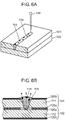
- FIG. 6A and FIG. 7A are perspective views to explain a conventional laser welding method.
- FIG. 6B is a cross section view related to FIG. 6A , which explains the conventional laser welding method;
- FIG. 7B is a cross section view related to FIG. 7A , which explains the conventional laser welding method.
- Anticorrosive steel plate 101 and anticorrosive steel plate 102 are stacked on each other.
- Anticorrosive steel plate 101 is steel plate 111 in which galvanized layer 120a is formed on a front surface and galvanized layer 120b is formed on a rear surface.
- Anticorrosive steel plate 102 is steel plate 112 in which galvanized layer 120a is formed on a front surface and galvanized layer 120b is formed on a rear surface.
- Anticorrosive steel plate 101 and anticorrosive steel plate 102 are stacked on each other in such a manner that their galvanized layers 120a are in contact with each other.
- stacked anticorrosive steel plates 101, 102 are irradiated with laser beam 100 as a first laser irradiation.
- a heat input quantity of laser beam 100 is set such that laser beam 100 reaches galvanized layers 120a of anticorrosive steel plate 101 and anticorrosive steel plate 102 but does not penetrate anticorrosive steel plate 102.
- anticorrosive steel plates 101, 102 are irradiated with laser beam 100 as a second laser irradiation.
- the heat input quantity of laser beam 100 is set such that laser beam 100 reliably reaches anticorrosive steel plate 102, finishing welding. Therefore, the energy of laser beam 100 for the second laser irradiation is set to be higher than the energy of laser beam 100 for the first laser irradiation. Further, the energy of laser beam 100 for the second laser irradiation is required to be set to be substantially as high as the energy of a laser beam used for typical laser welding. Moreover, laser beam 100 for the second laser irradiation may pass through the same path as laser beam 100 for the first laser irradiation.
- PTL2 discloses all of the preamble of claims 1 and 11.
- the first laser irradiation may fail to sufficiently discharge a zinc vapor, and the second laser irradiation may further generate a zinc vapor due to heat transfer, in which case porosities might be created.
- the present disclosure provides a laser welding method and a laser welding device that are capable of reducing formation of pores by sufficiently discharging a zinc vapor with first laser irradiation and by performing main welding with second laser irradiation.
- a laser welding method of the present disclosure which addresses the above problems, is defined in claim 1 and includes a first step, a second step, and a third step.
- a first workpiece and a second workpiece are stacked on each other.
- Each of the first workpiece and the second workpiece has a surface coated with a first material and is made of a second material, which is different from the first material.
- a first region in which the first workpiece and the second workpiece are stacked on each other is irradiated with a laser beam so that the laser beam penetrates both the first workpiece and the second workpiece.
- a second region including the first region is irradiated with the laser beam in a spiral fashion.
- a laser welding device of the present disclosure is defined in claim 11 and includes a laser oscillator, a laser head, a robot, and a control unit.
- the laser oscillator outputs a laser beam.
- the laser head irradiates a first workpiece and a second workpiece with the laser beam.
- Each of the first workpiece and the second workpiece has a surface coated with a first material and is made of a second material, which is different from the first material.
- the laser head is provided in the robot.
- the control unit controls an output of the laser oscillator, an operation of the laser head, and an operation of the robot.
- the laser head irradiates, with a laser beam, a first region in which the first workpiece and the second workpiece are stacked on each other so that the laser beam penetrates both the first workpiece and the second workpiece.
- the laser head irradiates a second region including the first region with the laser beam in a spiral fashion.
- first laser irradiation sufficiently discharges a zinc vapor
- second laser irradiation performs main welding.
- This two-time laser irradiation successfully reduces formation of pores and an influence of the zinc vapor during the main welding. Therefore, it is possible to control formation of pores in the interior and surface of a weld bead.
- FIG. 1 illustrates a schematic configuration of a laser welding device in this exemplary embodiment.
- FIG. 2A illustrates steps of a laser welding method in this exemplary embodiment.
- FIG. 2B is a graph indicating laser output power in the laser welding method in this exemplary embodiment.
- FIG. 2C is a graph indicating laser output power in another laser welding method in this exemplary embodiment.
- the horizontal axis represents a time t and the vertical axis represents laser output power LW.
- a laser welding device in this exemplary embodiment includes laser oscillator 1, robot 2, controller 3 (control unit), laser irradiation head 7 (laser head), and optical fiber 8.
- Laser oscillator 1 is connected to controller 3 and to a first end of optical fiber 8. Laser oscillator 1 outputs a laser beam, and then the laser beam enters optical fiber 8.
- Robot 2 is connected to controller 3 and is provided with laser irradiation head 7 at its end.
- Controller 3 has welding condition setting section 4, operation control section 5, and laser output control section 6.
- Welding condition setting section 4 sets conditions for laser welding (an output of the laser beam and a movement of the laser beam, such as a welding speed and a path of the laser beam).
- Operation control section 5 controls an operation of robot 2 and an operation of laser irradiation head 7, based on an instruction from welding condition setting section 4 or an operation program taught in advance.
- Laser output control section 6 controls an output of a laser beam oscillated by laser oscillator 1, based on an instruction from welding condition setting section 4.
- Laser irradiation head 7 is connected to a second end of optical fiber 8 and irradiates workpiece 9 (first workpiece and second workpiece) with laser beam 10.
- Laser irradiation head 7 includes a galvanometer mirror, a collimator lens, and a condenser lens, as exemplary components.
- Optical fiber 8 is connected between laser oscillator 1 and laser irradiation head 7. The laser beam output from laser oscillator 1 is transmitted to laser irradiation head 7 through optical fiber 8.
- Workpiece 9 includes two stacked, galvanized steel plates. Each of the galvanized steel plates has a surface coated with zinc (first material) and is made of iron (second material). When laser oscillator 1 oscillates laser beam 10, laser beam 10 travels in optical fiber 8 and is collected by laser irradiation head 7. As a result, workpiece 9 is irradiated with laser beam 10.
- a first one of two galvanized steel plates and a second one are stacked on each other in accordance with a relation of a welding location (first step).
- the two galvanized steel plates may be stacked by a transfer device, which is independent of the above laser welding device, or by an operator.
- workpiece 9 in which the two galvanized steel plates, each of which has a surface coated with zinc 11 (first material) and is made of iron 12 (second material), are stacked on each other is fabricated.
- the workpiece to be welded with laser by a laser welding method and a laser welding device of the present disclosure is not limited to galvanized steel plates.
- any other workpieces in which the boiling point of a material for the surfaces (zinc contained in the galvanized steel plates) is lower than the melting point of a main material (iron contained in the galvanized steel plates) may be used.
- a method of forming a material on the surfaces is not limited to plating; alternatively, any other methods, including application and bonding, may be used.
- laser irradiation head 7 outputs laser beam 10 to the two stacked, galvanized steel plates, so that the center or its adjacent portion of the regions of galvanized steel plates to be bonded to each other by laser welding is irradiated (second step).
- the first galvanized steel plate to be irradiated with laser beam 10 is referred to as upper plate 13, whereas the second galvanized steel plate is referred to as lower plate 14.
- the output of laser beam 10 is set to output power W1 at which laser beam 10 can penetrate both upper plate 13 and lower plate 14 at a predetermined location, as illustrated in the left part of FIG. 2B .
- laser irradiation head 7 irradiates workpiece 9 with laser beam 10. While laser irradiation head 7 is irradiating workpiece 9 with laser beam 10 at output power W1, neither robot 2 nor laser irradiation head 7 operates. Therefore, a preset region (first region) of workpiece 9 is irradiated with laser beam 10 in spot form. This step is referred to as the first zinc vapor discharge step.
- the first zinc vapor discharge step will be described more concretely.
- Output power W1 of laser beam 10 in the first zinc vapor discharge step depends on the thicknesses of upper plate 13 and lower plate 14. More specifically, as the thicknesses of upper plate 13 and lower plate 14 increase, it is necessary to increase output power W1 of laser beam 10 in order to cause laser beam 10 to penetrate workpiece 9.
- zinc contained in upper plate 13 and in lower plate 14 is evaporated and iron is melted.
- heat transfer section 15 is created within a surrounding area of the region irradiated with laser beam 10.
- zinc contained in upper plate 13 and in lower plate 14 is further evaporated or iron is melted. The reason is that the boiling point of zinc (907°C) is lower than the melting point of iron (1538°C).
- the contact surfaces of upper plate 13 and lower plate 14 are exposed through the through-hole, as shown in FIG. 2A .
- This can create discharge paths in both upper plate 13 and lower plate 14. Through these discharge paths, zinc vapor 16 generated in the contact surfaces of upper plate 13 and lower plate 14 is discharged.
- the word "through-hole” described in the present disclosure refers to a hole that is not empty and filled with melted metal (iron contained in the galvanized steel plates). Zinc vapor 16 passes through this melted metal and is discharged.
- laser irradiation head 7 irradiates, with laser beam 10, a region (second region) of workpiece 9 to be boned by laser welding (third step). This irradiated region is centered on the site of workpiece 9 which has been irradiated with laser beam 10 in the first zinc vapor discharge step.
- the output of laser beam 10 is set to output power W2 at which laser beam 10 can penetrate both upper plate 13 and lower plate 14 at a predetermined location, as illustrated in the right part of FIG. 2B .
- laser irradiation head 7 irradiates the preset region of workpiece 9 with laser beam 10.
- While laser irradiation head 7 is irradiating workpiece 9 with laser beam 10 at output power W2, both of robot 2 and laser irradiation head 7 operate. More specifically, robot 2 and laser irradiation head 7 operate so as to move laser beam 10 within the laser-welded region in a spiral fashion. As a result, upper plate 13 is bonded to lower plate 14 by laser welding. This step is referred to as the main welding step.
- the main welding step will be described more concretely.
- Output power W2 of laser beam 10 in the main welding step is preferably lower than output power W1 of laser beam 10 in the first zinc vapor discharge step. Since workpiece 9 has been irradiated with laser beam 10 at high output power in the first zinc vapor discharge step, heat transfer section 15 has been created across a wide area, and thus zinc vapor 16 has already been generated and discharged from a wide area in the contact surfaces of upper plate 13 and lower plate 14. Therefore, when in the main welding step, an area of workpiece 9 which is wider than the area irradiated in the first zinc vapor discharge step may be irradiated with laser beam 10 at output power higher than output power W1, zinc vapor 16 may be generated in a further wider area. In this case, blowholes and pits might be created. Thus, to avoid such problems in the main welding step, laser irradiation head 7 preferably irradiates workpiece 9 with laser beam 10 at output power W2 lower than output power W1, suppressing zinc vapor 16 from being further created.
- robot 2 moves laser beam 10 outwardly from the site of workpiece 9 which has been irradiated with laser beam 10 in the first zinc vapor discharge step (or from substantially the center of the region bonded by the laser welding).
- a movement of laser beam 10 is not limited to this method.
- robot 2 may move laser beam 10 inwardly from the outer circumference of the region bonded by the laser welding (from the site of workpiece 9 which has been irradiated with laser beam 10 in the first zinc vapor discharge step).
- robot 2 may move laser beam 10 so as to reciprocate between the center of the region bonded by the laser welding and the outer circumference of the bonded region.
- controller 3 causes laser oscillator 1 to continue to output laser beam 10 between the first zinc vapor discharge step and the main welding step by switching the outputs of laser beam 10 without stopping outputting laser beam 10. This can shorten a laser welding time.
- controller 3 may stop laser oscillator 1 from outputting laser beam 10 between the first zinc vapor discharge step and the main welding step. In this case, controller 3 can change or select a direction of the spiral movement of laser beam 10, and can arbitrarily set an initial location to be irradiated with laser beam 10 in the main welding step.
- controller 3 may set an initial location in workpiece 9 to be irradiated with laser beam 10 to a location displaced outwardly by 1 mm from the center of the region bonded by the laser welding and may move laser beam 10 toward the outer circumference of the bonded region.
- controller 3 may set an initial location in workpiece 9 to be irradiated with laser beam 10 to the outer circumference of the region bonded by laser welding and may finish moving laser beam 10 at a location displaced by 1 mm outwardly from the center of the bonded region.
- FIG. 3A illustrates steps of a laser welding method in this exemplary embodiment.
- FIG. 3B is a graph indicating laser output power in the laser welding method in this exemplary embodiment.
- FIG. 3C is a graph indicating laser output power in another laser welding method in this exemplary embodiment.
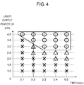
- FIG. 4 illustrates an effect produced by a relationship between laser output power and a laser irradiation time in a first zinc vapor discharge step.
- FIG. 5 illustrates an effect produced by a relationship between laser output power and a number of revolutions of a spiral movement in a second zinc vapor discharge step.
- a laser welding device in this exemplary embodiment will not be described, because this laser welding device is identical to the laser welding device in the first exemplary embodiment.
- a laser welding method in this exemplary embodiment will be described with reference to FIG. 3A to FIG. 3C .
- the laser welding method in this exemplary embodiment further includes a second zinc vapor discharge step to be performed between the first zinc vapor discharge step and the main welding step in the first exemplary embodiment.
- the first zinc vapor discharge step and the main welding step which are identical to those in the first exemplary embodiment, will not be described.
- a region (second region) of workpiece 9 to be bonded by laser welding is irradiated with laser beam 10 (fourth step). This region is centered on the site of workpiece 9 which has been irradiated with laser beam 10 in the first zinc vapor discharge step.
- the output of laser beam 10 is set to output power W3 at which zinc can be evaporated from the contact surfaces of upper plate 13 and lower plate 14.
- Laser irradiation head 7 irradiates a preset region of workpiece 9 with laser beam 10 at output power W3.
- both of robot 2 and laser irradiation head 7 operate to move laser beam 10 within the laser-welded region in a spiral fashion.
- zinc is evaporated from the contact surfaces of upper plate 13 and lower plate 14, whereby zinc vapor 16 is discharged from a through-hole that has been created in the first zinc vapor discharge step. This step is referred to as the second zinc vapor discharge step.
- the second zinc vapor discharge step will be described more concretely.
- Output power W3 of laser beam 10 in the second zinc vapor discharge step is preferably set to be smaller than both output power W1 of laser beam 10 in the first zinc vapor discharge step and output power W2 of laser beam 10 in the main welding step.
- the second zinc vapor discharge step is a step of evaporating zinc in the contact surfaces of upper plate 13 and lower plate 14 and discharging the evaporated zinc through the through-hole that has been created in the first zinc vapor discharge step. Therefore, the second zinc vapor discharge step does not have to melt iron with laser beam 10 and has only to evaporate zinc in the contact surfaces of upper plate 13 and lower plate 14 by heating upper plate 13 with laser beam 10. By heating upper plate 13, the heat is transferred from upper plate 13 to an entire laser-welded region, so that zinc in the contact surfaces of upper plate 13 and lower plate 14 is evaporated. Zinc vapor 16 thus generated is discharged to the outside of workpiece 9 through the through-hole.
- robot 2 moves laser beam 10 from the site of workpiece 9 which has been irradiated with laser beam 10 in the first zinc vapor discharge step (from substantially the center of the region bonded by the laser welding) to the outside.
- a movement of laser beam 10 is not limited to this method.
- controller 3 may move laser beam 10 from the outer circumference of the region bonded by the laser welding to the inside (the site irradiated with laser beam 10 in the first zinc vapor discharge step).
- controller 3 may move laser beam 10 so as to reciprocate between the center of the region bonded by the laser welding and the outer circumference of this region.
- controller 3 causes laser oscillator 1 to continue to output laser beam 10 between the first zinc vapor discharge step and the second zinc vapor discharge step by switching the outputs of laser beam 10 without stopping outputting laser beam 10. This can shorten a laser welding time.
- controller 3 may stop laser oscillator 1 from outputting laser beam 10 between the first zinc vapor discharge step and the second zinc vapor discharge step. In this case, in the second zinc vapor discharge step, controller 3 can change or select a direction of the spiral movement of laser beam 10 and can arbitrarily set an initial location to be irradiated with laser beam 10.
- controller 3 may set an initial location in workpiece 9 to be irradiated with laser beam 10 to a location displaced outwardly by 1 mm from the center of the region bonded by the laser welding and may move laser beam 10 toward the outer circumference of the bonded region.
- controller 3 may set an initial location in workpiece 9 to be irradiated with laser beam 10 to the outer circumference of the region bonded by laser welding and may finish moving laser beam 10 at a location displaced by 1 mm outwardly from the center of the bonded region.
- controller 3 causes laser oscillator 1 to continue to output laser beam 10 between the second zinc vapor discharge step and the main welding step by switching the outputs of laser beam 10 without stopping outputting laser beam 10. This can also shorten a laser welding time.
- controller 3 may stop laser oscillator 1 from outputting laser beam 10 between the first zinc vapor discharge step and the second zinc vapor discharge step. This can provide a high degree of flexibility in selecting an initial location in workpiece 9 to be irradiated with laser beam 10, for example.
- the switching between two steps is done twice. More specifically, a first step of switching from the first zinc vapor discharge step to the second zinc vapor discharge step and a second step of switching from the second zinc vapor discharge step to the main welding step are performed.
- the laser welding method in this exemplary embodiment may employ various switching manners. As an example, laser oscillator 1 may continue to output a laser beam in both the first and second switching steps. As another example, laser oscillator 1 may stop outputting a laser beam in both the first and second switching steps. As still another example, laser oscillator 1 may continue to output a laser beam in one of the first and second switching steps and may stop outputting a laser beam in the other of the first and second switching steps.
- the second zinc vapor discharge step may be optional.
- the first zinc vapor discharge step can discharge zinc vapor 16 to some extent.
- output power W1 of laser beam 10 is set to a high value in order to cause laser beam 10 to penetrate workpiece 9. Because of a small thickness of workpiece 9, the heat is transferred from a site of workpiece 9 adjoining the through-hole to a site of workpiece 9 adjoining the outer circumference of the region bonded by the laser welding, so that zinc vapor 16 is sufficiently generated.
- each of upper plate 13 and lower plate 14 has a thickness of 1.6 mm or greater, there are cases where the heat is not transferred from a site of workpiece 9 adjoining the through-hole to a site of workpiece 9 adjoining the outer circumference of the region bonded by the laser welding. In such cases, zinc vapor 16 may be insufficiently generated. Thus, the second zinc vapor discharge step is effective in discharging zinc vapor 16, especially when heat is not sufficiently transferred in workpiece 9.
- Laser output control section 6 sets an output of laser beam 10 in each of the first zinc vapor discharge step, the second zinc vapor discharge step, and the main welding step by controlling laser oscillator 1 in accordance with an instruction (output control command) from welding condition setting section 4.
- Laser output control section 6 incorporates a program including patterns related to different output values of laser beam 10. This program is used to switch laser outputs.
- laser oscillator 1 outputs laser beam 10
- laser beam 10 is transmitted to laser irradiation head 7 through optical fiber 8.
- a program incorporated in laser output control section 6 is derived from experimental data regarding laser welding related to various thicknesses.
- Operation control section 5 moves laser beam 10 in the first zinc vapor discharge step, second zinc vapor discharge step, and main welding step by controlling both robot 2 and laser irradiation head 7 in accordance with an instruction (position control command) from welding condition setting section 4.
- controller 3 controls an output of laser oscillator 1, a location of robot 2, and a location of laser irradiation head 7 in synchronization with one another.
- welding condition setting section 4, operation control section 5, and laser output control section 6, which constitute controller 3 adjust an energy density of laser beam 10.
- FIG. 4 illustrates an effect produced by a relationship between a laser irradiation time and laser output power in the first zinc vapor discharge step.
- a coating weight is 45 g/m 2
- two galvanized steel plates each having a thickness of 1.6 mm are stacked on each other.
- the horizontal axis represents a laser irradiation time t (second) and the vertical axis represents laser output power LW (kW).
- Performance levels of through-holes formed are expressed by the marks “circle,” “triangle,” and “cross.” After the first zinc vapor discharge step had been performed, the through-holes are visually checked. The mark “circle” indicates that a through-hole is sufficiently formed; the mark “triangle” indicates that a through-hole is insufficiently formed; and the mark "cross” indicates that no through-hole is formed.
- the experimental evaluation result reveals the following facts.
- the laser output needs to be set to 3.0 kW or higher in order to cause laser beam 10 to penetrate workpiece 9.
- the laser irradiation time needs to be increased as the laser output power decreases. When the laser output or the laser irradiation time decreases, the through-hole is insufficiently formed or not formed.
- FIG. 5 illustrates an effect produced by the relationship between laser output power and a number of revolutions of a spiral movement in the second zinc vapor discharge step.
- a coating weight is 45 g/m 2
- two galvanized steel plates each having a thickness of 1.6 mm are stacked on each other, similarly to the experimental evaluation for the first zinc vapor discharge step.
- the speed of a spiral movement (welding) of laser beam 10 is 10 m/min.
- the horizontal axis represents a number of revolutions (times) of the spiral movement
- the vertical axis represents the laser output power LW (kW).
- a result of discharge of zinc vapor 16 is expressed by the marks “circle,” “triangle,” and “cross.” After the second zinc vapor discharge step had been performed, through-holes are visually checked. The mark “circle” indicates that zinc vapor 16 is sufficiently discharged; the mark “triangle” indicates that the heating effect is insufficient and thus zinc vapor 16 is insufficiently discharged; and the mark “cross” indicates that overheating generates an excessive amount of zinc vapor 16 and leaves pores.
- the experimental evaluation result reveals that it is necessary to balance the laser output and a number of revolutions of the spiral movement in order to optimize discharging of zinc vapor 16. More specifically, when the laser output increases, it is necessary to decrease the number of revolutions of a spiral movement. When the laser output decreases, it is necessary to increase the number of revolutions of the spiral movement. As the number of revolutions of the spiral movement is larger, a route along which workpiece 9 is irradiated with laser beam 10 is longer, that is, an irradiation time of laser beam 10 is longer, because laser beam 10 moves at a constant speed (10 m/min). Both the laser output and the number of revolutions of the spiral movement are preferably set such that zinc vapor 16 is discharged readily. When the laser output increases, the number of revolutions of the spiral movement may be decreased to shorten the welding time.
- laser welding is applied to two galvanized steel plates stacked on each other.
- laser welding is also applicable to three or more galvanized steel plates stacked on top of one another.
- galvanized steel plates are formed by coating an iron material with zinc.
- any other steel plates whose boiling point is lower than the melting point of a metal formed on their surfaces may be used.
- Example of such steel plates include steel plates coated with an alloy of aluminum, zinc, and silicon (e.g., Galvalume steel plate) and steel plates coated with zinc to which aluminum and magnesium are added (e.g.,Galtite).
- the laser welding method and the laser welding device for use in welding galvanized steel plates or other surface-treated steel plates are industrially effective in reducing formation of pores in the interior and surface of a weld bead.
Landscapes
- Engineering & Computer Science (AREA)
- Physics & Mathematics (AREA)
- Optics & Photonics (AREA)
- Mechanical Engineering (AREA)
- Plasma & Fusion (AREA)
- Robotics (AREA)
- Laser Beam Processing (AREA)
Claims (12)
- Procédé de soudage au laser qui comprend :une première étape d'empilement d'une première pièce à usiner et d'une seconde pièce à usiner l'une sur l'autre, chacune de la première pièce à usiner et de la seconde pièce à usiner présentant une surface revêtue d'un premier matériau (11), chacune de la première pièce à usiner et de la seconde pièce à usiner étant fabriquée dans une second matériau (12), le second matériau (12) étant différent du premier matériau (11) ;une deuxième étape d'irradiation d'un faisceau laser sur une première région où la première pièce à usiner et la seconde pièce à usiner sont empilées l'une sur l'autre,dans lequel à la deuxième étape le faisceau laser pénètre tant la première pièce à usiner que la seconde pièce à usiner pour former un orifice traversant qui pénètre la première pièce à usiner et la seconde pièce à usiner, l'orifice traversant étant fabriqué dans un métal fondu ; et en ce que le procédé comprend en outreune troisième étape d'irradiation en spirale d'une deuxième région avec un faisceau laser après la deuxième étape, la deuxième région incluant la première région, la première pièce à usiner et la seconde pièce à usiner étant empilées l'une sur l'autre à l'intérieur de la deuxième région,caractérisé en ce qu'une émission du faisceau laser à la deuxième étape est plus élevée qu'une émission du faisceau laser à la troisième étape.
- Procédé de soudage au laser selon la revendication 1, dans lequel
la deuxième étape et la troisième étape sont réalisées de façon séquentielle sans l'arrêt d'une émission du faisceau laser. - Procédé de soudage au laser selon la revendication 1, dans lequel
une émission du faisceau laser est arrêtée temporairement entre la deuxième étape et la troisième étape. - Procédé de soudage au laser selon la revendication 1, qui comprend en outre une quatrième étape d'irradiation en spirale d'une troisième région avec un faisceau laser, la troisième région incluant la première région, la quatrième étape étant réalisée entre la deuxième étape et la troisième étape.
- Procédé de soudage au laser selon la revendication 4, dans lequel
la deuxième étape et la quatrième étape sont réalisées de façon séquentielle sans l'arrêt d'une émission du faisceau laser. - Procédé de soudage au laser selon la revendication 4 ou 5, dans lequel
la quatrième étape et la troisième étape sont réalisées de façon séquentielle sans l'arrêt d'une émission du faisceau laser. - Procédé de soudage au laser selon la revendication 4, dans lequel
une émission du faisceau laser est arrêtée temporairement entre la deuxième étape et la quatrième étape. - Procédé de soudage au laser selon la revendication 4 ou 7, dans lequel
une émission du faisceau laser est arrêtée temporairement entre la quatrième étape et la troisième étape. - Procédé de soudage au laser selon l'une quelconque des revendications 4 à 8, dans lequel
une émission du faisceau laser à la quatrième étape est plus basse qu'une émission du faisceau laser à la deuxième étape et est plus basse qu'une émission du faisceau laser à la troisième étape. - Procédé de soudage au laser selon l'une quelconque des revendications 1 à 9, dans lequel
de la vapeur de zinc passe à travers le métal fondu dans l'orifice traversant et est évacuée. - Dispositif de soudage au laser destiné à être utilisé dans le procédé de soudage au laser selon la revendication 1 qui comprend :un oscillateur de laser (1) qui émet un faisceau laser ;une tête de laser (7) à travers laquelle une première pièce à usiner et une seconde pièce à usiner peuvent être irradiées avec le faisceau laser, la première pièce à usiner et la seconde pièce à usiner étant empilées l'une sur l'autre, chacune de la première pièce à usiner et de la seconde pièce à usiner présentant une surface revêtue d'un premier matériau (11), chacune de la première pièce à usiner et de la seconde pièce à usiner étant fabriquée dans une second matériau (12), le second matériau (12) étant différent du premier matériau (11) ;un robot (2) équipé avec la tête de laser (7) ; etune unité de commande (3) qui commande une émission de l'oscillateur de laser (1), un fonctionnement de la tête de laser (7) et un fonctionnement du robot (2),caractérisé en ce quel'unité de commande (3) incorpore un programme qui commande une émission d'un faisceau laser pour irradier un faisceau laser sur une première région où la première pièce à usiner et la seconde pièce à usiner sont empilées l'une sur l'autre,dans lequel ni le robot (2) ni la tête de laser (7) ne fonctionnent pendant que la tête de laser (7) est en train d'irradier la première région avec le faisceau laser, et dans lequel le faisceau laser est agencé pour pénétrer tant la première pièce à usiner que la seconde pièce à usiner afin de former un orifice traversant qui pénètre la première pièce à usiner et la seconde pièce à usiner et qui, après que la première région a été irradiée avec le faisceau laser, commande une émission d'un faisceau laser pour irradier en spirale avec un faisceau laser une deuxième région dans laquelle la première pièce à usiner et la seconde pièce à usiner sont empilées l'une sur l'autre, la deuxième région incluant la première région, etdans lequel le programme commande une émission du faisceau laser avec laquelle la première région est irradiée pour qu'elle soit plus élevée qu'une émission du faisceau laser avec laquelle la deuxième région est irradiée.
- Dispositif de soudage au laser selon la revendication 11, dans lequell'unité de commande (3) inclut :une section de réglage de condition de soudage (4) qui règle une condition de soudage ;une section de commande d'émission laser (6) qui commande une émission du faisceau laser depuis l'oscillateur de laser (1), sur la base de la condition de soudage réglée par la section de réglage de condition de soudage (4) ; etune section de commande de fonctionnement (5) qui commande le fonctionnement de la tête de laser (7) et le fonctionnement du robot (2), sur la base de la condition de soudage réglée par la section de réglage de condition de soudage (4), etl'unité de commande (3) incorpore le programme.
Applications Claiming Priority (2)
| Application Number | Priority Date | Filing Date | Title |
|---|---|---|---|
| JP2014002891 | 2014-01-10 | ||
| PCT/JP2014/006453 WO2015104781A1 (fr) | 2014-01-10 | 2014-12-25 | Appareil de soudage au laser et procédé de soudage au laser |
Publications (3)
| Publication Number | Publication Date |
|---|---|
| EP3093096A1 EP3093096A1 (fr) | 2016-11-16 |
| EP3093096A4 EP3093096A4 (fr) | 2017-01-11 |
| EP3093096B1 true EP3093096B1 (fr) | 2022-12-07 |
Family
ID=53523638
Family Applications (1)
| Application Number | Title | Priority Date | Filing Date |
|---|---|---|---|
| EP14878251.9A Active EP3093096B1 (fr) | 2014-01-10 | 2014-12-25 | Appareil de soudage au laser et procédé de soudage au laser |
Country Status (5)
| Country | Link |
|---|---|
| US (1) | US10155285B2 (fr) |
| EP (1) | EP3093096B1 (fr) |
| JP (1) | JP6518945B2 (fr) |
| CN (1) | CN105899323B (fr) |
| WO (1) | WO2015104781A1 (fr) |
Families Citing this family (36)
| Publication number | Priority date | Publication date | Assignee | Title |
|---|---|---|---|---|
| JP6149887B2 (ja) * | 2015-04-03 | 2017-06-21 | トヨタ自動車株式会社 | 溶接方法 |
| US10835993B2 (en) * | 2015-08-05 | 2020-11-17 | Panasonic Intellectual Property Management Co., Ltd. | Laser welding method |
| WO2017124216A1 (fr) * | 2016-01-18 | 2017-07-27 | GM Global Technology Operations LLC | Procédé de soudage laser par points d'aciers enduits |
| WO2017173650A1 (fr) * | 2016-04-08 | 2017-10-12 | GM Global Technology Operations LLC | Procédé de soudage au laser de pièces à travailler en acier |
| CN109153097A (zh) * | 2016-04-14 | 2019-01-04 | 通用汽车环球科技运作有限责任公司 | 经涂覆的钢的集成预钻和激光点焊 |
| WO2018010132A1 (fr) * | 2016-07-14 | 2018-01-18 | GM Global Technology Operations LLC | Soudage par points par laser à faisceaux multiples d'aciers revêtus |
| DE102017117992B4 (de) | 2016-08-11 | 2024-05-23 | GM Global Technology Operations LLC | Verfahren zum laserschweissen eines werkstückstapels unter verwendung von spiralförmigen strecken |
| JP6719348B2 (ja) * | 2016-09-14 | 2020-07-08 | 株式会社神戸製鋼所 | アルミニウム接合体の製造方法 |
| US10661381B2 (en) * | 2017-02-24 | 2020-05-26 | Spirit Aerosystems, Inc. | Structure and method of making same involving welding otherwise non-weldable materials |
| CN110234460B (zh) * | 2017-02-24 | 2021-06-29 | Nok株式会社 | 激光焊接方法 |
| CA3055275A1 (fr) * | 2017-03-03 | 2018-09-07 | Furukawa Electric Co., Ltd. | Procede de soudage et dispositif de soudage |
| CN107252971B (zh) * | 2017-04-20 | 2019-11-19 | 武汉华工激光工程有限责任公司 | 镀锌板激光叠焊方法 |
| CN110914014B (zh) * | 2017-06-13 | 2021-07-20 | 通用汽车环球科技运作有限责任公司 | 用于使用焊接路径的组合激光焊接金属工件的方法 |
| JP6852588B2 (ja) * | 2017-06-20 | 2021-03-31 | トヨタ自動車株式会社 | レーザ溶接方法及びレーザ溶接装置 |
| JP7058955B2 (ja) | 2017-07-28 | 2022-04-25 | 日本発條株式会社 | 溶接部を有するワークと、ワークのための溶接装置と、溶接方法 |
| EP3441178A1 (fr) * | 2017-08-09 | 2019-02-13 | Autotech Engineering A.I.E. | Procédé d'assemblage de deux ébauches |
| EP3733339B1 (fr) * | 2017-12-28 | 2024-02-07 | Fujikura Ltd. | Structure de soudage, carte câblée avec pièce métallique |
| CN111093887B (zh) * | 2018-02-16 | 2022-06-28 | 松下知识产权经营株式会社 | 激光焊接装置及激光焊接方法 |
| JP6845170B2 (ja) * | 2018-03-13 | 2021-03-17 | 株式会社東芝 | レーザ加工方法 |
| CN108326425B (zh) * | 2018-03-20 | 2021-01-01 | 北京工业大学 | 一种焦点平面旋转激光点焊焊接方法 |
| HUE072679T2 (hu) * | 2018-03-30 | 2025-12-28 | Furukawa Electric Co Ltd | Hegesztési eljárás és hegesztõkészülék |
| WO2019198443A1 (fr) * | 2018-04-13 | 2019-10-17 | パナソニックIpマネジメント株式会社 | Dispositif de soudage au laser |
| CN115609151B (zh) * | 2018-08-30 | 2026-01-16 | 罗姆股份有限公司 | 半导体装置 |
| US11203085B2 (en) * | 2018-09-25 | 2021-12-21 | GM Global Technology Operations LLC | Method and apparatus for laser welding |
| DE102018217526A1 (de) * | 2018-10-12 | 2020-04-16 | Trumpf Werkzeugmaschinen Gmbh + Co. Kg | Verfahren zum Ermitteln einer Kenngröße eines Bearbeitungsprozesses und Bearbeitungsmaschine |
| JP7535697B2 (ja) * | 2020-06-11 | 2024-08-19 | パナソニックIpマネジメント株式会社 | 生成方法、推定方法、生成装置、および推定装置 |
| CN113967788B (zh) * | 2020-07-24 | 2024-04-12 | 中国科学院上海光学精密机械研究所 | 一种堆叠钢工件的远程激光焊接方法 |
| US11701738B2 (en) * | 2020-09-29 | 2023-07-18 | GM Global Technology Operations LLC | Laser welded assembly having a heat affected zone reinforcement and method of making the same |
| CN115812015B (zh) * | 2020-10-05 | 2025-10-28 | 松下知识产权经营株式会社 | 激光焊接方法以及激光焊接装置 |
| WO2022092042A1 (fr) * | 2020-10-30 | 2022-05-05 | ファナック株式会社 | Procédé de soudage au laser pour pièce à usiner |
| DE102021109787A1 (de) * | 2021-04-19 | 2022-10-20 | Precitec Gmbh & Co. Kg | Verfahren zum Vergleichen von Laserbearbeitungssystemen und Verfahren zum Überwachen eines Laserbearbeitungsprozesses sowie dazugehöriges Laserbearbeitungssystem |
| WO2023110583A1 (fr) * | 2021-12-17 | 2023-06-22 | Trumpf Laser- Und Systemtechnik Gmbh | Procédé de soudage de tôles d'acier revêtues de zinc à l'aide d'un faisceau laser |
| JP7593355B2 (ja) * | 2022-03-11 | 2024-12-03 | トヨタ自動車株式会社 | レーザ溶接方法およびレーザ溶接装置 |
| JP7639752B2 (ja) * | 2022-03-30 | 2025-03-05 | トヨタ自動車株式会社 | レーザー溶接方法 |
| CN118650283B (zh) * | 2024-07-17 | 2025-11-18 | 凌云吉恩斯科技有限公司 | 一种补丁板激光螺旋焊接工艺 |
| CN121296467B (zh) * | 2025-12-10 | 2026-03-10 | 冰山松洋压缩机(大连)有限公司 | 全封闭涡旋压缩机用驱动组件及实现方法 |
Citations (1)
| Publication number | Priority date | Publication date | Assignee | Title |
|---|---|---|---|---|
| JP2011173146A (ja) * | 2010-02-24 | 2011-09-08 | Mazda Motor Corp | レーザ溶接方法 |
Family Cites Families (18)
| Publication number | Priority date | Publication date | Assignee | Title |
|---|---|---|---|---|
| US3881084A (en) * | 1973-10-04 | 1975-04-29 | Ford Motor Co | Method of welding galvanized steel |
| US4873415A (en) * | 1988-02-02 | 1989-10-10 | Raycon Corporation | Method for welding galvanized material |
| US5603853A (en) * | 1995-02-28 | 1997-02-18 | The Twentyfirst Century Corporation | Method of high energy density radiation beam lap welding |
| FR2830477B1 (fr) * | 2001-10-09 | 2004-02-06 | Usinor | Procede et dispositif de soudage par recouvrement a l'aide d'un faisceau a haute densite d'energie de deux toles revetues |
| DE10262053A1 (de) | 2002-09-05 | 2004-08-12 | Daimlerchrysler Ag | Verfahren zur Laserbearbeitung beschichteter Bleche |
| US6794603B1 (en) * | 2003-03-03 | 2004-09-21 | Dana Corporation | Laser joint welding metal material |
| DE102004005358B4 (de) | 2004-02-03 | 2007-03-22 | Daimlerchrysler Ag | Verfahren zur Laserbearbeitung beschichteter Bleche und beschichtetes Blech |
| DE102004025935B4 (de) | 2004-05-27 | 2009-03-19 | Daimler Ag | Verfahren zur Prüfung des Abstandes beschichteter Bleche für deren Schweissbearbeitung |
| JP5040125B2 (ja) * | 2006-03-06 | 2012-10-03 | 日産自動車株式会社 | レーザ溶接方法および装置 |
| JP4867599B2 (ja) | 2006-11-16 | 2012-02-01 | 日産自動車株式会社 | レーザ溶接方法およびその装置 |
| JP5196128B2 (ja) | 2007-12-19 | 2013-05-15 | マツダ株式会社 | レーザ溶接方法 |
| JP4620753B2 (ja) * | 2008-04-24 | 2011-01-26 | 東亜工業株式会社 | 金属メッキ板のレーザー溶接方法 |
| JP2010046674A (ja) * | 2008-08-19 | 2010-03-04 | Nissan Motor Co Ltd | レーザ溶接方法、レーザ溶接装置、および溶接部材 |
| JP5609595B2 (ja) | 2010-12-01 | 2014-10-22 | トヨタ自動車株式会社 | レーザ溶接方法 |
| JP2012170989A (ja) | 2011-02-22 | 2012-09-10 | Suzuki Motor Corp | レーザ重ね溶接方法 |
| JP5902400B2 (ja) | 2011-04-26 | 2016-04-13 | トヨタ自動車株式会社 | レーザ溶接装置、レーザ溶接方法、鋼板積層体の製造方法及び積層体のレーザ溶接による溶接構造 |
| KR101272050B1 (ko) * | 2011-11-11 | 2013-06-07 | 주식회사 성우하이텍 | 레이저 용접방법 |
| DE102012008940B4 (de) | 2012-05-08 | 2022-03-24 | Fraunhofer-Gesellschaft zur Förderung der angewandten Forschung e.V. | Verfahren zum Fügen von mindestens zwei Werkstücken |
-
2014
- 2014-12-25 WO PCT/JP2014/006453 patent/WO2015104781A1/fr not_active Ceased
- 2014-12-25 CN CN201480072543.2A patent/CN105899323B/zh active Active
- 2014-12-25 JP JP2015556648A patent/JP6518945B2/ja not_active Expired - Fee Related
- 2014-12-25 EP EP14878251.9A patent/EP3093096B1/fr active Active
- 2014-12-25 US US15/107,347 patent/US10155285B2/en active Active
Patent Citations (1)
| Publication number | Priority date | Publication date | Assignee | Title |
|---|---|---|---|---|
| JP2011173146A (ja) * | 2010-02-24 | 2011-09-08 | Mazda Motor Corp | レーザ溶接方法 |
Also Published As
| Publication number | Publication date |
|---|---|
| JPWO2015104781A1 (ja) | 2017-03-23 |
| JP6518945B2 (ja) | 2019-05-29 |
| CN105899323A (zh) | 2016-08-24 |
| US20170001261A1 (en) | 2017-01-05 |
| EP3093096A1 (fr) | 2016-11-16 |
| WO2015104781A1 (fr) | 2015-07-16 |
| US10155285B2 (en) | 2018-12-18 |
| EP3093096A4 (fr) | 2017-01-11 |
| CN105899323B (zh) | 2018-02-16 |
Similar Documents
| Publication | Publication Date | Title |
|---|---|---|
| EP3093096B1 (fr) | Appareil de soudage au laser et procédé de soudage au laser | |
| EP3305458B1 (fr) | Procédé de soudage au laser | |
| JP6554670B2 (ja) | レーザ溶接方法 | |
| EP3332904B1 (fr) | Procédé de soudage laser | |
| JP5104945B2 (ja) | 複合溶接方法と複合溶接装置 | |
| CN104334349B (zh) | 具有焊接凹口的金属板材件及其形成方法 | |
| US20130112672A1 (en) | Laser configuration for additive manufacturing | |
| JP7449863B2 (ja) | 溶接方法および溶接装置 | |
| KR20150086485A (ko) | 금속 박편에 용접 노치를 형성하는 방법 | |
| CN110234462A (zh) | 用于将构件焊接的方法 | |
| KR20240010732A (ko) | 금속 접합을 위한 나선형 레이저 용접 방법 | |
| JP4867599B2 (ja) | レーザ溶接方法およびその装置 | |
| JP2009050894A (ja) | レーザ溶接方法及びレーザ溶接装置 | |
| KR20170058427A (ko) | 레이저 용접 조인트 및 그 제조 방법 | |
| KR101428973B1 (ko) | 레이저 용접방법 | |
| JP2015199111A (ja) | 溶接構造体の製造方法 | |
| CA3054472C (fr) | Procede de soudage au laser cote frontal | |
| KR102158855B1 (ko) | 레이저 용접 장치 및 방법 |
Legal Events
| Date | Code | Title | Description |
|---|---|---|---|
| PUAI | Public reference made under article 153(3) epc to a published international application that has entered the european phase |
Free format text: ORIGINAL CODE: 0009012 |
|
| 17P | Request for examination filed |
Effective date: 20160622 |
|
| AK | Designated contracting states |
Kind code of ref document: A1 Designated state(s): AL AT BE BG CH CY CZ DE DK EE ES FI FR GB GR HR HU IE IS IT LI LT LU LV MC MK MT NL NO PL PT RO RS SE SI SK SM TR |
|
| AX | Request for extension of the european patent |
Extension state: BA ME |
|
| A4 | Supplementary search report drawn up and despatched |
Effective date: 20161213 |
|
| RIC1 | Information provided on ipc code assigned before grant |
Ipc: B23K 26/21 20140101AFI20161207BHEP Ipc: B23K 26/22 20060101ALI20161207BHEP Ipc: B23K 26/082 20140101ALI20161207BHEP |
|
| DAX | Request for extension of the european patent (deleted) | ||
| STAA | Information on the status of an ep patent application or granted ep patent |
Free format text: STATUS: EXAMINATION IS IN PROGRESS |
|
| 17Q | First examination report despatched |
Effective date: 20190808 |
|
| GRAP | Despatch of communication of intention to grant a patent |
Free format text: ORIGINAL CODE: EPIDOSNIGR1 |
|
| STAA | Information on the status of an ep patent application or granted ep patent |
Free format text: STATUS: GRANT OF PATENT IS INTENDED |
|
| INTG | Intention to grant announced |
Effective date: 20220707 |
|
| GRAS | Grant fee paid |
Free format text: ORIGINAL CODE: EPIDOSNIGR3 |
|
| GRAA | (expected) grant |
Free format text: ORIGINAL CODE: 0009210 |
|
| STAA | Information on the status of an ep patent application or granted ep patent |
Free format text: STATUS: THE PATENT HAS BEEN GRANTED |
|
| AK | Designated contracting states |
Kind code of ref document: B1 Designated state(s): AL AT BE BG CH CY CZ DE DK EE ES FI FR GB GR HR HU IE IS IT LI LT LU LV MC MK MT NL NO PL PT RO RS SE SI SK SM TR |
|
| REG | Reference to a national code |
Ref country code: GB Ref legal event code: FG4D |
|
| REG | Reference to a national code |
Ref country code: CH Ref legal event code: EP Ref country code: AT Ref legal event code: REF Ref document number: 1536011 Country of ref document: AT Kind code of ref document: T Effective date: 20221215 |
|
| REG | Reference to a national code |
Ref country code: DE Ref legal event code: R096 Ref document number: 602014085764 Country of ref document: DE |
|
| REG | Reference to a national code |
Ref country code: IE Ref legal event code: FG4D |
|
| REG | Reference to a national code |
Ref country code: LT Ref legal event code: MG9D |
|
| REG | Reference to a national code |
Ref country code: NL Ref legal event code: MP Effective date: 20221207 |
|
| PG25 | Lapsed in a contracting state [announced via postgrant information from national office to epo] |
Ref country code: SE Free format text: LAPSE BECAUSE OF FAILURE TO SUBMIT A TRANSLATION OF THE DESCRIPTION OR TO PAY THE FEE WITHIN THE PRESCRIBED TIME-LIMIT Effective date: 20221207 Ref country code: NO Free format text: LAPSE BECAUSE OF FAILURE TO SUBMIT A TRANSLATION OF THE DESCRIPTION OR TO PAY THE FEE WITHIN THE PRESCRIBED TIME-LIMIT Effective date: 20230307 Ref country code: LT Free format text: LAPSE BECAUSE OF FAILURE TO SUBMIT A TRANSLATION OF THE DESCRIPTION OR TO PAY THE FEE WITHIN THE PRESCRIBED TIME-LIMIT Effective date: 20221207 Ref country code: FI Free format text: LAPSE BECAUSE OF FAILURE TO SUBMIT A TRANSLATION OF THE DESCRIPTION OR TO PAY THE FEE WITHIN THE PRESCRIBED TIME-LIMIT Effective date: 20221207 Ref country code: ES Free format text: LAPSE BECAUSE OF FAILURE TO SUBMIT A TRANSLATION OF THE DESCRIPTION OR TO PAY THE FEE WITHIN THE PRESCRIBED TIME-LIMIT Effective date: 20221207 |
|
| REG | Reference to a national code |
Ref country code: AT Ref legal event code: MK05 Ref document number: 1536011 Country of ref document: AT Kind code of ref document: T Effective date: 20221207 |
|
| PG25 | Lapsed in a contracting state [announced via postgrant information from national office to epo] |
Ref country code: RS Free format text: LAPSE BECAUSE OF FAILURE TO SUBMIT A TRANSLATION OF THE DESCRIPTION OR TO PAY THE FEE WITHIN THE PRESCRIBED TIME-LIMIT Effective date: 20221207 Ref country code: PL Free format text: LAPSE BECAUSE OF FAILURE TO SUBMIT A TRANSLATION OF THE DESCRIPTION OR TO PAY THE FEE WITHIN THE PRESCRIBED TIME-LIMIT Effective date: 20221207 Ref country code: LV Free format text: LAPSE BECAUSE OF FAILURE TO SUBMIT A TRANSLATION OF THE DESCRIPTION OR TO PAY THE FEE WITHIN THE PRESCRIBED TIME-LIMIT Effective date: 20221207 Ref country code: HR Free format text: LAPSE BECAUSE OF FAILURE TO SUBMIT A TRANSLATION OF THE DESCRIPTION OR TO PAY THE FEE WITHIN THE PRESCRIBED TIME-LIMIT Effective date: 20221207 Ref country code: GR Free format text: LAPSE BECAUSE OF FAILURE TO SUBMIT A TRANSLATION OF THE DESCRIPTION OR TO PAY THE FEE WITHIN THE PRESCRIBED TIME-LIMIT Effective date: 20230308 |
|
| PG25 | Lapsed in a contracting state [announced via postgrant information from national office to epo] |
Ref country code: NL Free format text: LAPSE BECAUSE OF FAILURE TO SUBMIT A TRANSLATION OF THE DESCRIPTION OR TO PAY THE FEE WITHIN THE PRESCRIBED TIME-LIMIT Effective date: 20221207 |
|
| PG25 | Lapsed in a contracting state [announced via postgrant information from national office to epo] |
Ref country code: SM Free format text: LAPSE BECAUSE OF FAILURE TO SUBMIT A TRANSLATION OF THE DESCRIPTION OR TO PAY THE FEE WITHIN THE PRESCRIBED TIME-LIMIT Effective date: 20221207 Ref country code: RO Free format text: LAPSE BECAUSE OF FAILURE TO SUBMIT A TRANSLATION OF THE DESCRIPTION OR TO PAY THE FEE WITHIN THE PRESCRIBED TIME-LIMIT Effective date: 20221207 Ref country code: PT Free format text: LAPSE BECAUSE OF FAILURE TO SUBMIT A TRANSLATION OF THE DESCRIPTION OR TO PAY THE FEE WITHIN THE PRESCRIBED TIME-LIMIT Effective date: 20230410 Ref country code: EE Free format text: LAPSE BECAUSE OF FAILURE TO SUBMIT A TRANSLATION OF THE DESCRIPTION OR TO PAY THE FEE WITHIN THE PRESCRIBED TIME-LIMIT Effective date: 20221207 Ref country code: CZ Free format text: LAPSE BECAUSE OF FAILURE TO SUBMIT A TRANSLATION OF THE DESCRIPTION OR TO PAY THE FEE WITHIN THE PRESCRIBED TIME-LIMIT Effective date: 20221207 Ref country code: AT Free format text: LAPSE BECAUSE OF FAILURE TO SUBMIT A TRANSLATION OF THE DESCRIPTION OR TO PAY THE FEE WITHIN THE PRESCRIBED TIME-LIMIT Effective date: 20221207 |
|
| REG | Reference to a national code |
Ref country code: CH Ref legal event code: PL |
|
| REG | Reference to a national code |
Ref country code: BE Ref legal event code: MM Effective date: 20221231 |
|
| PG25 | Lapsed in a contracting state [announced via postgrant information from national office to epo] |
Ref country code: SK Free format text: LAPSE BECAUSE OF FAILURE TO SUBMIT A TRANSLATION OF THE DESCRIPTION OR TO PAY THE FEE WITHIN THE PRESCRIBED TIME-LIMIT Effective date: 20221207 Ref country code: LU Free format text: LAPSE BECAUSE OF NON-PAYMENT OF DUE FEES Effective date: 20221225 Ref country code: IS Free format text: LAPSE BECAUSE OF FAILURE TO SUBMIT A TRANSLATION OF THE DESCRIPTION OR TO PAY THE FEE WITHIN THE PRESCRIBED TIME-LIMIT Effective date: 20230407 Ref country code: AL Free format text: LAPSE BECAUSE OF FAILURE TO SUBMIT A TRANSLATION OF THE DESCRIPTION OR TO PAY THE FEE WITHIN THE PRESCRIBED TIME-LIMIT Effective date: 20221207 |
|
| REG | Reference to a national code |
Ref country code: DE Ref legal event code: R097 Ref document number: 602014085764 Country of ref document: DE |
|
| PG25 | Lapsed in a contracting state [announced via postgrant information from national office to epo] |
Ref country code: MC Free format text: LAPSE BECAUSE OF FAILURE TO SUBMIT A TRANSLATION OF THE DESCRIPTION OR TO PAY THE FEE WITHIN THE PRESCRIBED TIME-LIMIT Effective date: 20221207 |
|
| PLBE | No opposition filed within time limit |
Free format text: ORIGINAL CODE: 0009261 |
|
| STAA | Information on the status of an ep patent application or granted ep patent |
Free format text: STATUS: NO OPPOSITION FILED WITHIN TIME LIMIT |
|
| PG25 | Lapsed in a contracting state [announced via postgrant information from national office to epo] |
Ref country code: LI Free format text: LAPSE BECAUSE OF NON-PAYMENT OF DUE FEES Effective date: 20221231 Ref country code: IE Free format text: LAPSE BECAUSE OF NON-PAYMENT OF DUE FEES Effective date: 20221225 Ref country code: DK Free format text: LAPSE BECAUSE OF FAILURE TO SUBMIT A TRANSLATION OF THE DESCRIPTION OR TO PAY THE FEE WITHIN THE PRESCRIBED TIME-LIMIT Effective date: 20221207 Ref country code: CH Free format text: LAPSE BECAUSE OF NON-PAYMENT OF DUE FEES Effective date: 20221231 |
|
| 26N | No opposition filed |
Effective date: 20230908 |
|
| GBPC | Gb: european patent ceased through non-payment of renewal fee |
Effective date: 20230307 |
|
| PG25 | Lapsed in a contracting state [announced via postgrant information from national office to epo] |
Ref country code: SI Free format text: LAPSE BECAUSE OF FAILURE TO SUBMIT A TRANSLATION OF THE DESCRIPTION OR TO PAY THE FEE WITHIN THE PRESCRIBED TIME-LIMIT Effective date: 20221207 Ref country code: BE Free format text: LAPSE BECAUSE OF NON-PAYMENT OF DUE FEES Effective date: 20221231 |
|
| PG25 | Lapsed in a contracting state [announced via postgrant information from national office to epo] |
Ref country code: GB Free format text: LAPSE BECAUSE OF NON-PAYMENT OF DUE FEES Effective date: 20230307 |
|
| PG25 | Lapsed in a contracting state [announced via postgrant information from national office to epo] |
Ref country code: GB Free format text: LAPSE BECAUSE OF NON-PAYMENT OF DUE FEES Effective date: 20230307 Ref country code: FR Free format text: LAPSE BECAUSE OF NON-PAYMENT OF DUE FEES Effective date: 20230207 |
|
| PG25 | Lapsed in a contracting state [announced via postgrant information from national office to epo] |
Ref country code: HU Free format text: LAPSE BECAUSE OF FAILURE TO SUBMIT A TRANSLATION OF THE DESCRIPTION OR TO PAY THE FEE WITHIN THE PRESCRIBED TIME-LIMIT; INVALID AB INITIO Effective date: 20141225 |
|
| PG25 | Lapsed in a contracting state [announced via postgrant information from national office to epo] |
Ref country code: CY Free format text: LAPSE BECAUSE OF FAILURE TO SUBMIT A TRANSLATION OF THE DESCRIPTION OR TO PAY THE FEE WITHIN THE PRESCRIBED TIME-LIMIT Effective date: 20221207 |
|
| PG25 | Lapsed in a contracting state [announced via postgrant information from national office to epo] |
Ref country code: MK Free format text: LAPSE BECAUSE OF FAILURE TO SUBMIT A TRANSLATION OF THE DESCRIPTION OR TO PAY THE FEE WITHIN THE PRESCRIBED TIME-LIMIT Effective date: 20221207 Ref country code: IT Free format text: LAPSE BECAUSE OF FAILURE TO SUBMIT A TRANSLATION OF THE DESCRIPTION OR TO PAY THE FEE WITHIN THE PRESCRIBED TIME-LIMIT Effective date: 20221207 |
|
| PG25 | Lapsed in a contracting state [announced via postgrant information from national office to epo] |
Ref country code: BG Free format text: LAPSE BECAUSE OF FAILURE TO SUBMIT A TRANSLATION OF THE DESCRIPTION OR TO PAY THE FEE WITHIN THE PRESCRIBED TIME-LIMIT Effective date: 20221207 |
|
| PG25 | Lapsed in a contracting state [announced via postgrant information from national office to epo] |
Ref country code: MT Free format text: LAPSE BECAUSE OF FAILURE TO SUBMIT A TRANSLATION OF THE DESCRIPTION OR TO PAY THE FEE WITHIN THE PRESCRIBED TIME-LIMIT Effective date: 20221207 |
|
| PGFP | Annual fee paid to national office [announced via postgrant information from national office to epo] |
Ref country code: DE Payment date: 20241210 Year of fee payment: 11 |
|
| PG25 | Lapsed in a contracting state [announced via postgrant information from national office to epo] |
Ref country code: TR Free format text: LAPSE BECAUSE OF FAILURE TO SUBMIT A TRANSLATION OF THE DESCRIPTION OR TO PAY THE FEE WITHIN THE PRESCRIBED TIME-LIMIT Effective date: 20221207 |