EP3093104A2 - Magasin pour outils - Google Patents
Magasin pour outils Download PDFInfo
- Publication number
- EP3093104A2 EP3093104A2 EP16168976.5A EP16168976A EP3093104A2 EP 3093104 A2 EP3093104 A2 EP 3093104A2 EP 16168976 A EP16168976 A EP 16168976A EP 3093104 A2 EP3093104 A2 EP 3093104A2
- Authority
- EP
- European Patent Office
- Prior art keywords
- quiver
- magazine
- tool
- track
- drive
- Prior art date
- Legal status (The legal status is an assumption and is not a legal conclusion. Google has not performed a legal analysis and makes no representation as to the accuracy of the status listed.)
- Withdrawn
Links
- 238000000034 method Methods 0.000 description 6
- 230000008569 process Effects 0.000 description 6
- 238000003860 storage Methods 0.000 description 6
- 230000008859 change Effects 0.000 description 5
- 238000003754 machining Methods 0.000 description 5
- 230000008901 benefit Effects 0.000 description 3
- 230000005540 biological transmission Effects 0.000 description 3
- 230000009467 reduction Effects 0.000 description 3
- 230000000295 complement effect Effects 0.000 description 2
- 238000010276 construction Methods 0.000 description 2
- 230000003993 interaction Effects 0.000 description 2
- 238000004519 manufacturing process Methods 0.000 description 2
- 239000000463 material Substances 0.000 description 2
- 229920002430 Fibre-reinforced plastic Polymers 0.000 description 1
- 229910001060 Gray iron Inorganic materials 0.000 description 1
- 229910000760 Hardened steel Inorganic materials 0.000 description 1
- XAGFODPZIPBFFR-UHFFFAOYSA-N aluminium Chemical compound [Al] XAGFODPZIPBFFR-UHFFFAOYSA-N 0.000 description 1
- 229910052782 aluminium Inorganic materials 0.000 description 1
- 230000008878 coupling Effects 0.000 description 1
- 238000010168 coupling process Methods 0.000 description 1
- 238000005859 coupling reaction Methods 0.000 description 1
- 238000009826 distribution Methods 0.000 description 1
- 230000000694 effects Effects 0.000 description 1
- 238000005516 engineering process Methods 0.000 description 1
- 239000003365 glass fiber Substances 0.000 description 1
- 238000000227 grinding Methods 0.000 description 1
- 238000001746 injection moulding Methods 0.000 description 1
- 238000003801 milling Methods 0.000 description 1
- 229920003023 plastic Polymers 0.000 description 1
- 238000005096 rolling process Methods 0.000 description 1
- 238000000926 separation method Methods 0.000 description 1
- 239000000243 solution Substances 0.000 description 1
- 230000007704 transition Effects 0.000 description 1
- 238000007514 turning Methods 0.000 description 1
Images


Classifications
-
- B—PERFORMING OPERATIONS; TRANSPORTING
- B23—MACHINE TOOLS; METAL-WORKING NOT OTHERWISE PROVIDED FOR
- B23Q—DETAILS, COMPONENTS, OR ACCESSORIES FOR MACHINE TOOLS, e.g. ARRANGEMENTS FOR COPYING OR CONTROLLING; MACHINE TOOLS IN GENERAL CHARACTERISED BY THE CONSTRUCTION OF PARTICULAR DETAILS OR COMPONENTS; COMBINATIONS OR ASSOCIATIONS OF METAL-WORKING MACHINES, NOT DIRECTED TO A PARTICULAR RESULT
- B23Q3/00—Devices holding, supporting, or positioning work or tools, of a kind normally removable from the machine
- B23Q3/155—Arrangements for automatic insertion or removal of tools, e.g. combined with manual handling
- B23Q3/1552—Arrangements for automatic insertion or removal of tools, e.g. combined with manual handling parts of devices for automatically inserting or removing tools
- B23Q3/15526—Storage devices; Drive mechanisms therefor
-
- B—PERFORMING OPERATIONS; TRANSPORTING
- B23—MACHINE TOOLS; METAL-WORKING NOT OTHERWISE PROVIDED FOR
- B23Q—DETAILS, COMPONENTS, OR ACCESSORIES FOR MACHINE TOOLS, e.g. ARRANGEMENTS FOR COPYING OR CONTROLLING; MACHINE TOOLS IN GENERAL CHARACTERISED BY THE CONSTRUCTION OF PARTICULAR DETAILS OR COMPONENTS; COMBINATIONS OR ASSOCIATIONS OF METAL-WORKING MACHINES, NOT DIRECTED TO A PARTICULAR RESULT
- B23Q3/00—Devices holding, supporting, or positioning work or tools, of a kind normally removable from the machine
- B23Q3/155—Arrangements for automatic insertion or removal of tools, e.g. combined with manual handling
- B23Q3/157—Arrangements for automatic insertion or removal of tools, e.g. combined with manual handling of rotary tools
- B23Q3/15713—Arrangements for automatic insertion or removal of tools, e.g. combined with manual handling of rotary tools a transfer device taking a single tool from a storage device and inserting it in a spindle
- B23Q3/1572—Arrangements for automatic insertion or removal of tools, e.g. combined with manual handling of rotary tools a transfer device taking a single tool from a storage device and inserting it in a spindle the storage device comprising rotating or circulating storing means
- B23Q3/15724—Chains or belts
-
- B—PERFORMING OPERATIONS; TRANSPORTING
- B23—MACHINE TOOLS; METAL-WORKING NOT OTHERWISE PROVIDED FOR
- B23Q—DETAILS, COMPONENTS, OR ACCESSORIES FOR MACHINE TOOLS, e.g. ARRANGEMENTS FOR COPYING OR CONTROLLING; MACHINE TOOLS IN GENERAL CHARACTERISED BY THE CONSTRUCTION OF PARTICULAR DETAILS OR COMPONENTS; COMBINATIONS OR ASSOCIATIONS OF METAL-WORKING MACHINES, NOT DIRECTED TO A PARTICULAR RESULT
- B23Q3/00—Devices holding, supporting, or positioning work or tools, of a kind normally removable from the machine
- B23Q3/155—Arrangements for automatic insertion or removal of tools, e.g. combined with manual handling
- B23Q3/157—Arrangements for automatic insertion or removal of tools, e.g. combined with manual handling of rotary tools
- B23Q3/15713—Arrangements for automatic insertion or removal of tools, e.g. combined with manual handling of rotary tools a transfer device taking a single tool from a storage device and inserting it in a spindle
- B23Q3/1572—Arrangements for automatic insertion or removal of tools, e.g. combined with manual handling of rotary tools a transfer device taking a single tool from a storage device and inserting it in a spindle the storage device comprising rotating or circulating storing means
- B23Q3/15753—Arrangements for automatic insertion or removal of tools, e.g. combined with manual handling of rotary tools a transfer device taking a single tool from a storage device and inserting it in a spindle the storage device comprising rotating or circulating storing means the storage means rotating or circulating in a plane perpendicular to the axis of the spindle
- B23Q3/15766—Arrangements for automatic insertion or removal of tools, e.g. combined with manual handling of rotary tools a transfer device taking a single tool from a storage device and inserting it in a spindle the storage device comprising rotating or circulating storing means the storage means rotating or circulating in a plane perpendicular to the axis of the spindle the axis of the stored tools being arranged perpendicularly to the rotating or circulating plane of the storage means
-
- Y—GENERAL TAGGING OF NEW TECHNOLOGICAL DEVELOPMENTS; GENERAL TAGGING OF CROSS-SECTIONAL TECHNOLOGIES SPANNING OVER SEVERAL SECTIONS OF THE IPC; TECHNICAL SUBJECTS COVERED BY FORMER USPC CROSS-REFERENCE ART COLLECTIONS [XRACs] AND DIGESTS
- Y10—TECHNICAL SUBJECTS COVERED BY FORMER USPC
- Y10T—TECHNICAL SUBJECTS COVERED BY FORMER US CLASSIFICATION
- Y10T483/00—Tool changing
- Y10T483/18—Tool transfer to or from matrix
- Y10T483/1873—Indexing matrix
- Y10T483/1891—Chain or belt
Definitions
- the invention relates to a magazine for tools, which can be arranged at the periphery of machining systems, such as turning centers, milling centers, machining centers, grinding centers and EDM machines.
- machining systems such as turning centers, milling centers, machining centers, grinding centers and EDM machines.
- the tools required in the processing system are temporarily stored and, if necessary, transferred to a tool changing device, which transfers the tool to the machining center.
- this process also runs in the opposite direction.
- the magazine location is designed to be complementary to the tool.
- the magazine location is in a sense a simplified copy of the tool spindle of the machining system. Simplifies because the magazine location does not have to transmit torques and the accuracy requirements are much lower.
- a magazine for tools comprising a self-contained track, a plurality of quivers for tools, a transfer device and a drive device for the quiver, wherein the quivers are guided along the track and the transfer device is formed so that they at a transfer point a the quiver can disengage from the track.
- the quiver is driven by a gear which meshes with bolts arranged on the quivers.
- the gear always meshes with the quiver, which is located in the transfer station.
- this quiver is disengaged from the track in the area of the transfer station, then the other quivers that are in the track are not positioned. It may come to a slipping of the quiver.
- magazines that have a disk-shaped basic geometry. At the outer diameter of this disc, the storage bins for the tools are arranged. Furthermore, there are so-called bar magazines in which the storage locations for the tools are arranged linearly one behind the other.
- chain magazines In these chain magazines a storage space, hereinafter also referred to as a quiver, arranged for a tool on each chain link.
- a storage space hereinafter also referred to as a quiver
- An example of a chain magazine is from the DE 196 09 145 A1 known, the chain is designed as a toothed belt.
- a disadvantage of the chain magazines is that the quivers of the tools are connected to each other via the chain. This means that, first, the inaccuracies of the chain links add up in the worst case, and thus the positioning accuracy of a single quiver at a transfer point between magazine and tool changer is relatively poor.
- the coupling of the quiver through the links of the chain magazine causes a restriction of the freedom of movement of the quiver. Adjacent quivers can only be pivoted or rotated relative to one another, with the bolt which connects the adjacent chain links forming the fulcrum.
- chain magazines Another disadvantage of chain magazines is that the chain stretches strongly in a vertical arrangement and one-sided magazine loading. As a result, the position of the quiver at the transfer point is not unique, depending on the weight distribution. This leads to disruptions in the storage and removal of tools.
- the invention has for its object to provide a magazine for tools that is very simple in construction, is flexibly adaptable to a variety of conditions and also allows the transfer of a tool from the magazine to a tool changing device or the like very easy.
- a self-contained track can be, for example, a circular, an oval or otherwise composed of arc segments and straight pieces closed track.
- the closed path of the magazine according to the invention represents a certain similarity to a chain magazine.
- the quiver of the magazine according to the invention are not connected to each other as in a chain magazine on the bolts of the chain links. Rather, the quivers along the track are lined up one behind the other and touch each other at their ends.
- the advantage of the track according to the invention which leads the quiver on a closed path, compared to a chain is the fact that the quiver or the associated guide elements are guided through the track and the adjacent guide elements are arranged with little or no play behind each other. This makes it sufficient to drive one or two quivers to drive all the quivers on the track.
- the driven quiver (s) push the quivers in the direction of travel in front of them on the track.
- This type of power transmission is very simple and reliable. Even with a reversal of the direction of movement, this principle works. Because the different quivers are coupled together only through the track, this system is not only much easier than a comparable chain, but also has an additional degree of freedom.
- Another advantage of the magazine according to the invention is the fact that it can be arranged arbitrarily in space. It may, as shown in the embodiment, be arranged horizontally. It can also be aligned vertically upwards, laterally or obliquely, without compromising functionality. This allows the magazine to be flexibly adapted to different machines.
- each quiver comprises a guide element and a drive element. It is often the case that the guide element and the drive element are manufactured as integrated components and are bolted to the actual quiver. For then it is easily possible to make the magazine ready for use by replacing the quiver for other standardized tools.
- a magazine adapted for tools with steep taper can be made so that tools with a Capto interface or a VDI shaft can be used.
- the drive elements of the quiver as rack segments are formed. Then, the drive of one or more quivers can be done easily via one or two pinions, which mesh with the rack segments of the driven quiver.
- the track has two spaced apart and mutually parallel (guide) ribs.
- Such a guide does not require rolling bearings.
- a suitable material pairing is, for example, a raceway made of gray cast iron and guide elements made of hardened steel. It is also conceivable to produce the guide element from (glass fiber reinforced) plastic. This guide element can be produced very accurately and inexpensively by injection molding become. If a guide wears, then it can be easily replaced.
- the quiver that holds the tools need not be hardened because it is not involved in the sliding process. It can also be made of plastic or aluminum, for example.
- the tool holder does not have to sit on the outside of the toothed segment. He can also sit under or over the toothed segment. This arrangement reduces the forces required for the drive, because the quivers with the tools when cornering need not be accelerated or only to a small extent.
- the transfer device comprises an actuator, preferably a linear actuator, and that a direction of movement of the actuator and a direction of movement of the track at the transfer point not parallel, but preferably at an angle. It is particularly preferred if the direction of movement of the actuator and the direction of movement of the track at the transfer point enclose an angle of 90 °.
- the unloading of a tool from a quiver, which is located in the track, or the storage of a tool in an empty quiver can then be done by the transfer device in a simple manner by the respective quiver orthogonal to the direction of movement of the track from the track in the direction of a tool changer is moved. There, the tool changer receives the tool and the quiver can be brought back into the track by the transfer device.
- the reverse process takes place when a tool changer from a tool changer is to be stored in the magazine of the invention. Then, driven by the actuator of the transfer device, the empty quiver drives towards the tool changer, taking up the tool present on the tool changer in the quiver.
- a drive device is formed, which is positively engaged with the drive elements of at least two quivers, which are preferably located on both sides of the Kochingabestelle.
- These two quivers located to the right and left of the transfer device are accurately fixed in position by the drive means.
- the quiver located between these two quivers in the transfer device is also exactly positioned. In this position, which can be activated with great accuracy, it is now possible to position the quiver with the segment of the raceway fixed to the transfer device, perpendicular to the stationary part of the raceway move out and thus make the tool change already described.
- the quiver which is in the disengageable segment of the track, is connected to the segment of the track only via the T-slot-like guide and therefore does not require any further stops or other indexing means, the segment is moved out of the track very easy.
- This also leads to a very simple, yet reliable construction.
- it is also possible to lock the quiver for example by a spring-loaded pin which cooperates with a corresponding recess.
- the toothing of a drive element can be used for locking.
- a particularly advantageous embodiment of the drive device provides that it has a motor, two coaxially arranged and non-rotatably coupled gears, each of the gears drives a pinion.
- Each of these sprockets in turn meshes with a drive element of the quiver, which is on the right and left / both sides of the transfer device in the track are.
- the two gears are indeed rigidly coupled together.
- the gears can be slightly rotated relative to each other, thereby also the two quivers, which are located on both sides of the transfer device, move something relative to each other. This makes it possible to minimize the play between the quiver located in the transfer device and the two quivers held in place by the sprockets. As a result, the positioning accuracy of the quiver in the transfer device is further improved.
- the teeth of the pinions meshing with the drive elements are offset by half a tooth pitch.
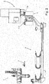
- FIG. 1 an inventive magazine 1 for tools, a tool changing device 3 and a spindle 5 of a machining system are shown in an isometric view.
- the tool changing device 3 and the spindle 5 are not part of the claimed invention, but serve to illustrate the interaction between the processing system and tool changing device 3 and the magazine 1 according to the invention for tools.
- FIG. 2 shows a view from the side of the system according to the FIG. 1 .
- the same components are provided in all figures with the same reference numerals. For the sake of clarity, not all figures are given in all figures.
- FIGS. 1 and 2 is a tool changer 7, which belongs to the tool changing device 3, shown in a "waiting position".
- the illustrated waiting position of the tool changer 7 is illustrative. In reality, two such tool changer 7 are arranged on a rotatable head of the tool changing device 3. When this head 9 in the FIG. 2 moved from the position shown on the right end of the image to the left, then reaches the tool changer 7.1 the waiting position.
- the claimed invention essentially relates to the magazine 1 and the transfer of tools between the magazine 1 and the tool changer 7, only the magazine 1 and the tool changer 7 are shown below. The rest of the tool changing device 3 and the spindle 5 of the machine tool are no longer shown for reasons of clarity.
- the magazine 1 comprises an elongated base body 11, which in the plan view is composed of a rectangle with two attached semicircles.
- a raceway 13 is arranged, which consists in the illustrated embodiment of two mutually parallel ribs 14 (see the detail X of FIG. 3 ).
- two shells or halves of the main body 11 and the ribs 14 of the raceway 13 which are arranged on them are simplified and shown in section. The interaction of the track 13 and the quivers 23 according to the invention will be explained in more detail below.
- FIG. 3 is a transfer device 15 with an unlocking device 17 and a second unlocking device 19 on the in FIG. 3 right-hand end of the magazine 1.
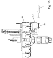
- FIG. 4 shows the magazine 1 according to the invention in an isometric view from below.
- the lower shell of the housing 11 and attached thereto (geared) motor 21 can be seen, which belongs to the drive means.
- the magazine according to the invention also includes a plurality of quivers 23, which are guided and held by means of guide elements, which are not particularly visible in these figures of the ribs 14 of the raceway 13.
- the transfer device 15 comprises an actuator, preferably a linear actuator 25, at the transfer point 26 a Segment of the raceway 13 and the quiver located in the segment 23.1 can move down from the track 13 and in the direction of the tool changer 7. at the transfer point 26, the direction of movement of the track runs from left to right.
- the direction of movement of the actuator 25 is perpendicular to it, namely from top to bottom.
- the unlocking device 17 is arranged on the movable part of the transfer device 15 and moves with this. It also includes a linear actuator 28 and an unlocking pin 29 actuated by the actuator 28.
- FIGS. 5 to 9 the transfer of a tool located in the tool changer 7 is shown and explained in a quiver 23 of the magazine 1 according to the invention in several steps.
- This waiting position is characterized in that the tool changer 7 and the tool 29 are in the immediate vicinity of the magazine 1. However, the distance is so great that a collision of a tool in one of the quiver 23 and the tool 29 in the tool changer 7 is excluded.
- FIG. 6 are opposite the FIG. 5 two changes visible.
- the tool changer 7 has moved with the tool 29 from the waiting position to a position directly below the transfer point 26.
- the unlocking device 17 has the unlocking pin 28 in the FIG. 6 from top to bottom in the quiver 23.1, which is located in the transfer area 26, but in FIG. 6 is not visible, retracted and thereby unlocks the quiver 23.1.
- the actuator 25 of the transfer device 15 is actuated, so that the quiver 23.1 and located in the transfer point 26 segment 26 of the track 13 in the FIG. 7 down in the direction of the tool changer 7 and the tool 29 are moved.
- the quiver 23.1 is no longer in a plane with the other quivers 23 of the magazine 1.
- the quiver 23.1 inverts the tool 29.
- the unlocking pin 28 is moved out of the quiver 23.1, and thereby locks the tool 29 in the quiver 23.1. This situation is in the FIG. 8 shown.
- the tool 29 can no longer fall out of the quiver 23.1, because it is held in the quiver 23.1.
- the tool changer 7 can be moved back to the waiting position (see FIG. 9 ).
- the quiver 23.1 is moved away from the transfer device 15 upwards again by the tool changer 7 until the quiver 23.1 is in one plane with the remaining quivers 23. This corresponds to the in FIG. 5 shown position of the quiver 23.
- the loading of a quiver or the transfer of a tool from the tool changer 7 to a quiver 23.1 is completed.
- the actuator 25 of the transfer device 15 moves the quiver 23.1 equipped with a tool 29 in the direction of the tool changer 7 (downward in FIG FIG. 10 ).
- the unlocking pin 28 of the unlocking device 17 is not retracted in the quiver 23.1, so that the tool 29 can not fall out of the quiver 23.1.
- FIG. 11 the same situation is shown in a view from the front.
- the tool changer moves from the waiting position in the direction of the magazine of the quiver 23.1 and takes up the tool 29.
- the unlocking device 17 is actuated and the unlocking pin 28 moves into the quiver 23.1.
- the lock between quiver 23.1 and tool 29 is opened.
- FIG. 12 shows.
- the tool changer 7 can feed the tool 29 to the spindle 5 (see FIGS. 1 and 2 ).
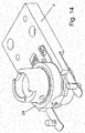
- a tool changer 7 and a tool 29 are shown in an isometric view.
- the tool changer 7 and the tool 29 belong to the periphery of the magazine according to the invention.
- the tool changer 7 is a relatively simply executed component that can receive a tool 29 by it orthogonal to the longitudinal axis of the tool 29 enters the grooves of the tool 29 and thereby holds.
- the tool is secured against falling out by means of a tool spring comprehensive leaf spring.
- This leaf spring is automatically opened and closed by the movements of the other elements involved in the change process via suitable cams at the right time, so that this no additional active functionality in the tool changer 7 must be.
- the tool change in the spindle works the same way as on the magazine side.
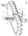
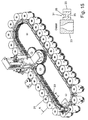
- FIGS. 15 to 19 illustrate the drive of the magazine 1 according to the invention; the upper half of the housing 11 is not shown. From the isometry according to FIG. 15 It can be clearly seen that each quiver 23 is connected to a guide element 31 and a drive element 33 in the form of a rack.
- FIG. 15 a section along the line AA through a quiver 23, a guide member 31 and a drive element 3 is shown. From this detail, it can be clearly seen that, first, the guide member 31 has two grooves 35, which is designed and dimensioned such that the ribs 14 of the raceway 13 dips into the grooves 35 of the guide element 31 and thereby guides the guide element 31 in a form-fitting manner.
- FIG. 15 In the detail of FIG. 15 is shown on the right side of the guide member 31 formed as a rack drive element 33. This toothing or extends over the entire height of the guide element 31.
- the toothing can be interrupted in the middle (not shown).
- FIG. 16 is a view from above of the exempt drive device of the magazine according to the invention 1 shown.
- the grooves 35 have a flat and a curved wall.
- the outer wall of the groove 35 is flat, or straight and the inner wall of the groove 35 is curved in a circular arc.
- the curvature of this circular arc corresponds to the radius of curvature which the raceway 13 has at the ends of the magazine.
- the thickness or the width of the groove 35 at the narrowest point corresponds to the thickness of the ribs 14 of the raceway 13.
- the straight wall of the groove 35 bears against the rib 14 of the raceway over the entire length of the guide element 31.
- the curved wall of the groove 35 touches only in the middle of the guide member 31, the rib 14 of the track 13th
- the guide element 31 bears against the rib 14 with the curved inner wall of the groove 35 over the entire length of the guide element 31.
- the outer straight wall of the groove 35 contacts the rail 14 of the raceway 13 only in the middle.
- This segment of the track 13 consists of two short sections of the ribs 14, which are connected to the transfer device 15.
- the contact points and that the guide elements 31 are curved at their ends, where they abut the adjacent guide elements 31.
- the curvature at the end faces is chosen so that it does not come to tension when the Guide elements move on the circular arc-shaped portion of the raceway 13.
- the game should always remain as small and as constant as possible in the direction of movement of the track.
- the end faces are curved in a circular arc.
- the transmission or drive motor 21 drives two coaxially arranged gears 37.1 and 37.2.
- the two gears 37.1 and 37.2 have the same number of teeth.
- the gear 37.1 drives a pinion 39.1, while the gear 37.2 a pinion 39.2 drives.
- the pinions 39.1 and 39.2 are not arranged in one plane, but axially offset from each other.
- This can be in the FIG. 17 recognize well. Namely, there meshes the pinion 39.2 with the upper part of the drive element 33 (rack segment), while the pinion 39.1 meshes with the lower part of the drive member 39.
- the gear 37.2 a plurality of concentric with the axis of rotation of the drive motor 21 arranged slots 41.
- only the gear 37.1 is rotatably connected to the output shaft of the drive motor 21.
- the second gear 37.2 is driven by the first gear 37.1.
- the torque transmission from the gear 37.1 to the gear 37.2 is non-positively by 37.2 screws (not shown) are inserted through the slots 41 of the gear, which cooperate with threaded holes (not shown) in the gear 37.1.
- the two gears 37.1 and 37.2 are clamped together in the axial direction and the required torque can be transmitted from the gear 37.1 to the gear 37.2. If you solve the screws, not shown, it is possible to rotate the gear 37.2 relative to the gear 37.1 something. As a result, the pinion 39.2 is slightly twisted.
- the drive motor 21 designed as a geared motor has a reduction which corresponds to the number of teeth of the gearwheel 37.
- the gear has a number of teeth of 50
- one revolution of the drive motor 21 clocks the magazine exactly one tooth.
- a magazine circulation can then be determined exactly and very simply according to the following formula, even if an absolute encoder on the drive motor 21 only detects the number of revolutions of the drive motor:
- a magazine circulation Number of magazine pl a ⁇ tze ⁇ Number of Z a ⁇ teeth per drive element ⁇ Unterschsverh a ⁇ ratio of the drive motor ,
- This setting or positioning of the holder 23.3 in the transfer point 24 is usually before Commissioning of the magazine 1 according to the invention. After that it is no longer necessary.
- FIG. 18 is a section of an illustrated in the magazine according to the invention, the transfer point 27 shown. It is clear that the center distances of the pinion 39.1 and 39.2 are chosen so that the teeth of the pinion 39.1 and the teeth of the pinion 39.2 offset by half a pitch are arranged to each other. This ensures that, in any case, one of the pinions 39 meshes with a drive element 33 of a quiver 23 and can drive it, even if the other pinion just dips into a gap between two adjacent drive elements 33.
Landscapes
- Engineering & Computer Science (AREA)
- Mechanical Engineering (AREA)
- Automatic Tool Replacement In Machine Tools (AREA)
Applications Claiming Priority (1)
| Application Number | Priority Date | Filing Date | Title |
|---|---|---|---|
| DE102015208642.9A DE102015208642A1 (de) | 2015-05-11 | 2015-05-11 | Magazin für Werkzeuge |
Publications (2)
| Publication Number | Publication Date |
|---|---|
| EP3093104A2 true EP3093104A2 (fr) | 2016-11-16 |
| EP3093104A3 EP3093104A3 (fr) | 2017-04-05 |
Family
ID=55970840
Family Applications (1)
| Application Number | Title | Priority Date | Filing Date |
|---|---|---|---|
| EP16168976.5A Withdrawn EP3093104A3 (fr) | 2015-05-11 | 2016-05-10 | Magasin pour outils |
Country Status (2)
| Country | Link |
|---|---|
| EP (1) | EP3093104A3 (fr) |
| DE (1) | DE102015208642A1 (fr) |
Cited By (1)
| Publication number | Priority date | Publication date | Assignee | Title |
|---|---|---|---|---|
| CN117140147A (zh) * | 2023-07-27 | 2023-12-01 | 乌本纳数控装备(浙江)有限公司 | 一种数控机床刀库刀具定位装置 |
Citations (2)
| Publication number | Priority date | Publication date | Assignee | Title |
|---|---|---|---|---|
| DE2143383A1 (de) | 1970-08-28 | 1972-03-16 | Olivetti & Co Spa | Werkzeugmaschine mit automatischem Werkzeugwechsel |
| DE19609145A1 (de) | 1996-03-08 | 1997-09-11 | Jmh Servicegesellschaft Fuer W | Einrichtung zum automatischen und/oder manuellen Werkzeugwechsel |
Family Cites Families (5)
| Publication number | Priority date | Publication date | Assignee | Title |
|---|---|---|---|---|
| CH531396A (de) * | 1970-05-29 | 1972-12-15 | Bw Weber Verwaltungs Gmbh | Werkzeugmaschine mit einer Bearbeitungseinheit zum Aufnehmen von auswechselbaren Mehrspindelköpfen |
| DE3316999A1 (de) * | 1982-08-05 | 1984-02-09 | VEB Werkzeugmaschinenkombinat "Fritz Heckert" Karl-Marx-Stadt, DDR 9030 Karl-Marx-Stadt | Vorrichtung zur speicherung von werkzeugen einer automatischen werkzeugmaschine |
| CH677204A5 (fr) * | 1988-09-02 | 1991-04-30 | Fischer Georg Fms Drehtech | |
| JP3022249B2 (ja) * | 1995-04-07 | 2000-03-15 | 豊和工業株式会社 | 工作機械のツールマガジン装置 |
| US7520847B1 (en) * | 2008-06-18 | 2009-04-21 | Campro Precision Machinery Co., Ltd. | Tool magazine of automatic tool changer |
-
2015
- 2015-05-11 DE DE102015208642.9A patent/DE102015208642A1/de not_active Withdrawn
-
2016
- 2016-05-10 EP EP16168976.5A patent/EP3093104A3/fr not_active Withdrawn
Patent Citations (2)
| Publication number | Priority date | Publication date | Assignee | Title |
|---|---|---|---|---|
| DE2143383A1 (de) | 1970-08-28 | 1972-03-16 | Olivetti & Co Spa | Werkzeugmaschine mit automatischem Werkzeugwechsel |
| DE19609145A1 (de) | 1996-03-08 | 1997-09-11 | Jmh Servicegesellschaft Fuer W | Einrichtung zum automatischen und/oder manuellen Werkzeugwechsel |
Cited By (1)
| Publication number | Priority date | Publication date | Assignee | Title |
|---|---|---|---|---|
| CN117140147A (zh) * | 2023-07-27 | 2023-12-01 | 乌本纳数控装备(浙江)有限公司 | 一种数控机床刀库刀具定位装置 |
Also Published As
| Publication number | Publication date |
|---|---|
| EP3093104A3 (fr) | 2017-04-05 |
| DE102015208642A1 (de) | 2016-11-17 |
Similar Documents
| Publication | Publication Date | Title |
|---|---|---|
| DE69703635T2 (de) | Angetriebene Verriegelungsvorrichtung für Fahrzeuge mit verbesserten Mitteln zur Begrenzung der Bewegung eines Riegels | |
| DE3730561C1 (de) | Werkzeugrevolver | |
| DE10044915B4 (de) | Spannvorrichtung, insbesondere für mehrseitig zu bearbeitende Werkstücke | |
| DE3521055C2 (de) | Vorschubvorrichtung | |
| EP0901861B1 (fr) | Outil d'ébavurage et de chanfreinage à commande centrifuge | |
| DE3817937C2 (fr) | ||
| DE3817893C2 (fr) | ||
| EP1021267A1 (fr) | Mandrin a reglage automatique des machoires et compensation de la force centrifuge | |
| DE2550599C3 (de) | Positioniereinrichtung | |
| DE1527181B1 (de) | Gewindebohrmaschine | |
| EP0352526A1 (fr) | Différentiel | |
| DE2211213C3 (de) | Vorrichtung an einer Presse zum schrittweisen Transport von Werkstücken in einem Stufenwerkzeug | |
| EP0962280A2 (fr) | Dispositif d'alignement | |
| EP0416612B1 (fr) | Tourelle revolver pour automate de tournage avec porte-outil pour outils entraînés en rotation | |
| DE4344037C1 (de) | Mehrspindel-Gewindeschneidvorrichtung | |
| DE102014217584B4 (de) | Ventiltriebvorrichtung sowie Schaltkulisse | |
| EP0585563B1 (fr) | Dispositif pour la génération d'un mouvement synchrone de translation/rotation | |
| DE102010036184B4 (de) | Presse | |
| EP3093104A2 (fr) | Magasin pour outils | |
| DE3245260A1 (de) | Doppelnocken-teilgetriebe | |
| EP2895869A1 (fr) | Dispositif d'entraînement individuel ou en bloc combiné, en particulier pour canaux de pipetage | |
| EP0208891A2 (fr) | Machine d'assemblage | |
| DE19858980C1 (de) | Fahrzeugsitz, insbesondere Kraftfahrzeugsitz, mit einer Einstellvorrichtung | |
| DE3153388C2 (fr) | ||
| DE3301334C2 (fr) |
Legal Events
| Date | Code | Title | Description |
|---|---|---|---|
| PUAI | Public reference made under article 153(3) epc to a published international application that has entered the european phase |
Free format text: ORIGINAL CODE: 0009012 |
|
| AK | Designated contracting states |
Kind code of ref document: A2 Designated state(s): AL AT BE BG CH CY CZ DE DK EE ES FI FR GB GR HR HU IE IS IT LI LT LU LV MC MK MT NL NO PL PT RO RS SE SI SK SM TR |
|
| AX | Request for extension of the european patent |
Extension state: BA ME |
|
| RIC1 | Information provided on ipc code assigned before grant |
Ipc: B23Q 3/155 20060101AFI20161117BHEP Ipc: B23Q 3/157 20060101ALI20161117BHEP |
|
| PUAL | Search report despatched |
Free format text: ORIGINAL CODE: 0009013 |
|
| AK | Designated contracting states |
Kind code of ref document: A3 Designated state(s): AL AT BE BG CH CY CZ DE DK EE ES FI FR GB GR HR HU IE IS IT LI LT LU LV MC MK MT NL NO PL PT RO RS SE SI SK SM TR |
|
| AX | Request for extension of the european patent |
Extension state: BA ME |
|
| RIC1 | Information provided on ipc code assigned before grant |
Ipc: B23Q 3/155 20060101AFI20170227BHEP Ipc: B23Q 3/157 20060101ALI20170227BHEP |
|
| STAA | Information on the status of an ep patent application or granted ep patent |
Free format text: STATUS: THE APPLICATION IS DEEMED TO BE WITHDRAWN |
|
| 18D | Application deemed to be withdrawn |
Effective date: 20171006 |