EP3093123B1 - Procédé de fabrication d'une structure tridimensionnelle - Google Patents
Procédé de fabrication d'une structure tridimensionnelle Download PDFInfo
- Publication number
- EP3093123B1 EP3093123B1 EP16163538.8A EP16163538A EP3093123B1 EP 3093123 B1 EP3093123 B1 EP 3093123B1 EP 16163538 A EP16163538 A EP 16163538A EP 3093123 B1 EP3093123 B1 EP 3093123B1
- Authority
- EP
- European Patent Office
- Prior art keywords
- partial structures
- enveloping
- interfaces
- writing
- overall structure
- Prior art date
- Legal status (The legal status is an assumption and is not a legal conclusion. Google has not performed a legal analysis and makes no representation as to the accuracy of the status listed.)
- Active
Links
Images

Classifications
-
- G—PHYSICS
- G05—CONTROLLING; REGULATING
- G05B—CONTROL OR REGULATING SYSTEMS IN GENERAL; FUNCTIONAL ELEMENTS OF SUCH SYSTEMS; MONITORING OR TESTING ARRANGEMENTS FOR SUCH SYSTEMS OR ELEMENTS
- G05B19/00—Program-control systems
- G05B19/02—Program-control systems electric
- G05B19/18—Numerical control [NC], i.e. automatically operating machines, in particular machine tools, e.g. in a manufacturing environment, so as to execute positioning, movement or co-ordinated operations by means of program data in numerical form
- G05B19/4097—Numerical control [NC], i.e. automatically operating machines, in particular machine tools, e.g. in a manufacturing environment, so as to execute positioning, movement or co-ordinated operations by means of program data in numerical form characterised by using design data to control NC machines, e.g. CAD/CAM
- G05B19/4099—Surface or curve machining, making three-dimensional [3D] objects, e.g. desktop manufacturing
-
- G—PHYSICS
- G06—COMPUTING OR CALCULATING; COUNTING
- G06F—ELECTRIC DIGITAL DATA PROCESSING
- G06F30/00—Computer-aided design [CAD]
- G06F30/10—Geometric CAD
- G06F30/13—Architectural design, e.g. computer-aided architectural design [CAAD] related to design of buildings, bridges, landscapes, production plants or roads
-
- B—PERFORMING OPERATIONS; TRANSPORTING
- B33—ADDITIVE MANUFACTURING TECHNOLOGY
- B33Y—ADDITIVE MANUFACTURING, i.e. MANUFACTURING OF THREE-DIMENSIONAL [3D] OBJECTS BY ADDITIVE DEPOSITION, ADDITIVE AGGLOMERATION OR ADDITIVE LAYERING, e.g. BY 3D PRINTING, STEREOLITHOGRAPHY OR SELECTIVE LASER SINTERING
- B33Y10/00—Processes of additive manufacturing
-
- B—PERFORMING OPERATIONS; TRANSPORTING
- B29—WORKING OF PLASTICS; WORKING OF SUBSTANCES IN A PLASTIC STATE IN GENERAL
- B29C—SHAPING OR JOINING OF PLASTICS; SHAPING OF MATERIAL IN A PLASTIC STATE, NOT OTHERWISE PROVIDED FOR; AFTER-TREATMENT OF THE SHAPED PRODUCTS, e.g. REPAIRING
- B29C64/00—Additive manufacturing, i.e. manufacturing of three-dimensional [3D] objects by additive deposition, additive agglomeration or additive layering, e.g. by 3D printing, stereolithography or selective laser sintering
- B29C64/10—Processes of additive manufacturing
- B29C64/106—Processes of additive manufacturing using only liquids or viscous materials, e.g. depositing a continuous bead of viscous material
- B29C64/124—Processes of additive manufacturing using only liquids or viscous materials, e.g. depositing a continuous bead of viscous material using layers of liquid which are selectively solidified
- B29C64/129—Processes of additive manufacturing using only liquids or viscous materials, e.g. depositing a continuous bead of viscous material using layers of liquid which are selectively solidified characterised by the energy source therefor, e.g. by global irradiation combined with a mask
- B29C64/135—Processes of additive manufacturing using only liquids or viscous materials, e.g. depositing a continuous bead of viscous material using layers of liquid which are selectively solidified characterised by the energy source therefor, e.g. by global irradiation combined with a mask the energy source being concentrated, e.g. scanning lasers or focused light sources
-
- B—PERFORMING OPERATIONS; TRANSPORTING
- B29—WORKING OF PLASTICS; WORKING OF SUBSTANCES IN A PLASTIC STATE IN GENERAL
- B29C—SHAPING OR JOINING OF PLASTICS; SHAPING OF MATERIAL IN A PLASTIC STATE, NOT OTHERWISE PROVIDED FOR; AFTER-TREATMENT OF THE SHAPED PRODUCTS, e.g. REPAIRING
- B29C64/00—Additive manufacturing, i.e. manufacturing of three-dimensional [3D] objects by additive deposition, additive agglomeration or additive layering, e.g. by 3D printing, stereolithography or selective laser sintering
- B29C64/20—Apparatus for additive manufacturing; Details thereof or accessories therefor
- B29C64/264—Arrangements for irradiation
- B29C64/277—Arrangements for irradiation using multiple radiation means, e.g. micromirrors or multiple light-emitting diodes [LED]
-
- B—PERFORMING OPERATIONS; TRANSPORTING
- B33—ADDITIVE MANUFACTURING TECHNOLOGY
- B33Y—ADDITIVE MANUFACTURING, i.e. MANUFACTURING OF THREE-DIMENSIONAL [3D] OBJECTS BY ADDITIVE DEPOSITION, ADDITIVE AGGLOMERATION OR ADDITIVE LAYERING, e.g. BY 3D PRINTING, STEREOLITHOGRAPHY OR SELECTIVE LASER SINTERING
- B33Y80/00—Products made by additive manufacturing
-
- G—PHYSICS
- G05—CONTROLLING; REGULATING
- G05B—CONTROL OR REGULATING SYSTEMS IN GENERAL; FUNCTIONAL ELEMENTS OF SUCH SYSTEMS; MONITORING OR TESTING ARRANGEMENTS FOR SUCH SYSTEMS OR ELEMENTS
- G05B2219/00—Program-control systems
- G05B2219/30—Nc systems
- G05B2219/35—Nc in input of data, input till input file format
- G05B2219/35134—3-D cad-cam
-
- G—PHYSICS
- G05—CONTROLLING; REGULATING
- G05B—CONTROL OR REGULATING SYSTEMS IN GENERAL; FUNCTIONAL ELEMENTS OF SUCH SYSTEMS; MONITORING OR TESTING ARRANGEMENTS FOR SUCH SYSTEMS OR ELEMENTS
- G05B2219/00—Program-control systems
- G05B2219/30—Nc systems
- G05B2219/49—Nc machine tool, till multiple
- G05B2219/49007—Making, forming 3-D object, model, surface
Definitions
- the invention relates to a method for producing a three-dimensional structure according to the preamble of claim 1.
- Such patterning methods find particular use in the production of micro- or nanostructures, prototypes (e.g., so-called “rapid prototyping"), or in the production of workpieces with special molding requirements, e.g. for experimental purposes as well as in areas where great freedom of design is desired.
- This structuring device is often used, which have a predetermined main direction of the structural entry.
- the main direction is dictated by the design, e.g. by the preferred direction of a structuring electron beam, by the optical axis of a laser optics, by the direction of a material build-up beam of a 3D printer, or by the mechanical axis of a machining tool that can be controlled in three spatial directions.
- the structuring device also has a design-limited writing area. Only in this limited space area can structuring or structural entry take place.
- the specified write area is often smaller than the total forest to be produced. Therefore, in so-called "stitching method", the entire structure is decomposed into a plurality of sub-structures, which match the writing area of the structuring device and are written successively.
- Stereolithography methods are known wherein a desired structure of block-like substructures or layers in a bath of liquid lithographic material (eg a photopolymer) is built up by targeted exposure to a writing beam.
- the writing beam polymerizes by local exposure in each case structural blocks in a layer on the surface of the bath of lithographic material having a desired pattern.
- stepwise lowering a carrier substrate in the bath of lithographic material the structure is then built up in layers.
- a layer building method with the features of the preamble of claim 1 is in the EP 2 565 018 A1 described.
- the invention is based, to increase the reliability and quality of the structuring with the shortest possible process times the task.
- the structuring is carried out by means of a structuring device, which is designed to carry out structuring in a generally structurally prescribed writing area around a predetermined main direction of the structural entry.
- the overall structure is defined by sequentially defining a plurality of substructures that complement each other in their entirety, wherein the sequentially written substructures are respectively delimited by enveloping boundary surfaces or cut out of the overall structure by the enveloping boundary surfaces.
- the partial structures are selected such that the enveloping boundary surfaces are inclined to the main direction of the structural entry, i. are not parallel to the main direction or include a non-vanishing angle with the main direction.
- the substructures that complement the overall structure can lie next to each other in a flat area and / or can lie one above the other like a layer.
- the main direction of the structural entry is the direction or axis along which the structuring device essentially acts to define the structuring in the writing area.
- the structuring can be carried out, for example, in a suitable base material (eg lithographic lacquer).
- a lithographic device has a writing beam, which acts around an optical axis such that the optical axis forms the main direction of the structuring device designed as a lithographic device.
- the writing beam may be, for example, a laser beam.
- the production of the total structure is carried out by means of an energy irradiation method in a crosslinkable or polymerizable by energy input lithography material.
- the desired three-dimensional structure is thereby defined in the lithographic material by controlled and localized polymerization by means of the energy beam and solidified and / or exposed by an optionally subsequent development step.
- the lithography material is solidifiable by the energy input.
- solid lithographic materials can be used from the beginning, which are polymerized by the energy input and the structuring is exposed in a subsequent development step.
- the lithography material in its unpolymerized state is preferably liquid, viscous, gel or solid.
- a lithographic varnish, in particular a negative varnish is used.
- the polymerization of the lithography material takes place in a focus region of a writing beam of a radiation source of the structuring device spatially displaceable within the writing area.
- the structuring device is preferably a laser lithograph, electron beam lithograph or the like.
- a plurality of write beams may act in the write area, the focus areas of which jointly carry out the structuring.
- the substructures are in particular determined by the fact that the entire structure is divided into the substructures and each substructure is enveloped directly by the boundary surface.
- the enveloping interfaces are insofar in particular imaginary auxiliary surfaces for defining the substructures.
- the substructure is defined as a section of the forest bordered by the interfaces.
- the enveloping boundary surfaces of the substructure run obliquely to the main direction of the structure entry, so that occlusion of the structural entry along the main direction by already existing substructures is avoided. It is therefore possible to choose a comparatively large depth along the main direction for the substructure. Therefore, for the production of the entire structure, a decomposition into only a comparatively small number of partial structure blocks is necessary. This enables significantly shorter computation times for the decomposition of the overall structure into substructures and shorter process times for writing the substructures, without impairing the structural quality and reliability of the structure production. Also, the lifetime of the structuring device can be increased since the required number of structuring operations can be reduced overall.
- an interface runs which delimits this substructure in the direction opposite to already existing substructures such that the outside of the substructure not adjacent to already existing substructures is visible without shading, starting from the structuring device.
- the substructures it is conceivable, in particular, for the substructures to be sequentially written sequentially along a decomposition row, wherein the selected substructure runs in the direction opposite to the already existing substructures delimiting boundary surface such that the outside of the substructure formed by this boundary surface faces the structuring device.
- the surface normal of a substructure opposite to already existing substructures bounding boundary surface (ie the outside) outside of the substructure, starting from the considered outside extends only to the structuring and not away from this.
- the lithography material is preferably formed in such a way and the radiation source of the writing beam is preferably matched to the lithography material such that a polymerization is possible only by means of the two-photon absorption or the multi-photon absorption.
- the wavelength of the write beam chosen so large (and thus the associated quantum energy to be so low) that the required for the polymerization energy input only by simultaneous absorption of two or more quanta is reached. The probability of such an absorption process is intensity-dependent and significantly increased compared to the rest of the writing beam in the focus area.
- the substructures are defined by decomposing the overall structure by intersecting the enveloping interfaces.
- the enveloping boundary surfaces are preferably flat or composed of flat sections, which allows a computationally simple disassembly.
- the enveloping boundary surfaces have curved sections or are curved.
- the decomposition of the overall structure into substructures preferably takes place by software.
- a data record representing the overall structure for example CAD data
- CAD data for example CAD data
- further data sets are computationally determined, which represent the substructures, the structuring device being driven in accordance with the data records.
- the data sets of the substructures are determined computer-assisted by sections of the overall structure with the enveloping boundary surfaces.
- the software is a complete, non-overlapping decomposition of the overall structure in the substructures.
- the decomposition preferably takes place in such a way that adjacent substructures touch along at least one enveloping boundary surface.
- a complete decomposition into partial structures takes place.
- adjacent substructures may each have at least one identical enveloping interface.
- the substructures are determined such that the enveloping boundary surfaces, and in particular all possible tangent planes over the entire course of the enveloping boundary surfaces, with the Main direction of the structural entry include an acute angle which is open against the main device of the structural entry or which is open to the structuring device.
- the enveloping boundary surfaces are in particular aligned such that the outside defined by an interface surface of a substructure of the structuring device faces at an acute angle.
- angles greater than 0 ° and less than 45 °, preferably between 5 ° and 20 °, for example in the range of 15 °, have proved to be advantageous.
- the substructures are preferably arranged in a decomposition grid and are written sequentially one after the other, wherein in each case at least one enveloping boundary surface of a substructure runs parallel to at least one or more enveloping boundary surface of other substructures in the decomposition grid.
- the enveloping boundary surfaces of the partial structures which supplement the overall structure run in pairs in parallel to one another.
- the writing area of the structuring device is sequentially displaced and positioned, whereby a substructure is written in each case after relocation and positioning in the writing field.
- either the structuring device or a substrate can be displaced relative to the structuring device.
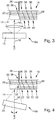
- a first type structuring device 10a is shown, in which by means of a projection device 12, a writing beam 14 is emitted through a corresponding aperture around a main direction 16 in the main direction 16.
- the writing beam 14 has, for example, a spatial intensity variation, which is designed to define the desired structure.
- the desired structure is in the FIGS. 1 to 4 generally designated by reference numeral 18 (total structure).
- the structuring device 10 by design, has a spatially limited writing area 20, within which structuring can take place, for example by means of the writing beam 14 (FIG. FIG. 1 ).
- the writing beam is irradiated by way of example in a non-illustrated bath of lithographic material which is polymerizable and solidifiable by means of the writing beam 14.
- the overall structure is decomposed into a plurality of partial structures 22, which in the examples according to FIG Figures 1 and 2 are block-shaped and bordered by enveloping interfaces 24, which in the case of Figures 1 and 2 extend parallel to the main direction 16.
- the substructures 22 are written sequentially one after the other, for example in a decomposition grid of juxtaposed subregions 22.
- the writing area 20 is displaced sequentially, for example by means of a positioning device 26 relative to the substrate Structuring device 10 is moved.
- a substructure 22 for example, in turn, in each case be constructed sequentially from layers 28, as in the FIGS. 1 to 4 indicated.
- the addressed substrate can be shifted stepwise along the main direction 16.
- the writing beam 14 has a non-vanishing beam angle due to the aperture, portions of already written substructures 22 can cause shading of regions 30 in substructures 22 to be written in each case to lead. This shading in the areas 30 leads to faulty structures.
- FIG. 2 shows a different method of structuring, in which a focus area 32 of the writing beam can be controlled by means of a beam guiding device 34 (for example tilting mirror) in the writing area 20 and moved.
- a beam guiding device 34 for example tilting mirror
- a second type structuring device 10b is provided.
- a scanning method is used.
- each of the successively written substructures 22 can in turn be constructed sequentially from layers 28.
- FIGS. 3 and 4 Method according to the invention for producing the three-dimensional structure 18 will be explained, with structuring devices 10a (corresponding to FIG. 1 ) and / or 10b (corresponding to FIG. 2 ) be used. Therefore, regarding the features of the structuring devices 10a and 10b, reference is made to the description of FIGS Figures 1 and 2 Referenced.
- a plurality of partial structures 22 are defined sequentially by means of the writing beam 14.
- Each substructure 22 is bounded by enveloping interfaces 36.
- the overall structure 18 is completely decomposed into partial structures 22, in particular in such a way that adjacent partial structures 22 each have a common enveloping boundary surface 36.
- the enveloping interfaces run in contrast to the Figures 1 and 2 not parallel to the main direction 16 of the structural entry, but are oriented obliquely to the main direction 16.
- all enveloping boundary surfaces 36 are substantially parallel to each other and have an angle to the main direction 16 which is equal to or greater than the beam angle of the write beam 14 (in which case the angle enclosed between main direction 16 and boundary surface 36 and opening in the direction opposite to the main direction 16 is looked at).
- the boundary surfaces 36 each of which delimits the substructures 22 to be written sequentially, run obliquely to the main direction 16.
- the boundary surfaces 36 may in particular also have more complex configurations than simple planes, for example sections adjoining one another, differently inclined planes and / or sections extending in a curved manner (cf. FIG. 4 ). It is also decisive here that because of the (locally) inclined course of the boundary surfaces 36 to the main direction 16, shading by means of already existing partial structures 22 within the writing area 20 is avoided.
- the enveloping boundary surfaces 36 each extend in such a way that the line of sight of each section of the writing area 20 against the main direction 16 is unshaded.
- the boundary surfaces 36 for the substructures 22 each form outer sides 38 of the already existing substructures 22, which completely face a viewing point P which is at a distance from the main direction 16 and are freely visible from this.
Landscapes
- Engineering & Computer Science (AREA)
- Chemical & Material Sciences (AREA)
- Materials Engineering (AREA)
- Physics & Mathematics (AREA)
- Manufacturing & Machinery (AREA)
- Optics & Photonics (AREA)
- Mechanical Engineering (AREA)
- Health & Medical Sciences (AREA)
- Toxicology (AREA)
- General Physics & Mathematics (AREA)
- Geometry (AREA)
- Microelectronics & Electronic Packaging (AREA)
- Computer Hardware Design (AREA)
- Theoretical Computer Science (AREA)
- Human Computer Interaction (AREA)
- Automation & Control Theory (AREA)
- Structural Engineering (AREA)
- General Engineering & Computer Science (AREA)
- Evolutionary Computation (AREA)
- Pure & Applied Mathematics (AREA)
- Mathematical Optimization (AREA)
- Mathematical Analysis (AREA)
- Computational Mathematics (AREA)
- Civil Engineering (AREA)
- Architecture (AREA)
Claims (7)
- Procédé de production d'une structure tridimensionnelle brute (18) grâce à un procédé d'irradiation d'énergie dans un matériau lithographique polymérisable par apport d'énergie, faisant appel à un dispositif de structuration (10a, 10b) qui, dans une région d'écriture (20), présente une direction principale (16) prédéfinie de la trame structurelle,
dans lequel la structure brute (18) est définie en ce qu'une pluralité de sous-structures (22) complémentaires de la structure brute (18) sont définies de manière séquentielle, dans lequel les sous-structures (22) sont respectivement délimitées à l'intérieur de surfaces limites enveloppantes (36), dans lequel les sous-structures (22) sont définies de telle manière que les surfaces limites enveloppantes (36) s'étendent obliquement par rapport à la direction principale (16) de la trame structurelle,
dans lequel la polymérisation du matériau lithographique a lieu dans au moins une région focale (32), pouvant être déplacée spatialement au sein de la région d'écriture (20), d'au moins un faisceau d'écriture (14),
caractérisé en ce que la polymérisation du matériau lithographique a lieu dans la région focale (32) par absorption à deux photons ou par absorption à plus de deux photons,
et en ce que la surface limite, qui délimite une sous-structure (22) à définir nouvellement respective dans la direction opposée à celle de sous-structures (22) déjà existantes, s'étend respectivement de telle manière que ladite surface limite (36) forme un côté extérieur (38) des sous-structures déjà existantes et le côté extérieur (38) est complètement visible depuis un point de vue (P) situé à distance dans une direction opposée à la direction principale (16). - Procédé selon la revendication 1, caractérisé en ce que les sous-structures (22) sont délimitées par des sections de la structure brute (18) comprenant les surfaces limites enveloppantes (36).
- Procédé selon l'une quelconque des revendications précédentes, caractérisé en ce qu'un ensemble de données représentant la structure brute (18) est prévu, et en ce que d'autres ensembles de données qui représentent les sous-structures (22) sont déterminés par calcul à partir de celui-ci, dans lequel le dispositif de structuration (10a, 10b) est commandé conformément aux ensembles de données.
- Procédé selon l'une quelconque des revendications précédentes, caractérisé en ce que des sous-structures (22) adjacentes présentent respectivement au moins une surface limite enveloppante (36) identique.
- Procédé selon l'une quelconque des revendications précédentes, caractérisé en ce que les surfaces limites enveloppantes (36) font avec la direction principale (16) de la trame structurelle un angle aigu qui est ouvert dans une direction opposée à la direction principale (16) .
- Procédé selon l'une quelconque des revendications précédentes, caractérisé en ce que les sous-structures (22) sont agencées selon une grille de dispersion et respectivement au moins une surface limite (36) d'une sous-structure (22) s'étend parallèlement à au moins une surface limite enveloppante (36) d'une autre sous-structure (22).
- Procédé selon l'une quelconque des revendications précédentes, caractérisé en ce que la région d'écriture (20) du dispositif de structuration (10a, 10b) est déplacée de manière séquentielle en vue d'une définition séquentielle des sous-structures (22) et une sous-structure (22) est respectivement écrite dans le champ d'écriture (20).
Applications Claiming Priority (1)
| Application Number | Priority Date | Filing Date | Title |
|---|---|---|---|
| DE102015208852.9A DE102015208852A1 (de) | 2015-05-13 | 2015-05-13 | Verfahren zum Herstellen einer dreidimensionalen Struktur |
Publications (2)
| Publication Number | Publication Date |
|---|---|
| EP3093123A1 EP3093123A1 (fr) | 2016-11-16 |
| EP3093123B1 true EP3093123B1 (fr) | 2019-06-19 |
Family
ID=55802177
Family Applications (1)
| Application Number | Title | Priority Date | Filing Date |
|---|---|---|---|
| EP16163538.8A Active EP3093123B1 (fr) | 2015-05-13 | 2016-04-01 | Procédé de fabrication d'une structure tridimensionnelle |
Country Status (5)
| Country | Link |
|---|---|
| US (1) | US10118376B2 (fr) |
| EP (1) | EP3093123B1 (fr) |
| JP (1) | JP6808349B2 (fr) |
| CN (1) | CN106156399B (fr) |
| DE (1) | DE102015208852A1 (fr) |
Families Citing this family (8)
| Publication number | Priority date | Publication date | Assignee | Title |
|---|---|---|---|---|
| DE102017108031B4 (de) * | 2017-04-13 | 2023-07-27 | GEFERTEC GmbH | Verfahren und Fertigungsvorrichtung zum lagenweisen Aufbau eines durch Geometriebeschreibungsdaten definierten Formkörpers |
| DE102017110241A1 (de) * | 2017-05-11 | 2018-11-15 | Nanoscribe Gmbh | Verfahren zum Erzeugen einer 3D-Struktur mittels Laserlithographie sowie Computerprogrammprodukt |
| US10413167B2 (en) | 2017-05-30 | 2019-09-17 | Synaptive Medical (Barbados) Inc. | Micro-optical surgical probes and micro-optical probe tips and methods of manufacture therefor |
| JP7010308B2 (ja) * | 2018-01-31 | 2022-01-26 | 株式会社ニコン | 処理装置及び処理方法 |
| EP3702132B1 (fr) | 2019-02-26 | 2023-01-11 | UpNano GmbH | Procédé de fabrication générative par lithographie de composants tridimensionnels |
| US11484969B2 (en) | 2019-10-18 | 2022-11-01 | 3M Innovative Properties Company | Method of making a three-dimensional structure containing substructures |
| CN113021881A (zh) * | 2021-03-12 | 2021-06-25 | 湖南华曙高科技有限责任公司 | 一种复杂桁架结构制件的成型方法、成型设备及可读存储介质 |
| CN114083639B (zh) * | 2022-01-20 | 2022-04-29 | 中交第一公路勘察设计研究院有限公司 | 面向混凝土3d打印的平面路径拟合方法及系统 |
Family Cites Families (16)
| Publication number | Priority date | Publication date | Assignee | Title |
|---|---|---|---|---|
| US4575330A (en) | 1984-08-08 | 1986-03-11 | Uvp, Inc. | Apparatus for production of three-dimensional objects by stereolithography |
| US5198159A (en) * | 1990-10-09 | 1993-03-30 | Matsushita Electric Works, Ltd. | Process of fabricating three-dimensional objects from a light curable resin liquid |
| DE4102260A1 (de) * | 1991-01-23 | 1992-07-30 | Artos Med Produkte | Vorrichtung zur herstellung beliebig geformter koerper |
| US5247180A (en) | 1991-12-30 | 1993-09-21 | Texas Instruments Incorporated | Stereolithographic apparatus and method of use |
| US6500378B1 (en) * | 2000-07-13 | 2002-12-31 | Eom Technologies, L.L.C. | Method and apparatus for creating three-dimensional objects by cross-sectional lithography |
| US6841340B2 (en) * | 2001-07-13 | 2005-01-11 | Fuji Photo Film Co., Ltd. | Optical fabricating method and apparatus |
| DE10207564C1 (de) * | 2002-02-22 | 2003-11-20 | Fraunhofer Ges Forschung | Vorrichtung zur Lichtlenkung aus wenigstens einem teiltransluzentem Flächenmaterial |
| US8676735B1 (en) * | 2002-11-11 | 2014-03-18 | Zxibix, Inc. | System and method to facilitate and document user thinking about an arbitrary problem with collaboration system |
| AT503027B1 (de) * | 2006-05-08 | 2007-07-15 | Austria Tech & System Tech | Leiterplattenelement mit optoelektronischem bauelement und licht-wellenleiter |
| JP4916392B2 (ja) * | 2007-06-26 | 2012-04-11 | パナソニック株式会社 | 三次元形状造形物の製造方法及び製造装置 |
| KR100950311B1 (ko) * | 2007-11-06 | 2010-03-31 | 포항공과대학교 산학협력단 | 소수성 외부 표면을 갖는 3차원 형상 구조물의 제조방법 |
| EP2232531B1 (fr) * | 2007-12-12 | 2018-09-19 | 3M Innovative Properties Company | Procédé de fabrication de structures présentant une définition de bordure améliorée |
| KR101209003B1 (ko) * | 2010-10-14 | 2012-12-06 | 주식회사 유진테크 | 3차원 구조의 메모리 소자를 제조하는 방법 및 장치 |
| EP2565018B1 (fr) * | 2011-08-31 | 2020-12-30 | Fit Ag | Modèle de données pour décrire un composant à fabriquer à l'aide d'un procédé de fabrication additive |
| JP2013067088A (ja) * | 2011-09-22 | 2013-04-18 | Tokyo Kogei Univ | 光造形法、造形物 |
| JP2016085547A (ja) * | 2014-10-24 | 2016-05-19 | 株式会社東芝 | 電子機器および方法 |
-
2015
- 2015-05-13 DE DE102015208852.9A patent/DE102015208852A1/de not_active Ceased
-
2016
- 2016-04-01 EP EP16163538.8A patent/EP3093123B1/fr active Active
- 2016-04-28 US US15/140,898 patent/US10118376B2/en active Active
- 2016-05-12 CN CN201610317574.0A patent/CN106156399B/zh active Active
- 2016-05-12 JP JP2016096231A patent/JP6808349B2/ja active Active
Non-Patent Citations (1)
| Title |
|---|
| None * |
Also Published As
| Publication number | Publication date |
|---|---|
| CN106156399B (zh) | 2021-07-23 |
| DE102015208852A1 (de) | 2016-11-17 |
| JP6808349B2 (ja) | 2021-01-06 |
| EP3093123A1 (fr) | 2016-11-16 |
| JP2016210189A (ja) | 2016-12-15 |
| US20160332365A1 (en) | 2016-11-17 |
| CN106156399A (zh) | 2016-11-23 |
| US10118376B2 (en) | 2018-11-06 |
Similar Documents
| Publication | Publication Date | Title |
|---|---|---|
| EP3093123B1 (fr) | Procédé de fabrication d'une structure tridimensionnelle | |
| EP3970900B1 (fr) | Procédé de génération d'une structure 3d par lithographie laser à dose d'exposition modifiée au niveau des sections de bord, ainsi que produit-programme informatique correspondant | |
| DE102014221480B4 (de) | Verfahren zum Herstellen einer dreidimensionalen Struktur | |
| EP3022044B1 (fr) | Procédé et dispositif de fabrication d'un objet en trois dimensions ainsi que système de génération de masques d'exposition | |
| DE102015100731A1 (de) | Optische formvorrichtung und optisches formverfahren | |
| DE102017126624A1 (de) | Schichtselektive belichtung im überhangbereich bei der generativen fertigung | |
| EP3362835B1 (fr) | Optique d'exposition et dispositif de fabrication d'un objet tridimensionnel | |
| DE102016209933A1 (de) | Vorrichtung und Verfahren zum generativen Herstellen eines dreidimensionalen Objekts | |
| EP3372385B1 (fr) | Dispositif d'exposition pour un dispositif de fabrication additive d'objets tridimensionnels | |
| DE102015219866A1 (de) | Vorrichtung und Verfahren zum Herstellen eines dreidimensionalen Objekts | |
| WO2018172079A1 (fr) | Optimisation de chevauchement | |
| DE102015225300A1 (de) | Verfahren und Anordnungen zur Verringerung der Grenzflächenadhäsion bei der Photopolymerisation | |
| EP4127785B1 (fr) | Procédé de fabrication d'un élément optique diffractif continu et élément optique diffractif continu | |
| DE102018127451A1 (de) | Vorrichtung sowie Verfahren zur additiven Herstellung eines Bauteils | |
| DE102015226523A1 (de) | Belichtungsvorrichtung, Vorrichtung und Verfahren zum Herstellen eines dreidimensionalen Objekts | |
| DE202014010855U1 (de) | Digitales Codieren von Gummiartikeln | |
| EP4043186A1 (fr) | Procédé et dispositif de commande d'un dispositif de fabrication additive à base de lithographie | |
| DE10305427B4 (de) | Herstellungsverfahren für eine Lochscheibe zum Ausstoßen eines Fluids | |
| DE202014011007U1 (de) | Digitales Codieren von Gummiartikeln | |
| EP3702132B1 (fr) | Procédé de fabrication générative par lithographie de composants tridimensionnels | |
| DE102012109130A1 (de) | Verfahren und Vorrichtungen zur Herstellung dreidimensionaler Strukturen | |
| DE102020126432A1 (de) | Verfahren zur herstellung eines bauelements und bauelement | |
| DE102005003218B4 (de) | Vorrichtung und Verfahren zum Herstellen eines dreidimensionalen Gegenstandes mittels Stereolithographie | |
| EP3967510A1 (fr) | Document de sécurité pourvu de marque de sûreté en fonction du sens d'observation | |
| DE102004059233A1 (de) | Halbleiterbauelement und Verfahren zum Herstellen einer optischen Struktur aus definierten optisch durchlässigen Bereichen und definierten opaken Bereichen in einer Umhüllung eines Halbleiterbauelements |
Legal Events
| Date | Code | Title | Description |
|---|---|---|---|
| PUAI | Public reference made under article 153(3) epc to a published international application that has entered the european phase |
Free format text: ORIGINAL CODE: 0009012 |
|
| AK | Designated contracting states |
Kind code of ref document: A1 Designated state(s): AL AT BE BG CH CY CZ DE DK EE ES FI FR GB GR HR HU IE IS IT LI LT LU LV MC MK MT NL NO PL PT RO RS SE SI SK SM TR |
|
| AX | Request for extension of the european patent |
Extension state: BA ME |
|
| STAA | Information on the status of an ep patent application or granted ep patent |
Free format text: STATUS: REQUEST FOR EXAMINATION WAS MADE |
|
| 17P | Request for examination filed |
Effective date: 20170515 |
|
| RBV | Designated contracting states (corrected) |
Designated state(s): AL AT BE BG CH CY CZ DE DK EE ES FI FR GB GR HR HU IE IS IT LI LT LU LV MC MK MT NL NO PL PT RO RS SE SI SK SM TR |
|
| REG | Reference to a national code |
Ref country code: DE Ref legal event code: R079 Ref document number: 502016005107 Country of ref document: DE Free format text: PREVIOUS MAIN CLASS: B29C0067000000 Ipc: B33Y0080000000 |
|
| RIC1 | Information provided on ipc code assigned before grant |
Ipc: B33Y 80/00 20150101AFI20180914BHEP Ipc: B29C 64/135 20170101ALI20180914BHEP Ipc: B29C 64/277 20170101ALI20180914BHEP |
|
| GRAP | Despatch of communication of intention to grant a patent |
Free format text: ORIGINAL CODE: EPIDOSNIGR1 |
|
| STAA | Information on the status of an ep patent application or granted ep patent |
Free format text: STATUS: GRANT OF PATENT IS INTENDED |
|
| RIN1 | Information on inventor provided before grant (corrected) |
Inventor name: TANGUY, YANN Inventor name: HOFFMANN, JOERG Inventor name: REINER, ROMAN REINHARD |
|
| INTG | Intention to grant announced |
Effective date: 20181030 |
|
| GRAJ | Information related to disapproval of communication of intention to grant by the applicant or resumption of examination proceedings by the epo deleted |
Free format text: ORIGINAL CODE: EPIDOSDIGR1 |
|
| STAA | Information on the status of an ep patent application or granted ep patent |
Free format text: STATUS: REQUEST FOR EXAMINATION WAS MADE |
|
| GRAP | Despatch of communication of intention to grant a patent |
Free format text: ORIGINAL CODE: EPIDOSNIGR1 |
|
| STAA | Information on the status of an ep patent application or granted ep patent |
Free format text: STATUS: GRANT OF PATENT IS INTENDED |
|
| INTC | Intention to grant announced (deleted) | ||
| INTG | Intention to grant announced |
Effective date: 20190108 |
|
| RIC1 | Information provided on ipc code assigned before grant |
Ipc: B29C 64/277 20170101ALI20180914BHEP Ipc: B33Y 80/00 20150101AFI20180914BHEP Ipc: B29C 64/135 20170101ALI20180914BHEP |
|
| GRAS | Grant fee paid |
Free format text: ORIGINAL CODE: EPIDOSNIGR3 |
|
| GRAA | (expected) grant |
Free format text: ORIGINAL CODE: 0009210 |
|
| STAA | Information on the status of an ep patent application or granted ep patent |
Free format text: STATUS: THE PATENT HAS BEEN GRANTED |
|
| AK | Designated contracting states |
Kind code of ref document: B1 Designated state(s): AL AT BE BG CH CY CZ DE DK EE ES FI FR GB GR HR HU IE IS IT LI LT LU LV MC MK MT NL NO PL PT RO RS SE SI SK SM TR |
|
| REG | Reference to a national code |
Ref country code: GB Ref legal event code: FG4D Free format text: NOT ENGLISH |
|
| REG | Reference to a national code |
Ref country code: CH Ref legal event code: EP Ref country code: CH Ref legal event code: NV Representative=s name: DREISS PATENTANWAELTE PARTG MBB, DE |
|
| REG | Reference to a national code |
Ref country code: IE Ref legal event code: FG4D Free format text: LANGUAGE OF EP DOCUMENT: GERMAN |
|
| REG | Reference to a national code |
Ref country code: AT Ref legal event code: REF Ref document number: 1144954 Country of ref document: AT Kind code of ref document: T Effective date: 20190715 |
|
| REG | Reference to a national code |
Ref country code: DE Ref legal event code: R096 Ref document number: 502016005107 Country of ref document: DE |
|
| REG | Reference to a national code |
Ref country code: NL Ref legal event code: MP Effective date: 20190619 |
|
| PG25 | Lapsed in a contracting state [announced via postgrant information from national office to epo] |
Ref country code: NO Free format text: LAPSE BECAUSE OF FAILURE TO SUBMIT A TRANSLATION OF THE DESCRIPTION OR TO PAY THE FEE WITHIN THE PRESCRIBED TIME-LIMIT Effective date: 20190919 Ref country code: FI Free format text: LAPSE BECAUSE OF FAILURE TO SUBMIT A TRANSLATION OF THE DESCRIPTION OR TO PAY THE FEE WITHIN THE PRESCRIBED TIME-LIMIT Effective date: 20190619 Ref country code: LT Free format text: LAPSE BECAUSE OF FAILURE TO SUBMIT A TRANSLATION OF THE DESCRIPTION OR TO PAY THE FEE WITHIN THE PRESCRIBED TIME-LIMIT Effective date: 20190619 Ref country code: HR Free format text: LAPSE BECAUSE OF FAILURE TO SUBMIT A TRANSLATION OF THE DESCRIPTION OR TO PAY THE FEE WITHIN THE PRESCRIBED TIME-LIMIT Effective date: 20190619 Ref country code: SE Free format text: LAPSE BECAUSE OF FAILURE TO SUBMIT A TRANSLATION OF THE DESCRIPTION OR TO PAY THE FEE WITHIN THE PRESCRIBED TIME-LIMIT Effective date: 20190619 Ref country code: AL Free format text: LAPSE BECAUSE OF FAILURE TO SUBMIT A TRANSLATION OF THE DESCRIPTION OR TO PAY THE FEE WITHIN THE PRESCRIBED TIME-LIMIT Effective date: 20190619 |
|
| REG | Reference to a national code |
Ref country code: LT Ref legal event code: MG4D |
|
| PG25 | Lapsed in a contracting state [announced via postgrant information from national office to epo] |
Ref country code: RS Free format text: LAPSE BECAUSE OF FAILURE TO SUBMIT A TRANSLATION OF THE DESCRIPTION OR TO PAY THE FEE WITHIN THE PRESCRIBED TIME-LIMIT Effective date: 20190619 Ref country code: LV Free format text: LAPSE BECAUSE OF FAILURE TO SUBMIT A TRANSLATION OF THE DESCRIPTION OR TO PAY THE FEE WITHIN THE PRESCRIBED TIME-LIMIT Effective date: 20190619 Ref country code: BG Free format text: LAPSE BECAUSE OF FAILURE TO SUBMIT A TRANSLATION OF THE DESCRIPTION OR TO PAY THE FEE WITHIN THE PRESCRIBED TIME-LIMIT Effective date: 20190919 Ref country code: GR Free format text: LAPSE BECAUSE OF FAILURE TO SUBMIT A TRANSLATION OF THE DESCRIPTION OR TO PAY THE FEE WITHIN THE PRESCRIBED TIME-LIMIT Effective date: 20190920 |
|
| PG25 | Lapsed in a contracting state [announced via postgrant information from national office to epo] |
Ref country code: SK Free format text: LAPSE BECAUSE OF FAILURE TO SUBMIT A TRANSLATION OF THE DESCRIPTION OR TO PAY THE FEE WITHIN THE PRESCRIBED TIME-LIMIT Effective date: 20190619 Ref country code: RO Free format text: LAPSE BECAUSE OF FAILURE TO SUBMIT A TRANSLATION OF THE DESCRIPTION OR TO PAY THE FEE WITHIN THE PRESCRIBED TIME-LIMIT Effective date: 20190619 Ref country code: CZ Free format text: LAPSE BECAUSE OF FAILURE TO SUBMIT A TRANSLATION OF THE DESCRIPTION OR TO PAY THE FEE WITHIN THE PRESCRIBED TIME-LIMIT Effective date: 20190619 Ref country code: NL Free format text: LAPSE BECAUSE OF FAILURE TO SUBMIT A TRANSLATION OF THE DESCRIPTION OR TO PAY THE FEE WITHIN THE PRESCRIBED TIME-LIMIT Effective date: 20190619 Ref country code: PT Free format text: LAPSE BECAUSE OF FAILURE TO SUBMIT A TRANSLATION OF THE DESCRIPTION OR TO PAY THE FEE WITHIN THE PRESCRIBED TIME-LIMIT Effective date: 20191021 Ref country code: EE Free format text: LAPSE BECAUSE OF FAILURE TO SUBMIT A TRANSLATION OF THE DESCRIPTION OR TO PAY THE FEE WITHIN THE PRESCRIBED TIME-LIMIT Effective date: 20190619 |
|
| PG25 | Lapsed in a contracting state [announced via postgrant information from national office to epo] |
Ref country code: IT Free format text: LAPSE BECAUSE OF FAILURE TO SUBMIT A TRANSLATION OF THE DESCRIPTION OR TO PAY THE FEE WITHIN THE PRESCRIBED TIME-LIMIT Effective date: 20190619 Ref country code: SM Free format text: LAPSE BECAUSE OF FAILURE TO SUBMIT A TRANSLATION OF THE DESCRIPTION OR TO PAY THE FEE WITHIN THE PRESCRIBED TIME-LIMIT Effective date: 20190619 Ref country code: IS Free format text: LAPSE BECAUSE OF FAILURE TO SUBMIT A TRANSLATION OF THE DESCRIPTION OR TO PAY THE FEE WITHIN THE PRESCRIBED TIME-LIMIT Effective date: 20191019 Ref country code: ES Free format text: LAPSE BECAUSE OF FAILURE TO SUBMIT A TRANSLATION OF THE DESCRIPTION OR TO PAY THE FEE WITHIN THE PRESCRIBED TIME-LIMIT Effective date: 20190619 |
|
| PG25 | Lapsed in a contracting state [announced via postgrant information from national office to epo] |
Ref country code: TR Free format text: LAPSE BECAUSE OF FAILURE TO SUBMIT A TRANSLATION OF THE DESCRIPTION OR TO PAY THE FEE WITHIN THE PRESCRIBED TIME-LIMIT Effective date: 20190619 |
|
| PG25 | Lapsed in a contracting state [announced via postgrant information from national office to epo] |
Ref country code: PL Free format text: LAPSE BECAUSE OF FAILURE TO SUBMIT A TRANSLATION OF THE DESCRIPTION OR TO PAY THE FEE WITHIN THE PRESCRIBED TIME-LIMIT Effective date: 20190619 Ref country code: DK Free format text: LAPSE BECAUSE OF FAILURE TO SUBMIT A TRANSLATION OF THE DESCRIPTION OR TO PAY THE FEE WITHIN THE PRESCRIBED TIME-LIMIT Effective date: 20190619 |
|
| PG25 | Lapsed in a contracting state [announced via postgrant information from national office to epo] |
Ref country code: IS Free format text: LAPSE BECAUSE OF FAILURE TO SUBMIT A TRANSLATION OF THE DESCRIPTION OR TO PAY THE FEE WITHIN THE PRESCRIBED TIME-LIMIT Effective date: 20200224 |
|
| REG | Reference to a national code |
Ref country code: DE Ref legal event code: R097 Ref document number: 502016005107 Country of ref document: DE |
|
| PLBE | No opposition filed within time limit |
Free format text: ORIGINAL CODE: 0009261 |
|
| STAA | Information on the status of an ep patent application or granted ep patent |
Free format text: STATUS: NO OPPOSITION FILED WITHIN TIME LIMIT |
|
| PG2D | Information on lapse in contracting state deleted |
Ref country code: IS |
|
| 26N | No opposition filed |
Effective date: 20200603 |
|
| PG25 | Lapsed in a contracting state [announced via postgrant information from national office to epo] |
Ref country code: SI Free format text: LAPSE BECAUSE OF FAILURE TO SUBMIT A TRANSLATION OF THE DESCRIPTION OR TO PAY THE FEE WITHIN THE PRESCRIBED TIME-LIMIT Effective date: 20190619 |
|
| PG25 | Lapsed in a contracting state [announced via postgrant information from national office to epo] |
Ref country code: MC Free format text: LAPSE BECAUSE OF FAILURE TO SUBMIT A TRANSLATION OF THE DESCRIPTION OR TO PAY THE FEE WITHIN THE PRESCRIBED TIME-LIMIT Effective date: 20190619 |
|
| PG25 | Lapsed in a contracting state [announced via postgrant information from national office to epo] |
Ref country code: LU Free format text: LAPSE BECAUSE OF NON-PAYMENT OF DUE FEES Effective date: 20200401 |
|
| REG | Reference to a national code |
Ref country code: BE Ref legal event code: MM Effective date: 20200430 |
|
| PG25 | Lapsed in a contracting state [announced via postgrant information from national office to epo] |
Ref country code: BE Free format text: LAPSE BECAUSE OF NON-PAYMENT OF DUE FEES Effective date: 20200430 |
|
| REG | Reference to a national code |
Ref country code: DE Ref legal event code: R082 Ref document number: 502016005107 Country of ref document: DE Representative=s name: DREISS PATENTANWAELTE PARTG MBB, DE Ref country code: DE Ref legal event code: R081 Ref document number: 502016005107 Country of ref document: DE Owner name: NANOSCRIBE HOLDING GMBH, DE Free format text: FORMER OWNER: NANOSCRIBE GMBH, 76344 EGGENSTEIN-LEOPOLDSHAFEN, DE |
|
| PG25 | Lapsed in a contracting state [announced via postgrant information from national office to epo] |
Ref country code: IE Free format text: LAPSE BECAUSE OF NON-PAYMENT OF DUE FEES Effective date: 20200401 |
|
| PG25 | Lapsed in a contracting state [announced via postgrant information from national office to epo] |
Ref country code: MT Free format text: LAPSE BECAUSE OF FAILURE TO SUBMIT A TRANSLATION OF THE DESCRIPTION OR TO PAY THE FEE WITHIN THE PRESCRIBED TIME-LIMIT Effective date: 20190619 Ref country code: CY Free format text: LAPSE BECAUSE OF FAILURE TO SUBMIT A TRANSLATION OF THE DESCRIPTION OR TO PAY THE FEE WITHIN THE PRESCRIBED TIME-LIMIT Effective date: 20190619 |
|
| REG | Reference to a national code |
Ref country code: AT Ref legal event code: MM01 Ref document number: 1144954 Country of ref document: AT Kind code of ref document: T Effective date: 20210401 |
|
| PG25 | Lapsed in a contracting state [announced via postgrant information from national office to epo] |
Ref country code: MK Free format text: LAPSE BECAUSE OF FAILURE TO SUBMIT A TRANSLATION OF THE DESCRIPTION OR TO PAY THE FEE WITHIN THE PRESCRIBED TIME-LIMIT Effective date: 20190619 |
|
| PG25 | Lapsed in a contracting state [announced via postgrant information from national office to epo] |
Ref country code: AT Free format text: LAPSE BECAUSE OF NON-PAYMENT OF DUE FEES Effective date: 20210401 |
|
| P01 | Opt-out of the competence of the unified patent court (upc) registered |
Effective date: 20230504 |
|
| PGFP | Annual fee paid to national office [announced via postgrant information from national office to epo] |
Ref country code: DE Payment date: 20250417 Year of fee payment: 10 |
|
| PGFP | Annual fee paid to national office [announced via postgrant information from national office to epo] |
Ref country code: FR Payment date: 20250425 Year of fee payment: 10 |
|
| PGFP | Annual fee paid to national office [announced via postgrant information from national office to epo] |
Ref country code: CH Payment date: 20250501 Year of fee payment: 10 |
|
| PGFP | Annual fee paid to national office [announced via postgrant information from national office to epo] |
Ref country code: GB Payment date: 20260324 Year of fee payment: 11 |