EP3093206B1 - Surveillance centrale d'une installation d'alimentation en air pour vehicules sur rails - Google Patents
Surveillance centrale d'une installation d'alimentation en air pour vehicules sur rails Download PDFInfo
- Publication number
- EP3093206B1 EP3093206B1 EP16001030.2A EP16001030A EP3093206B1 EP 3093206 B1 EP3093206 B1 EP 3093206B1 EP 16001030 A EP16001030 A EP 16001030A EP 3093206 B1 EP3093206 B1 EP 3093206B1
- Authority
- EP
- European Patent Office
- Prior art keywords
- air supply
- supply system
- compressor
- rail vehicle
- monitoring
- Prior art date
- Legal status (The legal status is an assumption and is not a legal conclusion. Google has not performed a legal analysis and makes no representation as to the accuracy of the status listed.)
- Active
Links
Images

Classifications
-
- F—MECHANICAL ENGINEERING; LIGHTING; HEATING; WEAPONS; BLASTING
- F04—POSITIVE - DISPLACEMENT MACHINES FOR LIQUIDS; PUMPS FOR LIQUIDS OR ELASTIC FLUIDS
- F04B—POSITIVE-DISPLACEMENT MACHINES FOR LIQUIDS; PUMPS
- F04B49/00—Control, e.g. of pump delivery, or pump pressure of, or safety measures for, machines, pumps, or pumping installations, not otherwise provided for, or of interest apart from, groups F04B1/00 - F04B47/00
- F04B49/06—Control using electricity
- F04B49/065—Control using electricity and making use of computers
-
- B—PERFORMING OPERATIONS; TRANSPORTING
- B60—VEHICLES IN GENERAL
- B60T—VEHICLE BRAKE CONTROL SYSTEMS OR PARTS THEREOF; BRAKE CONTROL SYSTEMS OR PARTS THEREOF, IN GENERAL; ARRANGEMENT OF BRAKING ELEMENTS ON VEHICLES IN GENERAL; PORTABLE DEVICES FOR PREVENTING UNWANTED MOVEMENT OF VEHICLES; VEHICLE MODIFICATIONS TO FACILITATE COOLING OF BRAKES
- B60T13/00—Transmitting braking action from initiating means to ultimate brake actuator with power assistance or drive; Brake systems incorporating such transmitting means, e.g. air-pressure brake systems
- B60T13/10—Transmitting braking action from initiating means to ultimate brake actuator with power assistance or drive; Brake systems incorporating such transmitting means, e.g. air-pressure brake systems with fluid assistance, drive, or release
- B60T13/66—Electrical control in fluid-pressure brake systems
- B60T13/665—Electrical control in fluid-pressure brake systems the systems being specially adapted for transferring two or more command signals, e.g. railway systems
-
- B—PERFORMING OPERATIONS; TRANSPORTING
- B60—VEHICLES IN GENERAL
- B60T—VEHICLE BRAKE CONTROL SYSTEMS OR PARTS THEREOF; BRAKE CONTROL SYSTEMS OR PARTS THEREOF, IN GENERAL; ARRANGEMENT OF BRAKING ELEMENTS ON VEHICLES IN GENERAL; PORTABLE DEVICES FOR PREVENTING UNWANTED MOVEMENT OF VEHICLES; VEHICLE MODIFICATIONS TO FACILITATE COOLING OF BRAKES
- B60T17/00—Component parts, details, or accessories of power brake systems not covered by groups B60T8/00, B60T13/00 or B60T15/00, or presenting other characteristic features
- B60T17/02—Arrangements of pumps or compressors, or control devices therefor
-
- B—PERFORMING OPERATIONS; TRANSPORTING
- B60—VEHICLES IN GENERAL
- B60T—VEHICLE BRAKE CONTROL SYSTEMS OR PARTS THEREOF; BRAKE CONTROL SYSTEMS OR PARTS THEREOF, IN GENERAL; ARRANGEMENT OF BRAKING ELEMENTS ON VEHICLES IN GENERAL; PORTABLE DEVICES FOR PREVENTING UNWANTED MOVEMENT OF VEHICLES; VEHICLE MODIFICATIONS TO FACILITATE COOLING OF BRAKES
- B60T17/00—Component parts, details, or accessories of power brake systems not covered by groups B60T8/00, B60T13/00 or B60T15/00, or presenting other characteristic features
- B60T17/18—Safety devices; Monitoring
- B60T17/22—Devices for monitoring or checking brake systems; Signal devices
- B60T17/228—Devices for monitoring or checking brake systems; Signal devices for railway vehicles
-
- B—PERFORMING OPERATIONS; TRANSPORTING
- B61—RAILWAYS
- B61C—LOCOMOTIVES; MOTOR RAILCARS
- B61C17/00—Arrangement or disposition of parts; Details or accessories not otherwise provided for; Use of control gear and control systems
-
- F—MECHANICAL ENGINEERING; LIGHTING; HEATING; WEAPONS; BLASTING
- F04—POSITIVE - DISPLACEMENT MACHINES FOR LIQUIDS; PUMPS FOR LIQUIDS OR ELASTIC FLUIDS
- F04B—POSITIVE-DISPLACEMENT MACHINES FOR LIQUIDS; PUMPS
- F04B51/00—Testing machines, pumps, or pumping installations
Definitions
- the present invention relates to an apparatus and a method for monitoring an air supply system in a rail vehicle.
- the invention also relates to a computer program with code means for carrying out the steps of the aforementioned method on a computer system, and a computer-readable storage medium on which a program code having the code means of the computer program is stored.
- the operator purchases an air supply system when purchasing the rail vehicle and is responsible for operation and maintenance.
- Existing plants include, for example, a compressor and an air dryer and, depending on the system principle, an auxiliary converter and an electric motor with electric drive, a hydraulic clutch and a hydraulic motor with hydraulic drive, a mechanical flange connection with direct drive by a diesel engine of the vehicle, or a mechanical Clutch, a gearbox, a belt drive or similar when driven by an engine of the vehicle.
- FIG. 10 shows the DE 10 2013 101 502 A1 an air supply system with electronic converter, one of a motor driven compressor for generating compressed air, an electronic converter for demand-driven compressor control, and a plurality of analog and / or digital sensors for generating electrical measuring signals are provided.
- the electrical measurement signals can be used to control the electrical converter and to monitor and control the compressor, wherein processing of the measurement signals generated by the sensors takes place in the electronic converter to bus signals, which can be provided for evaluation at a bus interface.
- separate control devices for electronic monitoring of the compressor and the engine can be saved and a possibility can be intelligently coupled with other diagnostic and control signals of the inverter, further processing and advantageous operating states by communication among the controllers of the rail vehicle for the compressor and / or or to provide the air supply system.
- US 2013/297163 A1 discloses an apparatus and a method for monitoring an air supply system of a rail vehicle according to the preambles of claims 1 and 8, respectively.
- US 2008/219866 A1 discloses an apparatus and method for generating and controlling an air flow rate.
- the present invention is therefore based on the object to provide improved transparency about the operating behavior, the state and the technical availability of the air supply systems of rail vehicles.
- a rail vehicle may be provided for operation on a rail.
- the rail vehicle may have one or more cars and / or towing vehicles.
- a wagon of a rail vehicle can be a railcar, which has its own drive.
- a control device for controlling a brake system of the rail vehicle can be implemented as software, hardware or a combination of software and hardware.
- the controller may be implemented as one or more modules and / or processes and / or objects and / or threads.
- a brake system of a rail vehicle may generally have a plurality of brakes, which operate on different principles. Such brakes may include, for example, friction brakes, dynamic brakes, rail brakes or other brakes such as aerodynamic brakes.
- the air supply system of a rail vehicle is thus monitored by means of a device having the features of claim 1.
- the invention also relates to a monitoring system having the features of claim 4 and a system having the features of claim 7.
- the invention further relates to a method having the features of claim 8
- the invention relates to a computer-readable storage medium having the features of claim 11.
- the invention relates to a computer program with code means according to claim 12.
- an air supply system which offers technical possibilities to automatically measure the delivered or recorded power, automatically transfer data obtained from it via an intelligent interface to a stationary evaluation unit, automatically derive the condition and the availability from this, automatically from the system as required Calculate output power and automatically initiate maintenance and overhaul intervals or identify optimization potential for operation.
- the proposed solution measures allow continuous monitoring of the operating state and the reliability of the air supply system, so that a possible trouble-free operation of the air supply system and early detection of a possible need for maintenance or avoidance of unnecessary maintenance measures can be achieved.
- the operating behavior for the specific application in each vehicle can be recorded and optimized and for early Detection of quality issues. This can also be used to identify current and future system requirements for deriving better-matched developments and innovations.
- the device is designed to determine the power or energy absorbed by the air supply system from an electrical energy supplied to a motor for driving a compressor.
- the device is designed to determine the power or energy output by the air supply system from an air stream discharged from the compressor or an air dryer downstream of the compressor.
- the device may be configured to determine an actual operational readiness duration of the air supply system based on the received measurement data from an operating hours counter.
- the device may have an additional data interface to a vehicle control of the rail vehicle and be configured to read out vehicle-specific data of the rail vehicle and to provide it via the communication interface.
- the plurality of measuring devices may include an electric energy meter and a tachometer for an engine of the air supply system, and a gas meter or a gas anemometer for a compressor or an air dryer of the air supply system.
- the multitude of measuring devices preferably comprise an operating hours counter for the compressor.
- the step of transmitting the information to the stationary evaluation unit may be in response to the detection of a trigger signal.
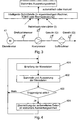
- Fig. 1 shows a schematic block diagram of a monitoring system for an air supply system according to a first embodiment with a compressor 43 which is driven by means of an electric motor 42.
- the compressor 43 is associated with a downstream air dryer 44 for dehumidifying the generated compressed air.
- the electric motor 42 may be, for example, a three-phase motor and the compressor 43, for example, a single-stage screw compressor.
- the air dryer installation 44 can, for example, operate according to the adsorption drying principle.
- the electric motor 42 and the compressor 43 may be arranged, for example, within a metallic capsule (not shown).
- the upstream electronic inverter 45 provides as input converter (auxiliary converter) for the adaptation of the input voltage to the requirements of the electric motor 42.
- An energy meter 31 is used to measure the electrical power to the electric motor 42
- a tachometer 32 is used to measure the speed of the electric motor 42
- a Operating hours counter 33 is used to measure the operating hours of the compressor 43.
- a gas meter 34 for measuring the air consumption on the input side and / or the output side of the air dryer 44 is provided.
- the electric energy meter 31 may be disposed in front of the inverter 41 or between the inverter 41 and the electric motor 42.
- the gas meter 34 or a gas anemometer may be arranged after the compressor 43 and / or after the air dryer 44.
- the tachometer 32 may be mounted on a shaft between the electric motor 42 and the compressor 43.
- the measurement data obtained by the aforementioned measuring devices 31-34 are collected and processed via an internal interface provided by an intelligent interface 20 and then transmitted either automatically or manually via a provided by the intelligent interface 20 communication interface to a not arranged in the rail vehicle, stationary evaluation unit 10.
- An “intelligent interface” is to be understood as meaning a software-controlled processor environment which serves to control the monitoring of the air supply system. In particular, it may be configured to generate automatic reports of occurring errors or irregularities in addition to the extraction and transmission of performance-related data.
- the intelligent interface can be implemented in a separate computer unit or also in the computer of a vehicle control, not shown, (for example, the Train Control and Management System (TCMS)) or in the brake control computer.
- TCMS Train Control and Management System
- the intelligent interface 20 can additionally have a data interface to a vehicle control (TCMS) in order to automatically read out vehicle data (for example identification features, etc.), which makes possible a vehicle-specific evaluation of the measured data obtained at the stationary evaluation unit 10.
- vehicle data for example identification features, etc.
- data from the intelligent interface 20 can also be made available to the vehicle computer.
- the data transmission via the communication interface to the remote stationary evaluation unit 10 can, for example, be wireless or wired (via overhead line or rail system) via a serial connection or a local or public network.
- This error messages for example. Under Using the Simple Network Management Protocol (SNMP).
- SNMP Simple Network Management Protocol
- the intelligent interface 20 can also operate independently of an operating system used in the air supply system and thus also enable monitoring without an installed or running operating system.
- the intelligent interface 20 can have a central controller, to which further, remote controllers for special purposes, such as the monitoring of special sensors or functions of the air supply system, can be connected.
- the connection between the central controller and the decentralized controllers can take place via a bus system, such as, for example, the so-called Intelligent Platform Management Bus (IPMB).
- IPMB Intelligent Platform Management Bus
- the time period during which the air supply system is available in principle ready for operation can also be recorded. The determination of this time period can be made by technical means (for example by appropriate software control) in the intelligent interface 20.
- Fig. 2 shows a schematic block diagram of an alternative monitoring system for an air supply system according to a second embodiment in hydraulic drive of the compressor 43 by means of a hydraulic motor 46 and a hydraulic clutch.
- the hydraulic motor 46 is fed via a suitable electrical power supply 45.
- Fig. 2 shows a schematic block diagram of an alternative monitoring system for an air supply system according to a second embodiment in hydraulic drive of the compressor 43 by means of a hydraulic motor 46 and a hydraulic clutch.
- the hydraulic motor 46 is fed via a suitable electrical power supply 45.
- the speed of the compressor 43 may alternatively be measured with a tachometer.
- Fig. 3 shows a schematic block diagram of another alternative monitoring system for an air supply system according to a third embodiment with direct drive of the compressor 43 by a diesel engine 47 of the vehicle by means of flange connection.
- the components of the block diagram correspond to FIG Fig. 3 those of the block diagram Fig. 1 so that again a description can be dispensed with.
- the acquired monitoring data may also be transmitted online from the smart interface 20 via the communication interface (e.g., via a standard OPC interface architecture) or may be initially stored digitally in a data logger.
- OPC Unified Architecture is a communication protocol used for machine-to-machine communication. As the newest of all OPC specifications, OPC UA differs significantly from its predecessors, in particular in its ability to acquire machine data (process values, measured values, Parameter etc.) not only to transport, but also to describe machine-readable semantically.
- the OPC information model is a so-called full-mesh network of nodes (so-called "nodes"), with which, in addition to the user data of a node, meta and diagnostic information are also represented.
- a node is similar to an object from object-oriented programming. It also supports events that can be sent to exchange certain information between devices.
- the datalogger consists of a programmable microprocessor, a storage medium, at least one interface, and one or more channels for connecting the data source, such as a data logger. the measuring devices 31-34.
- the measured data are passed on from the respective measuring device or sensor directly via an internal interface to the data logger and stored.
- the internal interface can be an interface according to the standard RS232, CAN or USB.
- the memory cycle for the data logger may depend on the specific use.
- the storage process can take place at exact time intervals or at the moment of data generation.
- the data can then be transmitted from the intelligent interface 20 directly to the stationary evaluation unit 10 via corresponding industrial interfaces and / or software tools forming the communication interface. There, the received data and / or messages of the intelligent interface 20 can be used directly, for example, to display online the current state of the air supply system.
- Fig. 4 shows a flowchart of a monitoring method according to a fourth embodiment, which can be implemented as software in the intelligent interface 20, for example.
- step 401 After the program has started, in step 401, first of all, the measurement data is received by the measuring devices 31-34, for example in accordance with the specifications of the used measurement interface protocol of the internal interface. Thereafter, the received measurement data is collected and evaluated in step 402. Now, in step 403, a wait is made until a manually or automatically activated trigger signal is detected.
- the trigger signal can be triggered, for example, by the external stationary evaluation unit 10 or the air supply system or another control device of the rail vehicle at predetermined time intervals or by in response to a predetermined event. As long as no active trigger signal is detected, the process returns to step 401, receives further measurement data in step 401 and evaluates it in step 402.
- step 403 the flow advances to step 404 and the data prepared since the last transmission is transmitted via the communication station to the stationary evaluation unit 10 where it is then used for monitoring, optimization and / or maintenance purposes or the like. be used.
- the monitoring by means of the intelligent interface 10 can be realized by a program-controlled computer device, in which the steps of the Fig. 4 and also the extraction, evaluation and transmission of the measurement or evaluation result data are controlled by means of a computer program which is stored for example on a computer-readable storage medium or can be downloaded via a network such as the Internet or a local area network.
Landscapes
- Engineering & Computer Science (AREA)
- Mechanical Engineering (AREA)
- Transportation (AREA)
- General Engineering & Computer Science (AREA)
- Automation & Control Theory (AREA)
- Computer Hardware Design (AREA)
- Valves And Accessory Devices For Braking Systems (AREA)
- Vehicle Cleaning, Maintenance, Repair, Refitting, And Outriggers (AREA)
- Electric Propulsion And Braking For Vehicles (AREA)
Claims (12)
- Dispositif (20) de contrôle d'une installation (41; 45; 47, 42; 46, 43, 44) d'alimentation en air d'un véhicule sur rail, le système (20) comprenant :- une interface interne pour recevoir, d'une pluralité d'appareils (31 à 34) de mesure, des données de mesure, qui dépendent de la puissance, de l'installation d'alimentation en air;- un dispositif (402) d'exploitation pour exploiter les données de mesure reçues et pour déterminer une information sur une puissance ou une énergie reçue ou cédée par l'installation d'alimentation en air et- une interface de communication pour transmettre l'information du véhicule sur rail à une unité (10) d'exploitation fixe,caractérisé en ce quele dispositif (20) détermine la puissance ou l'énergie reçue par l'installation d'alimentation en air, à partir d'une énergie électrique envoyée à un moteur (42; 46; 47) d'entraînement d'un compresseur (43) etle dispositif (20) détermine la puissance ou l'énergie cédée par l'installation d'alimentation en air, à partir d'un courant d'air donné par le compresseur (43) ou par un sécheur (44) d'air, monté en aval du compresseur (43).
- Dispositif suivant la revendication 1, dans lequel
le dispositif (20) est conformé pour, à l'aide des données de mesure reçues, déterminer par un compteur (33) d'heures de fonctionnement, une durée réelle de disponibilité de fonctionnement de l'installation d'alimentation en air. - Dispositif suivant l'une des revendications précédentes, dans lequel
le dispositif (20) a une interface supplémentaire de données avec une commande du véhicule sur rail et est conformé pour lire des données spécifiques au véhicule du véhicule sur rail et les mettre à disposition par l'interface de communication. - Système de contrôle d'une installation d'alimentation en air d'un véhicule sur rail, le système de contrôle ayant un dispositif (20) suivant l'une des revendications 1 à 3 et une pluralité d'appareil (31 à 34) de mesure pour obtenir les données de mesure, qui dépendent de la puissance.
- Système de contrôle suivant la revendication 4, dans lequel la pluralité d'appareils de mesure comprend un compteur (31) d'énergie électrique et un appareil (32) de mesure du régime d'un moteur (42) de l'installation d'alimentation en air et un compteur (34) de gaz pour un compresseur (43) ou pour un sécheur (44) d'air de l'installation d'alimentation en air.
- Système de contrôle suivant la revendication 5, dans lequel la pluralité d'appareils de mesure comprend un compteur (33) d'heures de fonctionnement du compresseur (43).
- Système constitué d'un dispositif (10) fixe de contrôle d'une installation d'alimentation en air d'un véhicule sur rail et le système de contrôle suivant l'une des revendications 4 à 6, le dispositif (10) fixe comprenant :- un dispositif pour recevoir, par l'interface de communication du véhicule ferroviaire, une information sur la puissance ou l'énergie reçue ou cédée par l'installation d'alimentation en air et- un dispositif d'exploitation pour exploiter l'information reçue et pour en déduire une information d'entretien ou d'optimisation de l'installation d'alimentation en air.
- Procédé de contrôle d'une installation d'alimentation en air d'un véhicule sur rail, comprenant les stades :- réception de valeurs de mesure qui dépendent de la puissance de l'installation d'alimentation en air d'une pluralité d'appareils (31 à 34) de mesure;- exploitation des valeurs de mesure reçues et détermination d'une information sur la puissance ou l'énergie reçue ou cédée par l'installation d'alimentation en air et- transmission de l'information du véhicule sur rail à une unité (10) d'exploitation fixe,caractérisé parla détermination d'une puissance ou d'une énergie reçue par l'installation de l'alimentation en air, à partir d'une énergie électrique envoyée à un moteur (42; 46; 47) d'entraînement d'un compresseur etla détermination d'une puissance ou d'une énergie reçue par l'installation d'alimentation en air, à partir d'un courant d'air donné par le compresseur (43) ou par un sécheur (44) d'air monté en aval du compresseur (43).
- Procédé suivant la revendication 8, dans lequel le stade de la transmission de l'information s'effectue en réaction à la détection d'un signal de déclenchement.
- Procédé suivant la revendication 8 ou 9, comprenant en outre les stades supplémentaires de l'exploitation de l'information transmise dans l'unité (10) de l'exploitation fixe et de la déduction d'une information d'entretien ou d'optimisation de l'installation d'alimentation en air, à partir de l'information transmise et exploitée.
- Support de mémoire déchiffrable par ordinateur, sur lequel, est mémorisé un code de programme, qui peut être réalisé sur un système d'ordinateur et qui, lors de sa réalisation, produit les stades de l'une des revendications 8 à 10 de procédé.
- Programme d'ordinateur ayant des moyens de code, qui, lorsqu'ils sont réalisés sur un système d'ordinateur, produisent les stades de l'une des revendications 8 à 10 de procédé.
Priority Applications (1)
| Application Number | Priority Date | Filing Date | Title |
|---|---|---|---|
| PL16001030T PL3093206T3 (pl) | 2015-05-13 | 2016-05-06 | Centralne monitorowanie systemu zasilania powietrzem dla pojazdów szynowych |
Applications Claiming Priority (1)
| Application Number | Priority Date | Filing Date | Title |
|---|---|---|---|
| DE102015107552.0A DE102015107552A1 (de) | 2015-05-13 | 2015-05-13 | Zentrale Überwachung einer Luftversorgungsanlage für Schienenfahrzeuge |
Publications (2)
| Publication Number | Publication Date |
|---|---|
| EP3093206A1 EP3093206A1 (fr) | 2016-11-16 |
| EP3093206B1 true EP3093206B1 (fr) | 2017-12-27 |
Family
ID=55970748
Family Applications (1)
| Application Number | Title | Priority Date | Filing Date |
|---|---|---|---|
| EP16001030.2A Active EP3093206B1 (fr) | 2015-05-13 | 2016-05-06 | Surveillance centrale d'une installation d'alimentation en air pour vehicules sur rails |
Country Status (5)
| Country | Link |
|---|---|
| EP (1) | EP3093206B1 (fr) |
| DE (1) | DE102015107552A1 (fr) |
| ES (1) | ES2696929T3 (fr) |
| PL (1) | PL3093206T3 (fr) |
| TR (1) | TR201802722T4 (fr) |
Cited By (1)
| Publication number | Priority date | Publication date | Assignee | Title |
|---|---|---|---|---|
| WO2020173649A1 (fr) | 2019-02-25 | 2020-09-03 | Knorr-Bremse Systeme für Schienenfahrzeuge GmbH | Système d'alimentation en air et procédé de commande et/ou de surveillance d'un système d'alimentation en air |
Families Citing this family (4)
| Publication number | Priority date | Publication date | Assignee | Title |
|---|---|---|---|---|
| DE102018215108B4 (de) | 2018-09-05 | 2026-03-05 | Knorr-Bremse Systeme für Schienenfahrzeuge GmbH | System zur Diagnose und Überwachung von Luftversorgungsanlagen und deren Komponenten |
| DE102019108066A1 (de) * | 2019-03-28 | 2020-10-01 | Knorr-Bremse Systeme für Schienenfahrzeuge GmbH | System zum Bereitstellen und/oder Überwachen von Betriebsdaten einer Druckluftversorgung, Druckluftversorgung und Verfahren zum Bereitstellen von Betriebsdaten und/oder zum Überwachen der Funktionsfähigkeit einer Druckluftversorgung |
| RU2729907C1 (ru) * | 2019-12-16 | 2020-08-13 | Федеральное государственное бюджетное образовательное учреждение высшего образования Иркутский государственный университет путей сообщения (ФГБОУ ВО ИрГУПС) | Способ диагностики и контроля тормозной сети поезда |
| JP7691389B2 (ja) * | 2022-03-07 | 2025-06-11 | 株式会社日立製作所 | 故障予兆診断装置及び故障予兆診断方法 |
Family Cites Families (10)
| Publication number | Priority date | Publication date | Assignee | Title |
|---|---|---|---|---|
| US5845272A (en) * | 1996-11-29 | 1998-12-01 | General Electric Company | System and method for isolating failures in a locomotive |
| US6301531B1 (en) * | 1999-08-23 | 2001-10-09 | General Electric Company | Vehicle maintenance management system and method |
| DE10142790B4 (de) * | 2001-08-31 | 2007-01-18 | Winkle, Günther, Dipl.-Ing.(TU) | Bremsdiagnose für Schienen- und Straßenfahrzeuge |
| US6993675B2 (en) * | 2002-07-31 | 2006-01-31 | General Electric Company | Method and system for monitoring problem resolution of a machine |
| DE20308045U1 (de) * | 2003-05-22 | 2003-08-28 | Bauer Kompressoren GmbH, 81477 München | Kabelloses Betriebsüberwachungsgerät |
| US8781671B2 (en) * | 2005-06-09 | 2014-07-15 | New York Air Brake Corporation | On-board brake system diagnostic and reporting system |
| WO2008095129A2 (fr) * | 2007-01-31 | 2008-08-07 | Turbodyne Technologies, Inc. | Génération et gestion de débit d'air massique |
| US8260494B2 (en) * | 2008-04-02 | 2012-09-04 | International Truck Intellectual Property Company, Llc | Method and apparatus to optimize energy efficiency of air compressor in vehicle air brake application |
| US8924117B2 (en) * | 2012-05-04 | 2014-12-30 | Wabtec Holding Corp. | Brake monitoring system for an air brake arrangement |
| DE102013101502A1 (de) | 2013-02-14 | 2014-08-14 | Knorr-Bremse Systeme für Schienenfahrzeuge GmbH | Luftversorgungsanlage mit elektronischem Umrichter |
-
2015
- 2015-05-13 DE DE102015107552.0A patent/DE102015107552A1/de active Pending
-
2016
- 2016-05-06 TR TR2018/02722T patent/TR201802722T4/tr unknown
- 2016-05-06 EP EP16001030.2A patent/EP3093206B1/fr active Active
- 2016-05-06 ES ES16001030T patent/ES2696929T3/es active Active
- 2016-05-06 PL PL16001030T patent/PL3093206T3/pl unknown
Non-Patent Citations (1)
| Title |
|---|
| None * |
Cited By (1)
| Publication number | Priority date | Publication date | Assignee | Title |
|---|---|---|---|---|
| WO2020173649A1 (fr) | 2019-02-25 | 2020-09-03 | Knorr-Bremse Systeme für Schienenfahrzeuge GmbH | Système d'alimentation en air et procédé de commande et/ou de surveillance d'un système d'alimentation en air |
Also Published As
| Publication number | Publication date |
|---|---|
| TR201802722T4 (tr) | 2018-03-21 |
| DE102015107552A1 (de) | 2016-11-17 |
| EP3093206A1 (fr) | 2016-11-16 |
| ES2696929T3 (es) | 2019-01-18 |
| PL3093206T3 (pl) | 2018-05-30 |
Similar Documents
| Publication | Publication Date | Title |
|---|---|---|
| EP3093206B1 (fr) | Surveillance centrale d'une installation d'alimentation en air pour vehicules sur rails | |
| EP2631878A1 (fr) | Procédé de diagnostic et dispositif de diagnostic pour un composant de véhicule | |
| DE102014206308B4 (de) | Handhabungsanlage und Verfahren zum Betreiben einer Handhabungsanlage | |
| DE3923545A1 (de) | Vorrichtung und verfahren zum testen von an einer gleichstromquelle angeschlossenen elektrischen verbrauchern eines kraftfahrzeuges | |
| AT510562B1 (de) | Luftdruckmessvorrichtung | |
| WO2010099928A2 (fr) | Procédé de surveillance d'éoliennes | |
| DE102004053238A1 (de) | Bordnetzüberwachung für Produktion und Service | |
| EP3403245B1 (fr) | Composant de vehicule sur rails et procede de production d'un parcours de vie d'un composant de machine et procede de service destine a l'entretien | |
| EP2218624A2 (fr) | Capteur de roue, installation de voie ferrée dotée d'au moins un capteur de roue ainsi que procédé de fonctionnement d'une installation de voie ferrée | |
| DE102019218146A1 (de) | Datensammelvorrichtung für herstellungsvorrichtung | |
| DE102014207784A1 (de) | Verfahren zur Symptomerkennung von Fehlfunktionen eines Elektrowerkzeugs | |
| EP2042379B1 (fr) | Système et procédé d'identification de pièces de rechange d'un véhicule | |
| EP3119650B1 (fr) | Système de frein pneumatique pour véhicule ferroviaire | |
| DE102012215256A1 (de) | Verfahren und Vorrichtung zur Bestimmung eines Raddurchmessers eines Fahrzeugs, insbesondere eines Schienenfahrzeugs | |
| DE112014003279T5 (de) | Verfahren, Systeme und Vorrichtungen zum Aufzeichnen und Übermitteln einer Identifikation von Information von Reifendrucküberwachungssensoren an ein Fahrzeug | |
| DE102013114366A1 (de) | Reifendrucküberwachungsmodul, reifendrucküberwachungssystem mit einem solchen | |
| DE102010009941A1 (de) | Verfahren zum Überwachen von Windturbinen | |
| DE102012020637B3 (de) | Elektronische Vorrichtungen sowie Verfahren zur Diagnose in einem lokalen Informationsnetz | |
| WO2010149753A1 (fr) | Ensemble et procédé pour contrôler des éléments amovibles d'un véhicule automobile | |
| EP2464495A1 (fr) | Système de diagnostic d'un dispositif comprenant des parties mobiles | |
| DE102023106865A1 (de) | Verfahren und Einrichtung zur automatisierten Parametrierung eines IO-Link-Gerätes | |
| DE102014002723B4 (de) | Verfahren zur übertragung und auswertung von diagnosedaten eines kraftfahrzeuges | |
| EP3043222B1 (fr) | Systeme d'analyse destiné à mesurer et analyser des machines ou installations industrielles | |
| DE102013114368A1 (de) | Reifendrucküberwachungsmodul, reifendrucküberwachungssystem mit einem solchen | |
| DE102017000821A1 (de) | Elektrische Antriebseinheit mit intelligenter Wartungsbedarfsüberwachung |
Legal Events
| Date | Code | Title | Description |
|---|---|---|---|
| PUAI | Public reference made under article 153(3) epc to a published international application that has entered the european phase |
Free format text: ORIGINAL CODE: 0009012 |
|
| 17P | Request for examination filed |
Effective date: 20160506 |
|
| AK | Designated contracting states |
Kind code of ref document: A1 Designated state(s): AL AT BE BG CH CY CZ DE DK EE ES FI FR GB GR HR HU IE IS IT LI LT LU LV MC MK MT NL NO PL PT RO RS SE SI SK SM TR |
|
| AX | Request for extension of the european patent |
Extension state: BA ME |
|
| STAA | Information on the status of an ep patent application or granted ep patent |
Free format text: STATUS: EXAMINATION IS IN PROGRESS |
|
| RBV | Designated contracting states (corrected) |
Designated state(s): AL AT BE BG CH CY CZ DE DK EE ES FI FR GB GR HR HU IE IS IT LI LT LU LV MC MK MT NL NO PL PT RO RS SE SI SK SM TR |
|
| GRAP | Despatch of communication of intention to grant a patent |
Free format text: ORIGINAL CODE: EPIDOSNIGR1 |
|
| STAA | Information on the status of an ep patent application or granted ep patent |
Free format text: STATUS: GRANT OF PATENT IS INTENDED |
|
| INTG | Intention to grant announced |
Effective date: 20170718 |
|
| GRAS | Grant fee paid |
Free format text: ORIGINAL CODE: EPIDOSNIGR3 |
|
| GRAA | (expected) grant |
Free format text: ORIGINAL CODE: 0009210 |
|
| STAA | Information on the status of an ep patent application or granted ep patent |
Free format text: STATUS: THE PATENT HAS BEEN GRANTED |
|
| AK | Designated contracting states |
Kind code of ref document: B1 Designated state(s): AL AT BE BG CH CY CZ DE DK EE ES FI FR GB GR HR HU IE IS IT LI LT LU LV MC MK MT NL NO PL PT RO RS SE SI SK SM TR |
|
| REG | Reference to a national code |
Ref country code: GB Ref legal event code: FG4D Free format text: NOT ENGLISH |
|
| REG | Reference to a national code |
Ref country code: CH Ref legal event code: EP |
|
| REG | Reference to a national code |
Ref country code: AT Ref legal event code: REF Ref document number: 957999 Country of ref document: AT Kind code of ref document: T Effective date: 20180115 |
|
| REG | Reference to a national code |
Ref country code: IE Ref legal event code: FG4D Free format text: LANGUAGE OF EP DOCUMENT: GERMAN |
|
| REG | Reference to a national code |
Ref country code: DE Ref legal event code: R096 Ref document number: 502016000389 Country of ref document: DE |
|
| REG | Reference to a national code |
Ref country code: CH Ref legal event code: NV Representative=s name: ISLER AND PEDRAZZINI AG, CH |
|
| REG | Reference to a national code |
Ref country code: RO Ref legal event code: EPE |
|
| REG | Reference to a national code |
Ref country code: SE Ref legal event code: TRGR |
|
| PG25 | Lapsed in a contracting state [announced via postgrant information from national office to epo] |
Ref country code: LT Free format text: LAPSE BECAUSE OF FAILURE TO SUBMIT A TRANSLATION OF THE DESCRIPTION OR TO PAY THE FEE WITHIN THE PRESCRIBED TIME-LIMIT Effective date: 20171227 Ref country code: NO Free format text: LAPSE BECAUSE OF FAILURE TO SUBMIT A TRANSLATION OF THE DESCRIPTION OR TO PAY THE FEE WITHIN THE PRESCRIBED TIME-LIMIT Effective date: 20180327 |
|
| REG | Reference to a national code |
Ref country code: NL Ref legal event code: MP Effective date: 20171227 |
|
| REG | Reference to a national code |
Ref country code: LT Ref legal event code: MG4D |
|
| REG | Reference to a national code |
Ref country code: FR Ref legal event code: PLFP Year of fee payment: 3 |
|
| PG25 | Lapsed in a contracting state [announced via postgrant information from national office to epo] |
Ref country code: RS Free format text: LAPSE BECAUSE OF FAILURE TO SUBMIT A TRANSLATION OF THE DESCRIPTION OR TO PAY THE FEE WITHIN THE PRESCRIBED TIME-LIMIT Effective date: 20171227 Ref country code: BG Free format text: LAPSE BECAUSE OF FAILURE TO SUBMIT A TRANSLATION OF THE DESCRIPTION OR TO PAY THE FEE WITHIN THE PRESCRIBED TIME-LIMIT Effective date: 20180327 Ref country code: HR Free format text: LAPSE BECAUSE OF FAILURE TO SUBMIT A TRANSLATION OF THE DESCRIPTION OR TO PAY THE FEE WITHIN THE PRESCRIBED TIME-LIMIT Effective date: 20171227 Ref country code: LV Free format text: LAPSE BECAUSE OF FAILURE TO SUBMIT A TRANSLATION OF THE DESCRIPTION OR TO PAY THE FEE WITHIN THE PRESCRIBED TIME-LIMIT Effective date: 20171227 Ref country code: GR Free format text: LAPSE BECAUSE OF FAILURE TO SUBMIT A TRANSLATION OF THE DESCRIPTION OR TO PAY THE FEE WITHIN THE PRESCRIBED TIME-LIMIT Effective date: 20180328 |
|
| PG25 | Lapsed in a contracting state [announced via postgrant information from national office to epo] |
Ref country code: NL Free format text: LAPSE BECAUSE OF FAILURE TO SUBMIT A TRANSLATION OF THE DESCRIPTION OR TO PAY THE FEE WITHIN THE PRESCRIBED TIME-LIMIT Effective date: 20171227 |
|
| PG25 | Lapsed in a contracting state [announced via postgrant information from national office to epo] |
Ref country code: SK Free format text: LAPSE BECAUSE OF FAILURE TO SUBMIT A TRANSLATION OF THE DESCRIPTION OR TO PAY THE FEE WITHIN THE PRESCRIBED TIME-LIMIT Effective date: 20171227 Ref country code: ES Free format text: LAPSE BECAUSE OF FAILURE TO SUBMIT A TRANSLATION OF THE DESCRIPTION OR TO PAY THE FEE WITHIN THE PRESCRIBED TIME-LIMIT Effective date: 20171227 Ref country code: CY Free format text: LAPSE BECAUSE OF FAILURE TO SUBMIT A TRANSLATION OF THE DESCRIPTION OR TO PAY THE FEE WITHIN THE PRESCRIBED TIME-LIMIT Effective date: 20171227 Ref country code: EE Free format text: LAPSE BECAUSE OF FAILURE TO SUBMIT A TRANSLATION OF THE DESCRIPTION OR TO PAY THE FEE WITHIN THE PRESCRIBED TIME-LIMIT Effective date: 20171227 Ref country code: CZ Free format text: LAPSE BECAUSE OF FAILURE TO SUBMIT A TRANSLATION OF THE DESCRIPTION OR TO PAY THE FEE WITHIN THE PRESCRIBED TIME-LIMIT Effective date: 20171227 |
|
| PG25 | Lapsed in a contracting state [announced via postgrant information from national office to epo] |
Ref country code: SM Free format text: LAPSE BECAUSE OF FAILURE TO SUBMIT A TRANSLATION OF THE DESCRIPTION OR TO PAY THE FEE WITHIN THE PRESCRIBED TIME-LIMIT Effective date: 20171227 Ref country code: IS Free format text: LAPSE BECAUSE OF FAILURE TO SUBMIT A TRANSLATION OF THE DESCRIPTION OR TO PAY THE FEE WITHIN THE PRESCRIBED TIME-LIMIT Effective date: 20180427 |
|
| PG25 | Lapsed in a contracting state [announced via postgrant information from national office to epo] |
Ref country code: MT Free format text: LAPSE BECAUSE OF FAILURE TO SUBMIT A TRANSLATION OF THE DESCRIPTION OR TO PAY THE FEE WITHIN THE PRESCRIBED TIME-LIMIT Effective date: 20171227 |
|
| REG | Reference to a national code |
Ref country code: DE Ref legal event code: R097 Ref document number: 502016000389 Country of ref document: DE |
|
| PLBE | No opposition filed within time limit |
Free format text: ORIGINAL CODE: 0009261 |
|
| STAA | Information on the status of an ep patent application or granted ep patent |
Free format text: STATUS: NO OPPOSITION FILED WITHIN TIME LIMIT |
|
| PG25 | Lapsed in a contracting state [announced via postgrant information from national office to epo] |
Ref country code: DK Free format text: LAPSE BECAUSE OF FAILURE TO SUBMIT A TRANSLATION OF THE DESCRIPTION OR TO PAY THE FEE WITHIN THE PRESCRIBED TIME-LIMIT Effective date: 20171227 |
|
| 26N | No opposition filed |
Effective date: 20180928 |
|
| REG | Reference to a national code |
Ref country code: ES Ref legal event code: NE2A Effective date: 20190111 |
|
| REG | Reference to a national code |
Ref country code: ES Ref legal event code: FG2A Ref document number: 2696929 Country of ref document: ES Kind code of ref document: T3 Effective date: 20190118 |
|
| PG25 | Lapsed in a contracting state [announced via postgrant information from national office to epo] |
Ref country code: MC Free format text: LAPSE BECAUSE OF FAILURE TO SUBMIT A TRANSLATION OF THE DESCRIPTION OR TO PAY THE FEE WITHIN THE PRESCRIBED TIME-LIMIT Effective date: 20171227 |
|
| REG | Reference to a national code |
Ref country code: IE Ref legal event code: MM4A |
|
| PG25 | Lapsed in a contracting state [announced via postgrant information from national office to epo] |
Ref country code: SI Free format text: LAPSE BECAUSE OF FAILURE TO SUBMIT A TRANSLATION OF THE DESCRIPTION OR TO PAY THE FEE WITHIN THE PRESCRIBED TIME-LIMIT Effective date: 20171227 |
|
| PG25 | Lapsed in a contracting state [announced via postgrant information from national office to epo] |
Ref country code: LU Free format text: LAPSE BECAUSE OF NON-PAYMENT OF DUE FEES Effective date: 20180506 |
|
| PG25 | Lapsed in a contracting state [announced via postgrant information from national office to epo] |
Ref country code: IE Free format text: LAPSE BECAUSE OF NON-PAYMENT OF DUE FEES Effective date: 20180506 Ref country code: ES Free format text: LAPSE BECAUSE OF FAILURE TO SUBMIT A TRANSLATION OF THE DESCRIPTION OR TO PAY THE FEE WITHIN THE PRESCRIBED TIME-LIMIT Effective date: 20171227 |
|
| PGRI | Patent reinstated in contracting state [announced from national office to epo] |
Ref country code: ES Effective date: 20190111 |
|
| PG25 | Lapsed in a contracting state [announced via postgrant information from national office to epo] |
Ref country code: PT Free format text: LAPSE BECAUSE OF FAILURE TO SUBMIT A TRANSLATION OF THE DESCRIPTION OR TO PAY THE FEE WITHIN THE PRESCRIBED TIME-LIMIT Effective date: 20171227 |
|
| PG25 | Lapsed in a contracting state [announced via postgrant information from national office to epo] |
Ref country code: HU Free format text: LAPSE BECAUSE OF FAILURE TO SUBMIT A TRANSLATION OF THE DESCRIPTION OR TO PAY THE FEE WITHIN THE PRESCRIBED TIME-LIMIT; INVALID AB INITIO Effective date: 20160506 Ref country code: MK Free format text: LAPSE BECAUSE OF NON-PAYMENT OF DUE FEES Effective date: 20171227 |
|
| PG25 | Lapsed in a contracting state [announced via postgrant information from national office to epo] |
Ref country code: AL Free format text: LAPSE BECAUSE OF FAILURE TO SUBMIT A TRANSLATION OF THE DESCRIPTION OR TO PAY THE FEE WITHIN THE PRESCRIBED TIME-LIMIT Effective date: 20171227 |
|
| PGFP | Annual fee paid to national office [announced via postgrant information from national office to epo] |
Ref country code: RO Payment date: 20210427 Year of fee payment: 6 Ref country code: IT Payment date: 20210531 Year of fee payment: 6 Ref country code: FI Payment date: 20210518 Year of fee payment: 6 |
|
| PGFP | Annual fee paid to national office [announced via postgrant information from national office to epo] |
Ref country code: SE Payment date: 20210521 Year of fee payment: 6 Ref country code: TR Payment date: 20210428 Year of fee payment: 6 Ref country code: ES Payment date: 20210618 Year of fee payment: 6 Ref country code: CH Payment date: 20210525 Year of fee payment: 6 Ref country code: AT Payment date: 20210518 Year of fee payment: 6 Ref country code: PL Payment date: 20210423 Year of fee payment: 6 |
|
| REG | Reference to a national code |
Ref country code: CH Ref legal event code: PL |
|
| REG | Reference to a national code |
Ref country code: SE Ref legal event code: EUG |
|
| REG | Reference to a national code |
Ref country code: AT Ref legal event code: MM01 Ref document number: 957999 Country of ref document: AT Kind code of ref document: T Effective date: 20220506 |
|
| PG25 | Lapsed in a contracting state [announced via postgrant information from national office to epo] |
Ref country code: SE Free format text: LAPSE BECAUSE OF NON-PAYMENT OF DUE FEES Effective date: 20220507 Ref country code: RO Free format text: LAPSE BECAUSE OF NON-PAYMENT OF DUE FEES Effective date: 20220506 Ref country code: LI Free format text: LAPSE BECAUSE OF NON-PAYMENT OF DUE FEES Effective date: 20220531 Ref country code: FI Free format text: LAPSE BECAUSE OF NON-PAYMENT OF DUE FEES Effective date: 20220506 Ref country code: CH Free format text: LAPSE BECAUSE OF NON-PAYMENT OF DUE FEES Effective date: 20220531 Ref country code: AT Free format text: LAPSE BECAUSE OF NON-PAYMENT OF DUE FEES Effective date: 20220506 |
|
| P01 | Opt-out of the competence of the unified patent court (upc) registered |
Effective date: 20230530 |
|
| PG25 | Lapsed in a contracting state [announced via postgrant information from national office to epo] |
Ref country code: IT Free format text: LAPSE BECAUSE OF NON-PAYMENT OF DUE FEES Effective date: 20220506 |
|
| PG25 | Lapsed in a contracting state [announced via postgrant information from national office to epo] |
Ref country code: PL Free format text: LAPSE BECAUSE OF NON-PAYMENT OF DUE FEES Effective date: 20220506 |
|
| REG | Reference to a national code |
Ref country code: ES Ref legal event code: FD2A Effective date: 20240326 |
|
| PG25 | Lapsed in a contracting state [announced via postgrant information from national office to epo] |
Ref country code: ES Free format text: THE PATENT HAS BEEN ANNULLED BY A DECISION OF A NATIONAL AUTHORITY Effective date: 20220507 |
|
| PG25 | Lapsed in a contracting state [announced via postgrant information from national office to epo] |
Ref country code: ES Free format text: THE PATENT HAS BEEN ANNULLED BY A DECISION OF A NATIONAL AUTHORITY Effective date: 20220507 |
|
| PG25 | Lapsed in a contracting state [announced via postgrant information from national office to epo] |
Ref country code: TR Free format text: LAPSE BECAUSE OF NON-PAYMENT OF DUE FEES Effective date: 20220506 |
|
| PGFP | Annual fee paid to national office [announced via postgrant information from national office to epo] |
Ref country code: DE Payment date: 20250528 Year of fee payment: 10 |
|
| PGFP | Annual fee paid to national office [announced via postgrant information from national office to epo] |
Ref country code: GB Payment date: 20250526 Year of fee payment: 10 |
|
| PGFP | Annual fee paid to national office [announced via postgrant information from national office to epo] |
Ref country code: BE Payment date: 20250526 Year of fee payment: 10 |
|
| PGFP | Annual fee paid to national office [announced via postgrant information from national office to epo] |
Ref country code: FR Payment date: 20250526 Year of fee payment: 10 |