EP3093373B1 - Procédés et appareils de gravure chimique sélective - Google Patents
Procédés et appareils de gravure chimique sélective Download PDFInfo
- Publication number
- EP3093373B1 EP3093373B1 EP16156689.8A EP16156689A EP3093373B1 EP 3093373 B1 EP3093373 B1 EP 3093373B1 EP 16156689 A EP16156689 A EP 16156689A EP 3093373 B1 EP3093373 B1 EP 3093373B1
- Authority
- EP
- European Patent Office
- Prior art keywords
- chamber
- etching
- etchant solution
- part surface
- vacuum
- Prior art date
- Legal status (The legal status is an assumption and is not a legal conclusion. Google has not performed a legal analysis and makes no representation as to the accuracy of the status listed.)
- Active
Links
Images




Classifications
-
- C—CHEMISTRY; METALLURGY
- C09—DYES; PAINTS; POLISHES; NATURAL RESINS; ADHESIVES; COMPOSITIONS NOT OTHERWISE PROVIDED FOR; APPLICATIONS OF MATERIALS NOT OTHERWISE PROVIDED FOR
- C09K—MATERIALS FOR MISCELLANEOUS APPLICATIONS, NOT PROVIDED FOR ELSEWHERE
- C09K13/00—Etching, surface-brightening or pickling compositions
-
- B—PERFORMING OPERATIONS; TRANSPORTING
- B05—SPRAYING OR ATOMISING IN GENERAL; APPLYING FLUENT MATERIALS TO SURFACES, IN GENERAL
- B05C—APPARATUS FOR APPLYING FLUENT MATERIALS TO SURFACES, IN GENERAL
- B05C5/00—Apparatus in which liquid or other fluent material is projected, poured or allowed to flow on to the surface of the work
-
- C—CHEMISTRY; METALLURGY
- C23—COATING METALLIC MATERIAL; COATING MATERIAL WITH METALLIC MATERIAL; CHEMICAL SURFACE TREATMENT; DIFFUSION TREATMENT OF METALLIC MATERIAL; COATING BY VACUUM EVAPORATION, BY SPUTTERING, BY ION IMPLANTATION OR BY CHEMICAL VAPOUR DEPOSITION, IN GENERAL; INHIBITING CORROSION OF METALLIC MATERIAL OR INCRUSTATION IN GENERAL
- C23F—NON-MECHANICAL REMOVAL OF METALLIC MATERIAL FROM SURFACE; INHIBITING CORROSION OF METALLIC MATERIAL OR INCRUSTATION IN GENERAL; MULTI-STEP PROCESSES FOR SURFACE TREATMENT OF METALLIC MATERIAL INVOLVING AT LEAST ONE PROCESS PROVIDED FOR IN CLASS C23 AND AT LEAST ONE PROCESS COVERED BY SUBCLASS C21D OR C22F OR CLASS C25
- C23F1/00—Etching metallic material by chemical means
- C23F1/02—Local etching
-
- C—CHEMISTRY; METALLURGY
- C23—COATING METALLIC MATERIAL; COATING MATERIAL WITH METALLIC MATERIAL; CHEMICAL SURFACE TREATMENT; DIFFUSION TREATMENT OF METALLIC MATERIAL; COATING BY VACUUM EVAPORATION, BY SPUTTERING, BY ION IMPLANTATION OR BY CHEMICAL VAPOUR DEPOSITION, IN GENERAL; INHIBITING CORROSION OF METALLIC MATERIAL OR INCRUSTATION IN GENERAL
- C23F—NON-MECHANICAL REMOVAL OF METALLIC MATERIAL FROM SURFACE; INHIBITING CORROSION OF METALLIC MATERIAL OR INCRUSTATION IN GENERAL; MULTI-STEP PROCESSES FOR SURFACE TREATMENT OF METALLIC MATERIAL INVOLVING AT LEAST ONE PROCESS PROVIDED FOR IN CLASS C23 AND AT LEAST ONE PROCESS COVERED BY SUBCLASS C21D OR C22F OR CLASS C25
- C23F1/00—Etching metallic material by chemical means
- C23F1/02—Local etching
- C23F1/04—Chemical milling
-
- C—CHEMISTRY; METALLURGY
- C23—COATING METALLIC MATERIAL; COATING MATERIAL WITH METALLIC MATERIAL; CHEMICAL SURFACE TREATMENT; DIFFUSION TREATMENT OF METALLIC MATERIAL; COATING BY VACUUM EVAPORATION, BY SPUTTERING, BY ION IMPLANTATION OR BY CHEMICAL VAPOUR DEPOSITION, IN GENERAL; INHIBITING CORROSION OF METALLIC MATERIAL OR INCRUSTATION IN GENERAL
- C23F—NON-MECHANICAL REMOVAL OF METALLIC MATERIAL FROM SURFACE; INHIBITING CORROSION OF METALLIC MATERIAL OR INCRUSTATION IN GENERAL; MULTI-STEP PROCESSES FOR SURFACE TREATMENT OF METALLIC MATERIAL INVOLVING AT LEAST ONE PROCESS PROVIDED FOR IN CLASS C23 AND AT LEAST ONE PROCESS COVERED BY SUBCLASS C21D OR C22F OR CLASS C25
- C23F1/00—Etching metallic material by chemical means
- C23F1/08—Apparatus, e.g. for photomechanical printing surfaces
Definitions
- the chamber boundary comprises two spaced O-rings. and at least one vacuum port is positioned on the device between two spaced O-rings, the vacuum source generating a vacuum between the two spaced O-rings.
- the flow of an etchant solution is configured to flow into the etching chamber inlet, such that the etchant solution contacts the part surface for a predetermined amount of time before exiting the etching chamber outlet.
- parts to be etched may have complex shapes, and the parts to be etched comprise regions on their surfaces to be etched, and that such regions may also be complex in shape. It is further understood that the etching chamber may comprise more than one inlet port, more than one outlet port, and more than one vacuum port as desired.
- Controller 18 comprises a flow rate control 19 able to selectively alter the rate at which, and otherwise tailor the manner in which, an etchant solution is dispensed from an etchant solution supply to the etching chamber 14.
- controller 18 may comprise a vacuum control to tailor and otherwise control the negative pressure applied by a vacuum to the etching chamber 14.
- FIG. 2 is an enlarged view of a portion of the etching chamber 14 in place on a part 12 to be etched.
- Outer O-ring 20 and inner O-ring 22 are shown generating an area 21 between the outer O-ring 20 and inner O-ring 22 that extends circumferentially about chamber 14.
- Vacuum port 17 is located within area 21 such that, when a vacuum (negative pressure) is applied to vacuum line 17a, air is removed from area 21 generating a seal at the interface of the O-rings 20 and 22 and the part 12. As shown in FIGs.
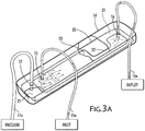
- FIG. 3a shows the etching chamber of FIGs. 1 and 2 alone (i.e. without the presence of a part having a part surface to be etched).
- Etching chamber 14 is shown having inlet port 15 connected to inlet line 15a, outlet port 16 connected to outlet line 16a and vacuum port 17 connected to vacuum line 17a.
- inlet line 15a is connected to a chemical etchant solution supply.
- outlet line 16a is connected to a chemical etchant solution return.
- vacuum line 17a is connected to a vacuum source.
- a controller may comprise a vacuum control to tailor and otherwise control the negative pressure applied by a vacuum to the etching chamber.
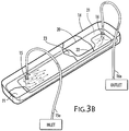
- Fig. 3b shows an exemplary etching chamber without the presence of a vacuum port. It is understood that this etching chamber would be used in conjunction with a mechanical means (not shown) to configure, position and retain the etching chamber proximate to a part surface, wherein a region of the part surface is to be chemically etched.
- a substantially continuous etchant solution flow is delivered to the etching chamber inlet (for example, from an etchant solution supply), and the etchant solution flow contacts the surface of the part to be etched before the flow of etchant solution leaves the chamber via the etching chamber outlet (flowing, for example to an etchant solution return.)
- the etchant solution is understood to be recirculated, but, if desired, the etchant solution may be filtered, and if necessary, replenished and reused.
- the etchant solution upon leaving the etching chamber, may be directed to material waste storage for eventual disposal.
- a further aspect comprises the step of establishing a flow rate of from about 3.79 liter (one gallon)/hour to about 3.79 liter (one gallon)/minute of etchant solution through the etching chamber, depending upon, for example, the total processing area on the part surface, the concentration or "strength" of the etchant solution, the depth of etching required on the part surface, etc.
- the etchant solution is understood to be recirculated, but, if desired, the etchant solution may be filtered, and if necessary, replenished and reused. Further, according to further aspects, it is understood that the etchant solution, upon leaving the etching chamber, may be directed to material waste storage for eventual disposal. As set forth above, the flow rate of the etchant solution through the etching chamber flows to at least partially fill the chamber at any predetermined rate that will accomplish the desired etching of the part surface being etched.
- a further aspect comprises the step of establishing a flow rate into the etching chamber of from about 3.79 liter (one gallon)/hour to about 3.79 liter (one gallon)/minute of etchant solution through the chamber, depending upon, for example, the total processing area on the part surface, the concentration or "strength" of the etchant solution, the depth of etching required on the part surface, etc.
- FIGs. 4 and 5 are flowcharts describing aspects of the present disclosure.
- FIG. 4 is a flowchart directed to one aspect showing a method for chemical etching of a part surface.
- an etching device having a chamber is positioned proximate to a part having a part surface 42.
- the etching device chamber engages with the part surface 44, with a flow of etchant solution then directed into the chamber to contact the part surface 46, and the flow then being directed out of the chamber after contacting the part surface 48.
- FIG. 5 shows a further method 50 for chemical etching of a part surface.
- an etching device having a chamber is positioned proximate to a part having a part surface 52.
- the etching device chamber engages with the part surface 54, generating a seal between the etching device and the part surface 55, with a flow of etchant solution then directed into the chamber to contact the part surface 56, and the flow then being directed out of the chamber after contacting the part surface 58.
- the step of the etching device engaging the part surface 54 and the step of generating a seal between the etching device and the part surface 55 may take place substantially simultaneously depending on the type of force being used to engage the etching device with the part surface.
- the seal is a substantially leak-proof seal.
- Operational verification includes inspection of O-rings, insuring that the vacuum system is operating properly and set to apply a sufficient negative pressure to seal the etching chamber in place on the part, verifying that the appropriate etchant solution supply is set to be dispensed at a desired and preselected flow rate from the etchant solution supply, and any and/or all other process controls show all "systems ready”.
- the chamber is located into position over a part to be etched.
- the chamber is then brought into intimate contact with the part surface such that the area to be etched is surrounded by the inner O-ring of the chamber.
- a vacuum is then applied (optionally along with other mechanical force applied) to insure a tight seal at the O-ring/part surface interface.
- a neutralizing solution may be supplied to the chemical etchant solution supply line as a rinsing step, followed by removing the neutralizing/rinsing solution from the chamber, and a drying step can be commenced by supplying an inert gas or air through the chamber to dry the part that has now been etched.
- a neutralizing solution can be provided from a neutralizing solution supply to the etching chamber via a separate neutralizing solution supply line. The vacuum and/or other mechanical forces used to maintain the chamber in place on the part surface are reversed and the etching chamber disengages from the part, (or the part is disengaged from the chamber), and the process may be repeated to chemically etch another part.
- a desired force may be applied to ensure a seal between the surface of a part to be etched and the chemical etching or milling chamber.
- Such forces include a mechanical force used in concert with a vacuum.
- the seals are understood to be made from any pliable material able to facilitate a substantially leak-proof seal and that is able to resist damage from exposure to typical etchant solutions.
- the etching chamber inlet line that delivers etchant solution from an etchant solution supply to the etching chamber, and the etching chamber outlet line that returns etchant solution from the etching chamber to an etchant solution return are also both understood to be constructed from a material that is able to resist damage from exposure to typical etchant solutions.
- Such suitable contemplated materials for seals, lines and portions of the chamber itself that would come into contact with an etchant solution include, for example and without limitation, polytetrafluoroethylene (PTFE) - (e.g. TeflonTM), poly(vinylchloride) (e.g. PVC Type I and II), polypropylene, high density polyethylene (HOPE), etc.
- PTFE polytetrafluoroethylene
- TeflonTM poly(vinylchloride)
- PVC Type I and II polypropylene
- HOPE high density polyethylene
- a vacuum may be employed to provide adequate force to press or compress the chamber against a part to be etched. In this way, adequate force other than a vacuum is contemplated to retain etchant solution in the chamber, the solution then contacting a part to be etched.
- vacuum levels would typically be measured in 2.54 cm (inches) of mercury or 2.54 cm (inches) of water or in terms of absolute pressure. Standard atmospheric pressure is understood as being approximately 0.10 N/mm 2 (15 pounds per square inch). If the absolute pressure under vacuum is set to about 0.03 N/mm 2 (5 pounds per square inch), then the actual delta pressure is about 0.07 N/mm 2 (10 pounds per square inch), which is easily attainable, and as would be readily understood.
- applying a vacuum or otherwise providing low pressure in the region between the two O-rings creates an "inward" force pushing the chamber against the part surface.
- This force is equal to the surface area of the vacuum region multiplied by the delta pressure between the external (ambient) atmosphere and the absolute pressure in the vacuum region. If the vacuum force exceeds the processing fluid pressure, then the chamber will remain in contact with the part. If not, then additional mechanical force will be required to maintain the chamber in contact with the part surface so that a substantially leak-proof seal is maintained. It is understood that more than one vacuum port may be present in the chamber.
- the methods and apparatuses of the present disclosure may be operated manually, or may be automated, and may be operated in concert with inspection and system control features.
- the system is automated, it is understood that the methods and apparatuses may be controlled on-site or remotely, and may be computer assisted, and supported by whatever computed programs would be required to run any desired automated chemical etching system.
- the methods and apparatuses disclosed herein can further be useful not only in conducting the highly targeted chemical etching of a part surface, but the apparatuses can assist in the actual part selection from a part supply, as well as part orientation.
- a sealing mechanism such as, for example a vacuum or other mechanical force to generate a seal between a part surface and the apparatus
- such sealing capacity can be useful in automated processes where the device can be brought into contact with, for example, a stack of parts to be chemically etched, and selectively remove each part for processing; or, if desired, chemically etch a part while located on a stack of parts, chemically etch the part, and then remove the part (after chemically etching a part surface) to a subsequent location along a process line.
- the apparatuses disclosed herein may require attachment to actuator arms, for example, or other devices able to move the etching chamber part of the disclosed apparatuses to desired locations.
Landscapes
- Chemical & Material Sciences (AREA)
- Engineering & Computer Science (AREA)
- Materials Engineering (AREA)
- Organic Chemistry (AREA)
- Chemical Kinetics & Catalysis (AREA)
- General Chemical & Material Sciences (AREA)
- Mechanical Engineering (AREA)
- Metallurgy (AREA)
- ing And Chemical Polishing (AREA)
- Weting (AREA)
Claims (11)
- Procédé de gravure chimique d'une surface d'une pièce, le procédé comportant étapes consistant à :positionner un dispositif de gravure à proximité d'une pièce (12), ladite pièce possédant une surface de pièce, ledit dispositif de gravure comprenant :une chambre (14) ;un pourtour de chambre ;au moins une entrée (15) de chambre ;au moins une sortie (16) de chambre ; etau moins un orifice à vide (17) en communication avec une source de vide (17b) ;mettre en contact le dispositif de gravure avec la surface de pièce ; etdiriger un flux de solution d'agent de gravure vers l'entrée de chambre, de sorte que la solution d'agent de gravure entre en contact avec la surface de pièce pendant une quantité prédéfinie de temps avant de sortir par la sortie de chambre, caractérisé en ce quele pourtour de chambre comprend deux joints toriques espacés, l'au moins un orifice à vide (17) étant positionné sur le dispositif de gravure entre les deux joints toriques espacés, la source de vide (17b) générant un vide entre les deux joints toriques espacés.
- Procédé selon la revendication 1, dans lequel le pourtour de chambre entoure au moins une région de la surface de pièce exposée pour gravure chimique.
- Procédé selon la revendication 1 ou 2, dans lequel le dispositif de gravure comprend en outre au moins un mécanisme d'étanchéité sur le dispositif, ledit mécanisme d'étanchéité entrant en contact avec la surface de pièce.
- Procédé selon l'une quelconque des revendications 1 à 3, dans lequel un moyen mécanique maintient la chambre de dispositif de gravure en contact avec la surface de pièce avec une force suffisante pour maintenir un joint sensiblement étanche aux fuites au niveau d'une interface pourtour de chambre/surface de pièce, de préférence le moyen mécanique générant une force allant d'environ 1,75 à environ 17,51 N/mm (10 à 100 livres par pouce linéaire) au niveau de l'interface chambre/surface de pièce.
- Procédé selon l'une quelconque des revendications précédentes, dans lequel le flux de solution d'agent de gravure va de 3,79 litres par heure à 3,79 litres par minutes (un gallon par heure à un gallon par minute).
- Appareil de gravure chimique d'une surface d'une pièce, ledit appareil comportant :une chambre de gravure (14) ;un pourtour de chambre de gravure ;au moins une entrée (15) de chambre de gravure ;au moins une sortie (16) de chambre de gravure ; etau moins un orifice à vide (17), ledit orifice à vide étant en communication avec une source de vide (17b),dans lequel la chambre de gravure est conçue pour permettre un flux de solution d'agent de gravure à travers la chambre de gravure,le pourtour de chambre comprend deux joints toriques espacés, l'au moins un orifice à vide (17) étant positionné sur le dispositif de gravure entre les deux joints toriques espacés, la source de vide (17b) générant un vide entre les deux joints toriques espacés.
- Appareil selon la revendication 6, dans lequel le flux d'une solution de gravure est conçu pour s'écouler vers l'entrée (15) de chambre de gravure, de sorte que la solution d'agent de gravure entre en contact avec la surface de pièce pendant une quantité prédéfinie de temps avant de sortir par la sortie (16) de chambre de gravure.
- Appareil selon la revendication 6 ou 7, dans lequel la sortie de chambre de gravure est en communication avec un retour (16b) de solution d'agent de gravure.
- Appareil selon l'une quelconque des revendications 6 à 8, dans lequel l'entrée (15) de la chambre de gravure est en communication avec une alimentation (15b) en solution d'agent de gravure.
- Appareil selon l'une quelconque des revendications 6 à 9, dans lequel le pourtour de chambre de gravure comprend en outre un joint.
- Appareil selon l'une quelconque des revendications 6 à 10, comprenant en outre un moyen mécanique pour maintenir la chambre de gravure en contact avec la surface de pièce avec une force suffisante pour maintenir un joint sensiblement étanche aux fuites au niveau d'une interface pourtour de chambre de gravure/surface de pièce.
Applications Claiming Priority (1)
| Application Number | Priority Date | Filing Date | Title |
|---|---|---|---|
| US14/712,208 US9624430B2 (en) | 2015-05-14 | 2015-05-14 | Methods and apparatuses for selective chemical etching |
Publications (2)
| Publication Number | Publication Date |
|---|---|
| EP3093373A1 EP3093373A1 (fr) | 2016-11-16 |
| EP3093373B1 true EP3093373B1 (fr) | 2019-07-31 |
Family
ID=55699309
Family Applications (1)
| Application Number | Title | Priority Date | Filing Date |
|---|---|---|---|
| EP16156689.8A Active EP3093373B1 (fr) | 2015-05-14 | 2016-02-22 | Procédés et appareils de gravure chimique sélective |
Country Status (2)
| Country | Link |
|---|---|
| US (2) | US9624430B2 (fr) |
| EP (1) | EP3093373B1 (fr) |
Families Citing this family (3)
| Publication number | Priority date | Publication date | Assignee | Title |
|---|---|---|---|---|
| US9624430B2 (en) * | 2015-05-14 | 2017-04-18 | The Boeing Company | Methods and apparatuses for selective chemical etching |
| US20220117092A1 (en) * | 2018-08-16 | 2022-04-14 | Shah Jainil | Continuous etching system |
| US10654103B2 (en) | 2018-09-20 | 2020-05-19 | General Electric Company | Method of manufacturing a fin structure for heat exchanger |
Family Cites Families (16)
| Publication number | Priority date | Publication date | Assignee | Title |
|---|---|---|---|---|
| US5096536A (en) * | 1990-06-12 | 1992-03-17 | Micron Technology, Inc. | Method and apparatus useful in the plasma etching of semiconductor materials |
| JPH04301088A (ja) | 1991-03-29 | 1992-10-23 | Aisin Seiki Co Ltd | エッチング処理方法 |
| US5271798A (en) | 1993-03-29 | 1993-12-21 | Micron Technology, Inc. | Method for selective removal of a material from a wafer's alignment marks |
| US6494219B1 (en) * | 2000-03-22 | 2002-12-17 | Applied Materials, Inc. | Apparatus with etchant mixing assembly for removal of unwanted electroplating deposits |
| AU2001290171A1 (en) * | 2000-07-26 | 2002-02-05 | Tokyo Electron Limited | High pressure processing chamber for semiconductor substrate |
| US20050247673A1 (en) * | 2004-05-07 | 2005-11-10 | International Business Machines Corporation | Confinement of fluids on surfaces |
| US20070256710A1 (en) * | 2004-06-10 | 2007-11-08 | Dtl Technologies, Inc. | Chemical process operations on wafers having through-holes and a pressure differential between the major surfaces thereof |
| US20060065622A1 (en) * | 2004-09-27 | 2006-03-30 | Floyd Philip D | Method and system for xenon fluoride etching with enhanced efficiency |
| GB2438385B (en) | 2006-05-23 | 2008-09-17 | Rolls Royce Plc | Surface treatment device |
| US20080149594A1 (en) * | 2006-06-16 | 2008-06-26 | Packer Engineering, Inc. | Apparatus and process for forming and handling porous materials |
| US8822346B1 (en) * | 2008-06-10 | 2014-09-02 | Intermolecular, Inc. | Method and apparatus for self-aligned layer removal |
| US9455139B2 (en) * | 2009-06-17 | 2016-09-27 | Novellus Systems, Inc. | Methods and apparatus for wetting pretreatment for through resist metal plating |
| CN102859663B (zh) * | 2010-04-26 | 2015-06-10 | 三菱电机株式会社 | 湿式蚀刻用夹具 |
| GB2489665A (en) | 2011-03-24 | 2012-10-10 | Rolls Royce Plc | Application of treatment fluids to components |
| JP2015216255A (ja) * | 2014-05-12 | 2015-12-03 | キヤノン株式会社 | エッチングチャンバー、および基板の製造方法 |
| US9624430B2 (en) * | 2015-05-14 | 2017-04-18 | The Boeing Company | Methods and apparatuses for selective chemical etching |
-
2015
- 2015-05-14 US US14/712,208 patent/US9624430B2/en not_active Expired - Fee Related
-
2016
- 2016-02-22 EP EP16156689.8A patent/EP3093373B1/fr active Active
-
2017
- 2017-03-03 US US15/448,794 patent/US10533134B2/en active Active
Non-Patent Citations (1)
| Title |
|---|
| None * |
Also Published As
| Publication number | Publication date |
|---|---|
| US10533134B2 (en) | 2020-01-14 |
| US20160333269A1 (en) | 2016-11-17 |
| US9624430B2 (en) | 2017-04-18 |
| EP3093373A1 (fr) | 2016-11-16 |
| US20170174987A1 (en) | 2017-06-22 |
Similar Documents
| Publication | Publication Date | Title |
|---|---|---|
| TWI533946B (zh) | 噴頭清潔的方法與設備 | |
| US10533134B2 (en) | Methods and apparatuses for selective chemical etching | |
| US5045117A (en) | System for removing flux residues from printed wiring assemblies | |
| TWI313480B (en) | High-pressure processing chamber for a semiconductor wafer | |
| CN110036346B (zh) | 曝光后处理设备 | |
| JP2018511935A5 (fr) | ||
| EP3417090B1 (fr) | Traitement chimique de pièces fabriquées par un procédé de fabrication additive | |
| US8298344B2 (en) | Method of processing workpieces using a vessel with a low pressure space surrounding a processing space for the purpose of preventing the leakage of atmosphere into the processing space | |
| CN103016793B (zh) | 用于气动阀连续运行的电磁阀旁路系统 | |
| KR101981899B1 (ko) | 클리닝 기능이 구비된 반도체 공정 장비 및 이를 이용한 반도체 공정 장비의 클리닝 방법 | |
| KR20170098162A (ko) | 기판 처리 장치 및 기판 처리 방법 | |
| TWI638383B (zh) | 處理工件表面的方法 | |
| US9396912B2 (en) | Methods for mixed acid cleaning of showerhead electrodes | |
| US20130056036A1 (en) | Integrated processing and critical point drying systems for semiconductor and mems devices | |
| KR20010098745A (ko) | 기판 처리방법 및 기판 처리장치 | |
| JP2007123393A (ja) | 基板処理装置 | |
| US5913721A (en) | Ventilation hood with enhanced particle control and method of using | |
| CN111326444B (zh) | 半导体蚀刻设备 | |
| KR20070093696A (ko) | 반도체 제조설비의 진공 시스템 | |
| CN107610998B (zh) | 一种能够调节内外压差的气相腐蚀腔体及利用其进行气相腐蚀的方法 | |
| KR20140008266A (ko) | 냉각 유체의 유독성 가스 누설 차단장치를 구비한 반도체 공정 설비용 칠러 | |
| US20250323065A1 (en) | Apparatus for semiconductor solvent processing utilized for 3d and traditional process flows | |
| TWI914967B (zh) | 基板處理裝置 | |
| KR20210052766A (ko) | 기판 처리 장치 | |
| KR101009965B1 (ko) | 배기 조절 장치 |
Legal Events
| Date | Code | Title | Description |
|---|---|---|---|
| PUAI | Public reference made under article 153(3) epc to a published international application that has entered the european phase |
Free format text: ORIGINAL CODE: 0009012 |
|
| 17P | Request for examination filed |
Effective date: 20160222 |
|
| AK | Designated contracting states |
Kind code of ref document: A1 Designated state(s): AL AT BE BG CH CY CZ DE DK EE ES FI FR GB GR HR HU IE IS IT LI LT LU LV MC MK MT NL NO PL PT RO RS SE SI SK SM TR |
|
| AX | Request for extension of the european patent |
Extension state: BA ME |
|
| RBV | Designated contracting states (corrected) |
Designated state(s): AL AT BE BG CH CY CZ DE DK EE ES FI FR GB GR HR HU IE IS IT LI LT LU LV MC MK MT NL NO PL PT RO RS SE SI SK SM TR |
|
| GRAP | Despatch of communication of intention to grant a patent |
Free format text: ORIGINAL CODE: EPIDOSNIGR1 |
|
| STAA | Information on the status of an ep patent application or granted ep patent |
Free format text: STATUS: GRANT OF PATENT IS INTENDED |
|
| INTG | Intention to grant announced |
Effective date: 20180802 |
|
| GRAJ | Information related to disapproval of communication of intention to grant by the applicant or resumption of examination proceedings by the epo deleted |
Free format text: ORIGINAL CODE: EPIDOSDIGR1 |
|
| STAA | Information on the status of an ep patent application or granted ep patent |
Free format text: STATUS: REQUEST FOR EXAMINATION WAS MADE |
|
| INTC | Intention to grant announced (deleted) | ||
| GRAP | Despatch of communication of intention to grant a patent |
Free format text: ORIGINAL CODE: EPIDOSNIGR1 |
|
| STAA | Information on the status of an ep patent application or granted ep patent |
Free format text: STATUS: GRANT OF PATENT IS INTENDED |
|
| INTG | Intention to grant announced |
Effective date: 20190123 |
|
| GRAS | Grant fee paid |
Free format text: ORIGINAL CODE: EPIDOSNIGR3 |
|
| GRAA | (expected) grant |
Free format text: ORIGINAL CODE: 0009210 |
|
| STAA | Information on the status of an ep patent application or granted ep patent |
Free format text: STATUS: THE PATENT HAS BEEN GRANTED |
|
| AK | Designated contracting states |
Kind code of ref document: B1 Designated state(s): AL AT BE BG CH CY CZ DE DK EE ES FI FR GB GR HR HU IE IS IT LI LT LU LV MC MK MT NL NO PL PT RO RS SE SI SK SM TR |
|
| REG | Reference to a national code |
Ref country code: CH Ref legal event code: EP Ref country code: GB Ref legal event code: FG4D |
|
| REG | Reference to a national code |
Ref country code: AT Ref legal event code: REF Ref document number: 1160976 Country of ref document: AT Kind code of ref document: T Effective date: 20190815 |
|
| REG | Reference to a national code |
Ref country code: IE Ref legal event code: FG4D |
|
| REG | Reference to a national code |
Ref country code: DE Ref legal event code: R096 Ref document number: 602016017565 Country of ref document: DE |
|
| REG | Reference to a national code |
Ref country code: NL Ref legal event code: MP Effective date: 20190731 |
|
| REG | Reference to a national code |
Ref country code: LT Ref legal event code: MG4D |
|
| REG | Reference to a national code |
Ref country code: AT Ref legal event code: MK05 Ref document number: 1160976 Country of ref document: AT Kind code of ref document: T Effective date: 20190731 |
|
| PG25 | Lapsed in a contracting state [announced via postgrant information from national office to epo] |
Ref country code: PT Free format text: LAPSE BECAUSE OF FAILURE TO SUBMIT A TRANSLATION OF THE DESCRIPTION OR TO PAY THE FEE WITHIN THE PRESCRIBED TIME-LIMIT Effective date: 20191202 Ref country code: AT Free format text: LAPSE BECAUSE OF FAILURE TO SUBMIT A TRANSLATION OF THE DESCRIPTION OR TO PAY THE FEE WITHIN THE PRESCRIBED TIME-LIMIT Effective date: 20190731 Ref country code: SE Free format text: LAPSE BECAUSE OF FAILURE TO SUBMIT A TRANSLATION OF THE DESCRIPTION OR TO PAY THE FEE WITHIN THE PRESCRIBED TIME-LIMIT Effective date: 20190731 Ref country code: NO Free format text: LAPSE BECAUSE OF FAILURE TO SUBMIT A TRANSLATION OF THE DESCRIPTION OR TO PAY THE FEE WITHIN THE PRESCRIBED TIME-LIMIT Effective date: 20191031 Ref country code: FI Free format text: LAPSE BECAUSE OF FAILURE TO SUBMIT A TRANSLATION OF THE DESCRIPTION OR TO PAY THE FEE WITHIN THE PRESCRIBED TIME-LIMIT Effective date: 20190731 Ref country code: HR Free format text: LAPSE BECAUSE OF FAILURE TO SUBMIT A TRANSLATION OF THE DESCRIPTION OR TO PAY THE FEE WITHIN THE PRESCRIBED TIME-LIMIT Effective date: 20190731 Ref country code: NL Free format text: LAPSE BECAUSE OF FAILURE TO SUBMIT A TRANSLATION OF THE DESCRIPTION OR TO PAY THE FEE WITHIN THE PRESCRIBED TIME-LIMIT Effective date: 20190731 Ref country code: BG Free format text: LAPSE BECAUSE OF FAILURE TO SUBMIT A TRANSLATION OF THE DESCRIPTION OR TO PAY THE FEE WITHIN THE PRESCRIBED TIME-LIMIT Effective date: 20191031 Ref country code: LT Free format text: LAPSE BECAUSE OF FAILURE TO SUBMIT A TRANSLATION OF THE DESCRIPTION OR TO PAY THE FEE WITHIN THE PRESCRIBED TIME-LIMIT Effective date: 20190731 |
|
| PG25 | Lapsed in a contracting state [announced via postgrant information from national office to epo] |
Ref country code: GR Free format text: LAPSE BECAUSE OF FAILURE TO SUBMIT A TRANSLATION OF THE DESCRIPTION OR TO PAY THE FEE WITHIN THE PRESCRIBED TIME-LIMIT Effective date: 20191101 Ref country code: AL Free format text: LAPSE BECAUSE OF FAILURE TO SUBMIT A TRANSLATION OF THE DESCRIPTION OR TO PAY THE FEE WITHIN THE PRESCRIBED TIME-LIMIT Effective date: 20190731 Ref country code: ES Free format text: LAPSE BECAUSE OF FAILURE TO SUBMIT A TRANSLATION OF THE DESCRIPTION OR TO PAY THE FEE WITHIN THE PRESCRIBED TIME-LIMIT Effective date: 20190731 Ref country code: IS Free format text: LAPSE BECAUSE OF FAILURE TO SUBMIT A TRANSLATION OF THE DESCRIPTION OR TO PAY THE FEE WITHIN THE PRESCRIBED TIME-LIMIT Effective date: 20191130 Ref country code: LV Free format text: LAPSE BECAUSE OF FAILURE TO SUBMIT A TRANSLATION OF THE DESCRIPTION OR TO PAY THE FEE WITHIN THE PRESCRIBED TIME-LIMIT Effective date: 20190731 Ref country code: RS Free format text: LAPSE BECAUSE OF FAILURE TO SUBMIT A TRANSLATION OF THE DESCRIPTION OR TO PAY THE FEE WITHIN THE PRESCRIBED TIME-LIMIT Effective date: 20190731 |
|
| PG25 | Lapsed in a contracting state [announced via postgrant information from national office to epo] |
Ref country code: TR Free format text: LAPSE BECAUSE OF FAILURE TO SUBMIT A TRANSLATION OF THE DESCRIPTION OR TO PAY THE FEE WITHIN THE PRESCRIBED TIME-LIMIT Effective date: 20190731 |
|
| PG25 | Lapsed in a contracting state [announced via postgrant information from national office to epo] |
Ref country code: RO Free format text: LAPSE BECAUSE OF FAILURE TO SUBMIT A TRANSLATION OF THE DESCRIPTION OR TO PAY THE FEE WITHIN THE PRESCRIBED TIME-LIMIT Effective date: 20190731 Ref country code: PL Free format text: LAPSE BECAUSE OF FAILURE TO SUBMIT A TRANSLATION OF THE DESCRIPTION OR TO PAY THE FEE WITHIN THE PRESCRIBED TIME-LIMIT Effective date: 20190731 Ref country code: DK Free format text: LAPSE BECAUSE OF FAILURE TO SUBMIT A TRANSLATION OF THE DESCRIPTION OR TO PAY THE FEE WITHIN THE PRESCRIBED TIME-LIMIT Effective date: 20190731 Ref country code: IT Free format text: LAPSE BECAUSE OF FAILURE TO SUBMIT A TRANSLATION OF THE DESCRIPTION OR TO PAY THE FEE WITHIN THE PRESCRIBED TIME-LIMIT Effective date: 20190731 Ref country code: EE Free format text: LAPSE BECAUSE OF FAILURE TO SUBMIT A TRANSLATION OF THE DESCRIPTION OR TO PAY THE FEE WITHIN THE PRESCRIBED TIME-LIMIT Effective date: 20190731 |
|
| PG25 | Lapsed in a contracting state [announced via postgrant information from national office to epo] |
Ref country code: IS Free format text: LAPSE BECAUSE OF FAILURE TO SUBMIT A TRANSLATION OF THE DESCRIPTION OR TO PAY THE FEE WITHIN THE PRESCRIBED TIME-LIMIT Effective date: 20200224 Ref country code: CZ Free format text: LAPSE BECAUSE OF FAILURE TO SUBMIT A TRANSLATION OF THE DESCRIPTION OR TO PAY THE FEE WITHIN THE PRESCRIBED TIME-LIMIT Effective date: 20190731 Ref country code: SM Free format text: LAPSE BECAUSE OF FAILURE TO SUBMIT A TRANSLATION OF THE DESCRIPTION OR TO PAY THE FEE WITHIN THE PRESCRIBED TIME-LIMIT Effective date: 20190731 Ref country code: SK Free format text: LAPSE BECAUSE OF FAILURE TO SUBMIT A TRANSLATION OF THE DESCRIPTION OR TO PAY THE FEE WITHIN THE PRESCRIBED TIME-LIMIT Effective date: 20190731 |
|
| REG | Reference to a national code |
Ref country code: DE Ref legal event code: R097 Ref document number: 602016017565 Country of ref document: DE |
|
| PLBE | No opposition filed within time limit |
Free format text: ORIGINAL CODE: 0009261 |
|
| STAA | Information on the status of an ep patent application or granted ep patent |
Free format text: STATUS: NO OPPOSITION FILED WITHIN TIME LIMIT |
|
| PG2D | Information on lapse in contracting state deleted |
Ref country code: IS |
|
| PG25 | Lapsed in a contracting state [announced via postgrant information from national office to epo] |
Ref country code: IS Free format text: LAPSE BECAUSE OF FAILURE TO SUBMIT A TRANSLATION OF THE DESCRIPTION OR TO PAY THE FEE WITHIN THE PRESCRIBED TIME-LIMIT Effective date: 20191030 |
|
| 26N | No opposition filed |
Effective date: 20200603 |
|
| PG25 | Lapsed in a contracting state [announced via postgrant information from national office to epo] |
Ref country code: SI Free format text: LAPSE BECAUSE OF FAILURE TO SUBMIT A TRANSLATION OF THE DESCRIPTION OR TO PAY THE FEE WITHIN THE PRESCRIBED TIME-LIMIT Effective date: 20190731 |
|
| REG | Reference to a national code |
Ref country code: CH Ref legal event code: PL |
|
| REG | Reference to a national code |
Ref country code: BE Ref legal event code: MM Effective date: 20200229 |
|
| PG25 | Lapsed in a contracting state [announced via postgrant information from national office to epo] |
Ref country code: MC Free format text: LAPSE BECAUSE OF FAILURE TO SUBMIT A TRANSLATION OF THE DESCRIPTION OR TO PAY THE FEE WITHIN THE PRESCRIBED TIME-LIMIT Effective date: 20190731 Ref country code: LU Free format text: LAPSE BECAUSE OF NON-PAYMENT OF DUE FEES Effective date: 20200222 |
|
| PG25 | Lapsed in a contracting state [announced via postgrant information from national office to epo] |
Ref country code: LI Free format text: LAPSE BECAUSE OF NON-PAYMENT OF DUE FEES Effective date: 20200229 Ref country code: CH Free format text: LAPSE BECAUSE OF NON-PAYMENT OF DUE FEES Effective date: 20200229 |
|
| PG25 | Lapsed in a contracting state [announced via postgrant information from national office to epo] |
Ref country code: IE Free format text: LAPSE BECAUSE OF NON-PAYMENT OF DUE FEES Effective date: 20200222 |
|
| PG25 | Lapsed in a contracting state [announced via postgrant information from national office to epo] |
Ref country code: BE Free format text: LAPSE BECAUSE OF NON-PAYMENT OF DUE FEES Effective date: 20200229 |
|
| PG25 | Lapsed in a contracting state [announced via postgrant information from national office to epo] |
Ref country code: MT Free format text: LAPSE BECAUSE OF FAILURE TO SUBMIT A TRANSLATION OF THE DESCRIPTION OR TO PAY THE FEE WITHIN THE PRESCRIBED TIME-LIMIT Effective date: 20190731 Ref country code: CY Free format text: LAPSE BECAUSE OF FAILURE TO SUBMIT A TRANSLATION OF THE DESCRIPTION OR TO PAY THE FEE WITHIN THE PRESCRIBED TIME-LIMIT Effective date: 20190731 |
|
| PG25 | Lapsed in a contracting state [announced via postgrant information from national office to epo] |
Ref country code: MK Free format text: LAPSE BECAUSE OF FAILURE TO SUBMIT A TRANSLATION OF THE DESCRIPTION OR TO PAY THE FEE WITHIN THE PRESCRIBED TIME-LIMIT Effective date: 20190731 |
|
| P01 | Opt-out of the competence of the unified patent court (upc) registered |
Effective date: 20230516 |
|
| PGFP | Annual fee paid to national office [announced via postgrant information from national office to epo] |
Ref country code: DE Payment date: 20240228 Year of fee payment: 9 Ref country code: GB Payment date: 20240227 Year of fee payment: 9 |
|
| PGFP | Annual fee paid to national office [announced via postgrant information from national office to epo] |
Ref country code: FR Payment date: 20240226 Year of fee payment: 9 |
|
| REG | Reference to a national code |
Ref country code: DE Ref legal event code: R119 Ref document number: 602016017565 Country of ref document: DE |
|
| GBPC | Gb: european patent ceased through non-payment of renewal fee |
Effective date: 20250222 |
|
| PG25 | Lapsed in a contracting state [announced via postgrant information from national office to epo] |
Ref country code: DE Free format text: LAPSE BECAUSE OF NON-PAYMENT OF DUE FEES Effective date: 20250902 |
|
| PG25 | Lapsed in a contracting state [announced via postgrant information from national office to epo] |
Ref country code: GB Free format text: LAPSE BECAUSE OF NON-PAYMENT OF DUE FEES Effective date: 20250222 |
|
| PG25 | Lapsed in a contracting state [announced via postgrant information from national office to epo] |
Ref country code: FR Free format text: LAPSE BECAUSE OF NON-PAYMENT OF DUE FEES Effective date: 20250228 |