EP3093401B1 - Appareil pour commander une opération combinée d'un engin de chantier - Google Patents
Appareil pour commander une opération combinée d'un engin de chantier Download PDFInfo
- Publication number
- EP3093401B1 EP3093401B1 EP14873984.0A EP14873984A EP3093401B1 EP 3093401 B1 EP3093401 B1 EP 3093401B1 EP 14873984 A EP14873984 A EP 14873984A EP 3093401 B1 EP3093401 B1 EP 3093401B1
- Authority
- EP
- European Patent Office
- Prior art keywords
- driving
- pump
- valve
- swing
- construction machine
- Prior art date
- Legal status (The legal status is an assumption and is not a legal conclusion. Google has not performed a legal analysis and makes no representation as to the accuracy of the status listed.)
- Active
Links
Images


Classifications
-
- E—FIXED CONSTRUCTIONS
- E02—HYDRAULIC ENGINEERING; FOUNDATIONS; SOIL SHIFTING
- E02F—DREDGING; SOIL-SHIFTING
- E02F9/00—Component parts of dredgers or soil-shifting machines, not restricted to one of the kinds covered by groups E02F3/00 - E02F7/00
- E02F9/20—Drives; Control devices
- E02F9/22—Hydraulic or pneumatic drives
-
- F—MECHANICAL ENGINEERING; LIGHTING; HEATING; WEAPONS; BLASTING
- F15—FLUID-PRESSURE ACTUATORS; HYDRAULICS OR PNEUMATICS IN GENERAL
- F15B—SYSTEMS ACTING BY MEANS OF FLUIDS IN GENERAL; FLUID-PRESSURE ACTUATORS, e.g. SERVOMOTORS; DETAILS OF FLUID-PRESSURE SYSTEMS, NOT OTHERWISE PROVIDED FOR
- F15B11/00—Servomotor systems without provision for follow-up action; Circuits therefor
- F15B11/16—Servomotor systems without provision for follow-up action; Circuits therefor with two or more servomotors
- F15B11/17—Servomotor systems without provision for follow-up action; Circuits therefor with two or more servomotors using two or more pumps
-
- E—FIXED CONSTRUCTIONS
- E02—HYDRAULIC ENGINEERING; FOUNDATIONS; SOIL SHIFTING
- E02F—DREDGING; SOIL-SHIFTING
- E02F9/00—Component parts of dredgers or soil-shifting machines, not restricted to one of the kinds covered by groups E02F3/00 - E02F7/00
- E02F9/20—Drives; Control devices
- E02F9/22—Hydraulic or pneumatic drives
- E02F9/2221—Control of flow rate; Load sensing arrangements
- E02F9/2239—Control of flow rate; Load sensing arrangements using two or more pumps with cross-assistance
-
- E—FIXED CONSTRUCTIONS
- E02—HYDRAULIC ENGINEERING; FOUNDATIONS; SOIL SHIFTING
- E02F—DREDGING; SOIL-SHIFTING
- E02F9/00—Component parts of dredgers or soil-shifting machines, not restricted to one of the kinds covered by groups E02F3/00 - E02F7/00
- E02F9/20—Drives; Control devices
- E02F9/22—Hydraulic or pneumatic drives
- E02F9/2278—Hydraulic circuits
- E02F9/2282—Systems using center bypass type changeover valves
-
- E—FIXED CONSTRUCTIONS
- E02—HYDRAULIC ENGINEERING; FOUNDATIONS; SOIL SHIFTING
- E02F—DREDGING; SOIL-SHIFTING
- E02F9/00—Component parts of dredgers or soil-shifting machines, not restricted to one of the kinds covered by groups E02F3/00 - E02F7/00
- E02F9/20—Drives; Control devices
- E02F9/22—Hydraulic or pneumatic drives
- E02F9/2278—Hydraulic circuits
- E02F9/2285—Pilot-operated systems
-
- F—MECHANICAL ENGINEERING; LIGHTING; HEATING; WEAPONS; BLASTING
- F15—FLUID-PRESSURE ACTUATORS; HYDRAULICS OR PNEUMATICS IN GENERAL
- F15B—SYSTEMS ACTING BY MEANS OF FLUIDS IN GENERAL; FLUID-PRESSURE ACTUATORS, e.g. SERVOMOTORS; DETAILS OF FLUID-PRESSURE SYSTEMS, NOT OTHERWISE PROVIDED FOR
- F15B11/00—Servomotor systems without provision for follow-up action; Circuits therefor
- F15B11/16—Servomotor systems without provision for follow-up action; Circuits therefor with two or more servomotors
- F15B11/20—Servomotor systems without provision for follow-up action; Circuits therefor with two or more servomotors controlling several interacting or sequentially-operating members
-
- F—MECHANICAL ENGINEERING; LIGHTING; HEATING; WEAPONS; BLASTING
- F15—FLUID-PRESSURE ACTUATORS; HYDRAULICS OR PNEUMATICS IN GENERAL
- F15B—SYSTEMS ACTING BY MEANS OF FLUIDS IN GENERAL; FLUID-PRESSURE ACTUATORS, e.g. SERVOMOTORS; DETAILS OF FLUID-PRESSURE SYSTEMS, NOT OTHERWISE PROVIDED FOR
- F15B13/00—Details of servomotor systems ; Valves for servomotor systems
- F15B13/02—Fluid distribution or supply devices characterised by their adaptation to the control of servomotors
-
- F—MECHANICAL ENGINEERING; LIGHTING; HEATING; WEAPONS; BLASTING
- F15—FLUID-PRESSURE ACTUATORS; HYDRAULICS OR PNEUMATICS IN GENERAL
- F15B—SYSTEMS ACTING BY MEANS OF FLUIDS IN GENERAL; FLUID-PRESSURE ACTUATORS, e.g. SERVOMOTORS; DETAILS OF FLUID-PRESSURE SYSTEMS, NOT OTHERWISE PROVIDED FOR
- F15B2211/00—Circuits for servomotor systems
- F15B2211/20—Fluid pressure source, e.g. accumulator or variable axial piston pump
- F15B2211/205—Systems with pumps
- F15B2211/20576—Systems with pumps with multiple pumps
-
- F—MECHANICAL ENGINEERING; LIGHTING; HEATING; WEAPONS; BLASTING
- F15—FLUID-PRESSURE ACTUATORS; HYDRAULICS OR PNEUMATICS IN GENERAL
- F15B—SYSTEMS ACTING BY MEANS OF FLUIDS IN GENERAL; FLUID-PRESSURE ACTUATORS, e.g. SERVOMOTORS; DETAILS OF FLUID-PRESSURE SYSTEMS, NOT OTHERWISE PROVIDED FOR
- F15B2211/00—Circuits for servomotor systems
- F15B2211/30—Directional control
- F15B2211/305—Directional control characterised by the type of valves
- F15B2211/3056—Assemblies of multiple valves
- F15B2211/3059—Assemblies of multiple valves having multiple valves for multiple output members
- F15B2211/30595—Assemblies of multiple valves having multiple valves for multiple output members with additional valves between the groups of valves for multiple output members
-
- F—MECHANICAL ENGINEERING; LIGHTING; HEATING; WEAPONS; BLASTING
- F15—FLUID-PRESSURE ACTUATORS; HYDRAULICS OR PNEUMATICS IN GENERAL
- F15B—SYSTEMS ACTING BY MEANS OF FLUIDS IN GENERAL; FLUID-PRESSURE ACTUATORS, e.g. SERVOMOTORS; DETAILS OF FLUID-PRESSURE SYSTEMS, NOT OTHERWISE PROVIDED FOR
- F15B2211/00—Circuits for servomotor systems
- F15B2211/30—Directional control
- F15B2211/31—Directional control characterised by the positions of the valve element
- F15B2211/3105—Neutral or centre positions
- F15B2211/3116—Neutral or centre positions the pump port being open in the centre position, e.g. so-called open centre
-
- F—MECHANICAL ENGINEERING; LIGHTING; HEATING; WEAPONS; BLASTING
- F15—FLUID-PRESSURE ACTUATORS; HYDRAULICS OR PNEUMATICS IN GENERAL
- F15B—SYSTEMS ACTING BY MEANS OF FLUIDS IN GENERAL; FLUID-PRESSURE ACTUATORS, e.g. SERVOMOTORS; DETAILS OF FLUID-PRESSURE SYSTEMS, NOT OTHERWISE PROVIDED FOR
- F15B2211/00—Circuits for servomotor systems
- F15B2211/40—Flow control
- F15B2211/415—Flow control characterised by the connections of the flow control means in the circuit
- F15B2211/41554—Flow control characterised by the connections of the flow control means in the circuit being connected to a return line and a directional control valve
-
- F—MECHANICAL ENGINEERING; LIGHTING; HEATING; WEAPONS; BLASTING
- F15—FLUID-PRESSURE ACTUATORS; HYDRAULICS OR PNEUMATICS IN GENERAL
- F15B—SYSTEMS ACTING BY MEANS OF FLUIDS IN GENERAL; FLUID-PRESSURE ACTUATORS, e.g. SERVOMOTORS; DETAILS OF FLUID-PRESSURE SYSTEMS, NOT OTHERWISE PROVIDED FOR
- F15B2211/00—Circuits for servomotor systems
- F15B2211/40—Flow control
- F15B2211/42—Flow control characterised by the type of actuation
- F15B2211/428—Flow control characterised by the type of actuation actuated by fluid pressure
-
- F—MECHANICAL ENGINEERING; LIGHTING; HEATING; WEAPONS; BLASTING
- F15—FLUID-PRESSURE ACTUATORS; HYDRAULICS OR PNEUMATICS IN GENERAL
- F15B—SYSTEMS ACTING BY MEANS OF FLUIDS IN GENERAL; FLUID-PRESSURE ACTUATORS, e.g. SERVOMOTORS; DETAILS OF FLUID-PRESSURE SYSTEMS, NOT OTHERWISE PROVIDED FOR
- F15B2211/00—Circuits for servomotor systems
- F15B2211/40—Flow control
- F15B2211/45—Control of bleed-off flow, e.g. control of bypass flow to the return line
-
- F—MECHANICAL ENGINEERING; LIGHTING; HEATING; WEAPONS; BLASTING
- F15—FLUID-PRESSURE ACTUATORS; HYDRAULICS OR PNEUMATICS IN GENERAL
- F15B—SYSTEMS ACTING BY MEANS OF FLUIDS IN GENERAL; FLUID-PRESSURE ACTUATORS, e.g. SERVOMOTORS; DETAILS OF FLUID-PRESSURE SYSTEMS, NOT OTHERWISE PROVIDED FOR
- F15B2211/00—Circuits for servomotor systems
- F15B2211/60—Circuit components or control therefor
- F15B2211/635—Circuits providing pilot pressure to pilot pressure-controlled fluid circuit elements
- F15B2211/6355—Circuits providing pilot pressure to pilot pressure-controlled fluid circuit elements having valve means
-
- F—MECHANICAL ENGINEERING; LIGHTING; HEATING; WEAPONS; BLASTING
- F15—FLUID-PRESSURE ACTUATORS; HYDRAULICS OR PNEUMATICS IN GENERAL
- F15B—SYSTEMS ACTING BY MEANS OF FLUIDS IN GENERAL; FLUID-PRESSURE ACTUATORS, e.g. SERVOMOTORS; DETAILS OF FLUID-PRESSURE SYSTEMS, NOT OTHERWISE PROVIDED FOR
- F15B2211/00—Circuits for servomotor systems
- F15B2211/70—Output members, e.g. hydraulic motors or cylinders or control therefor
- F15B2211/71—Multiple output members, e.g. multiple hydraulic motors or cylinders
- F15B2211/7135—Combinations of output members of different types, e.g. single-acting cylinders with rotary motors
-
- F—MECHANICAL ENGINEERING; LIGHTING; HEATING; WEAPONS; BLASTING
- F15—FLUID-PRESSURE ACTUATORS; HYDRAULICS OR PNEUMATICS IN GENERAL
- F15B—SYSTEMS ACTING BY MEANS OF FLUIDS IN GENERAL; FLUID-PRESSURE ACTUATORS, e.g. SERVOMOTORS; DETAILS OF FLUID-PRESSURE SYSTEMS, NOT OTHERWISE PROVIDED FOR
- F15B2211/00—Circuits for servomotor systems
- F15B2211/70—Output members, e.g. hydraulic motors or cylinders or control therefor
- F15B2211/71—Multiple output members, e.g. multiple hydraulic motors or cylinders
- F15B2211/7142—Multiple output members, e.g. multiple hydraulic motors or cylinders the output members being arranged in multiple groups
-
- F—MECHANICAL ENGINEERING; LIGHTING; HEATING; WEAPONS; BLASTING
- F15—FLUID-PRESSURE ACTUATORS; HYDRAULICS OR PNEUMATICS IN GENERAL
- F15B—SYSTEMS ACTING BY MEANS OF FLUIDS IN GENERAL; FLUID-PRESSURE ACTUATORS, e.g. SERVOMOTORS; DETAILS OF FLUID-PRESSURE SYSTEMS, NOT OTHERWISE PROVIDED FOR
- F15B2211/00—Circuits for servomotor systems
- F15B2211/70—Output members, e.g. hydraulic motors or cylinders or control therefor
- F15B2211/78—Control of multiple output members
- F15B2211/781—Control of multiple output members one or more output members having priority
Definitions
- An exemplary embodiment of the present disclosure relates to a construction machine, and more particularly, to an apparatus for controlling a combined-operations of a construction machine, which is capable of maintaining swing performance during a combined operations of driving and swinging of the construction machine.
- a construction machine such as an excavator includes an engine, a hydraulic pump which generates hydraulic pressure by using power from the engine, a control unit which controls the hydraulic pressure generated by the hydraulic pump by using a hydraulic pressure valve, and actuators which perform work by using hydraulic pressure.
- the construction machine controls flow rates and hydraulic pressure to perform specific work by operating a boom, an arm, a bucket and the like, and in this case, the flow rates and the hydraulic pressure applied to the actuators need to be controlled.
- the construction machine has at least two main pumps, and pressurized oil of the main pumps is appropriately distributed and used for a driving or front operation.
- the front operation means operations such as an operation of moving up/down the boom, arm crowd, bucket crowd/dump, and swing of the construction machine such as an excavator.
- the driving motor and the swing motor share the amount of oil discharged from the single main pump.
- WO 2013/089295 A1 discloses a traveling control system for a construction machine, comprising first and second variable displacement hydraulic pumps; a left traveling motor connected to the first hydraulic pump and a first attachment; a plurality of switching valves installed in a flow path of the first hydraulic pump and configured to be shifted to control a hydraulic fluid being supplied to the left traveling motor and the first attachment; a right traveling motor connected to the second hydraulic pump and a second attachment; a plurality of switching valves installed in a flow path of the second hydraulic pump and configured to be shifted to control a hydraulic fluid being supplied to the right traveling motor and the second attachment; a straight traveling valve installed in the flow path of the second hydraulic pump and configured to be shifted to supply the hydraulic fluid discharged from the first hydraulic pump to the left and right traveling motors and to supply the hydraulic fluid discharged from the second hydraulic pump to the first attachment and the second attachment, respectively; and a control valve installed in a branch flow path having an inlet side that is connected to a flow path branched off from the flow path of the second hydraulic
- An exemplary embodiment of the present disclosure provides an apparatus for controlling a combined operations of a construction machine, which is capable of controlling a swing speed when the construction machine performs a combined operations of driving and swinging so that the swing speed is equal to a swing speed when only a swinging operation is performed.
- the driving priority valve may be positioned at a most upstream side of the second pump.
- the apparatus may further include a switching valve which provides pressurized oil for switching the driving priority valve.
- the switching valve may be switched by driving pilot pressure discharged from the operating unit when the combined operations of driving and swinging are performed by the operation of the operating unit, and swing pilot pressure discharged from the operating unit may be supplied to the driving priority valve.
- the apparatus may further include a bypass valve which controls pressurized oil discharged from the second pump, in which the switching valve provides the swing pilot pressure to the bypass valve when the combined operations are performed.
- the bypass valve may be positioned at the most downstream side of the second pump, and may allow the second pump to communicate with a hydraulic oil tank.
- the first pump is used only to perform the driving operation and the second pump is used to perform the swinging operation when the combined operations of driving and swinging are performed, such that the driving and swinging operations may have no effect on each other, and may use a maximum flow rate (maximum speed).
- Exemplary embodiments of the present disclosure illustrate ideal exemplary embodiments of the present disclosure in more detail. As a result, various modifications of the drawings are expected. Therefore, the exemplary embodiments are not limited to specific forms in regions illustrated in the drawings, and also include, for example, modifications of forms by the manufacture.
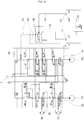
- FIGS. 1 and 2 an apparatus for controlling a combined operations of a construction machine according to an exemplary embodiment of the present disclosure will be described with reference to FIGS. 1 and 2 .
- the apparatus for controlling the combined operations of the construction machine includes a first pump PI, a second pump P2, a driving control spool 20, a swing control spool 30, and a driving priority valve 40.
- the apparatus for controlling the combined operations of the construction machine has the first pump P1 and the second pump P2 in order to perform driving and front operations.
- the first pump P1 Based on an operation of an operating unit 10, the first pump P1 provides pressurized oil to a plurality of actuators for performing the driving and front operations of the construction machine.
- the second pump P2 provides pressurized oil to the plurality of actuators for performing front operations of the construction machine.
- the first pump P1 and the second pump P2 use pressurized oil by appropriately distributing the pressurized oil to the plurality of actuators.
- the front operation means operations such as an operation of moving up/down the boom, arm crowd, bucket crowd/dump, and swing of the construction machine such as an excavator.
- the driving control spool 20 and the swing control spool 30 are installed in a flow path which is connected with the first pump P1 and the second pump P2.
- the driving control spool 20 allows the first pump P1 to communicate with a driving motor 70. That is, the driving control spool 20 controls a flow of the pressurized oil being supplied to the driving motor 70.
- the swing control spool 30 is positioned at a downstream side of the driving control spool 20 and allows the first pump to communicate with a swing motor 80 when the swinging operation is performed by the operating unit 10. That is, the swing control spool 30 controls a flow of the pressurized oil being supplied to the swing motor 80.
- the driving priority valve 40 supplies the pressurized oil discharged from the first pump P1 only to the driving control spool 20, and supplies the pressurized oil discharged from the second pump P2 to the swing control spool 30.
- the driving priority valve 40 may be positioned at a most upstream side of the second pump P2.
- the apparatus for controlling the combined operations of the construction machine according to the exemplary embodiment of the present disclosure may further include a switching valve 50.
- the switching valve 50 provides pressurized oil for switching the driving priority valve 40.
- the direction of the switching valve 50 is changed to one direction by inputted pilot pressure, such that the switching valve 50 provides the pressurized oil to the driving priority valve 40.
- the pilot pressure inputted to the switching valve 50 is generated when the operating unit 10 is operated. If the combined operations of driving and swinging are performed by the operating unit 10, driving pilot pressure and swing pilot pressure are discharged from the operating unit 10.
- the swing pilot pressure discharged from the operating unit 10 is supplied to a lower end of the switching valve 50 through a first supply line 12, and the driving pilot pressure is supplied to one side of the switching valve 50 through a second supply line 14.
- the direction of the switching valve 50 is changed to one direction only when the amount of the driving pilot pressure supplied to one side of the switching valve 50 is larger than pressure preset to the switching valve 50.
- a first shuttle valve 11 may be further provided in the first supply line 12, and a second shuttle valve 13 may be further provided in the second supply line 14.
- the first shuttle valve 11 receives left swing pilot pressure and right swing pilot pressure generated by the swinging operation of the operating unit 10, and selects higher pressure from the inputted left and right swing pilot pressure and supplies the higher pressure to the lower end of the switching valve 50.
- the second shuttle valve 13 receives forward driving (FWD) pilot pressure and reverse driving (REV) pilot pressure generated by the driving operation of the operating unit 10, and selects higher pressure from the inputted forward and reverse driving pilot pressures and supplies the higher pressure to one side of the switching valve 50.
- FWD forward driving
- REV reverse driving
- the swing pilot pressure which is supplied to the lower end of the switching valve 50, is supplied to a first merging line 51 and a second merging line 52.
- the swing pilot pressure supplied to the first merging line 51 is supplied to a bypass valve 60.
- the swing pilot pressure supplied to the second merging line 52 is provided as pressure for switching the driving priority valve 40.
- the bypass valve 60 is positioned at a most downstream side of the second pump P2. Therefore, the second pump P2 and a hydraulic oil tank T are in communication with each other.
- the pressurized oil discharged from the second pump P2 is discharged into the hydraulic oil tank T.
- the pilot pressure supplied to the bypass valve 60 prevents the pressurized oil discharged from the second pump P2 from being discharged into the hydraulic oil tank T.
- bypass valve 60 is switched in accordance with the swing pilot pressure, and as a result, it is possible to variably control the amount of oil being discharged from the second pump P2 into the tank T.
- the structure of the driving priority valve 40 or 41 according to the exemplary embodiment of the present disclosure may be formed as illustrated in FIGS. 1 and 2 or as illustrated in FIGS. 3 and 4 .
- the structure of the driving priority valve 40 is not particularly limited as long as the valve structure is a valve structure in which a flow path is disposed so that when the driving priority valve 40 is switched by the pilot pressure, a part of the pressurized oil discharged from the driving priority valve 40 may be supplied to the swing control spool 30, and the remaining part of the pressurized oil may be discharged into the hydraulic oil tank T.
- the structure of the driving priority valve 40 illustrated in FIGS. 1 to 4 may vary depending on those skilled in the art who implement the present disclosure.
- the first pump P1 is used only to perform the driving operation and the second pump P2 is used to perform the swinging operation when the combined operations of driving and swinging are performed, such that the driving and swinging operations may have no effect on each other, and may use a maximum flow rate (maximum speed).
Landscapes
- Engineering & Computer Science (AREA)
- General Engineering & Computer Science (AREA)
- Physics & Mathematics (AREA)
- Fluid Mechanics (AREA)
- Mining & Mineral Resources (AREA)
- Civil Engineering (AREA)
- Structural Engineering (AREA)
- Mechanical Engineering (AREA)
- Operation Control Of Excavators (AREA)
- Fluid-Pressure Circuits (AREA)
Claims (6)
- Appareil de commande d'opérations combinées d'un engin de chantier, l'appareil comprenant :une pluralité d'actionneurs comprenant un moteur de conduite (70) pour effectuer une opération de conduite et un moteur de pivotement (80) pour effectuer une opération de pivotement ;une unité d'opération (10) ;une première pompe (P1) et une seconde pompe (P2) qui fournissent de l'huile sous pression à la pluralité d'actionneurs pour effectuer des opérations de conduite et de pivotement de l'engin de chantier par une opération de l'unité d'opération (10) ;un tiroir de commande de conduite (20) qui permet à la première pompe (P1) de communiquer avec le moteur de conduite (70) ; etun tiroir de commande de pivotement (30) qui est positionné en aval du tiroir de commande de conduite (20) et permet à la première pompe (P1) de communiquer avec le moteur de pivotement (80),le tiroir de commande de conduite (20) permettant au moteur de conduite (70) de communiquer sélectivement avec la première pompe (P1), et l'appareil comprenant une vanne de priorité de conduite (40) qui permet que l'huile sous pression refoulée par la première pompe (P1) soit fournie uniquement au tiroir de commande de conduite (20) et que l'huile sous pression refoulée par la seconde pompe (P2) soit fournie au tiroir de commande de pivotement (30) lorsque des opérations combinées de conduite et de pivotement de l'engin de chantier sont effectuées.
- Dispositif selon la revendication 1, la vanne de priorité de conduite (40) étant positionnée sur un côté le plus en amont de la seconde pompe (P2).
- Appareil selon la revendication 1, comprenant en outre :
une vanne de commutation (50) qui fournit de l'huile sous pression pour commuter la vanne de priorité de conduite (40). - Appareil selon la revendication 3, la vanne de commutation (50) étant commutée par la pression pilote de conduite refoulée de l'unité d'opération (10) lorsque les opérations combinées de conduite et de pivotement sont effectuées par le fonctionnement de l'unité d'opération (10), et la pression pilote de pivotement refoulée de l'unité d'opération (10) étant fournie vers la vanne de priorité de conduite (40) devant être commutée,
la vanne de commutation (50) n'étant commutée que lorsque la valeur de la pression pilote de conduite fournie à un côté de la vanne de commutation (50) est supérieure à la pression prédéfinie pour la vanne de commutation (50). - Appareil selon la revendication 4, comprenant en outre :une vanne de dérivation (60) qui commande l'huile sous pression refoulée par la seconde pompe (P2),la vanne de commutation (50) fournissant la pression pilote de pivotement pour commuter la vanne de dérivation (60) lorsque les opérations combinées sont effectuées.
- Appareil selon la revendication 5, la vanne de dérivation (60) étant positionnée sur le côté le plus en aval de la seconde pompe (P2), et permettant à la seconde pompe (P2) de communiquer avec un réservoir d'huile hydraulique (T).
Applications Claiming Priority (2)
| Application Number | Priority Date | Filing Date | Title |
|---|---|---|---|
| KR1020130164663A KR102083687B1 (ko) | 2013-12-26 | 2013-12-26 | 건설기계의 복합동작 제어장치 |
| PCT/KR2014/012439 WO2015099352A1 (fr) | 2013-12-26 | 2014-12-17 | Appareil pour commander une opération combinée d'un engin de chantier |
Publications (3)
| Publication Number | Publication Date |
|---|---|
| EP3093401A1 EP3093401A1 (fr) | 2016-11-16 |
| EP3093401A4 EP3093401A4 (fr) | 2017-09-13 |
| EP3093401B1 true EP3093401B1 (fr) | 2019-09-25 |
Family
ID=53479143
Family Applications (1)
| Application Number | Title | Priority Date | Filing Date |
|---|---|---|---|
| EP14873984.0A Active EP3093401B1 (fr) | 2013-12-26 | 2014-12-17 | Appareil pour commander une opération combinée d'un engin de chantier |
Country Status (4)
| Country | Link |
|---|---|
| EP (1) | EP3093401B1 (fr) |
| KR (1) | KR102083687B1 (fr) |
| CN (1) | CN105917052B (fr) |
| WO (1) | WO2015099352A1 (fr) |
Families Citing this family (1)
| Publication number | Priority date | Publication date | Assignee | Title |
|---|---|---|---|---|
| CN110925253B (zh) * | 2019-12-19 | 2021-11-09 | 三一重机有限公司 | 工程机械复合动作控制方法及装置 |
Family Cites Families (12)
| Publication number | Priority date | Publication date | Assignee | Title |
|---|---|---|---|---|
| US4112821A (en) * | 1976-12-03 | 1978-09-12 | Caterpillar Tractor Co. | Fluid control system for multiple circuited work elements |
| JP2776702B2 (ja) * | 1992-09-18 | 1998-07-16 | 新キャタピラー三菱株式会社 | 建設機械の油圧回路 |
| US5940997A (en) * | 1997-09-05 | 1999-08-24 | Hitachi Construction Machinery Co., Ltd. | Hydraulic circuit system for hydraulic working machine |
| KR100797315B1 (ko) * | 2001-07-16 | 2008-01-23 | 두산인프라코어 주식회사 | 굴삭기의 주행 및 프론트작업의 복합작업용 유압제어장치 |
| JP4033849B2 (ja) * | 2004-03-30 | 2008-01-16 | 株式会社カワサキプレシジョンマシナリ | 可変容量型油圧ポンプ制御装置 |
| JP5238181B2 (ja) * | 2007-04-17 | 2013-07-17 | カヤバ工業株式会社 | 油圧ショベル |
| KR100974285B1 (ko) * | 2008-08-12 | 2010-08-06 | 볼보 컨스트럭션 이키프먼트 홀딩 스웨덴 에이비 | 노멀 오픈식 유압 회로 |
| KR20100044585A (ko) * | 2008-10-22 | 2010-04-30 | 볼보 컨스트럭션 이키프먼트 홀딩 스웨덴 에이비 | 선회장치를 구비하는 건설장비용 유압회로 |
| JP2010101095A (ja) | 2008-10-24 | 2010-05-06 | Kobelco Contstruction Machinery Ltd | 作業機械の油圧制御装置 |
| KR101625681B1 (ko) * | 2009-12-23 | 2016-05-30 | 두산인프라코어 주식회사 | 건설기계의 급선회 방지용 유압시스템 |
| CN103998794A (zh) * | 2011-12-15 | 2014-08-20 | 沃尔沃建造设备有限公司 | 用于施工机械的行进控制系统 |
| CN102587445A (zh) * | 2012-03-20 | 2012-07-18 | 龙工(上海)桥箱有限公司 | 一种带有再生节能的负荷传感流量控制液压系统 |
-
2013
- 2013-12-26 KR KR1020130164663A patent/KR102083687B1/ko active Active
-
2014
- 2014-12-17 WO PCT/KR2014/012439 patent/WO2015099352A1/fr not_active Ceased
- 2014-12-17 EP EP14873984.0A patent/EP3093401B1/fr active Active
- 2014-12-17 CN CN201480070227.1A patent/CN105917052B/zh active Active
Non-Patent Citations (1)
| Title |
|---|
| None * |
Also Published As
| Publication number | Publication date |
|---|---|
| CN105917052B (zh) | 2018-11-30 |
| EP3093401A1 (fr) | 2016-11-16 |
| WO2015099352A1 (fr) | 2015-07-02 |
| KR20150076045A (ko) | 2015-07-06 |
| EP3093401A4 (fr) | 2017-09-13 |
| KR102083687B1 (ko) | 2020-04-14 |
| CN105917052A (zh) | 2016-08-31 |
Similar Documents
| Publication | Publication Date | Title |
|---|---|---|
| EP2157245B1 (fr) | Système hydraulique pour équipement de construction. | |
| CN104220763B (zh) | 施工机械的液压回路及其控制装置 | |
| US10107311B2 (en) | Hydraulic drive system for construction machine | |
| JP5669448B2 (ja) | 掘削機用油圧駆動システム | |
| EP3203086B1 (fr) | Circuit hydraulique de machine de construction | |
| JP2010013927A (ja) | 掘削機用油圧駆動システム | |
| KR101190553B1 (ko) | 건설기계의 유압구동장치 | |
| CN102265041A (zh) | 工程机械的液压泵控制装置 | |
| EP2799723B1 (fr) | Système de réduction de consommation de carburant dans une excavatrice | |
| JP6004900B2 (ja) | パワーショベルの流体圧制御装置 | |
| CN105492779A (zh) | 建筑机械的多联换向阀 | |
| EP2853753A1 (fr) | Système hydraulique pour machines de construction | |
| RU2698149C2 (ru) | Гидравлическая система машины и машина | |
| KR20150033928A (ko) | 건설기계의 주행복합작업용 유압제어시스템 | |
| EP3093401B1 (fr) | Appareil pour commander une opération combinée d'un engin de chantier | |
| KR101080173B1 (ko) | 복수개의 컨트롤밸브유닛들이 결합된 굴삭기용 메인컨트롤밸브어셈블리 | |
| JP6012021B2 (ja) | パワーショベルの流体圧制御装置 | |
| RU2678475C2 (ru) | Гидравлическая система с единичной сосредоточенной нагрузкой и машина | |
| KR102088062B1 (ko) | 굴삭기의 주행제어장치 | |
| KR20040045635A (ko) | 소형 굴삭기의 암속도 제어장치 | |
| CN222208443U (zh) | 定、变量双泵合流液压系统及包括该液压系统的工程机械 | |
| JP5455563B2 (ja) | 油圧回路装置 | |
| KR102083034B1 (ko) | 굴삭기의 메인 컨트롤 밸브 | |
| KR101568047B1 (ko) | 굴삭기의 암과 버킷의 유압회로 | |
| RU2668413C2 (ru) | Гидравлическая система для машины, машина и способ управления гидравлической системой |
Legal Events
| Date | Code | Title | Description |
|---|---|---|---|
| PUAI | Public reference made under article 153(3) epc to a published international application that has entered the european phase |
Free format text: ORIGINAL CODE: 0009012 |
|
| 17P | Request for examination filed |
Effective date: 20160726 |
|
| AK | Designated contracting states |
Kind code of ref document: A1 Designated state(s): AL AT BE BG CH CY CZ DE DK EE ES FI FR GB GR HR HU IE IS IT LI LT LU LV MC MK MT NL NO PL PT RO RS SE SI SK SM TR |
|
| AX | Request for extension of the european patent |
Extension state: BA ME |
|
| RIN1 | Information on inventor provided before grant (corrected) |
Inventor name: KONG, HEE SEOG Inventor name: YEO, MYEONG KU Inventor name: KWAK, HONG SUP |
|
| DAX | Request for extension of the european patent (deleted) | ||
| A4 | Supplementary search report drawn up and despatched |
Effective date: 20170817 |
|
| RIC1 | Information provided on ipc code assigned before grant |
Ipc: F15B 13/02 20060101ALI20170810BHEP Ipc: F15B 11/20 20060101ALI20170810BHEP Ipc: E02F 9/22 20060101AFI20170810BHEP |
|
| GRAP | Despatch of communication of intention to grant a patent |
Free format text: ORIGINAL CODE: EPIDOSNIGR1 |
|
| STAA | Information on the status of an ep patent application or granted ep patent |
Free format text: STATUS: GRANT OF PATENT IS INTENDED |
|
| INTG | Intention to grant announced |
Effective date: 20190416 |
|
| GRAS | Grant fee paid |
Free format text: ORIGINAL CODE: EPIDOSNIGR3 |
|
| GRAA | (expected) grant |
Free format text: ORIGINAL CODE: 0009210 |
|
| STAA | Information on the status of an ep patent application or granted ep patent |
Free format text: STATUS: THE PATENT HAS BEEN GRANTED |
|
| AK | Designated contracting states |
Kind code of ref document: B1 Designated state(s): AL AT BE BG CH CY CZ DE DK EE ES FI FR GB GR HR HU IE IS IT LI LT LU LV MC MK MT NL NO PL PT RO RS SE SI SK SM TR |
|
| REG | Reference to a national code |
Ref country code: GB Ref legal event code: FG4D |
|
| REG | Reference to a national code |
Ref country code: CH Ref legal event code: EP |
|
| REG | Reference to a national code |
Ref country code: AT Ref legal event code: REF Ref document number: 1183951 Country of ref document: AT Kind code of ref document: T Effective date: 20191015 |
|
| REG | Reference to a national code |
Ref country code: IE Ref legal event code: FG4D |
|
| REG | Reference to a national code |
Ref country code: DE Ref legal event code: R096 Ref document number: 602014054371 Country of ref document: DE |
|
| REG | Reference to a national code |
Ref country code: NL Ref legal event code: MP Effective date: 20190925 |
|
| PG25 | Lapsed in a contracting state [announced via postgrant information from national office to epo] |
Ref country code: SE Free format text: LAPSE BECAUSE OF FAILURE TO SUBMIT A TRANSLATION OF THE DESCRIPTION OR TO PAY THE FEE WITHIN THE PRESCRIBED TIME-LIMIT Effective date: 20190925 Ref country code: BG Free format text: LAPSE BECAUSE OF FAILURE TO SUBMIT A TRANSLATION OF THE DESCRIPTION OR TO PAY THE FEE WITHIN THE PRESCRIBED TIME-LIMIT Effective date: 20191225 Ref country code: NO Free format text: LAPSE BECAUSE OF FAILURE TO SUBMIT A TRANSLATION OF THE DESCRIPTION OR TO PAY THE FEE WITHIN THE PRESCRIBED TIME-LIMIT Effective date: 20191225 Ref country code: FI Free format text: LAPSE BECAUSE OF FAILURE TO SUBMIT A TRANSLATION OF THE DESCRIPTION OR TO PAY THE FEE WITHIN THE PRESCRIBED TIME-LIMIT Effective date: 20190925 Ref country code: HR Free format text: LAPSE BECAUSE OF FAILURE TO SUBMIT A TRANSLATION OF THE DESCRIPTION OR TO PAY THE FEE WITHIN THE PRESCRIBED TIME-LIMIT Effective date: 20190925 Ref country code: LT Free format text: LAPSE BECAUSE OF FAILURE TO SUBMIT A TRANSLATION OF THE DESCRIPTION OR TO PAY THE FEE WITHIN THE PRESCRIBED TIME-LIMIT Effective date: 20190925 |
|
| REG | Reference to a national code |
Ref country code: LT Ref legal event code: MG4D |
|
| PG25 | Lapsed in a contracting state [announced via postgrant information from national office to epo] |
Ref country code: RS Free format text: LAPSE BECAUSE OF FAILURE TO SUBMIT A TRANSLATION OF THE DESCRIPTION OR TO PAY THE FEE WITHIN THE PRESCRIBED TIME-LIMIT Effective date: 20190925 Ref country code: LV Free format text: LAPSE BECAUSE OF FAILURE TO SUBMIT A TRANSLATION OF THE DESCRIPTION OR TO PAY THE FEE WITHIN THE PRESCRIBED TIME-LIMIT Effective date: 20190925 Ref country code: GR Free format text: LAPSE BECAUSE OF FAILURE TO SUBMIT A TRANSLATION OF THE DESCRIPTION OR TO PAY THE FEE WITHIN THE PRESCRIBED TIME-LIMIT Effective date: 20191226 |
|
| REG | Reference to a national code |
Ref country code: AT Ref legal event code: MK05 Ref document number: 1183951 Country of ref document: AT Kind code of ref document: T Effective date: 20190925 |
|
| PG25 | Lapsed in a contracting state [announced via postgrant information from national office to epo] |
Ref country code: PT Free format text: LAPSE BECAUSE OF FAILURE TO SUBMIT A TRANSLATION OF THE DESCRIPTION OR TO PAY THE FEE WITHIN THE PRESCRIBED TIME-LIMIT Effective date: 20200127 Ref country code: ES Free format text: LAPSE BECAUSE OF FAILURE TO SUBMIT A TRANSLATION OF THE DESCRIPTION OR TO PAY THE FEE WITHIN THE PRESCRIBED TIME-LIMIT Effective date: 20190925 Ref country code: AL Free format text: LAPSE BECAUSE OF FAILURE TO SUBMIT A TRANSLATION OF THE DESCRIPTION OR TO PAY THE FEE WITHIN THE PRESCRIBED TIME-LIMIT Effective date: 20190925 Ref country code: EE Free format text: LAPSE BECAUSE OF FAILURE TO SUBMIT A TRANSLATION OF THE DESCRIPTION OR TO PAY THE FEE WITHIN THE PRESCRIBED TIME-LIMIT Effective date: 20190925 Ref country code: PL Free format text: LAPSE BECAUSE OF FAILURE TO SUBMIT A TRANSLATION OF THE DESCRIPTION OR TO PAY THE FEE WITHIN THE PRESCRIBED TIME-LIMIT Effective date: 20190925 Ref country code: IT Free format text: LAPSE BECAUSE OF FAILURE TO SUBMIT A TRANSLATION OF THE DESCRIPTION OR TO PAY THE FEE WITHIN THE PRESCRIBED TIME-LIMIT Effective date: 20190925 Ref country code: AT Free format text: LAPSE BECAUSE OF FAILURE TO SUBMIT A TRANSLATION OF THE DESCRIPTION OR TO PAY THE FEE WITHIN THE PRESCRIBED TIME-LIMIT Effective date: 20190925 Ref country code: NL Free format text: LAPSE BECAUSE OF FAILURE TO SUBMIT A TRANSLATION OF THE DESCRIPTION OR TO PAY THE FEE WITHIN THE PRESCRIBED TIME-LIMIT Effective date: 20190925 Ref country code: RO Free format text: LAPSE BECAUSE OF FAILURE TO SUBMIT A TRANSLATION OF THE DESCRIPTION OR TO PAY THE FEE WITHIN THE PRESCRIBED TIME-LIMIT Effective date: 20190925 |
|
| PG25 | Lapsed in a contracting state [announced via postgrant information from national office to epo] |
Ref country code: IS Free format text: LAPSE BECAUSE OF FAILURE TO SUBMIT A TRANSLATION OF THE DESCRIPTION OR TO PAY THE FEE WITHIN THE PRESCRIBED TIME-LIMIT Effective date: 20200224 Ref country code: CZ Free format text: LAPSE BECAUSE OF FAILURE TO SUBMIT A TRANSLATION OF THE DESCRIPTION OR TO PAY THE FEE WITHIN THE PRESCRIBED TIME-LIMIT Effective date: 20190925 Ref country code: SK Free format text: LAPSE BECAUSE OF FAILURE TO SUBMIT A TRANSLATION OF THE DESCRIPTION OR TO PAY THE FEE WITHIN THE PRESCRIBED TIME-LIMIT Effective date: 20190925 Ref country code: SM Free format text: LAPSE BECAUSE OF FAILURE TO SUBMIT A TRANSLATION OF THE DESCRIPTION OR TO PAY THE FEE WITHIN THE PRESCRIBED TIME-LIMIT Effective date: 20190925 |
|
| REG | Reference to a national code |
Ref country code: DE Ref legal event code: R097 Ref document number: 602014054371 Country of ref document: DE |
|
| PG2D | Information on lapse in contracting state deleted |
Ref country code: IS |
|
| PG25 | Lapsed in a contracting state [announced via postgrant information from national office to epo] |
Ref country code: DK Free format text: LAPSE BECAUSE OF FAILURE TO SUBMIT A TRANSLATION OF THE DESCRIPTION OR TO PAY THE FEE WITHIN THE PRESCRIBED TIME-LIMIT Effective date: 20190925 Ref country code: IS Free format text: LAPSE BECAUSE OF FAILURE TO SUBMIT A TRANSLATION OF THE DESCRIPTION OR TO PAY THE FEE WITHIN THE PRESCRIBED TIME-LIMIT Effective date: 20200126 |
|
| PLBE | No opposition filed within time limit |
Free format text: ORIGINAL CODE: 0009261 |
|
| REG | Reference to a national code |
Ref country code: CH Ref legal event code: PL |
|
| STAA | Information on the status of an ep patent application or granted ep patent |
Free format text: STATUS: NO OPPOSITION FILED WITHIN TIME LIMIT |
|
| REG | Reference to a national code |
Ref country code: BE Ref legal event code: MM Effective date: 20191231 |
|
| PG25 | Lapsed in a contracting state [announced via postgrant information from national office to epo] |
Ref country code: MC Free format text: LAPSE BECAUSE OF FAILURE TO SUBMIT A TRANSLATION OF THE DESCRIPTION OR TO PAY THE FEE WITHIN THE PRESCRIBED TIME-LIMIT Effective date: 20190925 |
|
| 26N | No opposition filed |
Effective date: 20200626 |
|
| PG25 | Lapsed in a contracting state [announced via postgrant information from national office to epo] |
Ref country code: IE Free format text: LAPSE BECAUSE OF NON-PAYMENT OF DUE FEES Effective date: 20191217 Ref country code: LU Free format text: LAPSE BECAUSE OF NON-PAYMENT OF DUE FEES Effective date: 20191217 |
|
| PG25 | Lapsed in a contracting state [announced via postgrant information from national office to epo] |
Ref country code: CH Free format text: LAPSE BECAUSE OF NON-PAYMENT OF DUE FEES Effective date: 20191231 Ref country code: BE Free format text: LAPSE BECAUSE OF NON-PAYMENT OF DUE FEES Effective date: 20191231 Ref country code: LI Free format text: LAPSE BECAUSE OF NON-PAYMENT OF DUE FEES Effective date: 20191231 Ref country code: SI Free format text: LAPSE BECAUSE OF FAILURE TO SUBMIT A TRANSLATION OF THE DESCRIPTION OR TO PAY THE FEE WITHIN THE PRESCRIBED TIME-LIMIT Effective date: 20190925 |
|
| PG25 | Lapsed in a contracting state [announced via postgrant information from national office to epo] |
Ref country code: CY Free format text: LAPSE BECAUSE OF FAILURE TO SUBMIT A TRANSLATION OF THE DESCRIPTION OR TO PAY THE FEE WITHIN THE PRESCRIBED TIME-LIMIT Effective date: 20190925 |
|
| PG25 | Lapsed in a contracting state [announced via postgrant information from national office to epo] |
Ref country code: HU Free format text: LAPSE BECAUSE OF FAILURE TO SUBMIT A TRANSLATION OF THE DESCRIPTION OR TO PAY THE FEE WITHIN THE PRESCRIBED TIME-LIMIT; INVALID AB INITIO Effective date: 20141217 Ref country code: MT Free format text: LAPSE BECAUSE OF FAILURE TO SUBMIT A TRANSLATION OF THE DESCRIPTION OR TO PAY THE FEE WITHIN THE PRESCRIBED TIME-LIMIT Effective date: 20190925 |
|
| REG | Reference to a national code |
Ref country code: DE Ref legal event code: R081 Ref document number: 602014054371 Country of ref document: DE Owner name: HYUNDAI DOOSAN INFRACORE CO., LTD., KR Free format text: FORMER OWNER: DOOSAN INFRACORE CO., LTD., INCHEON, KR Ref country code: DE Ref legal event code: R081 Ref document number: 602014054371 Country of ref document: DE Owner name: HD HYUNDAI INFRACORE CO., LTD., KR Free format text: FORMER OWNER: DOOSAN INFRACORE CO., LTD., INCHEON, KR |
|
| PG25 | Lapsed in a contracting state [announced via postgrant information from national office to epo] |
Ref country code: TR Free format text: LAPSE BECAUSE OF FAILURE TO SUBMIT A TRANSLATION OF THE DESCRIPTION OR TO PAY THE FEE WITHIN THE PRESCRIBED TIME-LIMIT Effective date: 20190925 |
|
| PG25 | Lapsed in a contracting state [announced via postgrant information from national office to epo] |
Ref country code: MK Free format text: LAPSE BECAUSE OF FAILURE TO SUBMIT A TRANSLATION OF THE DESCRIPTION OR TO PAY THE FEE WITHIN THE PRESCRIBED TIME-LIMIT Effective date: 20190925 |
|
| REG | Reference to a national code |
Ref country code: DE Ref legal event code: R081 Ref document number: 602014054371 Country of ref document: DE Owner name: HD HYUNDAI INFRACORE CO., LTD., KR Free format text: FORMER OWNER: HYUNDAI DOOSAN INFRACORE CO., LTD., INCHEON, KR |
|
| PGFP | Annual fee paid to national office [announced via postgrant information from national office to epo] |
Ref country code: DE Payment date: 20251022 Year of fee payment: 12 |
|
| PGFP | Annual fee paid to national office [announced via postgrant information from national office to epo] |
Ref country code: GB Payment date: 20251023 Year of fee payment: 12 |
|
| PGFP | Annual fee paid to national office [announced via postgrant information from national office to epo] |
Ref country code: FR Payment date: 20251023 Year of fee payment: 12 |