EP3093445B1 - Aube statorique d'une turbine á gaz et procédé de fabrication associé - Google Patents
Aube statorique d'une turbine á gaz et procédé de fabrication associé Download PDFInfo
- Publication number
- EP3093445B1 EP3093445B1 EP16169048.2A EP16169048A EP3093445B1 EP 3093445 B1 EP3093445 B1 EP 3093445B1 EP 16169048 A EP16169048 A EP 16169048A EP 3093445 B1 EP3093445 B1 EP 3093445B1
- Authority
- EP
- European Patent Office
- Prior art keywords
- chordal seal
- chordal
- airfoil
- seal
- pair
- Prior art date
- Legal status (The legal status is an assumption and is not a legal conclusion. Google has not performed a legal analysis and makes no representation as to the accuracy of the status listed.)
- Active
Links
Images

Classifications
-
- F—MECHANICAL ENGINEERING; LIGHTING; HEATING; WEAPONS; BLASTING
- F01—MACHINES OR ENGINES IN GENERAL; ENGINE PLANTS IN GENERAL; STEAM ENGINES
- F01D—NON-POSITIVE DISPLACEMENT MACHINES OR ENGINES, e.g. STEAM TURBINES
- F01D9/00—Stators
- F01D9/02—Nozzles; Nozzle boxes; Stator blades; Guide conduits, e.g. individual nozzles
- F01D9/04—Nozzles; Nozzle boxes; Stator blades; Guide conduits, e.g. individual nozzles forming ring or sector
- F01D9/042—Nozzles; Nozzle boxes; Stator blades; Guide conduits, e.g. individual nozzles forming ring or sector fixing blades to stators
-
- F—MECHANICAL ENGINEERING; LIGHTING; HEATING; WEAPONS; BLASTING
- F01—MACHINES OR ENGINES IN GENERAL; ENGINE PLANTS IN GENERAL; STEAM ENGINES
- F01D—NON-POSITIVE DISPLACEMENT MACHINES OR ENGINES, e.g. STEAM TURBINES
- F01D11/00—Preventing or minimising internal leakage of working-fluid, e.g. between stages
- F01D11/005—Sealing means between non relatively rotating elements
- F01D11/006—Sealing the gap between rotor blades or blades and rotor
-
- F—MECHANICAL ENGINEERING; LIGHTING; HEATING; WEAPONS; BLASTING
- F01—MACHINES OR ENGINES IN GENERAL; ENGINE PLANTS IN GENERAL; STEAM ENGINES
- F01D—NON-POSITIVE DISPLACEMENT MACHINES OR ENGINES, e.g. STEAM TURBINES
- F01D25/00—Component parts, details, or accessories, not provided for in, or of interest apart from, other groups
- F01D25/24—Casings; Casing parts, e.g. diaphragms, casing fastenings
- F01D25/246—Fastening of diaphragms or stator-rings
-
- F—MECHANICAL ENGINEERING; LIGHTING; HEATING; WEAPONS; BLASTING
- F05—INDEXING SCHEMES RELATING TO ENGINES OR PUMPS IN VARIOUS SUBCLASSES OF CLASSES F01-F04
- F05D—INDEXING SCHEME FOR ASPECTS RELATING TO NON-POSITIVE-DISPLACEMENT MACHINES OR ENGINES, GAS-TURBINES OR JET-PROPULSION PLANTS
- F05D2240/00—Components
- F05D2240/55—Seals
- F05D2240/57—Leaf seals
Definitions
- the present invention relates to a vane for a gas turbine engine and a corresponding method for forming a vane for a gas turbine engine.
- a gas turbine engine typically includes a fan section, a compressor section, a combustor section, and a turbine section. Air entering the compressor section is compressed and delivered into the combustion section where it is mixed with fuel and ignited to generate a high-speed exhaust gas flow. The high-speed exhaust gas flow expands through the turbine section to drive the compressor and the fan section.
- Gas turbine stator vane assemblies typically include a plurality of vane segments which collectively form the annular vane assembly.
- Each vane segment includes one or more airfoils extending between an outer platform and an inner platform.
- the inner and outer platforms collectively provide radial boundaries to guide core gas flow past the airfoils.
- Core gas flow may be defined as gas exiting the compressor passing directly through the combustor and entering the turbine.
- Vane support rings support and position each vane segment radially inside of the engine diffuser case.
- cooling air bled off of the fan is directed into an annular region between the diffuser case and an outer case, and a percentage of compressor air is directed in the annular region between the outer platforms and the diffuser case, and the annular region radially inside of the inner platforms.
- the fan air is at a lower temperature than the compressor air, and consequently cools the diffuser case and the compressor air enclosed therein.
- the compressor air is at a higher pressure and lower temperature than the core gas flow which passes on to the turbine.
- the higher pressure compressor air prevents the hot core gas flow from escaping the core gas flow path between the platforms.
- the lower temperature of the compressor flow keeps the annular regions radially inside and outside of the vane segments cool relative to the core gas flow.
- EP 1057975 A2 discloses a prior art vane set forth in the preamble of claim 1.
- EP0343361A1 discloses a vane for a gas turbine engine comprising a first airfoil, a first chordal seal located adjacent a first end of the first airfoil, wherein the first chordal seal is located on a rail located on an opposite side of a first platform from the first airfoil and a first pair of transition regions which extend along a pair of edges of the first chordal seal, a second chordal seal located adjacent a second end of the first airfoil, wherein the first chordal seal includes a first edge parallel to a first edge on the second chordal seal and a cusp of material spaced radially inward from the first chordal seal.
- US 3909155 A1 discloses a prior art nozzle guide vane assembly.
- the first chordal seal includes a second edge parallel to a second edge on the second chordal seal.
- a second pair of transition regions extends along a pair of edges of the second chordal seal.
- first airfoil and the second airfoil extend between the first platform located at a first end of the first and second airfoils.
- a second platform is located at a second end of the first and second airfoils.
- a second edge of the first chordal seal adjacent the first end of the airfoil is machined while the component is attached to the fixture.
- a second edge of the second chordal seal adjacent the second end of the airfoil is machined while the component is attached to the fixture.
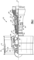
- FIG. 1 schematically illustrates a gas turbine engine 20.
- the gas turbine engine 20 is disclosed herein as a two-spool turbofan that generally incorporates a fan section 22, a compressor section 24, a combustor section 26 and a turbine section 28.
- Alternative engines might include an augmentor section (not shown) among other systems or features.
- the fan section 22 drives air along a bypass flow path B in a bypass duct defined within a nacelle 15, while the compressor section 24 drives air along a core flow path C for compression and communication into the combustor section 26 then expansion through the turbine section 28.
- the exemplary engine 20 generally includes a low speed spool 30 and a high speed spool 32 mounted for rotation about an engine central longitudinal axis A relative to an engine static structure 36 via several bearing systems 38. It should be understood that various bearing systems 38 at various locations may alternatively or additionally be provided, and the location of bearing systems 38 may be varied as appropriate to the application.
- the low speed spool 30 generally includes an inner shaft 40 that interconnects a fan 42, a first (or low) pressure compressor 44 and a first (or low) pressure turbine 46.
- the inner shaft 40 is connected to the fan 42 through a speed change mechanism, which in exemplary gas turbine engine 20 is illustrated as a geared architecture 48 to drive the fan 42 at a lower speed than the low speed spool 30.
- the high speed spool 32 includes an outer shaft 50 that interconnects a second (or high) pressure compressor 52 and a second (or high) pressure turbine 54.
- a combustor 56 is arranged in exemplary gas turbine 20 between the high pressure compressor 52 and the high pressure turbine 54.
- a mid-turbine frame 57 of the engine static structure 36 is arranged generally between the high pressure turbine 54 and the low pressure turbine 46.
- the mid-turbine frame 57 further supports bearing systems 38 in the turbine section 28.
- the inner shaft 40 and the outer shaft 50 are concentric and rotate via bearing systems 38 about the engine central longitudinal axis A which is collinear with their longitudinal axes.
- the core airflow is compressed by the low pressure compressor 44 then the high pressure compressor 52, mixed and burned with fuel in the combustor 56, then expanded over the high pressure turbine 54 and low pressure turbine 46.
- the mid-turbine frame 57 includes airfoils 59 which are in the core airflow path C.
- the turbines 46, 54 rotationally drive the respective low speed spool 30 and high speed spool 32 in response to the expansion.
- gear system 48 may be located aft of combustor section 26 or even aft of turbine section 28, and fan section 22 may be positioned forward or aft of the location of gear system 48.
- the engine 20 in one example is a high-bypass geared aircraft engine.
- the engine 20 bypass ratio is greater than about six (6:1), with an example embodiment being greater than about ten (10:1)
- the geared architecture 48 is an epicyclic gear train, such as a planetary gear system or other gear system, with a gear reduction ratio of greater than about 2.3:1
- the low pressure turbine 46 has a pressure ratio that is greater than about five.
- the engine 20 bypass ratio is greater than about ten
- the fan diameter is significantly larger than that of the low pressure compressor 44
- the low pressure turbine 46 has a pressure ratio that is greater than about five.
- Low pressure turbine 46 pressure ratio is pressure measured prior to inlet of low pressure turbine 46 as related to the pressure at the outlet of the low pressure turbine 46 prior to an exhaust nozzle.
- the geared architecture 48 may be an epicycle gear train, such as a planetary gear system or other gear system, with a gear reduction ratio of greater than about 2.3:1. It should be understood, however, that the above parameters are only exemplary of one embodiment of a geared architecture engine and that the present invention is applicable to other gas turbine engines including direct drive turbofans.
- the fan section 22 of the engine 20 is designed for a particular flight condition -- typically cruise at about 0.8 Mach and about 10,668 m (35,000 feet) .
- the flight condition of 0.8 Mach and 10,668 m (35,000 ft), with the engine at its best fuel consumption - also known as "bucket cruise Thrust Specific Fuel Consumption ('TSFC')" - is the industry standard parameter of lbm of fuel being burned divided by lbf of thrust the engine produces at that minimum point.
- "Low fan pressure ratio” is the pressure ratio across the fan blade alone, without a Fan Exit Guide Vane (“FEGV”) system.
- the low fan pressure ratio as disclosed herein according to one non-limiting embodiment is less than about 1.45.
- the "Low corrected fan tip speed” as disclosed herein according to one non-limiting embodiment is less than about 350.5 m/s (1150 ft / second) .
- the example gas turbine engine includes fan 42 that comprises in one non-limiting embodiment less than about twenty-six fan blades. In another non-limiting embodiment, fan section 22 includes less than about twenty fan blades. Moreover, in one disclosed embodiment low pressure turbine 46 includes no more than about six turbine rotors. In another non-limiting example embodiment low pressure turbine 46 includes about three turbine rotors. A ratio between number of fan blades 42 and the number of low pressure turbine rotors is between about 3.3 and about 8.6. The example low pressure turbine 46 provides the driving power to rotate fan section 22 and therefore the relationship between the number of turbine rotors in low pressure turbine 46 and number of blades 42 in fan section 22 disclose an example gas turbine engine 20 with increased power transfer efficiency.
- Figure 2 illustrates an enlarged schematic view of the high pressure turbine 54, however, other sections of the gas turbine engine 20 could benefit from this disclosure.
- the high pressure turbine 54 includes a one-stage turbine section with a first rotor assembly 60.
- the high pressure turbine 54 could include a two-stage high pressure turbine section.
- the first rotor assembly 60 includes a first array of rotor blades 62 circumferentially spaced around a first disk 64.
- Each of the first array of rotor blades 62 includes a first root portion 72, a first platform 76, and a first airfoil 80.
- Each of the first root portions 72 is received within a respective first rim 68 of the first disk 64.
- the first airfoil 80 extends radially outward toward a first blade outer air seal (BOAS) assembly 84.
- BOAS blade outer air seal
- the first array of rotor blades 62 are disposed in the core flow path that is pressurized in the compressor section 24 then heated to a working temperature in the combustor section 26.
- the first platform 76 separates a gas path side inclusive of the first airfoils 80 and a non-gas path side inclusive of the first root portion 72.
- An array of vanes 90 are located axially upstream of the first array of rotor blades 62.
- Each of the array of vanes 90 include at least one airfoil 92 that extend between a respective vane inner platform 94 and an vane outer platform 96.
- each of the array of vanes 90 include at least two airfoils 92 forming a vane double.
- the vane outer platform 96 of the vane 90 may at least partially engage the BOAS 84.
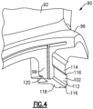
- the vane 90 includes a first chordal seal 102 and a second chordal seal 100 on an axially downstream end of the vane 90.
- the first and second chordal seals 102, 100 are inner and outer chordal seals respectively.
- axial or axially extending is in relation to the axis A of the gas turbine engine 20.
- the outer chordal seal 100 creates a seal between the vane 90 and the BOAS 84.
- the outer chordal seal 100 extends in a chordal direction along an axially facing surface 104 of an outer rail 98.
- the outer rail 98 extends radially outward from the vane outer platform 96.
- the outer chordal seal 100 includes an axially facing surface 106 that faces axially downstream relative to the axis A of the gas turbine engine 20.
- the axially facing surface 106 is axially spaced from the axially facing surface 104 by a pair of transition regions 108.
- the pair of transition regions 108 includes a pair of fillets having a radius of curvature.
- the inner chordal seal 102 creates a seal between the vane 90 and a portion of the static structure 36.
- the inner chordal seal 102 extends in a chordal direction along an axially facing surface 114 of an inner rail 99 extending radially inward from the vane inner platform 94.
- the inner chordal seal 102 will be straight and extend between opposing circumferential ends of the vane inner platform 94.
- the portion of the static structure 36 creating the seal with the inner chordal seal 102 is a flange 110 on a tangent on board injector (TOBI).
- TOBI tangent on board injector
- another portion of the static structure 36 could be used to engage the inner chordal seal 102.
- the inner chordal seal 102 includes an axially facing surface 112 that faces axially downstream relative to the axis A of the gas turbine engine 20.
- the axially facing surface 112 is spaced from the axially facing surface 114 by a pair of transition regions 116.
- the pair of transition regions 116 includes a pair of fillets having a radius of curvature.
- a cusp 118 is located on a radially inner portion of the inner rail 99.
- the cusp 118 is at least partially defined by one of the transition regions 116 along an axially downstream edge and by a recess 120 along an axially forward edge.
- the recess 120 includes a pair of angled surfaces.
- the recess 120 could include a fillet having a radius of curvature.
- Axial positions of the outer chordal seal 100 and the inner chordal seal 102 may vary slightly from one another due to manufacturing tolerances and nominal dimensions of the vane 90 in a cold state. Because of the variations in the vane 90, corresponding pairs of edges on the outer chordal seal 100 and inner chordal seal 102 would engage the BOAS 84 and the flange 110, respectively, and form the seal.
- a first edge 100a of the outer chordal seal 100 engages the BOAS 84 and a first edge 102a of the inner chordal seal 102 engages the flange 110.
- a second edge 100b of the outer chordal seal 100 engages the BOAS 84 and a second edge 102b of the inner chordal seal 102 engages the flange 110.
- the first edges 100a, 102a are located on a radially outer side of the outer chordal seal 100 and the inner chordal seal 102, respectively, and the second edges 100b, 102b are located on a radially inner side of the outer chordal seal 100 and the inner chordal seal 102, respectively.
- the first edge 100a must be parallel to the first edge 102a and the second edge 100b must be parallel to the second edge 102b.
- the corresponding edges are able to maintain a line of contact with the BOAS 84 and static structure 36, respectively, when the deflection between the static structure 36 attached to the vane outer platform 96 and the static structure 36 attached to inner platform 94 varies.
- the first edges 100a, 102a and the second edges 100b, 102b are formed during the same machining process.
- variations in parallelism between the first edges 100a, 102a and the second edges 100b, 102b are reduced.
- the variations in parallelism are reduced because the vane 90 does not need to be mounted into a second jig which can reduce parallelism if the vane 90 is not aligned perfectly in the second jig.
Landscapes
- Engineering & Computer Science (AREA)
- Mechanical Engineering (AREA)
- General Engineering & Computer Science (AREA)
- Turbine Rotor Nozzle Sealing (AREA)
Claims (7)
- Aube statorique (90) pour un moteur à turbine à gaz (20), comprenant :un premier profil aérodynamique (92) ;un premier joint de corde (102) situé à proximité d'une première extrémité du premier profil aérodynamique (92), dans laquelle le premier joint de corde (102) est situé sur un rail (99) situé sur un côté opposé d'une première plate-forme (94) par rapport au premier profil aérodynamique (92) et une première paire de régions de transition (116) se prolongent le long d'une paire de bords du premier joint de corde (102) ;un second joint de corde (100) situé à proximité d'une seconde extrémité du premier profil aérodynamique (92), dans laquelle le premier joint de corde (102) comporte un premier bord (102a) parallèle à un premier bord (100a) sur le second joint de corde (100) ; etune pointe de matériau (118) espacée radialement vers l'intérieur à partir du premier joint de corde (102) ;caractérisée en comprenant également :un évidement (120) dans le rail (99) sur un côté opposé de la pointe de matériau (118) par rapport au premier joint de corde (102), dans laquelle la pointe de matériau (118) est définie par l'une de la première paire de régions de transition (116) le long d'un bord axialement en aval de la pointe de matériau (118) et par l'évidement (120) le long d'un bord axialement en avant de la pointe de matériau (118) ; etdans laquelle le second joint de corde (100) se prolonge dans une direction de corde le long d'une surface orientée axialement (104) d'un rail externe (98), le second joint de corde (100) comporte une surface orientée axialement (106) qui est configurée pour faire face axialement en aval par rapport à un axe (A) du moteur à turbine à gaz (20), et la surface orientée axialement (106) est espacée axialement de la surface orientée axialement (104) par une seconde paire de régions de transition (108), dans laquelle la première et la seconde paire de régions de transition (116, 108) comportent chacune une paire de congés ayant un rayon de courbure.
- Aube statorique (90) selon la revendication 1, dans laquelle le premier joint de corde (102) comporte un second bord (102b) parallèle à un second bord (100b) sur le second joint de corde (100) .
- Aube statorique (90) selon une quelconque revendication précédente, dans laquelle la seconde paire de régions de transition (108) se prolongent le long d'une paire de bords du second joint de corde (100).
- Aube statorique (90) selon une quelconque revendication précédente, comprenant également un second profil aérodynamique, dans laquelle le premier profil aérodynamique (92) et le second profil aérodynamique se prolongent entre une première plate-forme (94) située à une première extrémité des premier et second profils aérodynamiques (92) et une seconde plate-forme (96) située à une seconde extrémité des premier et second profils aérodynamiques (92).
- Aube statorique (90) selon l'une quelconque des revendications 1 à 3, dans laquelle le premier profil aérodynamique (92) se prolonge entre une plate-forme interne (94) et une plate-forme externe (96), le premier joint de corde (102) est situé à proximité de la plate-forme interne (94), et le second joint de corde (100) est situé à proximité de la plate-forme externe (96).
- Procédé de fabrication d'une aube statorique (90) pour un moteur à turbine à gaz (20) comprenant :la fixation d'un profil aérodynamique (92) à un dispositif de fixation ;l'usinage d'un premier bord (102a) d'un premier joint de corde (102) situé à proximité d'une première extrémité du profil aérodynamique (92) pendant que le composant est fixé au dispositif de fixation, dans lequel le premier joint de corde (102) est situé sur un rail (99) situé sur un côté opposé d'une première plate-forme (94) par rapport au premier profil aérodynamique (92) et une première paire de régions de transition (116) se prolongent le long d'une paire de bords du premier joint de corde (102) ;l'usinage d'un premier bord (100a) d'un second joint de corde (100) adjacent à une seconde extrémité du profil aérodynamique (92) pendant que le composant est fixé au dispositif de fixation ;la fabrication d'une pointe (118) espacée radialement vers l'intérieur à partir du premier joint de corde (102) ; etcaractérisé par la fabrication d'un évidement (120) dans le rail (99) sur un côté opposé de la pointe (118) par rapport au premier joint de corde (102), dans lequel le premier bord (102a) du premier joint de corde (102) est parallèle au premier bord (100a) du second joint de corde (100), et la pointe de matériau (118) est définie par l'une de la première paire de régions de transition (116) le long d'un bord axialement en aval de la pointe de matériau (118) et par l'évidement (120) le long d'un bord axialement en avant de la pointe de matériau (118),dans lequel le second joint de corde (100) se prolonge dans une direction de corde le long d'une surface orientée axialement (104) d'un rail externe (98), le second joint de corde (100) comporte une surface orientée axialement (106) qui est configurée pour faire face axialement en aval par rapport à un axe (A) du moteur à turbine à gaz (20), et la surface orientée axialement (106) est espacée axialement de la surface orientée axialement (104) par une seconde paire de régions de transition (108), dans lequel la première et la seconde paire de régions de transition (116, 108) comportent chacune une paire de congés ayant un rayon de courbure.
- Procédé selon la revendication 6, comprenant également :l'usinage d'un second bord (102b) du premier joint de corde (102) adjacent à la première extrémité du profil aérodynamique (92) pendant que le composant est fixé au dispositif de fixation ; etl'usinage d'un second bord (100b) du second joint de corde (100) adjacent à une seconde extrémité du profil aérodynamique (92) pendant que le composant est fixé au dispositif de fixation.
Applications Claiming Priority (1)
| Application Number | Priority Date | Filing Date | Title |
|---|---|---|---|
| US14/708,939 US9863259B2 (en) | 2015-05-11 | 2015-05-11 | Chordal seal |
Publications (2)
| Publication Number | Publication Date |
|---|---|
| EP3093445A1 EP3093445A1 (fr) | 2016-11-16 |
| EP3093445B1 true EP3093445B1 (fr) | 2024-11-06 |
Family
ID=55963229
Family Applications (1)
| Application Number | Title | Priority Date | Filing Date |
|---|---|---|---|
| EP16169048.2A Active EP3093445B1 (fr) | 2015-05-11 | 2016-05-10 | Aube statorique d'une turbine á gaz et procédé de fabrication associé |
Country Status (2)
| Country | Link |
|---|---|
| US (1) | US9863259B2 (fr) |
| EP (1) | EP3093445B1 (fr) |
Families Citing this family (9)
| Publication number | Priority date | Publication date | Assignee | Title |
|---|---|---|---|---|
| US10808612B2 (en) * | 2015-05-29 | 2020-10-20 | Raytheon Technologies Corporation | Retaining tab for diffuser seal ring |
| US10329937B2 (en) * | 2016-09-16 | 2019-06-25 | United Technologies Corporation | Flowpath component for a gas turbine engine including a chordal seal |
| US10557360B2 (en) * | 2016-10-17 | 2020-02-11 | United Technologies Corporation | Vane intersegment gap sealing arrangement |
| US10519807B2 (en) | 2017-04-19 | 2019-12-31 | Rolls-Royce Corporation | Seal segment retention ring with chordal seal feature |
| FR3074840B1 (fr) * | 2017-12-11 | 2021-01-08 | Safran Aircraft Engines | Distributeur de turbomachine a etancheite amelioree |
| US10927692B2 (en) * | 2018-08-06 | 2021-02-23 | General Electric Company | Turbomachinery sealing apparatus and method |
| US10968777B2 (en) * | 2019-04-24 | 2021-04-06 | Raytheon Technologies Corporation | Chordal seal |
| US11346234B2 (en) | 2020-01-02 | 2022-05-31 | Rolls-Royce Plc | Turbine vane assembly incorporating ceramic matrix composite materials |
| US11732596B2 (en) | 2021-12-22 | 2023-08-22 | Rolls-Royce Plc | Ceramic matrix composite turbine vane assembly having minimalistic support spars |
Citations (2)
| Publication number | Priority date | Publication date | Assignee | Title |
|---|---|---|---|---|
| US6568903B1 (en) * | 2001-12-28 | 2003-05-27 | General Electric Company | Supplemental seal for the chordal hinge seals in a gas turbine |
| EP3091199A1 (fr) * | 2015-05-07 | 2016-11-09 | United Technologies Corporation | Profil et aube statorique associée |
Family Cites Families (19)
| Publication number | Priority date | Publication date | Assignee | Title |
|---|---|---|---|---|
| GB1385666A (en) | 1973-07-06 | 1975-02-26 | Rolls Royce | Sealing of vaned assemblies of gas turbine engines |
| US4194869A (en) * | 1978-06-29 | 1980-03-25 | United Technologies Corporation | Stator vane cluster |
| DE3003470C2 (de) * | 1980-01-31 | 1982-02-25 | MTU Motoren- und Turbinen-Union München GmbH, 8000 München | Turbinenleitschaufelaufhängung für Gasturbinenstrahltriebwerke |
| US4477086A (en) | 1982-11-01 | 1984-10-16 | United Technologies Corporation | Seal ring with slidable inner element bridging circumferential gap |
| US4863343A (en) * | 1988-05-16 | 1989-09-05 | Westinghouse Electric Corp. | Turbine vane shroud sealing system |
| US5149250A (en) * | 1991-02-28 | 1992-09-22 | General Electric Company | Gas turbine vane assembly seal and support system |
| US5839878A (en) | 1996-09-30 | 1998-11-24 | United Technologies Corporation | Gas turbine stator vane |
| US5848874A (en) * | 1997-05-13 | 1998-12-15 | United Technologies Corporation | Gas turbine stator vane assembly |
| ITMI991206A1 (it) | 1999-05-31 | 2000-12-01 | Nuovo Pignone Spa | Dispositivo di supporto e bloccaggio per ugelli di uno stadio ad altapressione in turbine a gas |
| US6637753B2 (en) | 2001-12-28 | 2003-10-28 | General Electric Company | Supplemental seal for the chordal hinge seals in a gas turbine |
| US6637752B2 (en) | 2001-12-28 | 2003-10-28 | General Electric Company | Supplemental seal for the chordal hinge seal in a gas turbine |
| US6719295B2 (en) | 2001-12-28 | 2004-04-13 | General Electric Company | Supplemental seal for the chordal hinge seals in a gas turbine |
| US6599089B2 (en) | 2001-12-28 | 2003-07-29 | General Electric Company | Supplemental seal for the chordal hinge seal in a gas turbine |
| US6764081B2 (en) | 2001-12-28 | 2004-07-20 | General Electric Company | Supplemental seal for the chordal hinge seals in a gas turbine and methods of installation |
| US7229245B2 (en) * | 2004-07-14 | 2007-06-12 | Power Systems Mfg., Llc | Vane platform rail configuration for reduced airfoil stress |
| GB2434182A (en) * | 2006-01-11 | 2007-07-18 | Rolls Royce Plc | Guide vane arrangement for a gas turbine engine |
| US8070427B2 (en) | 2007-10-31 | 2011-12-06 | General Electric Company | Gas turbines having flexible chordal hinge seals |
| US8360716B2 (en) * | 2010-03-23 | 2013-01-29 | United Technologies Corporation | Nozzle segment with reduced weight flange |
| US8459041B2 (en) * | 2011-11-09 | 2013-06-11 | General Electric Company | Leaf seal for transition duct in turbine system |
-
2015
- 2015-05-11 US US14/708,939 patent/US9863259B2/en active Active
-
2016
- 2016-05-10 EP EP16169048.2A patent/EP3093445B1/fr active Active
Patent Citations (2)
| Publication number | Priority date | Publication date | Assignee | Title |
|---|---|---|---|---|
| US6568903B1 (en) * | 2001-12-28 | 2003-05-27 | General Electric Company | Supplemental seal for the chordal hinge seals in a gas turbine |
| EP3091199A1 (fr) * | 2015-05-07 | 2016-11-09 | United Technologies Corporation | Profil et aube statorique associée |
Also Published As
| Publication number | Publication date |
|---|---|
| US9863259B2 (en) | 2018-01-09 |
| US20160333712A1 (en) | 2016-11-17 |
| EP3093445A1 (fr) | 2016-11-16 |
Similar Documents
| Publication | Publication Date | Title |
|---|---|---|
| EP3734018B1 (fr) | Joint d'étanchéité pour un composant d'un moteur à turbine à gaz et procédé associé | |
| US10968777B2 (en) | Chordal seal | |
| EP3093445B1 (fr) | Aube statorique d'une turbine á gaz et procédé de fabrication associé | |
| EP2964934B1 (fr) | Composant de moteur à turbine à gaz ayant une fente de joint à couvre-joint à largeur variable | |
| US10329931B2 (en) | Stator assembly for a gas turbine engine | |
| EP3064711B1 (fr) | Composant pour un moteur à turbine à gaz, moteur à turbine à gaz et procédé de formation d'aube associés | |
| US11661865B2 (en) | Gas turbine engine component | |
| EP3112606B1 (fr) | Joint pour moteur de turbine à gaz | |
| US10954953B2 (en) | Rotor hub seal | |
| EP3095971B1 (fr) | Ensemble support pour moteur à turbine à gaz | |
| EP3498978B1 (fr) | Aube statorique de turbine à gaz avec crochet de fixation | |
| EP3095966B1 (fr) | Ensemble support pour moteur à turbine à gaz | |
| EP3043030B1 (fr) | Aube anti-rotation | |
| EP2995778B1 (fr) | Procédé et ensemble permettant de réduire la chaleur secondaire dans un moteur à turbine à gaz | |
| EP3091199A1 (fr) | Profil et aube statorique associée | |
| EP3550105B1 (fr) | Disque de rotor de moteur à turbine à gaz | |
| EP3392472B1 (fr) | Section de compresseur pour un moteur à turbine à gaz, moteur à turbine à gaz et procédé de fonctionnement d'une section de compresseur dans un moteur à turbine à gaz, associés | |
| EP2986823A2 (fr) | Géométrie de bord de plateforme de profil aérodynamique de moteur à turbine à gaz |
Legal Events
| Date | Code | Title | Description |
|---|---|---|---|
| PUAI | Public reference made under article 153(3) epc to a published international application that has entered the european phase |
Free format text: ORIGINAL CODE: 0009012 |
|
| AK | Designated contracting states |
Kind code of ref document: A1 Designated state(s): AL AT BE BG CH CY CZ DE DK EE ES FI FR GB GR HR HU IE IS IT LI LT LU LV MC MK MT NL NO PL PT RO RS SE SI SK SM TR |
|
| AX | Request for extension of the european patent |
Extension state: BA ME |
|
| STAA | Information on the status of an ep patent application or granted ep patent |
Free format text: STATUS: REQUEST FOR EXAMINATION WAS MADE |
|
| 17P | Request for examination filed |
Effective date: 20170516 |
|
| RBV | Designated contracting states (corrected) |
Designated state(s): AL AT BE BG CH CY CZ DE DK EE ES FI FR GB GR HR HU IE IS IT LI LT LU LV MC MK MT NL NO PL PT RO RS SE SI SK SM TR |
|
| STAA | Information on the status of an ep patent application or granted ep patent |
Free format text: STATUS: EXAMINATION IS IN PROGRESS |
|
| 17Q | First examination report despatched |
Effective date: 20180119 |
|
| RAP1 | Party data changed (applicant data changed or rights of an application transferred) |
Owner name: RAYTHEON TECHNOLOGIES CORPORATION |
|
| RAP3 | Party data changed (applicant data changed or rights of an application transferred) |
Owner name: RTX CORPORATION |
|
| GRAP | Despatch of communication of intention to grant a patent |
Free format text: ORIGINAL CODE: EPIDOSNIGR1 |
|
| STAA | Information on the status of an ep patent application or granted ep patent |
Free format text: STATUS: GRANT OF PATENT IS INTENDED |
|
| INTG | Intention to grant announced |
Effective date: 20240606 |
|
| GRAS | Grant fee paid |
Free format text: ORIGINAL CODE: EPIDOSNIGR3 |
|
| GRAA | (expected) grant |
Free format text: ORIGINAL CODE: 0009210 |
|
| STAA | Information on the status of an ep patent application or granted ep patent |
Free format text: STATUS: THE PATENT HAS BEEN GRANTED |
|
| AK | Designated contracting states |
Kind code of ref document: B1 Designated state(s): AL AT BE BG CH CY CZ DE DK EE ES FI FR GB GR HR HU IE IS IT LI LT LU LV MC MK MT NL NO PL PT RO RS SE SI SK SM TR |
|
| REG | Reference to a national code |
Ref country code: GB Ref legal event code: FG4D |
|
| REG | Reference to a national code |
Ref country code: CH Ref legal event code: EP |
|
| REG | Reference to a national code |
Ref country code: DE Ref legal event code: R096 Ref document number: 602016090100 Country of ref document: DE |
|
| REG | Reference to a national code |
Ref country code: IE Ref legal event code: FG4D |
|
| REG | Reference to a national code |
Ref country code: LT Ref legal event code: MG9D |
|
| REG | Reference to a national code |
Ref country code: NL Ref legal event code: MP Effective date: 20241106 |
|
| PG25 | Lapsed in a contracting state [announced via postgrant information from national office to epo] |
Ref country code: IS Free format text: LAPSE BECAUSE OF FAILURE TO SUBMIT A TRANSLATION OF THE DESCRIPTION OR TO PAY THE FEE WITHIN THE PRESCRIBED TIME-LIMIT Effective date: 20250306 Ref country code: HR Free format text: LAPSE BECAUSE OF FAILURE TO SUBMIT A TRANSLATION OF THE DESCRIPTION OR TO PAY THE FEE WITHIN THE PRESCRIBED TIME-LIMIT Effective date: 20241106 Ref country code: PT Free format text: LAPSE BECAUSE OF FAILURE TO SUBMIT A TRANSLATION OF THE DESCRIPTION OR TO PAY THE FEE WITHIN THE PRESCRIBED TIME-LIMIT Effective date: 20250306 |
|
| PG25 | Lapsed in a contracting state [announced via postgrant information from national office to epo] |
Ref country code: FI Free format text: LAPSE BECAUSE OF FAILURE TO SUBMIT A TRANSLATION OF THE DESCRIPTION OR TO PAY THE FEE WITHIN THE PRESCRIBED TIME-LIMIT Effective date: 20241106 Ref country code: NL Free format text: LAPSE BECAUSE OF FAILURE TO SUBMIT A TRANSLATION OF THE DESCRIPTION OR TO PAY THE FEE WITHIN THE PRESCRIBED TIME-LIMIT Effective date: 20241106 |
|
| REG | Reference to a national code |
Ref country code: AT Ref legal event code: MK05 Ref document number: 1739551 Country of ref document: AT Kind code of ref document: T Effective date: 20241106 |
|
| PG25 | Lapsed in a contracting state [announced via postgrant information from national office to epo] |
Ref country code: BG Free format text: LAPSE BECAUSE OF FAILURE TO SUBMIT A TRANSLATION OF THE DESCRIPTION OR TO PAY THE FEE WITHIN THE PRESCRIBED TIME-LIMIT Effective date: 20241106 |
|
| PG25 | Lapsed in a contracting state [announced via postgrant information from national office to epo] |
Ref country code: ES Free format text: LAPSE BECAUSE OF FAILURE TO SUBMIT A TRANSLATION OF THE DESCRIPTION OR TO PAY THE FEE WITHIN THE PRESCRIBED TIME-LIMIT Effective date: 20241106 |
|
| PG25 | Lapsed in a contracting state [announced via postgrant information from national office to epo] |
Ref country code: NO Free format text: LAPSE BECAUSE OF FAILURE TO SUBMIT A TRANSLATION OF THE DESCRIPTION OR TO PAY THE FEE WITHIN THE PRESCRIBED TIME-LIMIT Effective date: 20250206 |
|
| PG25 | Lapsed in a contracting state [announced via postgrant information from national office to epo] |
Ref country code: LV Free format text: LAPSE BECAUSE OF FAILURE TO SUBMIT A TRANSLATION OF THE DESCRIPTION OR TO PAY THE FEE WITHIN THE PRESCRIBED TIME-LIMIT Effective date: 20241106 Ref country code: GR Free format text: LAPSE BECAUSE OF FAILURE TO SUBMIT A TRANSLATION OF THE DESCRIPTION OR TO PAY THE FEE WITHIN THE PRESCRIBED TIME-LIMIT Effective date: 20250207 Ref country code: AT Free format text: LAPSE BECAUSE OF FAILURE TO SUBMIT A TRANSLATION OF THE DESCRIPTION OR TO PAY THE FEE WITHIN THE PRESCRIBED TIME-LIMIT Effective date: 20241106 |
|
| PG25 | Lapsed in a contracting state [announced via postgrant information from national office to epo] |
Ref country code: PL Free format text: LAPSE BECAUSE OF FAILURE TO SUBMIT A TRANSLATION OF THE DESCRIPTION OR TO PAY THE FEE WITHIN THE PRESCRIBED TIME-LIMIT Effective date: 20241106 |
|
| PG25 | Lapsed in a contracting state [announced via postgrant information from national office to epo] |
Ref country code: RS Free format text: LAPSE BECAUSE OF FAILURE TO SUBMIT A TRANSLATION OF THE DESCRIPTION OR TO PAY THE FEE WITHIN THE PRESCRIBED TIME-LIMIT Effective date: 20250206 |
|
| PG25 | Lapsed in a contracting state [announced via postgrant information from national office to epo] |
Ref country code: SM Free format text: LAPSE BECAUSE OF FAILURE TO SUBMIT A TRANSLATION OF THE DESCRIPTION OR TO PAY THE FEE WITHIN THE PRESCRIBED TIME-LIMIT Effective date: 20241106 |
|
| PGFP | Annual fee paid to national office [announced via postgrant information from national office to epo] |
Ref country code: DE Payment date: 20250423 Year of fee payment: 10 |
|
| PG25 | Lapsed in a contracting state [announced via postgrant information from national office to epo] |
Ref country code: DK Free format text: LAPSE BECAUSE OF FAILURE TO SUBMIT A TRANSLATION OF THE DESCRIPTION OR TO PAY THE FEE WITHIN THE PRESCRIBED TIME-LIMIT Effective date: 20241106 |
|
| PGFP | Annual fee paid to national office [announced via postgrant information from national office to epo] |
Ref country code: GB Payment date: 20250423 Year of fee payment: 10 |
|
| PG25 | Lapsed in a contracting state [announced via postgrant information from national office to epo] |
Ref country code: EE Free format text: LAPSE BECAUSE OF FAILURE TO SUBMIT A TRANSLATION OF THE DESCRIPTION OR TO PAY THE FEE WITHIN THE PRESCRIBED TIME-LIMIT Effective date: 20241106 |
|
| PGFP | Annual fee paid to national office [announced via postgrant information from national office to epo] |
Ref country code: FR Payment date: 20250423 Year of fee payment: 10 |
|
| PG25 | Lapsed in a contracting state [announced via postgrant information from national office to epo] |
Ref country code: RO Free format text: LAPSE BECAUSE OF FAILURE TO SUBMIT A TRANSLATION OF THE DESCRIPTION OR TO PAY THE FEE WITHIN THE PRESCRIBED TIME-LIMIT Effective date: 20241106 |
|
| PG25 | Lapsed in a contracting state [announced via postgrant information from national office to epo] |
Ref country code: SK Free format text: LAPSE BECAUSE OF FAILURE TO SUBMIT A TRANSLATION OF THE DESCRIPTION OR TO PAY THE FEE WITHIN THE PRESCRIBED TIME-LIMIT Effective date: 20241106 |
|
| PG25 | Lapsed in a contracting state [announced via postgrant information from national office to epo] |
Ref country code: CZ Free format text: LAPSE BECAUSE OF FAILURE TO SUBMIT A TRANSLATION OF THE DESCRIPTION OR TO PAY THE FEE WITHIN THE PRESCRIBED TIME-LIMIT Effective date: 20241106 |
|
| PG25 | Lapsed in a contracting state [announced via postgrant information from national office to epo] |
Ref country code: IT Free format text: LAPSE BECAUSE OF FAILURE TO SUBMIT A TRANSLATION OF THE DESCRIPTION OR TO PAY THE FEE WITHIN THE PRESCRIBED TIME-LIMIT Effective date: 20241106 |
|
| REG | Reference to a national code |
Ref country code: DE Ref legal event code: R097 Ref document number: 602016090100 Country of ref document: DE |
|
| PG25 | Lapsed in a contracting state [announced via postgrant information from national office to epo] |
Ref country code: SE Free format text: LAPSE BECAUSE OF FAILURE TO SUBMIT A TRANSLATION OF THE DESCRIPTION OR TO PAY THE FEE WITHIN THE PRESCRIBED TIME-LIMIT Effective date: 20241106 |
|
| PLBE | No opposition filed within time limit |
Free format text: ORIGINAL CODE: 0009261 |
|
| STAA | Information on the status of an ep patent application or granted ep patent |
Free format text: STATUS: NO OPPOSITION FILED WITHIN TIME LIMIT |
|
| 26N | No opposition filed |
Effective date: 20250807 |
|
| REG | Reference to a national code |
Ref country code: CH Ref legal event code: H13 Free format text: ST27 STATUS EVENT CODE: U-0-0-H10-H13 (AS PROVIDED BY THE NATIONAL OFFICE) Effective date: 20251223 |
|
| PG25 | Lapsed in a contracting state [announced via postgrant information from national office to epo] |
Ref country code: LU Free format text: LAPSE BECAUSE OF NON-PAYMENT OF DUE FEES Effective date: 20250510 |
|
| PG25 | Lapsed in a contracting state [announced via postgrant information from national office to epo] |
Ref country code: CH Free format text: LAPSE BECAUSE OF NON-PAYMENT OF DUE FEES Effective date: 20250531 |
|
| REG | Reference to a national code |
Ref country code: BE Ref legal event code: MM Effective date: 20250531 |
|
| PG25 | Lapsed in a contracting state [announced via postgrant information from national office to epo] |
Ref country code: MC Free format text: LAPSE BECAUSE OF FAILURE TO SUBMIT A TRANSLATION OF THE DESCRIPTION OR TO PAY THE FEE WITHIN THE PRESCRIBED TIME-LIMIT Effective date: 20241106 |
|
| PG25 | Lapsed in a contracting state [announced via postgrant information from national office to epo] |
Ref country code: IE Free format text: LAPSE BECAUSE OF NON-PAYMENT OF DUE FEES Effective date: 20250510 |
|
| PG25 | Lapsed in a contracting state [announced via postgrant information from national office to epo] |
Ref country code: BE Free format text: LAPSE BECAUSE OF NON-PAYMENT OF DUE FEES Effective date: 20250531 |