EP3093452A1 - Train de turbomachines et procédé de fonctionnement d'un train de turbomachines - Google Patents
Train de turbomachines et procédé de fonctionnement d'un train de turbomachines Download PDFInfo
- Publication number
- EP3093452A1 EP3093452A1 EP15167166.6A EP15167166A EP3093452A1 EP 3093452 A1 EP3093452 A1 EP 3093452A1 EP 15167166 A EP15167166 A EP 15167166A EP 3093452 A1 EP3093452 A1 EP 3093452A1
- Authority
- EP
- European Patent Office
- Prior art keywords
- rotor
- stator
- magnetic field
- sub
- turbomachine
- Prior art date
- Legal status (The legal status is an assumption and is not a legal conclusion. Google has not performed a legal analysis and makes no representation as to the accuracy of the status listed.)
- Withdrawn
Links
- 238000000034 method Methods 0.000 title claims description 25
- 238000004804 winding Methods 0.000 claims abstract description 33
- 230000008878 coupling Effects 0.000 claims description 13
- 238000010168 coupling process Methods 0.000 claims description 13
- 238000005859 coupling reaction Methods 0.000 claims description 13
- 239000007788 liquid Substances 0.000 claims description 8
- 239000004020 conductor Substances 0.000 claims description 5
- 239000013598 vector Substances 0.000 description 20
- 230000005284 excitation Effects 0.000 description 11
- 230000001360 synchronised effect Effects 0.000 description 4
- QFLWZFQWSBQYPS-AWRAUJHKSA-N (3S)-3-[[(2S)-2-[[(2S)-2-[5-[(3aS,6aR)-2-oxo-1,3,3a,4,6,6a-hexahydrothieno[3,4-d]imidazol-4-yl]pentanoylamino]-3-methylbutanoyl]amino]-3-(4-hydroxyphenyl)propanoyl]amino]-4-[1-bis(4-chlorophenoxy)phosphorylbutylamino]-4-oxobutanoic acid Chemical compound CCCC(NC(=O)[C@H](CC(O)=O)NC(=O)[C@H](Cc1ccc(O)cc1)NC(=O)[C@@H](NC(=O)CCCCC1SC[C@@H]2NC(=O)N[C@H]12)C(C)C)P(=O)(Oc1ccc(Cl)cc1)Oc1ccc(Cl)cc1 QFLWZFQWSBQYPS-AWRAUJHKSA-N 0.000 description 1
- 238000005452 bending Methods 0.000 description 1
- 238000001816 cooling Methods 0.000 description 1
- 230000000694 effects Effects 0.000 description 1
- 230000005611 electricity Effects 0.000 description 1
- 238000010438 heat treatment Methods 0.000 description 1
- 238000013021 overheating Methods 0.000 description 1
- XLYOFNOQVPJJNP-UHFFFAOYSA-N water Substances O XLYOFNOQVPJJNP-UHFFFAOYSA-N 0.000 description 1
Images



Classifications
-
- F—MECHANICAL ENGINEERING; LIGHTING; HEATING; WEAPONS; BLASTING
- F01—MACHINES OR ENGINES IN GENERAL; ENGINE PLANTS IN GENERAL; STEAM ENGINES
- F01D—NON-POSITIVE DISPLACEMENT MACHINES OR ENGINES, e.g. STEAM TURBINES
- F01D13/00—Combinations of two or more machines or engines
- F01D13/003—Combinations of two or more machines or engines with at least two independent shafts, i.e. cross-compound
-
- F—MECHANICAL ENGINEERING; LIGHTING; HEATING; WEAPONS; BLASTING
- F01—MACHINES OR ENGINES IN GENERAL; ENGINE PLANTS IN GENERAL; STEAM ENGINES
- F01D—NON-POSITIVE DISPLACEMENT MACHINES OR ENGINES, e.g. STEAM TURBINES
- F01D15/00—Adaptations of machines or engines for special use; Combinations of engines with devices driven thereby
- F01D15/10—Adaptations for driving, or combinations with, electric generators
-
- H—ELECTRICITY
- H02—GENERATION; CONVERSION OR DISTRIBUTION OF ELECTRIC POWER
- H02K—DYNAMO-ELECTRIC MACHINES
- H02K16/00—Machines with more than one rotor or stator
- H02K16/02—Machines with one stator and two or more rotors
-
- H—ELECTRICITY
- H02—GENERATION; CONVERSION OR DISTRIBUTION OF ELECTRIC POWER
- H02K—DYNAMO-ELECTRIC MACHINES
- H02K7/00—Arrangements for handling mechanical energy structurally associated with dynamo-electric machines, e.g. structural association with mechanical driving motors or auxiliary dynamo-electric machines
- H02K7/18—Structural association of electric generators with mechanical driving motors, e.g. with turbines
- H02K7/1807—Rotary generators
- H02K7/1823—Rotary generators structurally associated with turbines or similar engines
-
- F—MECHANICAL ENGINEERING; LIGHTING; HEATING; WEAPONS; BLASTING
- F01—MACHINES OR ENGINES IN GENERAL; ENGINE PLANTS IN GENERAL; STEAM ENGINES
- F01D—NON-POSITIVE DISPLACEMENT MACHINES OR ENGINES, e.g. STEAM TURBINES
- F01D5/00—Blades; Blade-carrying members; Heating, heat-insulating, cooling or antivibration means on the blades or the members
- F01D5/02—Blade-carrying members, e.g. rotors
- F01D5/04—Blade-carrying members, e.g. rotors for radial-flow machines or engines
- F01D5/041—Blade-carrying members, e.g. rotors for radial-flow machines or engines of the Ljungström type
-
- F—MECHANICAL ENGINEERING; LIGHTING; HEATING; WEAPONS; BLASTING
- F05—INDEXING SCHEMES RELATING TO ENGINES OR PUMPS IN VARIOUS SUBCLASSES OF CLASSES F01-F04
- F05D—INDEXING SCHEME FOR ASPECTS RELATING TO NON-POSITIVE-DISPLACEMENT MACHINES OR ENGINES, GAS-TURBINES OR JET-PROPULSION PLANTS
- F05D2220/00—Application
- F05D2220/70—Application in combination with
- F05D2220/72—Application in combination with a steam turbine
-
- F—MECHANICAL ENGINEERING; LIGHTING; HEATING; WEAPONS; BLASTING
- F05—INDEXING SCHEMES RELATING TO ENGINES OR PUMPS IN VARIOUS SUBCLASSES OF CLASSES F01-F04
- F05D—INDEXING SCHEME FOR ASPECTS RELATING TO NON-POSITIVE-DISPLACEMENT MACHINES OR ENGINES, GAS-TURBINES OR JET-PROPULSION PLANTS
- F05D2220/00—Application
- F05D2220/70—Application in combination with
- F05D2220/76—Application in combination with an electrical generator
- F05D2220/764—Application in combination with an electrical generator of the alternating current (A.C.) type
- F05D2220/7644—Application in combination with an electrical generator of the alternating current (A.C.) type of the asynchronous type, i.e. induction type
-
- F—MECHANICAL ENGINEERING; LIGHTING; HEATING; WEAPONS; BLASTING
- F05—INDEXING SCHEMES RELATING TO ENGINES OR PUMPS IN VARIOUS SUBCLASSES OF CLASSES F01-F04
- F05D—INDEXING SCHEME FOR ASPECTS RELATING TO NON-POSITIVE-DISPLACEMENT MACHINES OR ENGINES, GAS-TURBINES OR JET-PROPULSION PLANTS
- F05D2260/00—Function
- F05D2260/40—Transmission of power
- F05D2260/404—Transmission of power through magnetic drive coupling
Definitions
- the invention relates to a turbomachine train and a method for operating the turbomachine train.
- a plurality of turbomachines are mounted on a single string, i. on a single shaft. This is the case, for example, in a steam power plant when a plurality of steam turbines drives a generator. In partial load operation of the steam power plant, it is necessary to flow through each of the steam turbines with a steam mass flow to prevent overheating of the steam turbine due to friction. However, this steam mass flow causes a reduction in the efficiency of the steam power plant.
- This coupling may for example be a synchronizer clutch.
- the provision of the coupling is structurally complex. Furthermore, with the synchronizer clutch only turbomachines can be coupled together that rotate at the same speed and have the same direction of rotation.
- Another example of arranging multiple turbomachines on a single string is a steam turbine that drives a compressor to compress a process gas.
- Objective technical task is to create an alternative to a synchronous coupling.
- a turbine engine train has a generator having a stator, a first sub-line which extends from the generator into the one axial direction of the turbomachine train and which has a first turbomachine and an internal rotor arranged radially inside the stator, and a second sub-line which extends extending from the generator in the other axial direction of the turbomachine strand and having a second turbomachine and a radially outside of the stator arranged external rotor, wherein the inner rotor has an inner excitation winding for generating an inner magnetic field and the outer rotor has an outer excitation winding for generating an external magnetic field, so that by turning on respective magnetic field of each of the sub-strands with the stator individually coupled and by switching off the respective magnetic field of each of the sub-strands of the stator is individually decoupled.
- An alternative turbomachinery comprises a stator having a generator, a first sub-string extending from the generator in the one axial direction of the turbomachine strand and having a first turbomachine rotor and a radially disposed inside the stator inner rotor, and a second sub-strand, the extending from the generator in the one axial direction of the turbomachine strand and having a second turbomachine rotor and a radially outside of the stator arranged external rotor, wherein the inner rotor has an inner excitation winding for generating an inner magnetic field and the outer rotor has an outer excitation winding for generating an external magnetic field, so that by switching of the respective magnetic field of each of the sub-strands with the stator individually coupled and entkup individually by switching off the respective magnetic field of each of the sub-strands of the stator is pelbar.
- a method for operating a turbomachine train comprising a generator having a stator, a first sub-line extending from the generator into the one axial direction of the turbomachine line and having a first turbomachine and an inner rotor arranged radially inside the stator, and a second sub-line extending from the generator in the other axial direction of the turbomachine strand and having a second turbomachine and a radially outside of the stator arranged external rotor, wherein the inner rotor has an inner excitation winding for generating an inner magnetic field and the outer rotor has an outer excitation winding for generating an external magnetic field, so that by switching on the respective magnetic field of each of the sub-strands with the stator individually detachable and individually by switching off the respective magnetic field each of the sub-strands of the stator individually escaped lbar, comprises the step of coupling at least one of the two sub-strings to the stator by switching on the magnetic field associated with the at least one sub-string.
- the two sub-strands are not mechanically coupled with each other, but can be coupled by switching the respective magnetic field with the generator.
- the generator is used both as a generator and as a clutch. This makes it possible to releasably couple two turbomachines without it being necessary to provide an additional clutch, such as a synchronizer clutch, whereby the turbomachine train is advantageously structurally simple.
- only the respective magnetic field is turned on for coupling each sub-string, by the respective exciter winding is traversed by a current.
- each sub-string is decoupled by the respective excitation winding is de-energized. This advantageously represents a simple and quick method for coupling and decoupling.
- Both turbomachines are preferably steam turbines.
- one of the two steam turbines can be decoupled from the turbomachine train.
- the decoupled steam turbine may, for example, be at a standstill, whereby it advantageously does not need to be traversed by steam in order to prevent heating by friction.
- the fact that the decoupled steam turbine is not traversed by steam, losses of energy are advantageously low.
- the decoupled steam turbine may be operated in a turn mode in which the steam turbine slowly rotates during its cooling is to prevent bending of the associated to the decoupled steam turbine sub-string.
- one of the two turbomachines is a steam turbine and the other of the two turbomachines is a compressor.
- the power of the steam turbine for generating electricity in times when the compressor is not needed. If the available steam mass flow is higher than required for the operation of the compressor, the steam turbine can advantageously be operated at a higher power than the compressor requires. The excess power can be fed via the generator into a power grid.
- the first turbomachine rotor is a first turbine half of a Ljungström turbine and the second turbomachine rotor is the second turbine half of the Ljungström turbine, or wherein the first turbomachine rotor is an inner rotor of a twin-rotor flow machine and the second turbomachine rotor is an outer rotor of the twin-rotor flow machine.
- the outer rotor and the inner rotor it is advantageously possible to operate the Ljungström turbine instead of the conventional two generator with only one generator. It is also advantageously possible to operate the twin-rotor flow machine with only one generator.
- the outer rotor and the inner rotor can have the same direction of rotation or an opposite direction of rotation. Also, the outer rotor and the inner rotor can be operated at different speeds.
- stator has a stator winding of electrical conductors which is electrically connected to a power grid.
- the generator can also generate electrical power in addition to the coupling of the two sub-strands.
- one of the two turbomachines is a steam turbine and the other of the two turbomachines is a pump. In another embodiment, one of the two turbomachines is a gas turbine and the other of the two turbomachines is a pump. In another embodiment, one of the two turbomachines is a gas turbine and the other of the two turbomachines is a compressor. In another embodiment, one of the two turbomachines is a gas turbine and the other of the two turbomachines is a steam turbine. In another embodiment, one of the two turbomachines is a compressor and the other of the two turbomachines is a compressor. In a further embodiment, one of the two turbomachines is a pump and the other of the two turbomachines is a pump.
- At least one of the two runners is preferably a runner of an asynchronous machine. As a result, it is advantageously possible to couple partial strands with one another, which have a different speed.
- the machine train is part of a steam power plant having a liquid / steam cycle
- the two turbomachines are steam turbines and the method comprises the step of flowing both steam turbines with steam when the steam mass flow in the liquid / steam cycle is above a threshold lies; Flow through only one of the two steam turbines with steam when the steam mass flow is below the threshold.
- the method comprises the step of: in the case that only one steam turbine is flowed through, switching off the magnetic field associated with the partial steam having the other steam turbine.
- variable mass flow of steam is withdrawn from the liquid heat cycle for variable heat output and the steam mass flow is the mass flow remaining in the liquid / vapor cycle downstream of the removal of the variable mass flow of steam.
- One of the two turbomachines is preferably a compressor and the other of the two turbomachines is a steam turbine and the method preferably comprises the steps of: coupling both partial strands with the generator by switching on the internal magnetic field and the external magnetic field; Driving the compressor with the steam turbine. It is preferred that the method comprises the step of: generating with the steam turbine more power than the compressor consumes and feeding the excess power via a field winding of the stator into a power grid.
- the method comprises the step of decoupling the at least one sub-string from the generator by switching off the magnetic field associated with the at least one sub-string.
- the stator comprises a stator winding of electrical conductors and the method comprises the step of: electrically connecting the stator winding to a power grid. This advantageously ensures that electrical power can be generated and fed into a power grid.
- At least one of the two rotors is a rotor of an asynchronous machine and the method comprises the steps of: switching on both the external magnetic field and the internal magnetic field; Rotate both sub-strands with a different speed.
- a turbomachine 1 has a first sub-strand 2, a second sub-strand 3 and a generator 6.
- the first sub-string 2 has a first turbomachine 4 and an inner rotor 7.
- the second sub-string 3 has a second turbomachine 5 and an outer rotor 8.
- the generator 6 has a stator 9.
- the inner rotor 7 is radially inside the stator 9 arranged and the external rotor 8 is arranged radially outside of the stator 9.
- the inner rotor 7 and the outer rotor 8 are arranged at their axial end faces substantially in alignment with the axial end faces of the stator 9.
- the first sub-string 2 extends from the generator 6 in the one axial direction of the turbomachine strand 1 and the second sub-strand 3 extends from the generator 6 in the other axial direction of the turbomachine strand 1.
- the first turbomachine 4 is located on an axial side of the Generator 6 and the second turbomachine 5 on the other axial side of the generator 6.
- the two sub-strands 2, 3 are arranged so that they can rotate independently.
- the first sub-string 2 has a first connection 10, which is arranged between the first turbomachine 4 and the inner rotor 7.
- the second sub-string 3 has a second connection 11, which is arranged between the second turbomachine 5 and the outer rotor 8.
- first connection 10 the first turbomachine 4 is firmly connected to the inner rotor 7, so that the first turbomachine 4 rotates together with the inner rotor 7.
- second connection 11 the second turbomachine 5 is firmly connected to the external rotor 8, so that the second turbomachine 5 rotates together with the external rotor 8.
- the inner rotor 7 has an internal excitation winding which generates an internal magnetic field 19 when a current is applied to it.
- the external rotor 8 has an external excitation winding which generates an external magnetic field 20 when a current is applied to it.
- the stator 9 has a stator winding of electrical conductors, which is electrically connected to a power grid and, when a current is applied to it, generates a mains magnetic field 21.
- the two turbomachines 4, 5 may be, for example, steam turbines of a steam power plant.
- one of the two steam turbine can be decoupled from the generator 6.
- the steam turbine is decoupled, can be dispensed with a flow through the uncoupled steam turbines with steam.
- To start the decoupled and steam turbine belonging to this steam turbine rotor can be operated as an electric motor to assist the startup.
- one of the two turbomachines 4, 5 may be a steam turbine and the other of the two turbomachines 4, 5 may be a compressor.
- the compressor may be provided, for example, to compress a process gas.
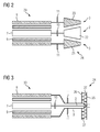
- the turbomachine strand 29 according to FIG. 2 and the turbomachine string 30 according to FIG. 3 differ from the turbomachinery 1 according to FIG. 1 to the effect that the two partial strands 2, 3 do not differ in different but extend in the same axial direction.
- the turbomachine strand 29 according to FIG. 2 has a twin-rotor flow machine 28, wherein the first sub-strand 2 has an inner rotor 22 and the second sub-strand 3 has an outer rotor 23 of the twin-rotor flow machine.
- the turbomachine strand 30 according to FIG. 3 includes a Ljungström turbine 24 having a first turbine half 25 and a second turbine half 26.
- the first sub-line 2 has the first turbine half 25 and the second sub-line 3 has the second turbine half 26.
- FIGS. 4 to 7 show a cross section through the turbomachine strand 1 in the region of the generator 6.
- the stator 9 and the outer rotor 8 are shown in the cross sections of the inner rotor 7, the stator 9 and the outer rotor 8 are shown.
- the rotor angle ⁇ inside is the angle between the magnetic field vector 16 of the inner rotor 7 and the magnetic field vector 18 of the mains magnetic field 21.
- the outer rotor angle ⁇ is the angle between the magnetic field vector 17 of the outer rotor 8 and the magnetic field vector 18 of the mains magnetic field 21.
- the magnetic field vectors 16, 17, 18 are directed in the direction from the south pole to the north pole. Also are in FIGS. 4 to 7 shown the rotational frequency ⁇ red, inside of the inner rotor 7, the rotational circle frequency ⁇ red, outside of the outer rotor 8 and angular frequency ⁇ network of the mains magnetic field 21, wherein the angular frequencies are each indicated by an arrow.
- the angular frequency ⁇ network indicates how fast the mains magnetic field 21 rotates.
- runners 7, 8 of the FIGS. 4 to 7 These are the runners of synchronous machines. In synchronous machines, the magnetic field 9, 20 of the respective rotor is fixed relative to the respective rotor, ie, the magnetic field of the respective rotor rotates at the same angular frequency as the rotor.
- the magnetic field vector 18 of the mains magnetic field 21 follows the respective magnetic field vector 16, 17.
- the magnetic field vector 18 of the mains magnetic field 21 precedes the respective magnetic field vector 16, 17.
- Figures 5 and 6 show the case that both runners 7, 8 are operated as a generator.
- FIG. 6 are the two Polradwinkel ⁇ inside and ⁇ outside different: ⁇ inside ⁇ 0, ⁇ outside ⁇ 0, ⁇ inside ⁇ ⁇ outside , whereby ⁇ inside ⁇ 0 and ⁇ outside > 0 would be.
- FIGS. 8 and 9 show a cross section through a turbomachine 12 in the region of the generator 6.
- the machine train 12 differs from the machine line 1 in that the inner rotor 13 is the rotor of an asynchronous machine.
- the external rotor 14 is the rotor of a synchronous machine.
- Also shown are the inner magnetic field 19 with the magnetic field vector 16 of the inner rotor 13, the outer magnetic field 20 with the magnetic field vector 17 of the outer rotor 14 and the mains magnetic field 21 with the magnetic field vector 18 of a mains magnetic field.
- the net magnetic field is the magnetic field generated by the stator 15.
- the Polradwinkel ⁇ inside is the angle between the magnetic field vector 16 of the inner rotor 7 and the magnetic field vector 18 of the net magnetic field 21.
- the pole wheel angle ⁇ outside is the angle between the magnetic field vector 17 of the external rotor 14 and the magnetic field vector 18 of the net magnetic field 21.
- the magnetic field vectors 16, 17, 18 are directed in the direction from the south pole to the north pole.
- FIGS. 8 and 9 represented the rotational circle frequency ⁇ red, outside of the external rotor 8 and the rotational circle frequency ⁇ network of the mains magnetic field 21.
- FIG. 8 is the rotational angular frequency of the inner rotor 13 ⁇ rot2 , inside .
- the inner magnetic field 19 of the inner rotor 13 rotates at a rotational angular frequency ⁇ Feld1 relative to the inner rotor 13.
- FIG. 9 is the rotational angular frequency of the inner rotor 13 ⁇ rot3, inside .
- the inner magnetic field 19 of the inner rotor 13 rotates at a rotational angular frequency ⁇ field 2 relative to the inner rotor 13.
- the inner rotor 13 rotates in the opposite direction to that of the outer rotor 14 and the inner magnetic field rotates in the same direction as the outer rotor 14.
Landscapes
- Engineering & Computer Science (AREA)
- Power Engineering (AREA)
- Mechanical Engineering (AREA)
- General Engineering & Computer Science (AREA)
- Connection Of Motors, Electrical Generators, Mechanical Devices, And The Like (AREA)
Priority Applications (1)
| Application Number | Priority Date | Filing Date | Title |
|---|---|---|---|
| EP15167166.6A EP3093452A1 (fr) | 2015-05-11 | 2015-05-11 | Train de turbomachines et procédé de fonctionnement d'un train de turbomachines |
Applications Claiming Priority (1)
| Application Number | Priority Date | Filing Date | Title |
|---|---|---|---|
| EP15167166.6A EP3093452A1 (fr) | 2015-05-11 | 2015-05-11 | Train de turbomachines et procédé de fonctionnement d'un train de turbomachines |
Publications (1)
| Publication Number | Publication Date |
|---|---|
| EP3093452A1 true EP3093452A1 (fr) | 2016-11-16 |
Family
ID=53177174
Family Applications (1)
| Application Number | Title | Priority Date | Filing Date |
|---|---|---|---|
| EP15167166.6A Withdrawn EP3093452A1 (fr) | 2015-05-11 | 2015-05-11 | Train de turbomachines et procédé de fonctionnement d'un train de turbomachines |
Country Status (1)
| Country | Link |
|---|---|
| EP (1) | EP3093452A1 (fr) |
Cited By (2)
| Publication number | Priority date | Publication date | Assignee | Title |
|---|---|---|---|---|
| CN107332429A (zh) * | 2017-07-20 | 2017-11-07 | 湖南大学 | 一种磁力耦合传动装置 |
| CN110748417A (zh) * | 2019-12-24 | 2020-02-04 | 沈阳微控新能源技术有限公司 | 一种基于磁耦合联轴器的涡轮增压器和发动机 |
Citations (4)
| Publication number | Priority date | Publication date | Assignee | Title |
|---|---|---|---|---|
| US3754174A (en) * | 1971-08-06 | 1973-08-21 | Kawasaki Heavy Ind Ltd | Exciting method of electric machine combining electromagnetic coupling with electric rotating machine |
| EP1931015A2 (fr) * | 2006-12-07 | 2008-06-11 | General Electric Company | Démarreur-générateur à double face pour avion |
| US8464511B1 (en) * | 2012-01-06 | 2013-06-18 | Hamilton Sundstrand Corporation | Magnetically coupled contra-rotating propulsion stages |
| US20130181562A1 (en) * | 2012-01-17 | 2013-07-18 | Hamilton Sundstrand Corporation | Dual-rotor machine |
-
2015
- 2015-05-11 EP EP15167166.6A patent/EP3093452A1/fr not_active Withdrawn
Patent Citations (4)
| Publication number | Priority date | Publication date | Assignee | Title |
|---|---|---|---|---|
| US3754174A (en) * | 1971-08-06 | 1973-08-21 | Kawasaki Heavy Ind Ltd | Exciting method of electric machine combining electromagnetic coupling with electric rotating machine |
| EP1931015A2 (fr) * | 2006-12-07 | 2008-06-11 | General Electric Company | Démarreur-générateur à double face pour avion |
| US8464511B1 (en) * | 2012-01-06 | 2013-06-18 | Hamilton Sundstrand Corporation | Magnetically coupled contra-rotating propulsion stages |
| US20130181562A1 (en) * | 2012-01-17 | 2013-07-18 | Hamilton Sundstrand Corporation | Dual-rotor machine |
Cited By (3)
| Publication number | Priority date | Publication date | Assignee | Title |
|---|---|---|---|---|
| CN107332429A (zh) * | 2017-07-20 | 2017-11-07 | 湖南大学 | 一种磁力耦合传动装置 |
| CN107332429B (zh) * | 2017-07-20 | 2019-09-03 | 湖南大学 | 一种磁力耦合传动装置 |
| CN110748417A (zh) * | 2019-12-24 | 2020-02-04 | 沈阳微控新能源技术有限公司 | 一种基于磁耦合联轴器的涡轮增压器和发动机 |
Similar Documents
| Publication | Publication Date | Title |
|---|---|---|
| DE3879013T2 (de) | Steuerbarer induktionsmotor mit veraenderbarer geschwindigkeit. | |
| DE102014003658B4 (de) | Reluktanzmotor | |
| EP1694944B1 (fr) | Turbine a gaz, notamment groupe motopropulseur | |
| DE102005060180A1 (de) | Elektrische Maschinen und Anordnungen mit einem jochlosen Stator mit modularen Blechstapeln | |
| WO2019020684A1 (fr) | Moteur électrique doté d'un dispositif de refroidissement | |
| DE102007059980A1 (de) | Elektrische Energieerzeugung unter Verwendung einer Arbeitsturbine hinter einer Niederdruckturbine | |
| EP2406869B1 (fr) | Rotor pour un turbogénérateur et turbogénérateur doté d'un rotor | |
| EP2930827B1 (fr) | Machine électrique à refroidissement par convection | |
| AT15009U1 (de) | Energiewandler | |
| DE102011112250A1 (de) | Hilfsgerätegetriebeeinrichtung für ein Triebwerk | |
| EP2993767A1 (fr) | Générateur pour une centrale | |
| DE102021101408A1 (de) | Elektrische maschine, antriebssystem und dessen verwendung | |
| WO2009024485A2 (fr) | Rotor d'un moteur de traction | |
| DE102007050496A1 (de) | Generator mit Multistator und Multirotor | |
| DE2007194A1 (de) | Kühlgasführung bei elektrischen Maschinen | |
| EP0045843B1 (fr) | Procédé pour l'utilisation de l'énergie de la chaleur perdue d'un moteur à combustion | |
| EP3093452A1 (fr) | Train de turbomachines et procédé de fonctionnement d'un train de turbomachines | |
| DE2842893A1 (de) | Waermepumpenheizungssystem | |
| WO2013166533A2 (fr) | Entraînement différentiel pour une installation de récupération d'énergie | |
| DE102014226861A1 (de) | Elektrischer Verdichter | |
| DE102022106633B4 (de) | Verbund aus einem elektrischen Netzwerk, einem Kraftwerk sowie einem Speicherkraftwerk sowie Verfahren zum Ausgleich einer fluktuierenden Leistungsbereitstellung des Kraftwerks | |
| DE102023106333A1 (de) | Elektrische Maschine, ausgebildet als eine Schenkelpol-Synchronmaschine, Komponente für eine als eine Schenkelpol-Synchronmaschine ausgebildete elektrische Maschine, Kraftfahrzeug umfassend eine elektrische Maschine und Verfahren zur Herstellung einer Komponente für eine als eine Schenkelpol-Synchronmaschine ausgebildete elektrische Maschine | |
| DE102023106328A1 (de) | Elektrische Maschine, Rotoranordnung für eine elektrische Maschine und Kraftfahrzeug mit einer elektrischen Maschine | |
| DE212014000175U1 (de) | Elektrische Turbomaschine und Energiewandler | |
| DE102008029377A1 (de) | Vorrichtung für eine Wind- oder Wasserkraftanlage zur Erzeugung elektrischer Energie |
Legal Events
| Date | Code | Title | Description |
|---|---|---|---|
| PUAI | Public reference made under article 153(3) epc to a published international application that has entered the european phase |
Free format text: ORIGINAL CODE: 0009012 |
|
| AK | Designated contracting states |
Kind code of ref document: A1 Designated state(s): AL AT BE BG CH CY CZ DE DK EE ES FI FR GB GR HR HU IE IS IT LI LT LU LV MC MK MT NL NO PL PT RO RS SE SI SK SM TR |
|
| AX | Request for extension of the european patent |
Extension state: BA ME |
|
| 17P | Request for examination filed |
Effective date: 20161104 |
|
| RBV | Designated contracting states (corrected) |
Designated state(s): AL AT BE BG CH CY CZ DE DK EE ES FI FR GB GR HR HU IE IS IT LI LT LU LV MC MK MT NL NO PL PT RO RS SE SI SK SM TR |
|
| RAP1 | Party data changed (applicant data changed or rights of an application transferred) |
Owner name: SIEMENS AKTIENGESELLSCHAFT |
|
| 17Q | First examination report despatched |
Effective date: 20190226 |
|
| STAA | Information on the status of an ep patent application or granted ep patent |
Free format text: STATUS: THE APPLICATION IS DEEMED TO BE WITHDRAWN |
|
| 18D | Application deemed to be withdrawn |
Effective date: 20190709 |