EP3093518B2 - Unité de réglage pour un régleur automatique de timonerie - Google Patents
Unité de réglage pour un régleur automatique de timonerie Download PDFInfo
- Publication number
- EP3093518B2 EP3093518B2 EP15001411.6A EP15001411A EP3093518B2 EP 3093518 B2 EP3093518 B2 EP 3093518B2 EP 15001411 A EP15001411 A EP 15001411A EP 3093518 B2 EP3093518 B2 EP 3093518B2
- Authority
- EP
- European Patent Office
- Prior art keywords
- worm
- adjusting unit
- worm shaft
- shaft
- stop
- Prior art date
- Legal status (The legal status is an assumption and is not a legal conclusion. Google has not performed a legal analysis and makes no representation as to the accuracy of the status listed.)
- Active
Links
Images

Classifications
-
- F—MECHANICAL ENGINEERING; LIGHTING; HEATING; WEAPONS; BLASTING
- F16—ENGINEERING ELEMENTS AND UNITS; GENERAL MEASURES FOR PRODUCING AND MAINTAINING EFFECTIVE FUNCTIONING OF MACHINES OR INSTALLATIONS; THERMAL INSULATION IN GENERAL
- F16D—COUPLINGS FOR TRANSMITTING ROTATION; CLUTCHES; BRAKES
- F16D65/00—Parts or details
- F16D65/38—Slack adjusters
- F16D65/40—Slack adjusters mechanical
- F16D65/62—Slack adjusters mechanical self-acting in both directions for adjusting excessive and insufficient play
- F16D65/68—Slack adjusters mechanical self-acting in both directions for adjusting excessive and insufficient play with eccentric or helical body
-
- F—MECHANICAL ENGINEERING; LIGHTING; HEATING; WEAPONS; BLASTING
- F16—ENGINEERING ELEMENTS AND UNITS; GENERAL MEASURES FOR PRODUCING AND MAINTAINING EFFECTIVE FUNCTIONING OF MACHINES OR INSTALLATIONS; THERMAL INSULATION IN GENERAL
- F16D—COUPLINGS FOR TRANSMITTING ROTATION; CLUTCHES; BRAKES
- F16D65/00—Parts or details
- F16D65/38—Slack adjusters
- F16D65/40—Slack adjusters mechanical
- F16D65/42—Slack adjusters mechanical non-automatic
- F16D65/48—Slack adjusters mechanical non-automatic with eccentric or helical body
-
- F—MECHANICAL ENGINEERING; LIGHTING; HEATING; WEAPONS; BLASTING
- F16—ENGINEERING ELEMENTS AND UNITS; GENERAL MEASURES FOR PRODUCING AND MAINTAINING EFFECTIVE FUNCTIONING OF MACHINES OR INSTALLATIONS; THERMAL INSULATION IN GENERAL
- F16D—COUPLINGS FOR TRANSMITTING ROTATION; CLUTCHES; BRAKES
- F16D65/00—Parts or details
- F16D65/38—Slack adjusters
- F16D65/40—Slack adjusters mechanical
- F16D65/52—Slack adjusters mechanical self-acting in one direction for adjusting excessive play
- F16D65/60—Slack adjusters mechanical self-acting in one direction for adjusting excessive play for angular adjustment of two concentric parts of the brake control systems
-
- F—MECHANICAL ENGINEERING; LIGHTING; HEATING; WEAPONS; BLASTING
- F16—ENGINEERING ELEMENTS AND UNITS; GENERAL MEASURES FOR PRODUCING AND MAINTAINING EFFECTIVE FUNCTIONING OF MACHINES OR INSTALLATIONS; THERMAL INSULATION IN GENERAL
- F16D—COUPLINGS FOR TRANSMITTING ROTATION; CLUTCHES; BRAKES
- F16D51/00—Brakes with outwardly-movable braking members co-operating with the inner surface of a drum or the like
Definitions
- the present invention relates to an adjustment unit for an automatic slack adjuster of a brake, in particular a commercial vehicle drum brake, the adjustment unit having: a housing, a worm shaft, which is mounted in the housing so that it can be displaced between two end positions by an axial stroke, a control pinion arranged on the worm shaft, a a worm arranged on the worm shaft, and a one-way clutch arranged to transmit power between the control pinion and the worm in a first direction of rotation and to slip between the control pinion and the worm in an opposite second direction of rotation.
- Automatic slack adjusters with adjustment mechanisms are known, for example, from EP01917451B1 , EP 02307757 A1 , EP02352931B1 , EP 0598290 A1 , EP 0598290 B1 , U.S. 7,757,824 B2 , US 8,215,460 B2 , U.S. 8,245,820 B2 , WO 02003/083322 A1 .
- Automatic slack adjusters are known throughout the industry in connection with drum brakes as so-called “automatic slack adjusters” and are used to regulate the clearance between the brake lining and the brake drum.
- Automatic adjustment units for slack adjusters have the function of preventing the clearance between the brake pad and drum brake from becoming too small or too large. If the gap between the brake pad and the brake drum is too small, the brake pad wear will increase, and so-called “overheating” can also occur in extreme situations. On the other hand, if the air gap between the brake lining and the brake drum is too large, the braking force will not be sufficient the braking system is transferred. Thus, the variation in clearance has a direct impact on the braking performance of the drum brake.
- drum brakes are usually used on commercial vehicles, for example a drum brake is arranged on each wheel, it is essential for safe operation of the vehicle that the clearance varies as little as possible across the different drum brakes. For example, if the clearance on the right side of an axle on the brake provided there was significantly smaller than on the opposite left side, the braking effect would be different and the vehicle would pull to the right when braking. In addition to the braking effect itself, the clearance also has an influence on the vehicle set-up.
- the invention was based on the object of specifying an adjustment unit for an automatic slack adjuster which alleviates the disadvantages found as far as possible.
- the invention was based on the object of improving an adjustment unit of the type described at the outset in such a way that the clearance of the slack adjuster fluctuates less.
- the invention was based in particular on the additional object of improving the adjustment unit described at the outset to the effect that assembly is simplified.
- the invention solves the task on which it is based in an adjustment unit of the type described at the beginning with the features of claim 1.
- the adjustment unit is characterized in that the worm shaft has a first and a second stop surface, which each have a corresponding stop at the end positions of the Housing can be brought into contact.
- the axial stroke in particular defines the clearance of the slack adjuster. The invention thus follows the approach that the axial stroke of the adjustment unit should fluctuate as little as possible. The invention takes up this in that the two end positions are defined on the shaft side by the first and second stop surface on the worm shaft itself.
- the control pinion is preferably set up to engage in a control disc of the automatic slack adjuster, in particular one that is non-rotatably connected to a control arm.
- the control arm is preferably part of the slack adjuster.
- the worm is preferably adapted to engage in a worm wheel of a drive shaft, the worm wheel being rotated by the worm when the worm shaft is in one of the two end positions in the housing.
- the worm wheel is preferably operatively connected to the drive shaft by means of a clutch, the drive shaft being operatively connected to a mechanism for moving the brake pads.
- Such a movement mechanism is known, for example, under the term "S-cam”.
- the freewheel is preferably arranged to act between the control pinion and the worm shaft, or between the control pinion and the worm directly, or between the worm shaft and the worm.
- the worm wheel in which the worm of the adjustment unit engages, is preferably coupled by means of a clutch to a drive shaft, which in turn is set up to drive the movement mechanism for adjusting the brake pads.
- the worm is arranged non-rotatably on the worm shaft in that it is formed in one piece with the worm shaft and in that the control pinion is coupled to the worm shaft by means of the freewheel. Due to the fact that the worm is arranged on the worm shaft in a rotationally fixed manner and is formed in one piece with the worm shaft, the ease of assembly of the adjustment unit is improved overall. In terms of assembly, this makes it possible for the control pinion to be plugged onto the component consisting of the worm and the shaft. At the same time, the stop surfaces of the worm shaft still define the dimensional accuracy with regard to the clearance, so that the axial dimensions of the control pinion are not important, and the latter can be manufactured much more cheaply.
- the adjustment unit is preferably further developed in that it has an axial spring which is operatively connected to the housing and the worm shaft and is set up to move the worm shaft in the direction of the second to pretension the stop. By means of the preload in the direction of the second stop, the design-related clearance is maintained and a normal position of the worm shaft is defined.
- the first stop surface is designed as the shaft end of the worm shaft. More preferably, the second stop surface is designed as a shaft shoulder.
- the worm shaft particularly preferably has a sliding bearing section that is loosely mounted in the housing adjacent to the second stop face.
- the latter measure is particularly advantageous when the worm is designed to be connected to the worm shaft in one piece.
- the sliding bearing section is made of a hardened metallic material.
- the worm and the control pinion are arranged in the axial direction between the first and second stop surfaces.
- the freewheel is preferably designed as a wrap spring, roller freewheel, helical gearing with preload, pawl or combinations of the above.
- the axial spring is preferably designed as: helical spring, plate spring, wave spring, or as a combination of the above.
- control pinion is slipped onto the worm shaft and has a recess for receiving the axial spring, preferably on one of the first stop faces facing Page. Because the axial spring dips into the control pinion on the side facing the first stop, the axial spring presses the control pinion onto the worm shaft, but without having to accept an influence of the control pinion on the dimensional accuracy. This is still defined by the first and second stop surfaces on the worm shaft itself. In the normal state, the axial spring preferably pushes the first stop surface away from its end position there and has the effect that instead the second stop surface is in contact with the housing at the corresponding opposite end position.
- This advantageous arrangement of the axial spring means that a large number of other fastening and guiding means, such as screw connections, guides or the like, can thus be dispensed with.
- the total number of components required is significantly lower than is sometimes known from the prior art, which further simplifies assembly.
- the invention relates to an automatic slack adjuster for a drum brake, in particular a commercial vehicle drum brake.
- the automatic slack adjuster has an adjustment unit according to one of the preferred embodiments described herein.
- the automatic slack adjuster has the same preferred embodiments as the adjustment unit according to the invention.
- the invention relates to a vehicle, in particular a commercial vehicle, with a number of wheels, one, several or all of the wheels being braked by means of a drum brake, one, several or all of the drum brakes each being assigned an automatic slack adjuster with an adjustment unit is.
- this is an adjustment unit according to one of the preferred embodiments described herein, or is an automatic slack adjuster according to one of the preferred embodiments described herein.
- the Figures 1a,b show an adjustment unit 1 according to a preferred exemplary embodiment in an optional form, ie without a housing environment.
- the adjustment unit 1 has a worm shaft 2 which has a first stop surface 3 and a second stop surface 5 .
- the first stop surface 3 is designed as a shaft end, while the second stop surface 5 is designed as a shaft shoulder.
- a sliding bearing section 6 is formed on the worm shaft 2 at an end opposite the first stop surface 3 and is designed to be inserted into a corresponding guide bore of a housing ( figure 2 ).
- the worm shaft 2 has a worm 7 which, according to the invention, is arranged in one piece on the worm shaft 2 .
- the adjustment unit 1 also has a freewheel 13, which in the present case is designed as a wrap spring.
- the freewheel 13 and a control pinion 9 can be plugged onto the worm shaft 2, the freewheel 13 being pushed onto a shaft shoulder 15 and being set up to bring about a force or torque transmission between the control pinion 9 and the worm 7 in a first direction of rotation. while the freewheel 13 provides slippage between these two components 9, 7 in the opposite second direction of rotation.
- the adjustment unit 1 also has an axial spring 11 which is accommodated in a recess 17 in the control pinion 9 .
- the axial spring 11 is set up to press the freewheel 13 and the control pinion 9 in the direction of the second stop face 5 and thus to hold them on the worm shaft 2 .
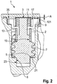
- the adjustment unit 1 is shown in the installed position within the housing 19 (indicated by the dashed box).
- the worm shaft 2 is inserted with its slide bearing section 6 into a corresponding guide recess 23 .
- the second stop surface 5 is in contact with a corresponding second stop 21 in the housing 19.
- the first stop surface 3 is spaced from a corresponding first stop 25 of the housing 19 by an axial stroke A.
- the axial stroke A defines the clearance of the drum brake, as below with reference to figure 4 will be explained later.
- the control pinion 9 engages in a control disk 101 .
- the worm shaft 2 has a distance between the first and second stop surface 3.5 that allows both the worm 7 and the control pinion 9 to lie between these two stop surfaces, so that the axial stroke A is composed of a single tolerance .
- the axial stroke A will preferably be on the order of a few tenths of a millimeter.
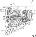
- the adjustment unit 1 is shown in its structural and functional interaction with other components of a slack adjuster 100.
- the slack adjuster 100 has a control arm 102 which is firmly connected to the control disc 101 .
- the slack adjuster 100 also has a drive wheel 103, which is set up by means of an inner profile 105 to control a movement mechanism for actuating the brake pads in a drum brake.
- a sealing ring 107 can be used to seal this driven section against a surrounding housing.
- the drive wheel 103 is in engagement with a drive worm 109 of a drive shaft 111.
- the drive shaft 111 is rotatably supported in the housing 19 .
- a compression spring 113 (shown in Fig figure 4 ) arranged to act against a spring seat 115 and covered by a spring cover 119 and a corresponding sealing ring 121.
- the drive shaft 111 also has an adjustment toothing 123 which is in engagement with the worm 7 of the adjustment unit 1 .
- a bearing 125 is arranged at the top right-hand side, by means of which the drive shaft 111 is rotatably accommodated in the housing 19 .
- the drive shaft 111 has a claw clutch 131 which is set up to prevent a power transmission between the adjustment device 123 and the drive worm 109 when a predefined force is exceeded by overcoming the compression spring 113 and to disengage the claw clutch 131 .
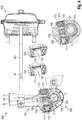
- a brake 200 is actuated in a vehicle 300, the applied braking force is transmitted by means of a connecting rod 201 in the direction of arrow B to the housing 19 of the slack adjuster, which is then set in a pivoting movement about the axis of rotation C.
- the drive wheel 103 is rotated counterclockwise because it is carried along by the drive worm 109 of the drive shaft 111 in the axial direction thereof.
- the control pinion 9 also rolls on the control disc 101 as a result of the pivoting movement.
- the housing 19 With continued movement of the connecting rod in the direction of arrow B, the housing 19 first passes through a pivoting range H, which represents the nominal stroke, before it passes through a range H U , which represents an excessive stroke due to progressive wear of the brake pads.
- a pivoting range H which represents the nominal stroke
- a range H U which represents an excessive stroke due to progressive wear of the brake pads.
- the worm shaft 2 is initially deflected in its axial direction until, overcoming the force of the axial spring 11, it has been brought into the end position there, in which the first stop surface 3 comes into contact with the corresponding first stop 25 of the housing 19 stands. Only after this axial play has been overcome does the drive shaft 111 rotate and can the drive worm 109 deflect the drive wheel 103 . This process is the actual adjustment process.
- the axial stroke A defines the amount of play with regard to the transmission of a rotational movement to the drive wheel 103, in which at least one relaxation movement of the brake linings takes place before the adjustment becomes active. The less the axial stroke A varies during operation, the more reliably the adjustment unit 1 consequently keeps the clearance constant.
Landscapes
- Engineering & Computer Science (AREA)
- General Engineering & Computer Science (AREA)
- Mechanical Engineering (AREA)
- Braking Arrangements (AREA)
Claims (12)
- Unité de réglage (1) pour un régleur automatique de timonerie (100) d'un frein (200), en particulier d'un frein à tambour de véhicule utilitaire, l'unité de réglage présentant :- un carter (19),- un arbre de vis sans fin (2) monté dans le carter (19) de façon déplaçable de l'ordre d'une course axiale A entre deux positions d'extrémité,- un pignon de commande (9) disposé sur l'arbre de vis sans fin,- une vis sans fin (7) disposée sur l'arbre de vis sans fin, et- une roue libre (13) qui est étudiée pour la transmission de force entre le pignon de commande (9) et la vis sans fin (7) dans un premier sens de rotation et pour le glissement entre le pignon de commande (9) et la vis sans fin (7) dans un deuxième sens de rotation contraire,caractérisée en ce que l'arbre de vis sans fin présente une première et une deuxième surface de butée (3, 5), lesquelles peuvent être respectivement mises en contact avec une première butée (25) et une deuxième butée (21) correspondantes au niveau des positions d'extrémité du carter (19), la vis sans fin (7) étant réalisée d'une seule pièce avec l'arbre de vis sans fin (2), le pignon de commande (9) étant couplé au moyen de la roue libre (13) avec l'arbre de vis sans fin (2), et la course axiale A définissant le jeu d'aération du régleur de timonerie (100).
- Unité de réglage (1) selon la revendication 1,
avec un ressort axial (11) qui est en liaison active avec le carter (19) et l'arbre de vis sans fin (2) et est étudié pour précontraindre l'arbre de vis sans fin (2) en direction de la deuxième butée (21). - Unité de réglage (1) selon l'une quelconque des revendications précédentes,
dans laquelle la première surface de butée (3) est réalisée en tant que bout d'arbre. - Unité de réglage (1) selon l'une quelconque des revendications précédentes,
dans laquelle la deuxième surface de butée (5) est réalisée en tant que talon d'arbre. - Unité de réglage (1) selon l'une quelconque des revendications précédentes,
dans laquelle l'arbre de vis sans fin (2) présente, au voisinage de la deuxième surface de butée (5), une partie de palier lisse (6) librement logée dans le carter (19). - Unité de réglage (1) selon la revendication 5,
dans laquelle la partie de palier lisse (6) est réalisée en un matériau métallique durci. - Unité de réglage (1) selon l'une quelconque des revendications précédentes,
dans laquelle la vis sans fin (7) et le pignon de commande (9) sont disposés en direction axiale entre la première et la deuxième surface de butée (3, 5). - Unité de réglage (1) selon l'une quelconque des revendications précédentes,
dans laquelle la roue libre (13) est réalisée en tant que : ressort enroulé, roue libre à rouleaux, denture hélicoïdale avec précontrainte, cliquet d'arrêt, ou en tant que combinaison de ce qui précède. - Unité de réglage (1) selon l'une quelconque des revendications 2 à 8,
dans laquelle le ressort axial (11) est réalisé en tant que : ressort à boudin, rondelle de Belleville, ressort sinueux, ou en tant que combinaison de ce qui précède. - Unité de réglage (1) selon l'une quelconque des revendications précédentes,
dans laquelle le pignon de commande (9) est monté sur l'arbre de vis sans fin (2) et présente un évidement (17) pour la réception du ressort axial (11), de préférence sur un côté tourné vers la première surface de butée (3). - Régleur automatique de timonerie (100) pour un frein, en particulier un frein à tambour de véhicule utilitaire,
avec une unité de réglage (1) selon l'une quelconque des revendications précédentes. - Véhicule (300), en particulier véhicule utilitaire, avec
un certain nombre de roues, dans lequel l'une, plusieurs, ou l'ensemble des roues sont freinées au moyen d'un frein à tambour (200), dans lequel on associe à un, plusieurs, ou l'ensemble des freins à tambour respectivement un régleur automatique de timonerie (100) avec une unité de réglage (1) selon l'une des revendications 1 à 10.
Priority Applications (3)
| Application Number | Priority Date | Filing Date | Title |
|---|---|---|---|
| EP15001411.6A EP3093518B2 (fr) | 2015-05-11 | 2015-05-11 | Unité de réglage pour un régleur automatique de timonerie |
| US15/145,146 US10107345B2 (en) | 2015-05-11 | 2016-05-03 | Adjusting unit for an automatic slack adjuster |
| CN201610304109.3A CN106151328B (zh) | 2015-05-11 | 2016-05-10 | 用于自动调整臂的调校单元 |
Applications Claiming Priority (1)
| Application Number | Priority Date | Filing Date | Title |
|---|---|---|---|
| EP15001411.6A EP3093518B2 (fr) | 2015-05-11 | 2015-05-11 | Unité de réglage pour un régleur automatique de timonerie |
Publications (3)
| Publication Number | Publication Date |
|---|---|
| EP3093518A1 EP3093518A1 (fr) | 2016-11-16 |
| EP3093518B1 EP3093518B1 (fr) | 2018-08-29 |
| EP3093518B2 true EP3093518B2 (fr) | 2022-01-12 |
Family
ID=53058961
Family Applications (1)
| Application Number | Title | Priority Date | Filing Date |
|---|---|---|---|
| EP15001411.6A Active EP3093518B2 (fr) | 2015-05-11 | 2015-05-11 | Unité de réglage pour un régleur automatique de timonerie |
Country Status (3)
| Country | Link |
|---|---|
| US (1) | US10107345B2 (fr) |
| EP (1) | EP3093518B2 (fr) |
| CN (1) | CN106151328B (fr) |
Families Citing this family (5)
| Publication number | Priority date | Publication date | Assignee | Title |
|---|---|---|---|---|
| CN109563896A (zh) * | 2017-05-31 | 2019-04-02 | 马德拉斯工程工业私人有限公司 | 自动间隙调整器 |
| US10704630B2 (en) | 2018-05-14 | 2020-07-07 | Bendix Spicer Foundation Brake Llc | Automatic slack adjuster with adjusting clutch in control train |
| US11209062B2 (en) * | 2019-05-15 | 2021-12-28 | Bendix Commercial Vehicle Systems Llc | Automatic slack adjuster |
| DE102019005094B3 (de) * | 2019-07-23 | 2020-09-03 | Haldex Brake Products Ab | Nachstelleinheit für eine Bremse und Herstellungsverfahren hierfür |
| EP3985447A1 (fr) * | 2020-10-19 | 2022-04-20 | Glashütter Uhrenbetrieb GmbH | Levier réglable d'un mécanisme de tourbillon et procédé de réglage |
Family Cites Families (17)
| Publication number | Priority date | Publication date | Assignee | Title |
|---|---|---|---|---|
| GB1085048A (en) * | 1966-05-27 | 1967-09-27 | Bromsregulator Svenska Ab | Improvements in automatic slack adjusters for vehicle brake linkages |
| US4380276A (en) * | 1980-07-21 | 1983-04-19 | Kelsey-Hayes Co. | Slack adjuster for vehicle brakes |
| DE4017949A1 (de) * | 1990-06-05 | 1991-12-12 | Wabco Westinghouse Fahrzeug | Einrichtung zum selbsttaetigen nachstellen einer bremse, insbesondere fahrzeugbremse |
| SE470526B (sv) | 1992-11-18 | 1994-07-04 | Haldex Ab | Bromshävarm för en s-kambroms hos ett landsvägsfordon |
| EP0762007A1 (fr) * | 1995-08-17 | 1997-03-12 | Grau Limited | Dispositif de rajustage pour frein de véhicule |
| SE512102C2 (sv) * | 1998-03-27 | 2000-01-24 | Haldex Brake Prod Ab | Reglerarrangemang för en bromshävarm |
| WO2003083322A1 (fr) | 2002-04-01 | 2003-10-09 | Madras Engineering Industries Limited | Dispositif de reglage automatique des freins pour le rattrapage de jeu entre la garniture de frein et le tambour de frein dans un systeme de freinage de vehicule automobile |
| CN2612835Y (zh) * | 2003-04-11 | 2004-04-21 | 赵必清 | 带制动衬片磨损报警装置的汽车制动间隙自动调整器 |
| JP3881966B2 (ja) * | 2003-04-25 | 2007-02-14 | 本田技研工業株式会社 | ディスクブレーキ装置の間隙調整装置 |
| ES2611013T3 (es) * | 2004-04-07 | 2017-05-04 | Madras Engineering Industries Private Ltd. | Regulador de holgura automático para un freno de tambor de un vehículo |
| KR101121125B1 (ko) | 2005-08-25 | 2012-03-19 | 마드라스 엔지니어링 인더스트리스 프라이빗 리미티드 | 운송수단 브레이킹 시스템의 브레이크 라이닝 및 브레이크드럼 사이의 슬랙을 조정하는 자동 브레이크 조정기 |
| RU2398986C2 (ru) * | 2005-11-14 | 2010-09-10 | Общество С Дополнительной Ответственностью "Дискомс" | Регулятор тормоза транспортного средства |
| TR200805758A2 (tr) | 2008-08-05 | 2009-04-21 | Aydinsan Fi̇ren Circirlari Ve Otomoti̇v Yedek Parçalari İmalati Pazarlama Ve Satişi Sanayi̇ Ve Ti̇caret Li̇mi̇ted Şi̇rketi̇ | Fonksi̇yonel tam otomati̇k fren boşluk ayarlayici |
| US8672101B2 (en) * | 2008-11-18 | 2014-03-18 | Bendix Spicer Foundation Brake Llc | Automatic slack adjuster with clutch release cam |
| CN101526116B (zh) | 2009-03-24 | 2012-03-07 | 隆中控股集团有限公司 | 一种汽车自动调整臂 |
| DE202011106746U1 (de) * | 2011-10-14 | 2011-12-05 | Haldex Brake Products Ab | Bremshebel für eine Trommelbremse |
| CN202510597U (zh) * | 2012-03-24 | 2012-10-31 | 三一重工股份有限公司 | 制动间隙调整臂及具有其的车辆 |
-
2015
- 2015-05-11 EP EP15001411.6A patent/EP3093518B2/fr active Active
-
2016
- 2016-05-03 US US15/145,146 patent/US10107345B2/en active Active
- 2016-05-10 CN CN201610304109.3A patent/CN106151328B/zh active Active
Also Published As
| Publication number | Publication date |
|---|---|
| US10107345B2 (en) | 2018-10-23 |
| US20160333952A1 (en) | 2016-11-17 |
| CN106151328B (zh) | 2020-04-17 |
| CN106151328A (zh) | 2016-11-23 |
| EP3093518B1 (fr) | 2018-08-29 |
| EP3093518A1 (fr) | 2016-11-16 |
Similar Documents
| Publication | Publication Date | Title |
|---|---|---|
| EP2222977B1 (fr) | Frein à friction électromécanique | |
| EP3102845B1 (fr) | Frein à disque de véhicule | |
| DE102010045791B4 (de) | Reibungskupplung mit weggesteuerter Verschleißkompensation | |
| DE202011106746U1 (de) | Bremshebel für eine Trommelbremse | |
| EP3093518B1 (fr) | Unité de réglage pour un régleur automatique de timonerie | |
| EP3183465B1 (fr) | Dispositif de rattrapage d'un frein à disque et frein à disque équipé d'un tel dispositif de rattrapage | |
| DE102009007828B4 (de) | Reibungskupplung | |
| WO2012072394A1 (fr) | Actionneur | |
| EP3320222B1 (fr) | Dispositif de rattrapage pour frein à disque | |
| DE102005041342B4 (de) | Gestängesteller für Trommelbremse | |
| WO2019052636A1 (fr) | Embrayage à roue libre présentant une force de réglage induite par frottement | |
| DE102017119079A1 (de) | Doppelschlingfeder, Rotationseinrichtung und zu aktuierendes System | |
| EP1388681B1 (fr) | Ensemble plateau de pression muni d'un rattrapage de jeu automatique | |
| DE102005005250B4 (de) | Nachstellvorrichtung für pneumatisch betätigte Scheibenbremsen und Scheibenbremse | |
| EP3867544B1 (fr) | Frein à disque | |
| EP1886045B1 (fr) | Regleur de timonerie destine a un frein a tambour | |
| WO2018060221A1 (fr) | Mécanisme de commande muni d'une double roue dentée à roue libre en deux parties pour la protection mécanique de la transmission, et boîtier du mécanisme de commande | |
| DE102012213658A1 (de) | Kupplungsvorrichtung | |
| DE102019118319A1 (de) | Nachstelleinheit für ein axial betätigbares Kupplungssystem, Betätigungsvorrichtung sowie Verfahren zum Betrieb einer Betätigungsvorrichtung | |
| DE2629211A1 (de) | Hydraulische scheibenbremse | |
| EP1475550B1 (fr) | Embrayage à friction | |
| DE102023118012A1 (de) | Abnutzungsausgleichsdistanzstück | |
| EP1819937B1 (fr) | Frein a disque a commande pneumatique ou electromecanique | |
| WO2018233754A1 (fr) | Dispositif de transmission de couple | |
| DE102016204109A1 (de) | Reibungskupplung |
Legal Events
| Date | Code | Title | Description |
|---|---|---|---|
| PUAI | Public reference made under article 153(3) epc to a published international application that has entered the european phase |
Free format text: ORIGINAL CODE: 0009012 |
|
| AK | Designated contracting states |
Kind code of ref document: A1 Designated state(s): AL AT BE BG CH CY CZ DE DK EE ES FI FR GB GR HR HU IE IS IT LI LT LU LV MC MK MT NL NO PL PT RO RS SE SI SK SM TR |
|
| AX | Request for extension of the european patent |
Extension state: BA ME |
|
| STAA | Information on the status of an ep patent application or granted ep patent |
Free format text: STATUS: REQUEST FOR EXAMINATION WAS MADE |
|
| 17P | Request for examination filed |
Effective date: 20170516 |
|
| RBV | Designated contracting states (corrected) |
Designated state(s): AL AT BE BG CH CY CZ DE DK EE ES FI FR GB GR HR HU IE IS IT LI LT LU LV MC MK MT NL NO PL PT RO RS SE SI SK SM TR |
|
| GRAP | Despatch of communication of intention to grant a patent |
Free format text: ORIGINAL CODE: EPIDOSNIGR1 |
|
| STAA | Information on the status of an ep patent application or granted ep patent |
Free format text: STATUS: GRANT OF PATENT IS INTENDED |
|
| RIC1 | Information provided on ipc code assigned before grant |
Ipc: F16D 65/60 20060101AFI20170920BHEP |
|
| INTG | Intention to grant announced |
Effective date: 20171017 |
|
| GRAS | Grant fee paid |
Free format text: ORIGINAL CODE: EPIDOSNIGR3 |
|
| GRAA | (expected) grant |
Free format text: ORIGINAL CODE: 0009210 |
|
| STAA | Information on the status of an ep patent application or granted ep patent |
Free format text: STATUS: THE PATENT HAS BEEN GRANTED |
|
| AK | Designated contracting states |
Kind code of ref document: B1 Designated state(s): AL AT BE BG CH CY CZ DE DK EE ES FI FR GB GR HR HU IE IS IT LI LT LU LV MC MK MT NL NO PL PT RO RS SE SI SK SM TR |
|
| REG | Reference to a national code |
Ref country code: GB Ref legal event code: FG4D Free format text: NOT ENGLISH |
|
| REG | Reference to a national code |
Ref country code: CH Ref legal event code: EP |
|
| REG | Reference to a national code |
Ref country code: AT Ref legal event code: REF Ref document number: 1035489 Country of ref document: AT Kind code of ref document: T Effective date: 20180915 |
|
| REG | Reference to a national code |
Ref country code: IE Ref legal event code: FG4D Free format text: LANGUAGE OF EP DOCUMENT: GERMAN |
|
| REG | Reference to a national code |
Ref country code: DE Ref legal event code: R096 Ref document number: 502015005614 Country of ref document: DE |
|
| REG | Reference to a national code |
Ref country code: SE Ref legal event code: TRGR |
|
| REG | Reference to a national code |
Ref country code: NL Ref legal event code: MP Effective date: 20180829 |
|
| REG | Reference to a national code |
Ref country code: LT Ref legal event code: MG4D |
|
| PG25 | Lapsed in a contracting state [announced via postgrant information from national office to epo] |
Ref country code: FI Free format text: LAPSE BECAUSE OF FAILURE TO SUBMIT A TRANSLATION OF THE DESCRIPTION OR TO PAY THE FEE WITHIN THE PRESCRIBED TIME-LIMIT Effective date: 20180829 Ref country code: NL Free format text: LAPSE BECAUSE OF FAILURE TO SUBMIT A TRANSLATION OF THE DESCRIPTION OR TO PAY THE FEE WITHIN THE PRESCRIBED TIME-LIMIT Effective date: 20180829 Ref country code: BG Free format text: LAPSE BECAUSE OF FAILURE TO SUBMIT A TRANSLATION OF THE DESCRIPTION OR TO PAY THE FEE WITHIN THE PRESCRIBED TIME-LIMIT Effective date: 20181129 Ref country code: IS Free format text: LAPSE BECAUSE OF FAILURE TO SUBMIT A TRANSLATION OF THE DESCRIPTION OR TO PAY THE FEE WITHIN THE PRESCRIBED TIME-LIMIT Effective date: 20181229 Ref country code: NO Free format text: LAPSE BECAUSE OF FAILURE TO SUBMIT A TRANSLATION OF THE DESCRIPTION OR TO PAY THE FEE WITHIN THE PRESCRIBED TIME-LIMIT Effective date: 20181129 Ref country code: LT Free format text: LAPSE BECAUSE OF FAILURE TO SUBMIT A TRANSLATION OF THE DESCRIPTION OR TO PAY THE FEE WITHIN THE PRESCRIBED TIME-LIMIT Effective date: 20180829 Ref country code: RS Free format text: LAPSE BECAUSE OF FAILURE TO SUBMIT A TRANSLATION OF THE DESCRIPTION OR TO PAY THE FEE WITHIN THE PRESCRIBED TIME-LIMIT Effective date: 20180829 Ref country code: GR Free format text: LAPSE BECAUSE OF FAILURE TO SUBMIT A TRANSLATION OF THE DESCRIPTION OR TO PAY THE FEE WITHIN THE PRESCRIBED TIME-LIMIT Effective date: 20181130 |
|
| PG25 | Lapsed in a contracting state [announced via postgrant information from national office to epo] |
Ref country code: HR Free format text: LAPSE BECAUSE OF FAILURE TO SUBMIT A TRANSLATION OF THE DESCRIPTION OR TO PAY THE FEE WITHIN THE PRESCRIBED TIME-LIMIT Effective date: 20180829 Ref country code: LV Free format text: LAPSE BECAUSE OF FAILURE TO SUBMIT A TRANSLATION OF THE DESCRIPTION OR TO PAY THE FEE WITHIN THE PRESCRIBED TIME-LIMIT Effective date: 20180829 Ref country code: AL Free format text: LAPSE BECAUSE OF FAILURE TO SUBMIT A TRANSLATION OF THE DESCRIPTION OR TO PAY THE FEE WITHIN THE PRESCRIBED TIME-LIMIT Effective date: 20180829 |
|
| PG25 | Lapsed in a contracting state [announced via postgrant information from national office to epo] |
Ref country code: ES Free format text: LAPSE BECAUSE OF FAILURE TO SUBMIT A TRANSLATION OF THE DESCRIPTION OR TO PAY THE FEE WITHIN THE PRESCRIBED TIME-LIMIT Effective date: 20180829 Ref country code: EE Free format text: LAPSE BECAUSE OF FAILURE TO SUBMIT A TRANSLATION OF THE DESCRIPTION OR TO PAY THE FEE WITHIN THE PRESCRIBED TIME-LIMIT Effective date: 20180829 Ref country code: CZ Free format text: LAPSE BECAUSE OF FAILURE TO SUBMIT A TRANSLATION OF THE DESCRIPTION OR TO PAY THE FEE WITHIN THE PRESCRIBED TIME-LIMIT Effective date: 20180829 Ref country code: RO Free format text: LAPSE BECAUSE OF FAILURE TO SUBMIT A TRANSLATION OF THE DESCRIPTION OR TO PAY THE FEE WITHIN THE PRESCRIBED TIME-LIMIT Effective date: 20180829 Ref country code: IT Free format text: LAPSE BECAUSE OF FAILURE TO SUBMIT A TRANSLATION OF THE DESCRIPTION OR TO PAY THE FEE WITHIN THE PRESCRIBED TIME-LIMIT Effective date: 20180829 Ref country code: PL Free format text: LAPSE BECAUSE OF FAILURE TO SUBMIT A TRANSLATION OF THE DESCRIPTION OR TO PAY THE FEE WITHIN THE PRESCRIBED TIME-LIMIT Effective date: 20180829 |
|
| REG | Reference to a national code |
Ref country code: DE Ref legal event code: R026 Ref document number: 502015005614 Country of ref document: DE |
|
| PG25 | Lapsed in a contracting state [announced via postgrant information from national office to epo] |
Ref country code: DK Free format text: LAPSE BECAUSE OF FAILURE TO SUBMIT A TRANSLATION OF THE DESCRIPTION OR TO PAY THE FEE WITHIN THE PRESCRIBED TIME-LIMIT Effective date: 20180829 Ref country code: SM Free format text: LAPSE BECAUSE OF FAILURE TO SUBMIT A TRANSLATION OF THE DESCRIPTION OR TO PAY THE FEE WITHIN THE PRESCRIBED TIME-LIMIT Effective date: 20180829 Ref country code: SK Free format text: LAPSE BECAUSE OF FAILURE TO SUBMIT A TRANSLATION OF THE DESCRIPTION OR TO PAY THE FEE WITHIN THE PRESCRIBED TIME-LIMIT Effective date: 20180829 |
|
| PLBI | Opposition filed |
Free format text: ORIGINAL CODE: 0009260 |
|
| PLAX | Notice of opposition and request to file observation + time limit sent |
Free format text: ORIGINAL CODE: EPIDOSNOBS2 |
|
| 26 | Opposition filed |
Opponent name: HALDEX BRAKE PRODUCTS AB Effective date: 20190529 |
|
| PG25 | Lapsed in a contracting state [announced via postgrant information from national office to epo] |
Ref country code: SI Free format text: LAPSE BECAUSE OF FAILURE TO SUBMIT A TRANSLATION OF THE DESCRIPTION OR TO PAY THE FEE WITHIN THE PRESCRIBED TIME-LIMIT Effective date: 20180829 |
|
| PLBB | Reply of patent proprietor to notice(s) of opposition received |
Free format text: ORIGINAL CODE: EPIDOSNOBS3 |
|
| REG | Reference to a national code |
Ref country code: CH Ref legal event code: PL |
|
| GBPC | Gb: european patent ceased through non-payment of renewal fee |
Effective date: 20190511 |
|
| PG25 | Lapsed in a contracting state [announced via postgrant information from national office to epo] |
Ref country code: LI Free format text: LAPSE BECAUSE OF NON-PAYMENT OF DUE FEES Effective date: 20190531 Ref country code: CH Free format text: LAPSE BECAUSE OF NON-PAYMENT OF DUE FEES Effective date: 20190531 Ref country code: MC Free format text: LAPSE BECAUSE OF FAILURE TO SUBMIT A TRANSLATION OF THE DESCRIPTION OR TO PAY THE FEE WITHIN THE PRESCRIBED TIME-LIMIT Effective date: 20180829 |
|
| REG | Reference to a national code |
Ref country code: BE Ref legal event code: MM Effective date: 20190531 |
|
| PG25 | Lapsed in a contracting state [announced via postgrant information from national office to epo] |
Ref country code: LU Free format text: LAPSE BECAUSE OF NON-PAYMENT OF DUE FEES Effective date: 20190511 |
|
| PG25 | Lapsed in a contracting state [announced via postgrant information from national office to epo] |
Ref country code: TR Free format text: LAPSE BECAUSE OF FAILURE TO SUBMIT A TRANSLATION OF THE DESCRIPTION OR TO PAY THE FEE WITHIN THE PRESCRIBED TIME-LIMIT Effective date: 20180829 |
|
| PG25 | Lapsed in a contracting state [announced via postgrant information from national office to epo] |
Ref country code: GB Free format text: LAPSE BECAUSE OF NON-PAYMENT OF DUE FEES Effective date: 20190511 Ref country code: IE Free format text: LAPSE BECAUSE OF NON-PAYMENT OF DUE FEES Effective date: 20190511 |
|
| PG25 | Lapsed in a contracting state [announced via postgrant information from national office to epo] |
Ref country code: BE Free format text: LAPSE BECAUSE OF NON-PAYMENT OF DUE FEES Effective date: 20190531 |
|
| PG25 | Lapsed in a contracting state [announced via postgrant information from national office to epo] |
Ref country code: FR Free format text: LAPSE BECAUSE OF NON-PAYMENT OF DUE FEES Effective date: 20190531 Ref country code: PT Free format text: LAPSE BECAUSE OF FAILURE TO SUBMIT A TRANSLATION OF THE DESCRIPTION OR TO PAY THE FEE WITHIN THE PRESCRIBED TIME-LIMIT Effective date: 20181229 |
|
| PLAY | Examination report in opposition despatched + time limit |
Free format text: ORIGINAL CODE: EPIDOSNORE2 |
|
| PLBC | Reply to examination report in opposition received |
Free format text: ORIGINAL CODE: EPIDOSNORE3 |
|
| RAP4 | Party data changed (patent owner data changed or rights of a patent transferred) |
Owner name: ZF CV SYSTEMS EUROPE BV |
|
| PG25 | Lapsed in a contracting state [announced via postgrant information from national office to epo] |
Ref country code: CY Free format text: LAPSE BECAUSE OF FAILURE TO SUBMIT A TRANSLATION OF THE DESCRIPTION OR TO PAY THE FEE WITHIN THE PRESCRIBED TIME-LIMIT Effective date: 20180829 |
|
| REG | Reference to a national code |
Ref country code: AT Ref legal event code: MM01 Ref document number: 1035489 Country of ref document: AT Kind code of ref document: T Effective date: 20200511 |
|
| PG25 | Lapsed in a contracting state [announced via postgrant information from national office to epo] |
Ref country code: MT Free format text: LAPSE BECAUSE OF FAILURE TO SUBMIT A TRANSLATION OF THE DESCRIPTION OR TO PAY THE FEE WITHIN THE PRESCRIBED TIME-LIMIT Effective date: 20180829 Ref country code: HU Free format text: LAPSE BECAUSE OF FAILURE TO SUBMIT A TRANSLATION OF THE DESCRIPTION OR TO PAY THE FEE WITHIN THE PRESCRIBED TIME-LIMIT; INVALID AB INITIO Effective date: 20150511 |
|
| PG25 | Lapsed in a contracting state [announced via postgrant information from national office to epo] |
Ref country code: AT Free format text: LAPSE BECAUSE OF NON-PAYMENT OF DUE FEES Effective date: 20200511 |
|
| PUAH | Patent maintained in amended form |
Free format text: ORIGINAL CODE: 0009272 |
|
| STAA | Information on the status of an ep patent application or granted ep patent |
Free format text: STATUS: PATENT MAINTAINED AS AMENDED |
|
| 27A | Patent maintained in amended form |
Effective date: 20220112 |
|
| AK | Designated contracting states |
Kind code of ref document: B2 Designated state(s): AL AT BE BG CH CY CZ DE DK EE ES FI FR GB GR HR HU IE IS IT LI LT LU LV MC MK MT NL NO PL PT RO RS SE SI SK SM TR |
|
| REG | Reference to a national code |
Ref country code: DE Ref legal event code: R102 Ref document number: 502015005614 Country of ref document: DE |
|
| REG | Reference to a national code |
Ref country code: SE Ref legal event code: RPEO |
|
| PG25 | Lapsed in a contracting state [announced via postgrant information from national office to epo] |
Ref country code: MK Free format text: LAPSE BECAUSE OF FAILURE TO SUBMIT A TRANSLATION OF THE DESCRIPTION OR TO PAY THE FEE WITHIN THE PRESCRIBED TIME-LIMIT Effective date: 20180829 |
|
| P01 | Opt-out of the competence of the unified patent court (upc) registered |
Effective date: 20230528 |
|
| REG | Reference to a national code |
Ref country code: DE Ref legal event code: R081 Ref document number: 502015005614 Country of ref document: DE Owner name: ZF CV SYSTEMS EUROPE BV, BE Free format text: FORMER OWNER: WABCO EUROPE BVBA, BRUESSEL, BE |
|
| PGFP | Annual fee paid to national office [announced via postgrant information from national office to epo] |
Ref country code: SE Payment date: 20250310 Year of fee payment: 11 |
|
| PGFP | Annual fee paid to national office [announced via postgrant information from national office to epo] |
Ref country code: DE Payment date: 20250319 Year of fee payment: 11 |
|
| PG25 | Lapsed in a contracting state [announced via postgrant information from national office to epo] |
Ref country code: IS Free format text: LAPSE BECAUSE OF NON-PAYMENT OF DUE FEES Effective date: 20181229 |