EP3093527A2 - Antriebsrolle - Google Patents
Antriebsrolle Download PDFInfo
- Publication number
- EP3093527A2 EP3093527A2 EP16169213.2A EP16169213A EP3093527A2 EP 3093527 A2 EP3093527 A2 EP 3093527A2 EP 16169213 A EP16169213 A EP 16169213A EP 3093527 A2 EP3093527 A2 EP 3093527A2
- Authority
- EP
- European Patent Office
- Prior art keywords
- roller
- fins
- deformable
- roller according
- cavities
- Prior art date
- Legal status (The legal status is an assumption and is not a legal conclusion. Google has not performed a legal analysis and makes no representation as to the accuracy of the status listed.)
- Granted
Links
Images

Classifications
-
- F—MECHANICAL ENGINEERING; LIGHTING; HEATING; WEAPONS; BLASTING
- F16—ENGINEERING ELEMENTS AND UNITS; GENERAL MEASURES FOR PRODUCING AND MAINTAINING EFFECTIVE FUNCTIONING OF MACHINES OR INSTALLATIONS; THERMAL INSULATION IN GENERAL
- F16H—GEARING
- F16H13/00—Gearing for conveying rotary motion with constant gear ratio by friction between rotary members
- F16H13/10—Means for influencing the pressure between the members
-
- F—MECHANICAL ENGINEERING; LIGHTING; HEATING; WEAPONS; BLASTING
- F16—ENGINEERING ELEMENTS AND UNITS; GENERAL MEASURES FOR PRODUCING AND MAINTAINING EFFECTIVE FUNCTIONING OF MACHINES OR INSTALLATIONS; THERMAL INSULATION IN GENERAL
- F16H—GEARING
- F16H13/00—Gearing for conveying rotary motion with constant gear ratio by friction between rotary members
-
- B—PERFORMING OPERATIONS; TRANSPORTING
- B64—AIRCRAFT; AVIATION; COSMONAUTICS
- B64C—AEROPLANES; HELICOPTERS
- B64C25/00—Alighting gear
- B64C25/32—Alighting gear characterised by elements which contact the ground or similar surface
- B64C25/34—Alighting gear characterised by elements which contact the ground or similar surface wheeled type, e.g. multi-wheeled bogies
-
- B—PERFORMING OPERATIONS; TRANSPORTING
- B64—AIRCRAFT; AVIATION; COSMONAUTICS
- B64C—AEROPLANES; HELICOPTERS
- B64C25/00—Alighting gear
- B64C25/32—Alighting gear characterised by elements which contact the ground or similar surface
- B64C25/405—Powered wheels, e.g. for taxing
-
- F—MECHANICAL ENGINEERING; LIGHTING; HEATING; WEAPONS; BLASTING
- F16—ENGINEERING ELEMENTS AND UNITS; GENERAL MEASURES FOR PRODUCING AND MAINTAINING EFFECTIVE FUNCTIONING OF MACHINES OR INSTALLATIONS; THERMAL INSULATION IN GENERAL
- F16D—COUPLINGS FOR TRANSMITTING ROTATION; CLUTCHES; BRAKES
- F16D3/00—Yielding couplings, i.e. with means permitting movement between the connected parts during the drive
- F16D3/50—Yielding couplings, i.e. with means permitting movement between the connected parts during the drive with the coupling parts connected by one or more intermediate members
-
- F—MECHANICAL ENGINEERING; LIGHTING; HEATING; WEAPONS; BLASTING
- F16—ENGINEERING ELEMENTS AND UNITS; GENERAL MEASURES FOR PRODUCING AND MAINTAINING EFFECTIVE FUNCTIONING OF MACHINES OR INSTALLATIONS; THERMAL INSULATION IN GENERAL
- F16H—GEARING
- F16H13/00—Gearing for conveying rotary motion with constant gear ratio by friction between rotary members
- F16H13/02—Gearing for conveying rotary motion with constant gear ratio by friction between rotary members without members having orbital motion
- F16H13/04—Gearing for conveying rotary motion with constant gear ratio by friction between rotary members without members having orbital motion with balls or with rollers acting in a similar manner
-
- F—MECHANICAL ENGINEERING; LIGHTING; HEATING; WEAPONS; BLASTING
- F16—ENGINEERING ELEMENTS AND UNITS; GENERAL MEASURES FOR PRODUCING AND MAINTAINING EFFECTIVE FUNCTIONING OF MACHINES OR INSTALLATIONS; THERMAL INSULATION IN GENERAL
- F16H—GEARING
- F16H55/00—Elements with teeth or friction surfaces for conveying motion; Worms, pulleys or sheaves for gearing mechanisms
- F16H55/32—Friction members
-
- F—MECHANICAL ENGINEERING; LIGHTING; HEATING; WEAPONS; BLASTING
- F16—ENGINEERING ELEMENTS AND UNITS; GENERAL MEASURES FOR PRODUCING AND MAINTAINING EFFECTIVE FUNCTIONING OF MACHINES OR INSTALLATIONS; THERMAL INSULATION IN GENERAL
- F16D—COUPLINGS FOR TRANSMITTING ROTATION; CLUTCHES; BRAKES
- F16D3/00—Yielding couplings, i.e. with means permitting movement between the connected parts during the drive
- F16D3/50—Yielding couplings, i.e. with means permitting movement between the connected parts during the drive with the coupling parts connected by one or more intermediate members
- F16D3/76—Yielding couplings, i.e. with means permitting movement between the connected parts during the drive with the coupling parts connected by one or more intermediate members shaped as an elastic ring centered on the axis, surrounding a portion of one coupling part and surrounded by a sleeve of the other coupling part
-
- Y—GENERAL TAGGING OF NEW TECHNOLOGICAL DEVELOPMENTS; GENERAL TAGGING OF CROSS-SECTIONAL TECHNOLOGIES SPANNING OVER SEVERAL SECTIONS OF THE IPC; TECHNICAL SUBJECTS COVERED BY FORMER USPC CROSS-REFERENCE ART COLLECTIONS [XRACs] AND DIGESTS
- Y02—TECHNOLOGIES OR APPLICATIONS FOR MITIGATION OR ADAPTATION AGAINST CLIMATE CHANGE
- Y02T—CLIMATE CHANGE MITIGATION TECHNOLOGIES RELATED TO TRANSPORTATION
- Y02T50/00—Aeronautics or air transport
- Y02T50/80—Energy efficient operational measures, e.g. ground operations or mission management
Definitions
- the invention relates to a drive roller, for example for rotating a wheel of a vehicle such as an aircraft.
- a drive actuator in rotation of a wheel comprises a brushless electric motor, a reduction housing comprising two reduction stages, a clutch device, and a third reduction stage driving tangentially. in rotation the wheel via connecting rods.
- a relatively large number of parts are permanently connected to the wheel and undergo the same mechanical stresses as this one (accelerations, vibrations, shocks, etc.), which poses a problem of safety. operation for the drive actuator and, more generally, for the wheel drive function performed by the actuator.
- a second type of architecture the clutch device is replaced by the action of the connecting rods that couple and uncouple the reduction box to the wheel.
- This type of architecture is complex and not robust mechanically.
- the inaccuracy of the position of the connecting rods, especially during the coupling speed and deformation of the undercarriage and the wheel, requires the use of large rods and therefore difficult to integrate between the wheel and the leg of the lander.
- the actuator comprises a brushless electric motor, a reduction unit comprising a reduction box and a pinion connected to the output of the reduction box, the pinion meshing with a ring gear fixed on a rim of the wheel.
- the engagement and disengagement of the actuator on the wheel are made by bringing the radial gear unit closer and radially away from each other so that the pinion is meshing with and disengaged from the ring gear.
- This architecture has oscillations in the torque transmission that reduce the life of the transmission chain.
- a drive actuator architecture using one or more friction rollers (or friction drive rollers) associated with means for applying friction rollers against the wheel or against a sliding track (or crown) mounted on a rim of the wheel to rotate the wheel.
- the design of the drive actuator and the drive roller itself must comply with the particularly stringent requirements applicable to equipment mounted at the bottom of an undercarriage, the integration of which must be robust to the relatively large deformations suffered, in particular by wheel rims, which must withstand especially high shocks and vibrations during landings and braking following landings.
- the subject of the invention is a drive roller which is adapted to rotate an aircraft wheel in spite of the relative displacements undergone by the roller and the rim of the wheel, and which is mechanically robust to have a sufficient service life. .
- the drive roller is advantageously intended to cooperate with a rigid raceway having corrugations and mounted on a rim of a wheel of an undercarriage of an aircraft.
- the deformable strip disposed on the circumference of the drive roller and the deformable body make it possible to compensate the relative displacements between the drive roller and the raceway when the roller is pressed against the latter by the radial force of actuation of the system.
- the combination of the rigid fins and the body of deformable material allows to transmit a portion of the torque by cooperation with the corrugations of the raceway, the other part of the torque being transmitted by friction of the deformable material at the periphery with the raceway. This reduces the radial force to be developed on the drive roller for a torque to be transmitted. Deformation of the body also makes it possible to increase the contact area between the driving roller and the rolling track and to further reduce the local stresses inside the driving roller. The reduction of these constraints makes the drive roller more robust and gives it a longer life.
- a drive system for rotating a wheel comprising a drive roller as described above and a wheel-mounted track, the track having obstacles in form. undulations.
- the drive roller of the invention 1 here forms with a rigid race 2 a rotational drive system of a wheel of an undercarriage of an aircraft.
- the rigid raceway 2 constitutes a crown mounted on an inner face of a rim of the wheel coaxially with the wheel, said inner face of the rim extending facing a leg of the landing gear of the aircraft when the wheel is mounted at the bottom of the undercarriage.
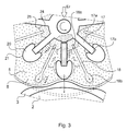
- the driving roller 1 when positioned in an engagement position shown on the figures 1 and 3 , cooperates with obstacles formed on the tread 2, the obstacles here being formed of corrugations 3 extending over a circumference of the tread 2.
- the drive roller 1 At rest, the drive roller 1 has a closed cylindrical outer general shape of axis X, height h and outer radius R.
- the height h is preferably smaller than the outer radius R which gives the drive roller 1 a flattened form.
- the drive roller 1 comprises a central hub 4, a body 5, lateral flanks 6 (one of them is not visible in the figures but is arranged on the opposite non-visible face of the roller) and a fine deformable band 8 with strong resistance to compressive and shear stresses (high tangential stiffness).
- the central hub 4 is a metal part comprising a running portion 9 of generally tubular shape, of axis X and height h. Inside the current portion 9 of the central hub 4 is integrated a splined female sleeve 11. This splined female sleeve 11 is intended to accommodate a drive shaft itself connected to a reduction device 12 (visible on the figure 1 ) to rotate the drive roller 1, transmit a driving torque to the wheel and drive the wheel in rotation.
- the deformable material is here a non-compressible material, adapted to undergo significant compression levels.
- the deformable material here is an elastomer-type material.
- the lateral flanks 6 are metal flanks intended to prevent axial expansion along the X axis of the deformable material forming the body 5, and to increase the rigidity of the drive roller 1 in compression and therefore its resistance to compression stresses but also shear (tangential stresses).
- the lateral flanks are fixed to the central hub 4.
- the deformable strip 8 extends around the body 5 on a circumference of the drive roller 1 or, in other words, extends on the outer cylindrical surface of the cylinder constituting the outer shape of the drive roller 1.
- the deformable strip 8 is here formed of a fabric of metal son.
- First rigid fins 17 and second rigid fins 18 extend radially and are arranged at regular intervals and alternately in the body 5 between the central hub 4 and the deformable strip 8.
- arranged alternately is meant that each first fin 17 is positioned between two second fins 18 and each second fin 18 is positioned between two first fins 17.
- the first fins 17 and the second fins 18 are embedded in the deformable material forming the body 5.
- the first fins 17 each comprise a proximal end 17a fixed to the central hub 4.
- the first fins 17 are integral with the central hub 4.
- Each first fin 17 has a first length less than the thickness of the body 5 (said thickness of the body 5 being equal to the difference between the first radius R and the second radius r), which makes it possible to avoid any contact between a first fin 17 and the deformable band 8 when the deformable strip 8 is in contact with the race 2 when applying a radial force Er on the drive roller 1 and thus on the deformable material of the body 5.
- the deformable strip 8 thus contains the spacing between each second fin 18 during the application of a force radial radial Er on the drive roller 1 and thus on the deformable material of the body 5.
- the circumferential stiffness of the drive roller 1 is thus increased at the periphery of the body 5.
- Each second fin 18 has a second length less than the thickness of the body 5. The second fins 18 can thus move radially when applying a radial force Er on the drive roller 1 and thus on the deformable material of the body 5, while avoiding any interference with the hub central 4.
- the combination of the first fins 17, the second fins 18 and the deformable material of the body 5 makes it possible to transmit a part of the torque by friction but also by meshing, by a conversion of the radial force Er into a tangential force resulting from the interference obtained between the corrugations 3 of the rolling track 2 and the deformable material of the body 5 compressed between these corrugations 3.
- the displacement, under radial force, of the deformable material also makes it possible to increase the contact surface between the driving roller 1 and the rolling track 2.
- the combination of the first fins 17, the second fins 18 and the deformable material of the body 5 also makes it possible to improve the torsional stiffness around the X axis of the deformable material of the body 5 and thus of improve the ability of the latter to transmit torque (tangential or shear force), through work done mainly in compression rather than shear.
- the angular pitch corresponding to the spacing between them of the second fins 18 corresponds to the pitch of the corrugations 3.
- First deformable cavities 20 extend near a distal end 17b of each first fin 17. More specifically, the distal end 17b of each first fin 17 opens into the corresponding first cavity 20.
- Each first cavity 20 is here delimited by a metal insert 21 fixed to the distal end 17b of the first fin 17.
- the first cavities 20 have at rest an elliptical shape of which a greater length extends radially.
- the first cavities 20 are filled with air (or with a material of lower stiffness than the deformable material of the body 5). They deform under the application of a radial force Er on the drive roller 1 and thus on the deformable material of the body 5 and tend to take a circular shape.
- the first cavities 20 thus exert a pressure on the deformable material of the body 5 contained under the axis X by the lateral flanks 6 and therefore increase the pressure exerted on the deformable material of the body 5 and therefore its stiffness in a tangential direction (or torsion) in the areas between the second fins 18, and in an axial direction (or compression) between the flanks 6.
- the capacity of the drive roller 1 to transmit torque is thus improved and the rigidity of the drive roller 1 in torsion and in compression is increased.
- Second deformable cavities 24 extend each at a proximal end 18a of each second fin 18.
- Each second cavity 24 is formed by a pocket 25 disposed in the deformable material of the body 5 extending against the central hub 4 between the proximal ends 17a of two first fins 17.
- the second cavities 24 are filled at least partially with a hydraulic fluid or other material.
- a hydraulic distributor fluidly connects the second cavities 24, that is to say ensures a distribution of hydraulic fluid between the second cavities 24 adjacent.
- the second fin 18 lying perpendicular to the contact between the drive roller 1 and the raceway 2 retracts radially towards the center of the central hub 4 by a distance corresponding to a displacement value of the deformable material of the body 5.
- the second fin 18 then compresses the second cavity 24 located at its proximal end 18a, which has the effect of increasing the pressure in the second adjacent deformable cavities 24 via the hydraulic distributor.
- This increase in pressure in the second adjacent deformable cavities 24 has the opposite effect of projecting the second fins 18 adjacent and stretching the deformable material of the body 5 located at the distal end 18b of the second fins 18 adjacent to in contact with the deformable strip 8 and therefore with the rolling track 2.
- the surface of deformable material of the body 5 in contact with the rolling track 2 (via the deformable strip 8) is thus increased, which makes it possible to distribute the radial force Er to be transmitted over a greater angular portion of the deformable material of the body 5 and to reduce the local stresses within this deformable material of the 5.
- the number of corrugations 3 of the tread 2 in contact with the drive roller 1 is also increased, which promotes the driving ratio of the corrugations 3 and optimizes the efficiency and the proportion of torque transmission by interference.
- the contact surface between the strip of deformable material 8 and the rolling track is also increased, which therefore has the virtuous effect of reducing the local shear (or torsion) stresses due to the transmission of the torque in the thin band of deformable material 8.
- the deformable material of the roller body is not necessarily an elastomer.
- the second fins each have a distal end that extends near the deformable band. It is noted that the distal ends of the second fins may be fixed or not to the deformable strip. They can in particular be fixed to the clean reinforcement of the deformable strip or to any other reinforcement located at the periphery of the two materials of the body 5 and the strip 8.
- this deformable band may be made of any type of deformable material, and may comprise any type of reinforcement: woven or not, embedded, metallic or ceramic, including any type of unidirectional or multidirectional arming material, etc.
- flanks are metal flanks, they can be perfectly manufactured with one or more different materials: composite, armed, fiber, etc.
- the second deformable cavities are each formed by a pocket disposed in the deformable material, they could be perfectly made by simple hollow spaces at the second end of the second fins.
- the rolling track has corrugations, it can be perfectly smooth or rough without ripple.
- the second cavities are fluidly connected to each other by a hydraulic distributor. Note that it is not necessary that all the second cavities are fluidly connected to each other by the same distributor, and it is possible that several distributors connect between them a plurality of second adjacent cavities.
- the fluidic connection is not necessarily performed via a hydraulic distributor but can be by a calibrated restriction system or by one or nozzles.
Landscapes
- Engineering & Computer Science (AREA)
- General Engineering & Computer Science (AREA)
- Mechanical Engineering (AREA)
- Aviation & Aerospace Engineering (AREA)
- Friction Gearing (AREA)
- Rolls And Other Rotary Bodies (AREA)
- Delivering By Means Of Belts And Rollers (AREA)
- Rollers For Roller Conveyors For Transfer (AREA)
Applications Claiming Priority (1)
| Application Number | Priority Date | Filing Date | Title |
|---|---|---|---|
| FR1554273A FR3036152B1 (fr) | 2015-05-12 | 2015-05-12 | Galet d'entrainement. |
Publications (3)
| Publication Number | Publication Date |
|---|---|
| EP3093527A2 true EP3093527A2 (de) | 2016-11-16 |
| EP3093527A3 EP3093527A3 (de) | 2017-03-22 |
| EP3093527B1 EP3093527B1 (de) | 2020-09-09 |
Family
ID=53879629
Family Applications (1)
| Application Number | Title | Priority Date | Filing Date |
|---|---|---|---|
| EP16169213.2A Active EP3093527B1 (de) | 2015-05-12 | 2016-05-11 | Antriebsrolle |
Country Status (4)
| Country | Link |
|---|---|
| US (1) | US10309500B2 (de) |
| EP (1) | EP3093527B1 (de) |
| CN (1) | CN106151424B (de) |
| FR (1) | FR3036152B1 (de) |
Families Citing this family (1)
| Publication number | Priority date | Publication date | Assignee | Title |
|---|---|---|---|---|
| CN113103618B (zh) * | 2021-03-31 | 2022-02-11 | 南京航空航天大学 | 热塑性复合材料原位成型用金属压辊及其设计方法 |
Family Cites Families (27)
| Publication number | Priority date | Publication date | Assignee | Title |
|---|---|---|---|---|
| US1015870A (en) * | 1911-08-10 | 1912-01-30 | Warner Instr Company | Gear. |
| FR980305A (fr) * | 1943-01-22 | 1951-05-10 | Dispositif de transmission de puissance | |
| US2700253A (en) * | 1951-07-12 | 1955-01-25 | Int Harvester Co | Glass fiber drawing apparatus |
| US2794510A (en) * | 1954-03-06 | 1957-06-04 | App Control Equip Moteurs | Friction roller drive means for bicycle having auxiliary engine |
| FR1123876A (fr) * | 1955-03-23 | 1956-10-01 | Hervieu & Cie | Roue et son procédé de fabrication |
| NL105245C (de) * | 1956-02-23 | |||
| US2941440A (en) * | 1959-06-10 | 1960-06-21 | Edward C Scanlon | Braider machine plastic horn gear |
| US3385127A (en) * | 1963-03-06 | 1968-05-28 | Shin Mitsubishi Jukogyo Kk | Gears formed of sheet metal and liquids |
| US3667317A (en) * | 1970-08-26 | 1972-06-06 | Int Harvester Co | Balancer |
| US4108449A (en) * | 1977-01-31 | 1978-08-22 | Rhodes Thomas J | Stair-climbing wheelchair |
| US4412574A (en) * | 1982-09-29 | 1983-11-01 | Gregory Popok | Element for removing dirt or snow from tire, and tire provided therewith |
| US5596905A (en) * | 1994-01-21 | 1997-01-28 | Asahi Kogaku Kogyo Kabushiki Kaisha | Oscillation damping gear |
| US5927149A (en) * | 1995-07-14 | 1999-07-27 | The United States Of America As Represented By The Secretary Of The Navy | High-torque quiet gear |
| US6420846B1 (en) * | 1999-10-19 | 2002-07-16 | Lucas Western Inc. | Power drive unit with stall sensor |
| DE10131331A1 (de) * | 2001-06-28 | 2003-01-09 | Ina Schaeffler Kg | Einrichtung zur Drehmomentübertragung |
| US7159485B2 (en) * | 2003-08-07 | 2007-01-09 | Siemens Vdo Automotive Corporation | Cantilever dampened drive assembly for windowlift motors |
| US20100314014A1 (en) * | 2003-11-28 | 2010-12-16 | Crocodile Corporation Ltd | Tyre |
| JP2006070914A (ja) * | 2004-08-31 | 2006-03-16 | Nidec Nissin Corp | プラスチック歯車 |
| JP2006070915A (ja) * | 2004-08-31 | 2006-03-16 | Nidec Nissin Corp | プラスチック歯車およびプラスチック複合歯車 |
| JP4694520B2 (ja) * | 2007-03-07 | 2011-06-08 | 日産自動車株式会社 | 摩擦伝動変速装置 |
| US8020596B1 (en) * | 2008-10-16 | 2011-09-20 | Glenn Arthur Morrison | High efficiency integrated automotive wheel |
| US8408911B2 (en) * | 2008-10-18 | 2013-04-02 | Steven Gray | Motorcycle wheelie training device |
| FR2939764B1 (fr) * | 2008-12-16 | 2011-10-21 | Airbus | Train d'atterrissage d'aeronef avec motorisation et transmission |
| US8688421B2 (en) * | 2010-03-31 | 2014-04-01 | Compagnie Generale Des Etablissements Michelin | Method to design honeycombs for a shear flexible structure |
| US8555941B2 (en) * | 2010-08-12 | 2013-10-15 | The Boeing Company | Non-pneumatic survivable tire, cover and fabrication processes |
| US9415553B2 (en) * | 2011-05-04 | 2016-08-16 | Compagnie Generale Des Etablissements Michelin | Apparatus and method for curing a rubber like article |
| US20150290982A1 (en) * | 2014-04-12 | 2015-10-15 | Carlayne Sims | Designer tires |
-
2015
- 2015-05-12 FR FR1554273A patent/FR3036152B1/fr active Active
-
2016
- 2016-05-05 US US15/146,966 patent/US10309500B2/en active Active
- 2016-05-11 CN CN201610309139.3A patent/CN106151424B/zh active Active
- 2016-05-11 EP EP16169213.2A patent/EP3093527B1/de active Active
Non-Patent Citations (1)
| Title |
|---|
| None |
Also Published As
| Publication number | Publication date |
|---|---|
| CN106151424B (zh) | 2018-12-14 |
| EP3093527A3 (de) | 2017-03-22 |
| US20160333989A1 (en) | 2016-11-17 |
| CN106151424A (zh) | 2016-11-23 |
| US10309500B2 (en) | 2019-06-04 |
| EP3093527B1 (de) | 2020-09-09 |
| FR3036152A1 (fr) | 2016-11-18 |
| FR3036152B1 (fr) | 2017-06-02 |
Similar Documents
| Publication | Publication Date | Title |
|---|---|---|
| EP2543592B1 (de) | Elektrisches Motorisierungssystem eines Rads | |
| EP2665645B1 (de) | Vorrichtung zum bremsen und zum antrieb eines flugzeugrads | |
| EP3002215B1 (de) | Fahrwerk eines luftfahrzeugs | |
| EP3106325B1 (de) | Pneumatisches system zum befüllen eines reifens, das in eine motorisierte achse integriert ist | |
| FR3036350A1 (fr) | Ensemble servofrein | |
| EP2712745B1 (de) | Lenkstange mit Verstärkungsbuchse | |
| EP3093527B1 (de) | Antriebsrolle | |
| FR2993920A1 (fr) | Helice non carenee a pales a calage variable pour une turbomachine | |
| FR3112744A1 (fr) | Boîtier de transmission et engin roulant équipé d’un tel boîtier de transmission | |
| EP3093528B1 (de) | Antriebsrolle | |
| WO2016097216A1 (fr) | Appareil hydraulique a pistons radiaux comprenant au moins un roulement a billes | |
| EP3565983B1 (de) | Synchronisierte freilaufrolle | |
| FR3056160A1 (fr) | Transmission pour vehicule automobile a propulsion electrique | |
| WO2019201472A1 (fr) | Systeme d'entrainement pour un vehicule automobile hybride et systeme de transmission comprenant un tel systeme d'entrainement | |
| EP3134286B1 (de) | Antriebseinheit für eine motorwelle eines kraftfahrzeugs | |
| WO2017121943A1 (fr) | Synchroniseur de boite de vitesses | |
| EP4055300B1 (de) | Rollenlaufwerkselement | |
| FR3018328A3 (fr) | Differentiel pour vehicule automobile avec dispositif de maintien en position de l'axe porte-satellite | |
| FR3073495B1 (fr) | Atterrisseur d'aeronef | |
| WO2026087431A1 (fr) | Système d'accouplement d'arbres de transmission et procédé de commande d'un tel système d'accouplement d'arbres de transmission | |
| EP3839293A1 (de) | Differentialgehäuse und zugehöriges leitlager | |
| FR3105309A1 (fr) | Machine hydraulique comprenant un organe de défreinage | |
| FR3103870A1 (fr) | Soufflet de protection notamment de joint de transmission | |
| BE624956A (de) |
Legal Events
| Date | Code | Title | Description |
|---|---|---|---|
| PUAI | Public reference made under article 153(3) epc to a published international application that has entered the european phase |
Free format text: ORIGINAL CODE: 0009012 |
|
| AK | Designated contracting states |
Kind code of ref document: A2 Designated state(s): AL AT BE BG CH CY CZ DE DK EE ES FI FR GB GR HR HU IE IS IT LI LT LU LV MC MK MT NL NO PL PT RO RS SE SI SK SM TR |
|
| AX | Request for extension of the european patent |
Extension state: BA ME |
|
| PUAL | Search report despatched |
Free format text: ORIGINAL CODE: 0009013 |
|
| AK | Designated contracting states |
Kind code of ref document: A3 Designated state(s): AL AT BE BG CH CY CZ DE DK EE ES FI FR GB GR HR HU IE IS IT LI LT LU LV MC MK MT NL NO PL PT RO RS SE SI SK SM TR |
|
| AX | Request for extension of the european patent |
Extension state: BA ME |
|
| RIC1 | Information provided on ipc code assigned before grant |
Ipc: F16H 13/02 20060101AFI20170216BHEP Ipc: F16H 55/32 20060101ALI20170216BHEP Ipc: B64C 25/40 20060101ALI20170216BHEP |
|
| STAA | Information on the status of an ep patent application or granted ep patent |
Free format text: STATUS: REQUEST FOR EXAMINATION WAS MADE |
|
| 17P | Request for examination filed |
Effective date: 20170922 |
|
| RBV | Designated contracting states (corrected) |
Designated state(s): AL AT BE BG CH CY CZ DE DK EE ES FI FR GB GR HR HU IE IS IT LI LT LU LV MC MK MT NL NO PL PT RO RS SE SI SK SM TR |
|
| GRAP | Despatch of communication of intention to grant a patent |
Free format text: ORIGINAL CODE: EPIDOSNIGR1 |
|
| STAA | Information on the status of an ep patent application or granted ep patent |
Free format text: STATUS: GRANT OF PATENT IS INTENDED |
|
| INTG | Intention to grant announced |
Effective date: 20200422 |
|
| GRAS | Grant fee paid |
Free format text: ORIGINAL CODE: EPIDOSNIGR3 |
|
| GRAA | (expected) grant |
Free format text: ORIGINAL CODE: 0009210 |
|
| STAA | Information on the status of an ep patent application or granted ep patent |
Free format text: STATUS: THE PATENT HAS BEEN GRANTED |
|
| AK | Designated contracting states |
Kind code of ref document: B1 Designated state(s): AL AT BE BG CH CY CZ DE DK EE ES FI FR GB GR HR HU IE IS IT LI LT LU LV MC MK MT NL NO PL PT RO RS SE SI SK SM TR |
|
| REG | Reference to a national code |
Ref country code: GB Ref legal event code: FG4D Free format text: NOT ENGLISH |
|
| REG | Reference to a national code |
Ref country code: AT Ref legal event code: REF Ref document number: 1311972 Country of ref document: AT Kind code of ref document: T Effective date: 20200915 Ref country code: CH Ref legal event code: EP |
|
| REG | Reference to a national code |
Ref country code: IE Ref legal event code: FG4D Free format text: LANGUAGE OF EP DOCUMENT: FRENCH |
|
| REG | Reference to a national code |
Ref country code: DE Ref legal event code: R096 Ref document number: 602016043564 Country of ref document: DE |
|
| REG | Reference to a national code |
Ref country code: LT Ref legal event code: MG4D |
|
| PG25 | Lapsed in a contracting state [announced via postgrant information from national office to epo] |
Ref country code: NO Free format text: LAPSE BECAUSE OF FAILURE TO SUBMIT A TRANSLATION OF THE DESCRIPTION OR TO PAY THE FEE WITHIN THE PRESCRIBED TIME-LIMIT Effective date: 20201209 Ref country code: FI Free format text: LAPSE BECAUSE OF FAILURE TO SUBMIT A TRANSLATION OF THE DESCRIPTION OR TO PAY THE FEE WITHIN THE PRESCRIBED TIME-LIMIT Effective date: 20200909 Ref country code: LT Free format text: LAPSE BECAUSE OF FAILURE TO SUBMIT A TRANSLATION OF THE DESCRIPTION OR TO PAY THE FEE WITHIN THE PRESCRIBED TIME-LIMIT Effective date: 20200909 Ref country code: HR Free format text: LAPSE BECAUSE OF FAILURE TO SUBMIT A TRANSLATION OF THE DESCRIPTION OR TO PAY THE FEE WITHIN THE PRESCRIBED TIME-LIMIT Effective date: 20200909 Ref country code: SE Free format text: LAPSE BECAUSE OF FAILURE TO SUBMIT A TRANSLATION OF THE DESCRIPTION OR TO PAY THE FEE WITHIN THE PRESCRIBED TIME-LIMIT Effective date: 20200909 Ref country code: BG Free format text: LAPSE BECAUSE OF FAILURE TO SUBMIT A TRANSLATION OF THE DESCRIPTION OR TO PAY THE FEE WITHIN THE PRESCRIBED TIME-LIMIT Effective date: 20201209 Ref country code: GR Free format text: LAPSE BECAUSE OF FAILURE TO SUBMIT A TRANSLATION OF THE DESCRIPTION OR TO PAY THE FEE WITHIN THE PRESCRIBED TIME-LIMIT Effective date: 20201210 |
|
| REG | Reference to a national code |
Ref country code: AT Ref legal event code: MK05 Ref document number: 1311972 Country of ref document: AT Kind code of ref document: T Effective date: 20200909 |
|
| REG | Reference to a national code |
Ref country code: NL Ref legal event code: MP Effective date: 20200909 |
|
| PG25 | Lapsed in a contracting state [announced via postgrant information from national office to epo] |
Ref country code: LV Free format text: LAPSE BECAUSE OF FAILURE TO SUBMIT A TRANSLATION OF THE DESCRIPTION OR TO PAY THE FEE WITHIN THE PRESCRIBED TIME-LIMIT Effective date: 20200909 Ref country code: RS Free format text: LAPSE BECAUSE OF FAILURE TO SUBMIT A TRANSLATION OF THE DESCRIPTION OR TO PAY THE FEE WITHIN THE PRESCRIBED TIME-LIMIT Effective date: 20200909 Ref country code: PL Free format text: LAPSE BECAUSE OF FAILURE TO SUBMIT A TRANSLATION OF THE DESCRIPTION OR TO PAY THE FEE WITHIN THE PRESCRIBED TIME-LIMIT Effective date: 20200909 |
|
| PG25 | Lapsed in a contracting state [announced via postgrant information from national office to epo] |
Ref country code: NL Free format text: LAPSE BECAUSE OF FAILURE TO SUBMIT A TRANSLATION OF THE DESCRIPTION OR TO PAY THE FEE WITHIN THE PRESCRIBED TIME-LIMIT Effective date: 20200909 Ref country code: CZ Free format text: LAPSE BECAUSE OF FAILURE TO SUBMIT A TRANSLATION OF THE DESCRIPTION OR TO PAY THE FEE WITHIN THE PRESCRIBED TIME-LIMIT Effective date: 20200909 Ref country code: PT Free format text: LAPSE BECAUSE OF FAILURE TO SUBMIT A TRANSLATION OF THE DESCRIPTION OR TO PAY THE FEE WITHIN THE PRESCRIBED TIME-LIMIT Effective date: 20210111 Ref country code: RO Free format text: LAPSE BECAUSE OF FAILURE TO SUBMIT A TRANSLATION OF THE DESCRIPTION OR TO PAY THE FEE WITHIN THE PRESCRIBED TIME-LIMIT Effective date: 20200909 Ref country code: SM Free format text: LAPSE BECAUSE OF FAILURE TO SUBMIT A TRANSLATION OF THE DESCRIPTION OR TO PAY THE FEE WITHIN THE PRESCRIBED TIME-LIMIT Effective date: 20200909 Ref country code: EE Free format text: LAPSE BECAUSE OF FAILURE TO SUBMIT A TRANSLATION OF THE DESCRIPTION OR TO PAY THE FEE WITHIN THE PRESCRIBED TIME-LIMIT Effective date: 20200909 |
|
| PG25 | Lapsed in a contracting state [announced via postgrant information from national office to epo] |
Ref country code: ES Free format text: LAPSE BECAUSE OF FAILURE TO SUBMIT A TRANSLATION OF THE DESCRIPTION OR TO PAY THE FEE WITHIN THE PRESCRIBED TIME-LIMIT Effective date: 20200909 Ref country code: AT Free format text: LAPSE BECAUSE OF FAILURE TO SUBMIT A TRANSLATION OF THE DESCRIPTION OR TO PAY THE FEE WITHIN THE PRESCRIBED TIME-LIMIT Effective date: 20200909 Ref country code: AL Free format text: LAPSE BECAUSE OF FAILURE TO SUBMIT A TRANSLATION OF THE DESCRIPTION OR TO PAY THE FEE WITHIN THE PRESCRIBED TIME-LIMIT Effective date: 20200909 Ref country code: IS Free format text: LAPSE BECAUSE OF FAILURE TO SUBMIT A TRANSLATION OF THE DESCRIPTION OR TO PAY THE FEE WITHIN THE PRESCRIBED TIME-LIMIT Effective date: 20210109 |
|
| REG | Reference to a national code |
Ref country code: DE Ref legal event code: R097 Ref document number: 602016043564 Country of ref document: DE |
|
| PG25 | Lapsed in a contracting state [announced via postgrant information from national office to epo] |
Ref country code: SK Free format text: LAPSE BECAUSE OF FAILURE TO SUBMIT A TRANSLATION OF THE DESCRIPTION OR TO PAY THE FEE WITHIN THE PRESCRIBED TIME-LIMIT Effective date: 20200909 |
|
| PLBE | No opposition filed within time limit |
Free format text: ORIGINAL CODE: 0009261 |
|
| STAA | Information on the status of an ep patent application or granted ep patent |
Free format text: STATUS: NO OPPOSITION FILED WITHIN TIME LIMIT |
|
| 26N | No opposition filed |
Effective date: 20210610 |
|
| PG25 | Lapsed in a contracting state [announced via postgrant information from national office to epo] |
Ref country code: DK Free format text: LAPSE BECAUSE OF FAILURE TO SUBMIT A TRANSLATION OF THE DESCRIPTION OR TO PAY THE FEE WITHIN THE PRESCRIBED TIME-LIMIT Effective date: 20200909 Ref country code: SI Free format text: LAPSE BECAUSE OF FAILURE TO SUBMIT A TRANSLATION OF THE DESCRIPTION OR TO PAY THE FEE WITHIN THE PRESCRIBED TIME-LIMIT Effective date: 20200909 |
|
| PG25 | Lapsed in a contracting state [announced via postgrant information from national office to epo] |
Ref country code: IT Free format text: LAPSE BECAUSE OF FAILURE TO SUBMIT A TRANSLATION OF THE DESCRIPTION OR TO PAY THE FEE WITHIN THE PRESCRIBED TIME-LIMIT Effective date: 20200909 |
|
| REG | Reference to a national code |
Ref country code: CH Ref legal event code: PL |
|
| PG25 | Lapsed in a contracting state [announced via postgrant information from national office to epo] |
Ref country code: LI Free format text: LAPSE BECAUSE OF NON-PAYMENT OF DUE FEES Effective date: 20210531 Ref country code: LU Free format text: LAPSE BECAUSE OF NON-PAYMENT OF DUE FEES Effective date: 20210511 Ref country code: MC Free format text: LAPSE BECAUSE OF FAILURE TO SUBMIT A TRANSLATION OF THE DESCRIPTION OR TO PAY THE FEE WITHIN THE PRESCRIBED TIME-LIMIT Effective date: 20200909 Ref country code: CH Free format text: LAPSE BECAUSE OF NON-PAYMENT OF DUE FEES Effective date: 20210531 |
|
| REG | Reference to a national code |
Ref country code: BE Ref legal event code: MM Effective date: 20210531 |
|
| PG25 | Lapsed in a contracting state [announced via postgrant information from national office to epo] |
Ref country code: IE Free format text: LAPSE BECAUSE OF NON-PAYMENT OF DUE FEES Effective date: 20210511 |
|
| PG25 | Lapsed in a contracting state [announced via postgrant information from national office to epo] |
Ref country code: BE Free format text: LAPSE BECAUSE OF NON-PAYMENT OF DUE FEES Effective date: 20210531 |
|
| PG25 | Lapsed in a contracting state [announced via postgrant information from national office to epo] |
Ref country code: HU Free format text: LAPSE BECAUSE OF FAILURE TO SUBMIT A TRANSLATION OF THE DESCRIPTION OR TO PAY THE FEE WITHIN THE PRESCRIBED TIME-LIMIT; INVALID AB INITIO Effective date: 20160511 |
|
| PG25 | Lapsed in a contracting state [announced via postgrant information from national office to epo] |
Ref country code: CY Free format text: LAPSE BECAUSE OF FAILURE TO SUBMIT A TRANSLATION OF THE DESCRIPTION OR TO PAY THE FEE WITHIN THE PRESCRIBED TIME-LIMIT Effective date: 20200909 |
|
| PG25 | Lapsed in a contracting state [announced via postgrant information from national office to epo] |
Ref country code: MK Free format text: LAPSE BECAUSE OF FAILURE TO SUBMIT A TRANSLATION OF THE DESCRIPTION OR TO PAY THE FEE WITHIN THE PRESCRIBED TIME-LIMIT Effective date: 20200909 |
|
| PG25 | Lapsed in a contracting state [announced via postgrant information from national office to epo] |
Ref country code: MT Free format text: LAPSE BECAUSE OF FAILURE TO SUBMIT A TRANSLATION OF THE DESCRIPTION OR TO PAY THE FEE WITHIN THE PRESCRIBED TIME-LIMIT Effective date: 20200909 |
|
| PGFP | Annual fee paid to national office [announced via postgrant information from national office to epo] |
Ref country code: DE Payment date: 20250519 Year of fee payment: 10 |
|
| PGFP | Annual fee paid to national office [announced via postgrant information from national office to epo] |
Ref country code: GB Payment date: 20250527 Year of fee payment: 10 |
|
| PGFP | Annual fee paid to national office [announced via postgrant information from national office to epo] |
Ref country code: FR Payment date: 20250526 Year of fee payment: 10 |
|
| PG25 | Lapsed in a contracting state [announced via postgrant information from national office to epo] |
Ref country code: TR Free format text: LAPSE BECAUSE OF FAILURE TO SUBMIT A TRANSLATION OF THE DESCRIPTION OR TO PAY THE FEE WITHIN THE PRESCRIBED TIME-LIMIT Effective date: 20200909 |