EP3093623B1 - Vorrichtung zur detektion einer winkelposition eines drehorgans, system, das eine solche vorrichtung umfasst, und vorhang, in den ein solches system integriert ist - Google Patents
Vorrichtung zur detektion einer winkelposition eines drehorgans, system, das eine solche vorrichtung umfasst, und vorhang, in den ein solches system integriert ist Download PDFInfo
- Publication number
- EP3093623B1 EP3093623B1 EP16167972.5A EP16167972A EP3093623B1 EP 3093623 B1 EP3093623 B1 EP 3093623B1 EP 16167972 A EP16167972 A EP 16167972A EP 3093623 B1 EP3093623 B1 EP 3093623B1
- Authority
- EP
- European Patent Office
- Prior art keywords
- driven
- stator
- detection device
- rotary member
- driven member
- Prior art date
- Legal status (The legal status is an assumption and is not a legal conclusion. Google has not performed a legal analysis and makes no representation as to the accuracy of the status listed.)
- Not-in-force
Links
Images

Classifications
-
- G—PHYSICS
- G01—MEASURING; TESTING
- G01D—MEASURING NOT SPECIALLY ADAPTED FOR A SPECIFIC VARIABLE; ARRANGEMENTS FOR MEASURING TWO OR MORE VARIABLES NOT COVERED IN A SINGLE OTHER SUBCLASS; TARIFF METERING APPARATUS; MEASURING OR TESTING NOT OTHERWISE PROVIDED FOR
- G01D5/00—Mechanical means for transferring the output of a sensing member; Means for converting the output of a sensing member to another variable where the form or nature of the sensing member does not constrain the means for converting; Transducers not specially adapted for a specific variable
- G01D5/02—Mechanical means for transferring the output of a sensing member; Means for converting the output of a sensing member to another variable where the form or nature of the sensing member does not constrain the means for converting; Transducers not specially adapted for a specific variable using mechanical means
- G01D5/04—Mechanical means for transferring the output of a sensing member; Means for converting the output of a sensing member to another variable where the form or nature of the sensing member does not constrain the means for converting; Transducers not specially adapted for a specific variable using mechanical means using levers; using cams; using gearing
-
- E—FIXED CONSTRUCTIONS
- E06—DOORS, WINDOWS, SHUTTERS, OR ROLLER BLINDS IN GENERAL; LADDERS
- E06B—FIXED OR MOVABLE CLOSURES FOR OPENINGS IN BUILDINGS, VEHICLES, FENCES OR LIKE ENCLOSURES IN GENERAL, e.g. DOORS, WINDOWS, BLINDS, GATES
- E06B9/00—Screening or protective devices for wall or similar openings, with or without operating or securing mechanisms; Closures of similar construction
- E06B9/56—Operating, guiding or securing devices or arrangements for roll-type closures; Spring drums; Tape drums; Counterweighting arrangements therefor
- E06B9/68—Operating devices or mechanisms, e.g. with electric drive
-
- E—FIXED CONSTRUCTIONS
- E06—DOORS, WINDOWS, SHUTTERS, OR ROLLER BLINDS IN GENERAL; LADDERS
- E06B—FIXED OR MOVABLE CLOSURES FOR OPENINGS IN BUILDINGS, VEHICLES, FENCES OR LIKE ENCLOSURES IN GENERAL, e.g. DOORS, WINDOWS, BLINDS, GATES
- E06B9/00—Screening or protective devices for wall or similar openings, with or without operating or securing mechanisms; Closures of similar construction
- E06B9/56—Operating, guiding or securing devices or arrangements for roll-type closures; Spring drums; Tape drums; Counterweighting arrangements therefor
- E06B9/68—Operating devices or mechanisms, e.g. with electric drive
- E06B9/72—Operating devices or mechanisms, e.g. with electric drive comprising an electric motor positioned inside the roller
-
- E—FIXED CONSTRUCTIONS
- E06—DOORS, WINDOWS, SHUTTERS, OR ROLLER BLINDS IN GENERAL; LADDERS
- E06B—FIXED OR MOVABLE CLOSURES FOR OPENINGS IN BUILDINGS, VEHICLES, FENCES OR LIKE ENCLOSURES IN GENERAL, e.g. DOORS, WINDOWS, BLINDS, GATES
- E06B9/00—Screening or protective devices for wall or similar openings, with or without operating or securing mechanisms; Closures of similar construction
- E06B9/56—Operating, guiding or securing devices or arrangements for roll-type closures; Spring drums; Tape drums; Counterweighting arrangements therefor
- E06B9/68—Operating devices or mechanisms, e.g. with electric drive
- E06B2009/6809—Control
- E06B2009/6818—Control using sensors
- E06B2009/6845—Control using sensors sensing position
-
- G—PHYSICS
- G01—MEASURING; TESTING
- G01D—MEASURING NOT SPECIALLY ADAPTED FOR A SPECIFIC VARIABLE; ARRANGEMENTS FOR MEASURING TWO OR MORE VARIABLES NOT COVERED IN A SINGLE OTHER SUBCLASS; TARIFF METERING APPARATUS; MEASURING OR TESTING NOT OTHERWISE PROVIDED FOR
- G01D2205/00—Indexing scheme relating to details of means for transferring or converting the output of a sensing member
- G01D2205/20—Detecting rotary movement
- G01D2205/22—Detecting rotary movement by converting the rotary movement into a linear movement
-
- G—PHYSICS
- G01—MEASURING; TESTING
- G01D—MEASURING NOT SPECIALLY ADAPTED FOR A SPECIFIC VARIABLE; ARRANGEMENTS FOR MEASURING TWO OR MORE VARIABLES NOT COVERED IN A SINGLE OTHER SUBCLASS; TARIFF METERING APPARATUS; MEASURING OR TESTING NOT OTHERWISE PROVIDED FOR
- G01D2205/00—Indexing scheme relating to details of means for transferring or converting the output of a sensing member
- G01D2205/20—Detecting rotary movement
- G01D2205/26—Details of encoders or position sensors specially adapted to detect rotation beyond a full turn of 360°, e.g. multi-rotation
Definitions
- the invention relates to a device for detecting an angular position of a rotary member. It also relates to a system comprising such a device. It also relates to a curtain incorporating such a system.
- the invention lies more particularly in the field of cantonment and compartmentalization of premises. It applies in particular to the cantonment and subdivision of premises in case of fire.
- the invention further relates to a motorization system of a closure equipment by a roll-up curtain.
- End-of-travel detection devices which implement electronic counting. This is not suitable for all applications, especially for safety devices.
- a system of mechanical stops integral with the rotary member is not suitable if it must perform more than one complete turn.
- Another object of the invention is to propose a system combining such a detection device and a motorization device.
- Yet another object of the invention is to propose a curtain with gravitational deployment in lack of current using such a system.
- At least one of the aforementioned objectives is achieved with a device for detecting a position of a member driven by a rotary member on a stroke corresponding to more than one complete revolution of the rotary member.
- the transformation means are such that the driven member passes only once by the predetermined tripping position when the rotary member performs more than one revolution in the same direction.
- the driven member can be conducted between an initial position and the predetermined trigger position and the device according to the invention comprises means for adjusting the initial position of the driven member.
- the device according to the invention may comprise other detection means for detecting the presence of the driven member in at least one other predetermined trigger position close to the predetermined triggering position.
- the detection means may comprise two detectors, one for a command, the other for a signaling.
- the at least one driven member may comprise at least two driven members, to which the motion transformation mechanism confers different movements from one another, and in that the detection means are capable of detecting the presence of each of the two members conducted in at least one respective predetermined position.
- each of the two driven members may correspond to an angular position of the rotary member, and each driven member is movable between its predetermined release position and an initial position which is adjustable to adjust the angular travel of the rotating member. rotating member between the respective two aforementioned angular positions.
- the initial position of the two driven members it is possible to adjust the initial position of only one of the two driven members while the other is in its predetermined tripping position.
- the device according to the invention may comprise an actuator of the detection means, which is biased into the rest position by a spring, and which is placed in the path of the driven member to be driven to a position activation of the detection means when the driven member approaches its predetermined trigger position.
- the device comprises exhaust means for the driven member in the release position, and the spring tends to reengage the driven member with the movement transformation mechanism when the direction of rotation of the rotary member. is reversed. This prevents the detector from being destroyed in the event that the movement of the rotary member continues beyond the trip position.
- the motion transformation mechanism may be of the screw and nut type to transform the rotary motion of the coupling member into a longitudinal movement movement of the driven member.
- the motion transformation mechanism may comprise a screw fixed in an angular position and the driven member comprises an internal thread engaged with the screw and an external toothing which meshes with an elongated pinion axially rotated by the member coupling.
- means may be provided for adjusting the angular position of the screw so as to adjust the initial position of the driven member.
- the elongated pinion can mesh with an internal toothing of the coupling member.
- the screw and nut system can be screw axis parallel to the axis of rotation of the coupling member.
- the detection means may comprise at least one dry contactor connected to three son, one common, the second normally open and the third normally closed.
- a system intended to be mounted in an axial housing of a rotary member, in particular a tube carrier of a roll-up curtain, said system comprising a detection device according to the invention.
- the coupling member can be rotatably supported on the stator by a bearing which is at the same time a bearing bearing the rotary member, while the stator is intended to be fixed to a frame, so that that the detection device is at the same time a support of the rotary member, in particular the carrier tube and the curtain fixed on it.
- system can be essentially housed inside the axial housing, without protruding radially outwardly relative to the axial housing.
- the system according to the invention further comprises, in the axial housing, a motorization device comprising a rotor drive part which, in use, is rotatably coupled to the rotary member for the rotational drive of the rotational member. and a stator part which is connected to the stator of the detection device by a reaction element capable of transmitting the reaction torque of the motor to the stator of the detection device.
- the rotor drive part is located axially beyond the stator part.
- the motorization device can be mounted in the housing of the rotary member.
- the reaction element is a fixed tube extending into the housing.
- the motorization device comprises an external stator motor, the stator part connected to the outer stator surrounds a transmission shaft between the rotor of the motor and the rotor drive part, and at least one bearing is arranged between the part stator and transmission shaft.
- the motorization device may comprise an electric motor.
- the motorization device may further comprise a brake and a gearbox.
- power leads of the driver may extend through the sensing device in an axial channel of the reaction member.
- the system according to the invention allows the coupling of at least one second rotary member at least indirectly to the first rotary member or to the rotor part axially beyond the first rotary member, with respect to the detection device.
- a curtain of gravitational deployment type lack of current equipped with a system according to the second aspect of the invention or one of its improvements, arranged inside.
- the carrier tube of the curtain constituting the rotary member to which the rotor of the detection device and the rotor part of the drive device are coupled.
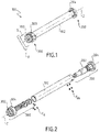
- the figure 1 schematically represents a system 100 according to the invention, in the example of a system for winding and unwinding a roll-up curtain (not shown) of the gravitational deployment type in lack of current.
- the width of the curtain and therefore the axial length of the winding roll can be several meters, and it is often made in segments of for example 1 meter in length, fixed to each other so as to rotate together, preferably fixed rigidly to each other.
- the number of turns made by the winding cylinder 103 between two extreme positions of the curtain is greater than one, and often even equal to several tens, the curtain may have a height unrolled from about 0.5 meters to about 12 meters according to applications.
- the system 100 comprises a detection device 300 according to the invention, which in this application, has the function of detecting the two extreme positions of the roll-up curtain, namely completely wound and fully unwound.
- the detection device 300 has the particularity of being mechanical while being only sensitive to the rotation of the winding roll 103, without being able to use directly fixed stops since the total rotation of the winding roll 103 between the two extreme positions is greater than one round.
- the detection device 300 is designed to be mounted at an axial end of the rotary element, here the winding cylinder 103.
- the detection device 300 is radially non-protruding from the winding cylinder 103.
- the detection device 300 is housed largely inside the winding cylinder 103.
- the detection device 300 comprises a stator 302 provided to be secured to a support S which can be fixed to the frame B, which may be a building wall.
- the stator 302 comprises at its axial end directed towards the outside of the winding cylinder 103 a fixing plate 339 which is fixed to the support S.
- the detection device 300 further comprises a rotor 301 rotatable relative to the stator 302 and having a coupling member 304 adapted to be coupled in rotation with a rotary member constituted by the winding roll 103 of the curtain.
- the coupling member 304 comprises at least one coupling configuration 303 in rotation, here a keyway on the outer surface.
- the coupling member 304 is intended to be in contact with the inner periphery of the winding roll 103.
- the rotor 301 is rotatably supported on the stator 302 by a needle bearing 310 which is at the same time a bearing bearing of the winding roll 103 and the curtain which is in use installed on the winding roll 103.
- the coupling member 304 supports the weight of the winding roll 103 and the curtain, and it is secured to a ring 305, here the outer ring, the needle bearing 310.
- the other ring 322, here the inner ring, of the needle bearing 310 is fixed to the plate 339 by screws 336 which transmit the weight of the curtain and the winding roller 103 to the frame B via the support S.
- the detector 300 according to the invention constitutes a support for the rotary member 103, so that the implementation of the detector 300 according to the invention makes it unnecessary to provide a specific means for supporting in rotation the rotating member at one of its axial ends.
- the detection device 300 further comprises a motion transformation mechanism whose function is to transform the rotation of the winding cylinder 103 into a movement which passes only once through each position when the rotary member, here the cylinder winding 103, performs all of its rotation over several turns between two extreme positions, corresponding here to the two extreme positions of the aforementioned curtain.
- a motion transformation mechanism whose function is to transform the rotation of the winding cylinder 103 into a movement which passes only once through each position when the rotary member, here the cylinder winding 103, performs all of its rotation over several turns between two extreme positions, corresponding here to the two extreme positions of the aforementioned curtain.
- the transformation mechanism transforms the rotational movement of the winding cylinder 103 into a translational movement of at least one driven member, here two bodies led 314 and 316 which move here parallel to the axis Z of the winding cylinder 103.
- the motion transformation mechanism comprises a gear assembly, which in turn comprises an internally ring gear 307 integral with the rotor 301 and which meshes with an elongated gear 312 which is freely rotatably supported by the stator 302 along an axis parallel to the Z axis.
- the elongated pinion 312 extends inwardly of the winding roll 103. It is rotatably supported at one end in a stator body 321 of the stator 302 which is secured to of the plate 339 by screws 338 and the ring 322, and at the other end by a stator piece 309 of the stator 302 which is secured to the stator body 305 by rods 311 forming a cage.
- the motion transformation mechanism further comprises two driven pinions 314 and 316, which here constitute the aforementioned driven members and which mesh with the elongated pinion 312.
- the driven pinions 314 and 316 have threads which are each threaded with a respective screws 318 and 320 supported by the stator 302, and more precisely having one end supported by the stator body 321 and the other end supported by the stator part 309.
- the screws 318 and 320 are fixed in operation and have steps in opposite directions to one another, so that the pinions 314 and 316, which always rotate in the same direction for a direction of rotation of the ring 307 and of the elongate pinion 312, move axially in opposite directions to each other along the screws 318 and 320.
- the elongated pinion 312 is sufficiently long to always mesh with the driven pinions 314 and 316, regardless of their position on the along the screws 318 and 320.
- the two screws 318 and 320 are arranged parallel to the elongated pinion 312 and symmetrically with respect to a plane passing through the axis Z and the axis of the elongated pinion 312.
- Rotation of the rotatable member 103 in one direction results in axial displacement in one direction of one of the driven gears and axial displacement in the opposite direction of the other driven gear. If the rotational member 103 rotates in the opposite direction, the axial displacements of the driven gears are also reversed, respectively.
- Each driven member 314, 316 is axially movable between a predetermined release position, here close to the stator piece 309, and an initial position which is adjustable to adjust the angular travel of the rotational member between the respective two aforementioned angular positions.
- the initial position of each driven member 314, 316 is set separately while the other is in its predetermined trigger position.
- the detection device 300 comprises in this embodiment a rotational mounting of each of the two screws 318 and 320 in the stator body 321 and the stator part 309.
- a rotation of the screw 318, 320 makes it possible to axially move the corresponding driven gear 314, 316 while the latter is prevented from rotating, because of its meshing with the elongate pinion 312, which is stationary during such a setting operation.
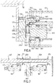
- each is coupled, here by a toothed gear 333 ( figure 6 ), with a setting knob 334 rotatably mounted in the stator 302.
- the adjusting knob 334 is rotatably braked by a spring 335 which maintains a degree of friction in the rotation of the adjusting knob 334.
- the adjustment knob 334 is operated with a screwdriver.
- each driven member is adjusted so that the number of revolutions of the winding roll such as 103 which is necessary for the driven member to move from its initial position to its trigger position corresponds to the number of turns of the cylinder. winding 103 between the two desired extreme positions, here the upper position and the lower position of the curtain respectively.
- the detection device 300 comprises detection means which comprise two pairs of detectors N1, N2 respectively N3, N4, fixed to the stator 302, here to the stator piece 309, and two pairs of flags D1, D2 respectively D3, D4.
- the detector N1 is not represented.
- the detectors N1 and N3 are used to transmit a control signal while the detectors N2 and N4 are used to transmit a signaling.
- the detectors N1, N2, N3, N4 each comprise a dry contactor connected to three wires, one common, the second normally open, that is to say normally disconnected from the common, and the third normally closed, that is ie normally connected to the common.
- Each pair of flags D1, D2 or respectively D3, D4 is produced by means of a substantially cylindrical piece 324, respectively 326, on which the flags are made in the form of end flanges.
- the parts 324 and 326 constitute actuators of the detectors N1, N2, N3, N4. They are returned to a rest position by two springs 328 and 330.
- Parts 324 and 326 are placed in the paths of the driven members 314 and 316 to be driven to an activation position of the flag detection means as the driven members 314 and 316 approach their predetermined release positions.
- Each actuator 324, respectively 326, is slidably mounted around the screw 318, respectively 320 corresponding.
- the detectors N1, N2 respectively N3, N4 comprise levers L1, L2 (not shown), respectively L3, L4.
- the levers L1, L2 are arranged so that the flag D1, respectively D2, presses the lever L1, respectively L2, when the actuator is pushed by the driven pinion 314 arriving at the end of the trigger stroke on the corresponding screw 318.
- the levers L3 and L4 are arranged in the same manner, with respect to the flags D3 and D4 and to the driven member 316.
- the detectors N1, N2, N3 and N4 detect the presence of the driven members 314 and 316 in a predetermined trigger position.
- the levers L1, L2 are arranged so that the flag D1, presses the lever L1 prior to the support by the flag D2 on the lever L2. This is achieved by a spacing between the two levers L1 and L2 which is different from, here greater than, that between the two flags D1 and D2 corresponding.
- the levers L3 and L4 are arranged in the same manner, with respect to the flags D3 and D4 and to the driven member 316.
- the detectors N1, N2, N3 and N4 detect the presence of the driven members 314 and 316 in at least one other position of predetermined tripping close to the predetermined tripping position.
- the screws 318 and 320 have a periphery hollowed in the vicinity of the actuators.
- the actuator return spring pushes the driven member in the direction of reengaging on the thread of the screw.
- Detection device 300 is now described in a functional manner.
- the winding roll 103 is rotated in the appropriate direction and drives the coupling member 304.
- the ring gear 307 meshes with the external toothing of the elongated gear 312, which drives the two pinions 314 and 316 in rotation via the external teeth of the two gears.
- the two gears 314 and 316 being engaged with the screws 318 and 320 with opposite pitch, their movements are opposite.
- one of the pinions 314 or 316 is in initial position while the other pinion 316 or 314 solicits the corresponding actuator, whose flags D1, D2, or respectively D3, D4 cause a detection of the a respective end of the race.
- the system 100 further comprises a drive device 200 comprising a drive rotor portion 204 rotatably coupled with the winding roller 103 by a key 207 (FIG. figure 4 ) integral with the winding cylinder 103 and engaged in a conformation, here a groove 205, of the drive rotor portion 204.
- a drive device 200 comprising a drive rotor portion 204 rotatably coupled with the winding roller 103 by a key 207 (FIG. figure 4 ) integral with the winding cylinder 103 and engaged in a conformation, here a groove 205, of the drive rotor portion 204.
- the motorization device is coaxial with the Z axis of the detection device 300. It comprises the stator part 202 which is non-rotatably coupled to the stator 302 of the detection device 300 by a reaction element 102 which is here a fixed tube 102 which extends axially inside the winding roll 103.
- the stator 302 and the stator part 202 are rigidly fixed to the fixed tube 102.
- the drive device 200 is fully housed in the axial inner housing of the winding cylinder 103 beyond, and even at a distance beyond the distal end (i.e. detectors) of the detection device, said distance being a function of the length of the reaction tube 102.
- Feeding wires 209 of the actuator 200 extend into the reaction tube 102 to exit the system 100 via a passage (no completely shown) through the stator 302, comprising a central orifice 313 of the plate 339 ( figure 5 ), as the wires connected to detectors D1 to D4.
- the rotary drive portion 204 is disposed axially opposite the detection device 300.
- the motorization device comprises a motor 208 and a reducer 211 having an output shaft 213 directed away from the detector 300.
- the reaction tube 102 substantially envelops the actuator 200 and the sensing device 300 with the exception of the driver portions 204 and 304 which each protrude at a respective end of the tube 102.
- the actuator 200 and the device 300 are of very generally cylindrical conformation and are adapted to be at least partially nested in the reaction tube 102, each at one of its ends, as illustrated by FIG. figure 1 and as just described.
- the reaction tube 102 is fixed on the outer surface of the ring 206.
- the motorization device 200 comprises the stator part 202 and a rotor part (not shown) comprising the drive part 204.
- the stator part 202 comprises, axially and from left to right on the figure 3 , an electric motor stator 208 and an outer ring of a bearing 206 of the winding cylinder 103.
- the bearing 206 supports in rotation by two bearings 214 a transmission shaft 212 fixed to the shaft 213 of the geared motor, and connecting it to the drive part 204.
- the motor 208 is less than 48 volts voltage and includes a brake.
- the motor 208 can be adapted to a load range necessary to raise the curtain.
- the drive shaft 212 is further mounted keyed on the output shaft 213 of the reducer 211 and on the rotary drive portion 204.
- the bearing 206 is disposed axially between the motor 208 and the reducer 211 on the one hand, and the rotary drive part 204 on the other hand.
- the motorization device 200 is now described in a functional manner.
- the load of the curtain is sufficient for the the curtain unfolds and drives the rotational driving portion 204 in rotation by means of the winding cylinder 103.
- the motor 208 functions as a dynamo which then generates current. This generation is performed by induction of current in the solenoid of the motor 208. This current is regulated passively, that is to say without power supply, in order to obtain a desired descent speed.
- a security is activated during an impromptu meeting before the complete descent of the curtain to the selected position and the motor brake 208 is then activated.
- the motor stops after detection of this position by the detection device 300 and the position is maintained by the motor brake 208.
- This position may for example correspond to the alignment of the curtain with the level of a false ceiling.
Landscapes
- Engineering & Computer Science (AREA)
- Structural Engineering (AREA)
- Architecture (AREA)
- Civil Engineering (AREA)
- Physics & Mathematics (AREA)
- General Physics & Mathematics (AREA)
- Operating, Guiding And Securing Of Roll- Type Closing Members (AREA)
- Curtains And Furnishings For Windows Or Doors (AREA)
Claims (16)
- Vorrichtung (300) zur Erkennung einer Position eines von einem Drehorgan (103) angetriebenen Elements entlang eines Weges, der mehr als einer vollen Umdrehung des Drehorgans (103) entspricht, dadurch gekennzeichnet, dass sie aufweist:- einen Stator (302),- ein Kopplungsorgan (304), das in Bezug auf den Stator (302) drehend bewegbar ist und in der Lage ist, mit dem Drehorgan (103) drehgekoppelt zu werden,- einen Bewegungsumwandlungsmechanismus, der funktionell zwischen dem Kopplungsorgan (304) und mindestens einem geführten Organ (314, 316) angeordnet ist,- Erkennungseinrichtungen zum Erkennen des Vorhandenseins mindestens eines geführten Organs (314, 316) in einer vorbestimmten Auslöseposition,wobei die Umwandlungseinrichtungen derart ausgebildet sind, dass das geführte Organ (314, 316) die vorbestimmte Auslöseposition nur ein einziges Mal passiert, während das Drehorgan (103) mehr als eine Umdrehung in der gleichen Richtung durchführt, wobei das geführte Organ (314, 316) zwischen einer Ausgangsposition und der vorbestimmten Auslöseposition geführt ist,
dadurch gekennzeichnet, dass
die Vorrichtung (300) Einrichtungen zum Einstellen der Ausgangsposition des geführten Organs (314, 316) aufweist. - Erkennungsvorrichtung nach dem vorhergehenden Anspruch, mit anderen Erkennungseinrichtungen zum Erkennen des Vorhandenseins des geführten Organs (314, 316) in mindestens einer anderen vorbestimmten Auslöseposition, die der vorbestimmten Auslöseposition benachbart ist.
- Vorrichtung nach Anspruch 1 oder 2, bei welcher die Erkennungseinrichtungen für jedes geführte Organ (314, 316) zwei Detektoren N1, N2, N3, N4) aufweisen, einen zur Steuerung, den anderen zu Signalgebung.
- Erkennungsvorrichtung nach einem der vorhergehenden Ansprüche, bei welcher das mindestens eine geführte Organ (314, 316) mindestens zwei geführte Organe (314, 316) aufweist und der Bewegungsumwandlungsmechanismus den beiden geführten Organen (314, 316) voneinander verschiedene Bewegungen vermittelt, und wobei die Erkennungseinrichtungen geeignet sind das Vorhandensein jedes der beiden geführten Organe (314, 316) an mindestens einer der jeweiligen vorbestimmten Positionen zu erkennen.
- Erkennungsvorrichtung nach dem vorangehenden Anspruch, dadurch gekennzeichnet, dass die vorbestimmte Position jedes der beiden geführten Organe (314, 316) einer jeweiligen Winkelposition des Drehorgans (103) entspricht, und dass jedes geführte Organ (314, 316) zwischen seiner vorbestimmten Auslöseposition und einer Ausgangsposition bewegbar ist, welche zum Einstellen des Winkelwegs des Drehorgans zwischen den beiden genannten jeweiligen Winkelpositionen einstellbar ist.
- Vorrichtung nach dem vorangehenden Anspruch, bei welcher zur Einstellung der Ausgangsposition der beiden geführten Organe (314, 316) die Ausgangsposition eines einzelnen der geführten Organe (314, 316) eingestellt wird, während das andere in seiner vorbestimmten Auslöseposition ist.
- Vorrichtung nach einem der vorhergehenden Ansprüche, mit einem Aktuator (324, 326) der Erkennungseinrichtungen (308), der durch eine Feder (328, 330) in eine Ruheposition vorgespannt ist, und der in der Bahn des geführten Organs (314, 316) angeordnet ist, um in Richtung einer Aktivierungsposition der Erkennungseinrichtungen angetrieben zu werden, wenn das geführte Organ (314, 316) sich seiner vorbestimmten Auslöseposition nähert.
- Vorrichtung nach dem vorangehenden Anspruch, mit Hemmeinrichtungen für das geführte Organ in der Auslöseposition, und wobei die Feder geeignet ist, das geführte Organ wieder in Eingriff mit dem Bewegungsumwandlungsmechanismus zu bringen, wenn sich die Drehrichtung des Drehorgans umkehrt.
- Vorrichtung nach einem der vorhergehenden Ansprüche, bei welcher der Bewegungsumwandlungsmechanismus vom Spindelgetriebetyp ist, um die Drehbewegung des Kopplungsorgans (304) in eine längsgerichtete Verschiebungsbewegung des geführten Organs (314, 316) umzuwandeln.
- Vorrichtung nach dem vorangehenden Anspruch, in Kombination mit Anspruch 5 oder 6, bei welcher der Bewegungsumwandlungsmechanismus eine in einer Winkelposition fixierte Spindel (318, 320) aufweist und das geführte Organ (314, 316) ein Innengewinde, das mit der Spindel in Eingriff ist, und eine Außenverzahnung aufweist, die mit einem in axialer Richtung langgestreckten Zahnrad (312) kämmt, das von dem Kopplungsorgan (304) drehend angetrieben ist, wobei die Vorrichtung ferner Einrichtungen (333; 334; 335) aufweist, welche dazu vorgesehen sind, die Position der Spindel (318, 320) einzustellen, um die Ausgangsposition des geführten Organs (314, 316) einzustellen.
- Vorrichtung nach einem der vorhergehenden Ansprüche, bei welcher die Erkennungseinrichtungen mindestens einen trockenen Kontakt aufweisen, der mit drei Drähten verbunden ist, von denen der eine ein gemeinsamer Draht, der zweite normalerweise offen und der dritte normalerweise geschlossen ist.
- System (100) zum Einbau in einer axialen Aufnahme eines Drehorgans (103), insbesondere eines Trägerrohres eines aufrollbaren Vorhangs, wobei das System eine Erkennungsvorrichtung (300) nach einem der vorhergehenden Ansprüche aufweist, dadurch gekennzeichnet, dass das Kopplungsorgan (304) an dem Stator (302) durch ein Lager (332) drehbar gestützt ist, das gleichzeitig ein Stützlager des Drehorgans (103) ist, während der Stator (302) zur Befestigung an einem umgebenden Gehäuse (B) vorgesehen ist, derart, dass die Erkennungsvorrichtung (300) gleichzeitig eine Stütze für das Drehorgan (103) insbesondere für das Trägerrohr und den daran befestigten Vorhang bildet.
- System nach dem vorangehenden Anspruch, wobei das System (100) im Wesentlichen im Inneren der axialen Aufnahme aufgenommen ist, ohne in Bezug auf die axiale Aufnahme radial nach außen zu ragen.
- System nach Anspruch 12 oder 13, ferner mit einer Motorantriebsvorrichtung (200) in der axialen Aufnahme, mit einem Antriebsrotorteil (204), welches im Gebrauch drehend mit dem Drehorgan gekoppelt ist, um dieses drehend anzutreiben, und einem Statorteil, das mit dem Stator (302) der Erkennungsvorrichtung (300) durch ein Reaktionselement (102) verbunden ist, das in der Lage ist, an den Stator der Erkennungsvorrichtung das Reaktionsdrehmoment des Motors zu übertragen, und wobei die Motorantriebsvorrichtung (200) einen Motor (208) mit äußerem Stator aufweist, und wobei das mit dem äußeren Stator verbundene Statorteil eine Antriebswelle (212) zwischen dem Rotor des Motors (208) und dem Antriebsrotorteil (204) umgibt, und wobei mindestens ein Lager (214, 216) zwischen dem Statorteil (206) und der Antriebswelle (212) angeordnet ist.
- System nach dem vorangehenden Anspruch, bei welchem Versorgungskabel (209) der Motorantriebsvorrichtung (200) durch die Erkennungsvorrichtung (300) in einem axialen Kanal des Reaktionselements (102) verlaufen.
- Vorhang von dem Typ, der bei fehlendem Strom unter Schwerkraftwirkung aufgerollt wird, mit einem System nach einem der Ansprüche 12 bis 15, das im Inneren des Vorhangträgerrohres (103) angeordnet ist, welches das Drehorgan bildet, mit welchem der Rotor der Erkennungsvorrichtung (300) und das Rotorteil der Motorantriebsvorrichtung (200) gekoppelt sind.
Applications Claiming Priority (1)
| Application Number | Priority Date | Filing Date | Title |
|---|---|---|---|
| FR1554331A FR3036182A1 (fr) | 2015-05-13 | 2015-05-13 | Dispositif de detection d'une position angulaire d'un organe rotatif, systeme comprenant un tel dispositif et rideau integrant un tel systeme |
Publications (2)
| Publication Number | Publication Date |
|---|---|
| EP3093623A1 EP3093623A1 (de) | 2016-11-16 |
| EP3093623B1 true EP3093623B1 (de) | 2018-03-14 |
Family
ID=53776769
Family Applications (1)
| Application Number | Title | Priority Date | Filing Date |
|---|---|---|---|
| EP16167972.5A Not-in-force EP3093623B1 (de) | 2015-05-13 | 2016-05-02 | Vorrichtung zur detektion einer winkelposition eines drehorgans, system, das eine solche vorrichtung umfasst, und vorhang, in den ein solches system integriert ist |
Country Status (2)
| Country | Link |
|---|---|
| EP (1) | EP3093623B1 (de) |
| FR (1) | FR3036182A1 (de) |
Families Citing this family (2)
| Publication number | Priority date | Publication date | Assignee | Title |
|---|---|---|---|---|
| CN109011260A (zh) * | 2018-10-22 | 2018-12-18 | 重庆理工大学 | 一种用于新能源汽车锂离子电池感温自启动灭火装置的探火管 |
| FR3105287B1 (fr) * | 2019-12-23 | 2023-04-14 | Somfy Activites Sa | Actionneur électromécanique d’entraînement d’un écran de fermeture ou de protection solaire, installation de fermeture ou de protection solaire comprenant un tel actionneur et procédé de dimensionnement d’un ressort de compensation d’une gamme de stores intégrant, chacun, un tel actionneur |
Family Cites Families (4)
| Publication number | Priority date | Publication date | Assignee | Title |
|---|---|---|---|---|
| US5121558A (en) * | 1990-09-07 | 1992-06-16 | Agc Industries, Inc. | Method and apparatus for controlling and indicating angular rotation of a shaft |
| FR2756320A1 (fr) * | 1996-11-25 | 1998-05-29 | Deprat Jean Sa | Dispositif de detection de fin de course et mecanisme d'entrainement de volet roulant incorporant un tel dispositif |
| US7443160B2 (en) * | 2006-09-28 | 2008-10-28 | Wolf Ronald J | Position sensor |
| DE102012202634A1 (de) * | 2012-02-21 | 2013-08-22 | Robert Bosch Gmbh | Sensoranordnung zur Erfassung von Drehwinkeln an einem rotierenden Bauteil in einem Fahrzeug |
-
2015
- 2015-05-13 FR FR1554331A patent/FR3036182A1/fr not_active Withdrawn
-
2016
- 2016-05-02 EP EP16167972.5A patent/EP3093623B1/de not_active Not-in-force
Non-Patent Citations (1)
| Title |
|---|
| None * |
Also Published As
| Publication number | Publication date |
|---|---|
| FR3036182A1 (fr) | 2016-11-18 |
| EP3093623A1 (de) | 2016-11-16 |
Similar Documents
| Publication | Publication Date | Title |
|---|---|---|
| CH642714A5 (fr) | Dispositif d'entrainement, pour stores a rouleau ou volets roulants. | |
| EP2148413B1 (de) | Integriertes lineares elektrisches Stellglied | |
| EP3093623B1 (de) | Vorrichtung zur detektion einer winkelposition eines drehorgans, system, das eine solche vorrichtung umfasst, und vorhang, in den ein solches system integriert ist | |
| FR2557397A1 (fr) | Procede pour la commande d'un moteur d'entrainement de rouleaux et dispositif de commande pour la mise en oeuvre dudit procede | |
| CH661572A5 (fr) | Actionneur lineaire a systeme vis-ecrou. | |
| EP0748921A1 (de) | Motorisierte Aufrolleinrichtung mit einer einstellbaren automatischen Abschalteinrichtung | |
| EP0497711B1 (de) | Sicherungseinrichtung für elektrische Betätigungseinrichtung für Rolläden | |
| EP0229681B1 (de) | Antriebsvorrichtung zum Drehen der Rolle eines Rolladens, Rollstores oder dergleichen | |
| EP1422375B1 (de) | Motorischer Stellantrieb einer Abschlussvorrichtung für eine Offnung in einem Fahrzeug und entsprechende Tür und Fahrzeug | |
| EP0775798B1 (de) | Drehantriebsvorrichtung zum Drehen der Rolle eines Rolladens | |
| FR2755998A1 (fr) | Dispositif d'arret automatique d'un moteur entrainant un tube d'enroulement d'un volet roulant | |
| EP2503091A1 (de) | Betätigungsvorrichtung für Verschluss- oder Sonnenschutzanlage, und mit einer solchen Vorrichtung ausgestattete Verschluss- oder Sonnenschutzanlage | |
| EP1676013B1 (de) | Vorrichtung zur steuerung des öffnens eines beweglichen elements, wie zum beispiel einer rauchabzugsklappe | |
| EP3821104B1 (de) | Antriebssystem zum antreiben eines bildschirms und vorrichtung mit einem solchen system | |
| FR2740824A1 (fr) | Installation de fermeture ou de protection solaire motorisee | |
| WO2003027428A1 (fr) | Dispositif d'accouplement elastique destine a aligner deux pieces en rotation | |
| EP1640555B1 (de) | Drive with automatic clutch for a building closure | |
| FR2500877A1 (fr) | Dispositif de verrouillage de portes centralise, notamment pour portieres de vehicules automobiles | |
| EP2546452A2 (de) | Schaltelement für einen Motorblock eines Innen- oder Außenrolladens mit Lamellen | |
| FR3087474A1 (fr) | Procede de controle d'un systeme d'actionnement d'un premier et d'un second ecrans et systeme d'actionnement | |
| FR2756320A1 (fr) | Dispositif de detection de fin de course et mecanisme d'entrainement de volet roulant incorporant un tel dispositif | |
| FR2561303A3 (fr) | Dispositif d'enroulement pour des rideaux ou des stores enroulables | |
| FR3014937A1 (fr) | Fin de course d'enroulement ou de deroulement de tablier de systeme d'occultation | |
| CH628115A5 (en) | Electric device for winding up Venetian blinds | |
| FR2755177A1 (fr) | Volet roulant a commande electrique et dispositif de demultiplication pour un tel volet |
Legal Events
| Date | Code | Title | Description |
|---|---|---|---|
| PUAI | Public reference made under article 153(3) epc to a published international application that has entered the european phase |
Free format text: ORIGINAL CODE: 0009012 |
|
| 17P | Request for examination filed |
Effective date: 20160502 |
|
| AK | Designated contracting states |
Kind code of ref document: A1 Designated state(s): AL AT BE BG CH CY CZ DE DK EE ES FI FR GB GR HR HU IE IS IT LI LT LU LV MC MK MT NL NO PL PT RO RS SE SI SK SM TR |
|
| AX | Request for extension of the european patent |
Extension state: BA ME |
|
| GRAP | Despatch of communication of intention to grant a patent |
Free format text: ORIGINAL CODE: EPIDOSNIGR1 |
|
| INTG | Intention to grant announced |
Effective date: 20170612 |
|
| GRAS | Grant fee paid |
Free format text: ORIGINAL CODE: EPIDOSNIGR3 |
|
| GRAJ | Information related to disapproval of communication of intention to grant by the applicant or resumption of examination proceedings by the epo deleted |
Free format text: ORIGINAL CODE: EPIDOSDIGR1 |
|
| GRAL | Information related to payment of fee for publishing/printing deleted |
Free format text: ORIGINAL CODE: EPIDOSDIGR3 |
|
| INTC | Intention to grant announced (deleted) | ||
| GRAP | Despatch of communication of intention to grant a patent |
Free format text: ORIGINAL CODE: EPIDOSNIGR1 |
|
| RAP1 | Party data changed (applicant data changed or rights of an application transferred) |
Owner name: SOUCHIER-BOULLET |
|
| INTG | Intention to grant announced |
Effective date: 20180103 |
|
| GRAA | (expected) grant |
Free format text: ORIGINAL CODE: 0009210 |
|
| AK | Designated contracting states |
Kind code of ref document: B1 Designated state(s): AL AT BE BG CH CY CZ DE DK EE ES FI FR GB GR HR HU IE IS IT LI LT LU LV MC MK MT NL NO PL PT RO RS SE SI SK SM TR |
|
| REG | Reference to a national code |
Ref country code: GB Ref legal event code: FG4D Free format text: NOT ENGLISH |
|
| REG | Reference to a national code |
Ref country code: CH Ref legal event code: EP Ref country code: AT Ref legal event code: REF Ref document number: 979348 Country of ref document: AT Kind code of ref document: T Effective date: 20180315 |
|
| REG | Reference to a national code |
Ref country code: IE Ref legal event code: FG4D Free format text: LANGUAGE OF EP DOCUMENT: FRENCH |
|
| REG | Reference to a national code |
Ref country code: DE Ref legal event code: R096 Ref document number: 602016001948 Country of ref document: DE |
|
| REG | Reference to a national code |
Ref country code: FR Ref legal event code: PLFP Year of fee payment: 3 |
|
| REG | Reference to a national code |
Ref country code: NL Ref legal event code: MP Effective date: 20180314 |
|
| REG | Reference to a national code |
Ref country code: LT Ref legal event code: MG4D |
|
| PG25 | Lapsed in a contracting state [announced via postgrant information from national office to epo] |
Ref country code: FI Free format text: LAPSE BECAUSE OF FAILURE TO SUBMIT A TRANSLATION OF THE DESCRIPTION OR TO PAY THE FEE WITHIN THE PRESCRIBED TIME-LIMIT Effective date: 20180314 Ref country code: CY Free format text: LAPSE BECAUSE OF FAILURE TO SUBMIT A TRANSLATION OF THE DESCRIPTION OR TO PAY THE FEE WITHIN THE PRESCRIBED TIME-LIMIT Effective date: 20180314 Ref country code: NO Free format text: LAPSE BECAUSE OF FAILURE TO SUBMIT A TRANSLATION OF THE DESCRIPTION OR TO PAY THE FEE WITHIN THE PRESCRIBED TIME-LIMIT Effective date: 20180614 Ref country code: LT Free format text: LAPSE BECAUSE OF FAILURE TO SUBMIT A TRANSLATION OF THE DESCRIPTION OR TO PAY THE FEE WITHIN THE PRESCRIBED TIME-LIMIT Effective date: 20180314 Ref country code: HR Free format text: LAPSE BECAUSE OF FAILURE TO SUBMIT A TRANSLATION OF THE DESCRIPTION OR TO PAY THE FEE WITHIN THE PRESCRIBED TIME-LIMIT Effective date: 20180314 |
|
| REG | Reference to a national code |
Ref country code: AT Ref legal event code: MK05 Ref document number: 979348 Country of ref document: AT Kind code of ref document: T Effective date: 20180314 |
|
| PG25 | Lapsed in a contracting state [announced via postgrant information from national office to epo] |
Ref country code: GR Free format text: LAPSE BECAUSE OF FAILURE TO SUBMIT A TRANSLATION OF THE DESCRIPTION OR TO PAY THE FEE WITHIN THE PRESCRIBED TIME-LIMIT Effective date: 20180615 Ref country code: SE Free format text: LAPSE BECAUSE OF FAILURE TO SUBMIT A TRANSLATION OF THE DESCRIPTION OR TO PAY THE FEE WITHIN THE PRESCRIBED TIME-LIMIT Effective date: 20180314 Ref country code: RS Free format text: LAPSE BECAUSE OF FAILURE TO SUBMIT A TRANSLATION OF THE DESCRIPTION OR TO PAY THE FEE WITHIN THE PRESCRIBED TIME-LIMIT Effective date: 20180314 Ref country code: BG Free format text: LAPSE BECAUSE OF FAILURE TO SUBMIT A TRANSLATION OF THE DESCRIPTION OR TO PAY THE FEE WITHIN THE PRESCRIBED TIME-LIMIT Effective date: 20180614 Ref country code: LV Free format text: LAPSE BECAUSE OF FAILURE TO SUBMIT A TRANSLATION OF THE DESCRIPTION OR TO PAY THE FEE WITHIN THE PRESCRIBED TIME-LIMIT Effective date: 20180314 |
|
| PG25 | Lapsed in a contracting state [announced via postgrant information from national office to epo] |
Ref country code: MT Free format text: LAPSE BECAUSE OF FAILURE TO SUBMIT A TRANSLATION OF THE DESCRIPTION OR TO PAY THE FEE WITHIN THE PRESCRIBED TIME-LIMIT Effective date: 20180314 |
|
| PG25 | Lapsed in a contracting state [announced via postgrant information from national office to epo] |
Ref country code: NL Free format text: LAPSE BECAUSE OF FAILURE TO SUBMIT A TRANSLATION OF THE DESCRIPTION OR TO PAY THE FEE WITHIN THE PRESCRIBED TIME-LIMIT Effective date: 20180314 Ref country code: PL Free format text: LAPSE BECAUSE OF FAILURE TO SUBMIT A TRANSLATION OF THE DESCRIPTION OR TO PAY THE FEE WITHIN THE PRESCRIBED TIME-LIMIT Effective date: 20180314 Ref country code: ES Free format text: LAPSE BECAUSE OF FAILURE TO SUBMIT A TRANSLATION OF THE DESCRIPTION OR TO PAY THE FEE WITHIN THE PRESCRIBED TIME-LIMIT Effective date: 20180314 Ref country code: EE Free format text: LAPSE BECAUSE OF FAILURE TO SUBMIT A TRANSLATION OF THE DESCRIPTION OR TO PAY THE FEE WITHIN THE PRESCRIBED TIME-LIMIT Effective date: 20180314 Ref country code: IT Free format text: LAPSE BECAUSE OF FAILURE TO SUBMIT A TRANSLATION OF THE DESCRIPTION OR TO PAY THE FEE WITHIN THE PRESCRIBED TIME-LIMIT Effective date: 20180314 Ref country code: RO Free format text: LAPSE BECAUSE OF FAILURE TO SUBMIT A TRANSLATION OF THE DESCRIPTION OR TO PAY THE FEE WITHIN THE PRESCRIBED TIME-LIMIT Effective date: 20180314 Ref country code: AL Free format text: LAPSE BECAUSE OF FAILURE TO SUBMIT A TRANSLATION OF THE DESCRIPTION OR TO PAY THE FEE WITHIN THE PRESCRIBED TIME-LIMIT Effective date: 20180314 |
|
| PG25 | Lapsed in a contracting state [announced via postgrant information from national office to epo] |
Ref country code: CZ Free format text: LAPSE BECAUSE OF FAILURE TO SUBMIT A TRANSLATION OF THE DESCRIPTION OR TO PAY THE FEE WITHIN THE PRESCRIBED TIME-LIMIT Effective date: 20180314 Ref country code: SK Free format text: LAPSE BECAUSE OF FAILURE TO SUBMIT A TRANSLATION OF THE DESCRIPTION OR TO PAY THE FEE WITHIN THE PRESCRIBED TIME-LIMIT Effective date: 20180314 Ref country code: SM Free format text: LAPSE BECAUSE OF FAILURE TO SUBMIT A TRANSLATION OF THE DESCRIPTION OR TO PAY THE FEE WITHIN THE PRESCRIBED TIME-LIMIT Effective date: 20180314 Ref country code: AT Free format text: LAPSE BECAUSE OF FAILURE TO SUBMIT A TRANSLATION OF THE DESCRIPTION OR TO PAY THE FEE WITHIN THE PRESCRIBED TIME-LIMIT Effective date: 20180314 |
|
| REG | Reference to a national code |
Ref country code: DE Ref legal event code: R097 Ref document number: 602016001948 Country of ref document: DE |
|
| PG25 | Lapsed in a contracting state [announced via postgrant information from national office to epo] |
Ref country code: PT Free format text: LAPSE BECAUSE OF FAILURE TO SUBMIT A TRANSLATION OF THE DESCRIPTION OR TO PAY THE FEE WITHIN THE PRESCRIBED TIME-LIMIT Effective date: 20180716 |
|
| PLBE | No opposition filed within time limit |
Free format text: ORIGINAL CODE: 0009261 |
|
| STAA | Information on the status of an ep patent application or granted ep patent |
Free format text: STATUS: NO OPPOSITION FILED WITHIN TIME LIMIT |
|
| REG | Reference to a national code |
Ref country code: BE Ref legal event code: MM Effective date: 20180531 |
|
| PG25 | Lapsed in a contracting state [announced via postgrant information from national office to epo] |
Ref country code: MC Free format text: LAPSE BECAUSE OF FAILURE TO SUBMIT A TRANSLATION OF THE DESCRIPTION OR TO PAY THE FEE WITHIN THE PRESCRIBED TIME-LIMIT Effective date: 20180314 Ref country code: DK Free format text: LAPSE BECAUSE OF FAILURE TO SUBMIT A TRANSLATION OF THE DESCRIPTION OR TO PAY THE FEE WITHIN THE PRESCRIBED TIME-LIMIT Effective date: 20180314 |
|
| 26N | No opposition filed |
Effective date: 20181217 |
|
| REG | Reference to a national code |
Ref country code: IE Ref legal event code: MM4A |
|
| PG25 | Lapsed in a contracting state [announced via postgrant information from national office to epo] |
Ref country code: SI Free format text: LAPSE BECAUSE OF FAILURE TO SUBMIT A TRANSLATION OF THE DESCRIPTION OR TO PAY THE FEE WITHIN THE PRESCRIBED TIME-LIMIT Effective date: 20180314 |
|
| PG25 | Lapsed in a contracting state [announced via postgrant information from national office to epo] |
Ref country code: LU Free format text: LAPSE BECAUSE OF NON-PAYMENT OF DUE FEES Effective date: 20180502 |
|
| PG25 | Lapsed in a contracting state [announced via postgrant information from national office to epo] |
Ref country code: IE Free format text: LAPSE BECAUSE OF NON-PAYMENT OF DUE FEES Effective date: 20180502 |
|
| PG25 | Lapsed in a contracting state [announced via postgrant information from national office to epo] |
Ref country code: BE Free format text: LAPSE BECAUSE OF NON-PAYMENT OF DUE FEES Effective date: 20180531 |
|
| REG | Reference to a national code |
Ref country code: CH Ref legal event code: PL |
|
| PG25 | Lapsed in a contracting state [announced via postgrant information from national office to epo] |
Ref country code: CH Free format text: LAPSE BECAUSE OF NON-PAYMENT OF DUE FEES Effective date: 20190531 Ref country code: LI Free format text: LAPSE BECAUSE OF NON-PAYMENT OF DUE FEES Effective date: 20190531 |
|
| PG25 | Lapsed in a contracting state [announced via postgrant information from national office to epo] |
Ref country code: TR Free format text: LAPSE BECAUSE OF FAILURE TO SUBMIT A TRANSLATION OF THE DESCRIPTION OR TO PAY THE FEE WITHIN THE PRESCRIBED TIME-LIMIT Effective date: 20180314 |
|
| PG25 | Lapsed in a contracting state [announced via postgrant information from national office to epo] |
Ref country code: HU Free format text: LAPSE BECAUSE OF FAILURE TO SUBMIT A TRANSLATION OF THE DESCRIPTION OR TO PAY THE FEE WITHIN THE PRESCRIBED TIME-LIMIT; INVALID AB INITIO Effective date: 20160502 Ref country code: MK Free format text: LAPSE BECAUSE OF NON-PAYMENT OF DUE FEES Effective date: 20180314 |
|
| PG25 | Lapsed in a contracting state [announced via postgrant information from national office to epo] |
Ref country code: IS Free format text: LAPSE BECAUSE OF FAILURE TO SUBMIT A TRANSLATION OF THE DESCRIPTION OR TO PAY THE FEE WITHIN THE PRESCRIBED TIME-LIMIT Effective date: 20180714 |
|
| PGFP | Annual fee paid to national office [announced via postgrant information from national office to epo] |
Ref country code: FR Payment date: 20230526 Year of fee payment: 8 Ref country code: DE Payment date: 20230526 Year of fee payment: 8 |
|
| PGFP | Annual fee paid to national office [announced via postgrant information from national office to epo] |
Ref country code: GB Payment date: 20230530 Year of fee payment: 8 |
|
| REG | Reference to a national code |
Ref country code: DE Ref legal event code: R119 Ref document number: 602016001948 Country of ref document: DE |
|
| GBPC | Gb: european patent ceased through non-payment of renewal fee |
Effective date: 20240502 |
|
| PG25 | Lapsed in a contracting state [announced via postgrant information from national office to epo] |
Ref country code: DE Free format text: LAPSE BECAUSE OF NON-PAYMENT OF DUE FEES Effective date: 20241203 |
|
| PG25 | Lapsed in a contracting state [announced via postgrant information from national office to epo] |
Ref country code: FR Free format text: LAPSE BECAUSE OF NON-PAYMENT OF DUE FEES Effective date: 20240531 |
|
| PG25 | Lapsed in a contracting state [announced via postgrant information from national office to epo] |
Ref country code: GB Free format text: LAPSE BECAUSE OF NON-PAYMENT OF DUE FEES Effective date: 20240502 |