EP3093631A1 - Haushaltswaage mit abnehmbarem behälter zur optimierten lagerung - Google Patents
Haushaltswaage mit abnehmbarem behälter zur optimierten lagerung Download PDFInfo
- Publication number
- EP3093631A1 EP3093631A1 EP15305712.0A EP15305712A EP3093631A1 EP 3093631 A1 EP3093631 A1 EP 3093631A1 EP 15305712 A EP15305712 A EP 15305712A EP 3093631 A1 EP3093631 A1 EP 3093631A1
- Authority
- EP
- European Patent Office
- Prior art keywords
- container
- support
- balance according
- household
- chamfer
- Prior art date
- Legal status (The legal status is an assumption and is not a legal conclusion. Google has not performed a legal analysis and makes no representation as to the accuracy of the status listed.)
- Withdrawn
Links
- 238000003860 storage Methods 0.000 title claims abstract description 30
- 239000004615 ingredient Substances 0.000 claims abstract description 10
- 238000005259 measurement Methods 0.000 claims abstract description 6
- 230000005291 magnetic effect Effects 0.000 claims description 26
- 239000002184 metal Substances 0.000 claims description 20
- 230000000295 complement effect Effects 0.000 claims description 18
- 230000002093 peripheral effect Effects 0.000 claims description 10
- 239000003302 ferromagnetic material Substances 0.000 claims description 7
- 238000005303 weighing Methods 0.000 description 12
- 230000005294 ferromagnetic effect Effects 0.000 description 8
- 239000000725 suspension Substances 0.000 description 4
- 238000004140 cleaning Methods 0.000 description 2
- 238000010276 construction Methods 0.000 description 2
- 235000013305 food Nutrition 0.000 description 2
- 230000005484 gravity Effects 0.000 description 2
- 238000004519 manufacturing process Methods 0.000 description 2
- 239000007787 solid Substances 0.000 description 2
- 230000009471 action Effects 0.000 description 1
- 238000004026 adhesive bonding Methods 0.000 description 1
- 230000008901 benefit Effects 0.000 description 1
- 238000010586 diagram Methods 0.000 description 1
- 238000009826 distribution Methods 0.000 description 1
- 235000013312 flour Nutrition 0.000 description 1
- 230000006698 induction Effects 0.000 description 1
- 239000007788 liquid Substances 0.000 description 1
- 239000004973 liquid crystal related substance Substances 0.000 description 1
- 239000000463 material Substances 0.000 description 1
- 238000000034 method Methods 0.000 description 1
- 238000012986 modification Methods 0.000 description 1
- 230000004048 modification Effects 0.000 description 1
- 230000009467 reduction Effects 0.000 description 1
- 238000000926 separation method Methods 0.000 description 1
Images


Classifications
-
- G—PHYSICS
- G01—MEASURING; TESTING
- G01G—WEIGHING
- G01G21/00—Details of weighing apparatus
- G01G21/22—Weigh pans or other weighing receptacles; Weighing platforms
Definitions
- the present invention relates to the technical field of weighing devices, more particularly a household balance.
- Apparatuses of the aforementioned type generally comprise a plate adapted to receive a weight, a device for measuring the weight present on the plate comprising a display means for displaying the measured weight and control or adjustment means.
- a container intended to contain the ingredient or articles to be weighed so that they are not in direct contact with the tray for reasons of hygiene, practicality and cleanability. This is particularly necessary since the ingredient to be weighed is loose and hardly stands on the tray. It may be for example solid ingredients such as flour, powdered sugar or pieces, or liquid ingredients ....
- said container is weighed at the same time as the food and display of the result takes into account a reduction of the container weight.
- the container is often removable from the weighing device to facilitate cleaning the container and transporting the food to be weighed.
- the object of the present invention is to provide a weighing device easy to store and move and with its removable container.
- Another object of the invention is a weighing apparatus with reduced space when it is stored or moved.
- Another object of the invention is a container containing articles to be weighed adapted to a wall suspension while remaining attached to a weighing apparatus.
- the term "container” means a plate-like container having a substantially flat bottom and inclined edges, for retaining an ingredient to be weighed in bulk.
- the container follows the movement and position of the carrier without falling.
- the container undergoes only gravity and can be easily moved from the support because it is not attached to the support, it can be slid on the support.
- the balance can be stored in a position other than the horizontal position without the container being apart: the container remains in contact with the support in any position.
- the scale can be hung or suspended on the wall with the container without the container falling.
- said connecting means exert a magnetic force and the container comprises complementary connecting means undergoing said magnetic force, so that said magnetic force makes it possible to retain the container only when it is in the storage position.
- the complementary connection means are provided to undergo - respectively not to undergo - the magnetic force of the connecting means by a reference distance between the two means allowing the connecting means to act in storage position on the complementary connecting means and respectively enabling the connecting means not to act in a storage position on the complementary connection means.
- a separation distance studied according to the two positions and in Magnetic force function is provided.
- the connecting means comprise at least one permanent magnet.
- the complementary connection means comprise at least one part composed of ferromagnetic material.
- said support has a first planar surface and a first peripheral bevel to the first planar surface and said at least one magnet is arranged adjacent to the bevel
- the container has a second planar surface and a second peripheral bevel. the second flat surface and said at least one part is arranged at its periphery.
- Said chamfers have a slope shape.
- the fact of putting the active and passive means at the chamfers and at the periphery makes it possible to optimize the distribution of force and the number of materials used. Also, the force acts only at the chamfer, at the periphery of the support.
- said at least one magnet has a parallelepipedal shape of which at least one face is substantially parallel to said first chamfer.
- the connecting means comprise at least two permanent magnets; the complementary connecting means comprise at least two metal parts; the magnets and metal parts being arranged so that the magnet and the metal part of each pair are facing each other in the storage position.
- the magnet and the metal part can then face each other so that the magnetic force is exerted in a maximal way. This makes it possible to optimize the magnetic force in the storage position.
- the magnets and metal parts are regularly distributed on the periphery of the support and the container.
- first chamfer and the second chamfer are oriented to be substantially parallel in the storage position.
- the container substantially covers the entire support, that is to say, the second flat surface covers the first flat surface and the second chamfer covers the first chamfer.
- the first chamfer and the second chamfer are oriented at an angle ( ⁇ ) of between 20 ° and 70 ° with respect to the flat surfaces in the position of use, more particularly between 40 ° and 50 ° for example equal to 45 °.
- ⁇ angle of between 20 ° and 70 ° with respect to the flat surfaces in the position of use, more particularly between 40 ° and 50 ° for example equal to 45 °.
- the carrier has a disc shape with a chamfer periphery and the container has a disc shape with a chamfer periphery.
- the support and the container respectively have a substantially circular flat surface and a substantially circular peripheral bevel.
- the number of magnets is greater than three, for example equal to five in order to accentuate the magnetic force for a stronger and stable attachment.
- the magnets can then be identical.
- At least the second peripheral chamfer is entirely metallic, more particularly the entire container is metallic.
- said support has a first planar surface and said connecting means are arranged adjacent to said planar surface, and said container has a flat bottom and an inclined wall, said at least one part made of ferromagnetic material being arranged at the level of said planar bottom.
- said container comprises between said inclined wall and the bottom plane means for distancing the support for moving the flat bottom of the first flat surface by a distance (d) between 2mm and 5mm in the position of use.
- said distancing means comprise folds protruding from the plane background intended to make contact with the support in the position of use.
- the first flat surface has a circular shape and the container has a disk-like shape with an inclined wall periphery, the largest diameter of the inclined wall being greater than that of the first planar surface.
- At least the flat bottom is entirely metallic, more particularly the entire container is metallic.
- the balance comprises on the housing a hooking means such as a hook for a wall suspension.
- a household balance as illustrated in figure 1 and generally designated by the reference 10 comprises a housing 1 defining a frame 12 of generally circular shape intended to rest on a working plane horizontally during use, a support 4 in the form of a round tray supported by the chassis 12.
- the balance 10 further comprises a weighing device comprising at least one weight sensor connected to a weight measurement system connected to a display unit 3 result linked to the measure.
- the display unit 3 may comprise a liquid crystal display.
- Around the display unit 3 are arranged control keys 6, 7 of different functions.
- the balance 10 comprises at the end of the housing 1 a hooking means 5 having a shape of a half-circle or half-ring for a wall suspension.
- Said frame 12 supports the weighing device which comprises an electronic circuit 8 powered by batteries and sensors assembled in the frame 12.
- the sensors comprise strain gauges connected to the electronic circuit 8 by cabling. During a weighing of a weight, the strain gauges are deformed under the action of the weight and modify the electrical signal measured by the electronic circuit 8 which then calculates the weight present on the support 4 and displays it on the display.
- a container 20 is available to the user to put the article or the ingredient to be weighed.
- Said container 20 has a plate-like shape with a circular flat bottom and an edge and can be moved easily during use to transport the weight to be weighed or for cleaning.
- the support has a first planar surface (S1) and a first peripheral bevel 41 while the container has a second planar surface (S2) and a second bevel 21 device.
- the two flat surfaces (S1, S2) have substantially the same diameter so that one is plumb with the other when the container 20 is placed on the support 4.
- the figure 2 illustrates the position of use in which the container 20 is placed freely on the support 4.
- the container 20 can also take another position called storage position in which the container 20 is held attached to the support by the magnetic force. In this position, the container is able to follow the position of the scale even if it is in a different position than the horizontal, for example when the scale is suspended on the wall.
- the support 4 comprises connecting means 11 comprising a series of five permanent magnets 11 exerting a magnetic force, the magnets 11 being evenly distributed on the periphery of the support 4 at the first chamfer 41.
- the container 20 comprises complementary connecting means 21 on the second peripheral groove 21 undergoing the magnetic force.
- Said complementary connecting means 21 comprise at least one part 21 made of ferromagnetic material.
- the vessel is entirely ferromagnetic metal or at least the second circumferential bevel 21 is entirely ferromagnetic metal.
- first and second chamfers are oriented at an angle ⁇ relative to the flat surfaces which is substantially equal to 45 ° as in the example illustrated in FIG. figure 4 .
- the two chamfers are substantially parallel in the storage position.
- each magnet has a parallelepipedal shape of which at least one face 11a is substantially parallel to the first chamfer 41.
- the magnets are then arranged inside the support at the chamfer and do not make contact with, or at least do not exercise of magnetic force on the first flat surface (S1). That is, the magnets 11 are functional only in the storage position when the container 20 is turned upside down as in the figure 5 .
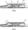
- the support 4 has a first flat surface (S1) intended to receive the container 20.
- Said container 20 according to the second embodiment has a flat bottom 22 and an inclined wall 23.
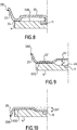
- the container 20 has means of distancing 24 of the support 4 which are folds in protuberance 24 relative to the bottom plane 22 on the opposite side to the inclined wall 23.
- the protruding pleats 24 contact the support 4, which allows the planar bottom 22 of the first flat surface (S1) to be displaced by a distance d as visible in FIG. figure 8 .
- This gap allows to escape the magnetic attraction, it is between 2mm and 5mm.
- the use position according to the second embodiment is illustrated in FIG. figure 6 .
- the container 20 When the container 20 is in the storage position, it can be returned to be placed on the support 4 as shown in FIG. figure 7 . This time, it is the bottom plane 22 of the container which makes contact with the first flat surface (S1).
- the inclined wall 23 has a greater perimeter than that of the first flat surface (S1).
- the widths of the inclined wall 23 are greater than the corresponding widths of the first flat surface (S1).
- the first flat surface (S1) has a circular shape and the container 20 takes the form of a disc with the flat bottom 22 and the inclined wall 23 circular.
- the largest diameter of the inclined wall 23 is greater than that of the first planar surface (S1).
- At least one magnet 11 is arranged adjacent to said first planar surface (S1) and the complementary connecting means 22 comprise at least one part 22 made of the ferromagnetic metal located on the bottom plane 22.
- the container is entirely ferromagnetic metal or at least the planar bottom 22 is entirely ferromagnetic metal.
- the magnet 11 is arranged in the center of the support 4, but it can be arranged on the entire surface of the support 4 and sufficiently distant from the distancing means.
- the container 20 has a planar bottom 22 'and an inclined wall 23.
- the container 20 has complementary connecting means 24' of the support 4 presented in the form of a protruding central zone 24 'of a distance 1 2d 'with respect to the flat bottom 22' and on the same side as the inclined wall 23.
- the support 4 has a first flat surface (S1) and a hollow central zone 45 having a shape complementary to that of the central zone. protuberance 24 'of the container 20. The depth of said hollow central zone 45 is 1 / 2d'.
- the container 20 When the container 20 is in the storage position, it can be returned to be placed on the support 4 as shown in FIG. figure 10 . This time, the whole of the bottom plane 22 'and the central protruding zone 24' of the container respectively contact the first flat surface (S1) and the hollow central zone 45 of the support 4.
- the inclined wall 23 has a perimeter greater than that of the first flat surface (S1). For example, in the case where the flat bottom 22 and the first flat surface (S1) are square or rectangular, the widths of the inclined wall 23 are greater than the corresponding widths of the first flat surface (S1).
- the first flat surface (S1) has a circular shape and the container 20 takes the form of a disc with the circular bottom plane 23 'and the inclined wall 23.
- the largest diameter of the inclined wall 23 is greater than that of the first planar surface (S1).
- At least one magnet 11 is arranged adjacent to said first planar surface (S1) in the hollow central zone 45 and the complementary connecting means 24 'comprise at least one portion 24' made of the ferromagnetic metal located on the protruding central zone 24 '.
- the container is entirely ferromagnetic metal or at least the protruding central zone 24 'is entirely ferromagnetic metal.
- the magnet 11 is arranged in the center of the support 4, but it can be arranged over the entire hollow central zone 45.
- the magnets have characteristics that respect the template of the scale while ensuring the attachment of the container.
- each magnet has a dimension of 6x8x17mm, and a remanent magnetic induction level of 0.4 to 1.4 Tesla.
- the magnets are attached to the support by gluing but could be attached by any other method of attachment within the reach of those skilled in the art, for example the pegging.
- a weighing assembly comprising a scale and a container as described above.
- the balance and the container each have geometric and technical characteristics enabling the container to take both positions, ie the position of use and the storage position.
- the container may also be offered individually as a spare part in case of loss or damage thereof.
Landscapes
- Physics & Mathematics (AREA)
- General Physics & Mathematics (AREA)
- Details Of Rigid Or Semi-Rigid Containers (AREA)
Priority Applications (1)
| Application Number | Priority Date | Filing Date | Title |
|---|---|---|---|
| EP15305712.0A EP3093631A1 (de) | 2015-05-12 | 2015-05-12 | Haushaltswaage mit abnehmbarem behälter zur optimierten lagerung |
Applications Claiming Priority (1)
| Application Number | Priority Date | Filing Date | Title |
|---|---|---|---|
| EP15305712.0A EP3093631A1 (de) | 2015-05-12 | 2015-05-12 | Haushaltswaage mit abnehmbarem behälter zur optimierten lagerung |
Publications (1)
| Publication Number | Publication Date |
|---|---|
| EP3093631A1 true EP3093631A1 (de) | 2016-11-16 |
Family
ID=53191617
Family Applications (1)
| Application Number | Title | Priority Date | Filing Date |
|---|---|---|---|
| EP15305712.0A Withdrawn EP3093631A1 (de) | 2015-05-12 | 2015-05-12 | Haushaltswaage mit abnehmbarem behälter zur optimierten lagerung |
Country Status (1)
| Country | Link |
|---|---|
| EP (1) | EP3093631A1 (de) |
Citations (4)
| Publication number | Priority date | Publication date | Assignee | Title |
|---|---|---|---|---|
| US5410108A (en) * | 1992-08-31 | 1995-04-25 | Spectra-Physics Scanning Systems, Inc. | Combined scanner and scale |
| US20040035614A1 (en) * | 2002-08-22 | 2004-02-26 | Bin Zhang | Portable scale |
| FR2932565A1 (fr) | 2008-06-13 | 2009-12-18 | Seb Sa | Appareil de pesage a interface interactive. |
| CH699565A1 (de) * | 2008-09-25 | 2010-03-31 | Carag Ag | Waagschale und Waage. |
-
2015
- 2015-05-12 EP EP15305712.0A patent/EP3093631A1/de not_active Withdrawn
Patent Citations (4)
| Publication number | Priority date | Publication date | Assignee | Title |
|---|---|---|---|---|
| US5410108A (en) * | 1992-08-31 | 1995-04-25 | Spectra-Physics Scanning Systems, Inc. | Combined scanner and scale |
| US20040035614A1 (en) * | 2002-08-22 | 2004-02-26 | Bin Zhang | Portable scale |
| FR2932565A1 (fr) | 2008-06-13 | 2009-12-18 | Seb Sa | Appareil de pesage a interface interactive. |
| CH699565A1 (de) * | 2008-09-25 | 2010-03-31 | Carag Ag | Waagschale und Waage. |
Similar Documents
| Publication | Publication Date | Title |
|---|---|---|
| US9719843B2 (en) | Optimized household scale with removable storage container | |
| EP3093631A1 (de) | Haushaltswaage mit abnehmbarem behälter zur optimierten lagerung | |
| AU2013358927B2 (en) | Decorative transparent dinnerware articles with interchangeable display capability | |
| EP3387395B1 (de) | Elektronische waage mit einer deckplatte | |
| USD527228S1 (en) | Vertical utensil rest | |
| FR2958521A1 (fr) | Dispositif de liaison ou d'extension pour modules de preparation et de cuisson | |
| FR3055593A1 (fr) | Table comportant un ecran tactile pivotant en haut d'un pied et destinee a equiper un moyen de transport | |
| CN208938217U (zh) | 一种重力传感器支架机构、商品贩卖设备以及无人售货系统 | |
| EP0739805A1 (de) | Einkaufswagen | |
| FR2649659A1 (fr) | Chariot pliant | |
| CN106289490A (zh) | 具有最优化储存的可拆卸的容器的家用秤 | |
| EP2407070A1 (de) | Kochelement, insbesondere für Elektrokochgerät | |
| EP1694172B1 (de) | Vorrichtung zur darbietung von gegenständen | |
| EP0219656B1 (de) | Autographisches Register | |
| FR3031161A1 (fr) | Tablette pour porter des objets au-dessus d'un support de type ecran de television ou d'ordinateur | |
| FR3044212A1 (fr) | Presentoir | |
| FR2641114A1 (de) | ||
| FR2538233A1 (fr) | Dispositif de presentation de produits alimentaires, notamment caves a vin | |
| WO1996032042A1 (fr) | Dispositif de plateau destine plus particulierement a la preparation de sauces et d'assaisonnements de plats | |
| NL1025318C2 (nl) | Presenteerblad voor thee. | |
| FR3105398A1 (fr) | Dispositif et systeme electronique de pesee a socles communicants | |
| FR2800717A1 (fr) | Boite contenant un produit alimentaire dosable par mesurette | |
| FR3055784A1 (fr) | Presentoir a condiments | |
| FR2920655A1 (fr) | Ustensile de service a table d'assiettes en liaison chaude | |
| FR2813859A1 (fr) | Dispositif d'emballage et de presentation en rayonnage d'un ensemble de garnitures de porte |
Legal Events
| Date | Code | Title | Description |
|---|---|---|---|
| PUAI | Public reference made under article 153(3) epc to a published international application that has entered the european phase |
Free format text: ORIGINAL CODE: 0009012 |
|
| AK | Designated contracting states |
Kind code of ref document: A1 Designated state(s): AL AT BE BG CH CY CZ DE DK EE ES FI FR GB GR HR HU IE IS IT LI LT LU LV MC MK MT NL NO PL PT RO RS SE SI SK SM TR |
|
| AX | Request for extension of the european patent |
Extension state: BA ME |
|
| 17P | Request for examination filed |
Effective date: 20170511 |
|
| RBV | Designated contracting states (corrected) |
Designated state(s): AL AT BE BG CH CY CZ DE DK EE ES FI FR GB GR HR HU IE IS IT LI LT LU LV MC MK MT NL NO PL PT RO RS SE SI SK SM TR |
|
| 17Q | First examination report despatched |
Effective date: 20191210 |
|
| STAA | Information on the status of an ep patent application or granted ep patent |
Free format text: STATUS: THE APPLICATION IS DEEMED TO BE WITHDRAWN |
|
| 18D | Application deemed to be withdrawn |
Effective date: 20200603 |