EP3093632B1 - Wiegevorrichtung mit anwendungseinheiten - Google Patents
Wiegevorrichtung mit anwendungseinheiten Download PDFInfo
- Publication number
- EP3093632B1 EP3093632B1 EP15167066.8A EP15167066A EP3093632B1 EP 3093632 B1 EP3093632 B1 EP 3093632B1 EP 15167066 A EP15167066 A EP 15167066A EP 3093632 B1 EP3093632 B1 EP 3093632B1
- Authority
- EP
- European Patent Office
- Prior art keywords
- unit
- weighing
- power
- receiving
- coil
- Prior art date
- Legal status (The legal status is an assumption and is not a legal conclusion. Google has not performed a legal analysis and makes no representation as to the accuracy of the status listed.)
- Active
Links
Images


Classifications
-
- G—PHYSICS
- G01—MEASURING; TESTING
- G01G—WEIGHING
- G01G19/00—Weighing apparatus or methods adapted for special purposes not provided for in the preceding groups
-
- G—PHYSICS
- G01—MEASURING; TESTING
- G01G—WEIGHING
- G01G21/00—Details of weighing apparatus
- G01G21/22—Weigh pans or other weighing receptacles; Weighing platforms
-
- G—PHYSICS
- G01—MEASURING; TESTING
- G01G—WEIGHING
- G01G21/00—Details of weighing apparatus
- G01G21/28—Frames, Housings
-
- G—PHYSICS
- G01—MEASURING; TESTING
- G01G—WEIGHING
- G01G23/00—Auxiliary devices for weighing apparatus
-
- G—PHYSICS
- G01—MEASURING; TESTING
- G01G—WEIGHING
- G01G23/00—Auxiliary devices for weighing apparatus
- G01G23/007—Integrated arrangements for generating electrical power, e.g. solar cells
-
- H—ELECTRICITY
- H01—ELECTRIC ELEMENTS
- H01F—MAGNETS; INDUCTANCES; TRANSFORMERS; SELECTION OF MATERIALS FOR THEIR MAGNETIC PROPERTIES
- H01F38/00—Adaptations of transformers or inductances for specific applications or functions
- H01F38/14—Inductive couplings
-
- H02J5/005—
-
- H—ELECTRICITY
- H02—GENERATION; CONVERSION OR DISTRIBUTION OF ELECTRIC POWER
- H02J—ELECTRIC POWER NETWORKS; CIRCUIT ARRANGEMENTS OR SYSTEMS FOR SUPPLYING OR DISTRIBUTING ELECTRIC POWER; SYSTEMS FOR STORING ELECTRIC ENERGY
- H02J50/00—Circuit arrangements or systems for wireless supply or distribution of electric power
- H02J50/10—Circuit arrangements or systems for wireless supply or distribution of electric power using inductive coupling
-
- H—ELECTRICITY
- H02—GENERATION; CONVERSION OR DISTRIBUTION OF ELECTRIC POWER
- H02J—ELECTRIC POWER NETWORKS; CIRCUIT ARRANGEMENTS OR SYSTEMS FOR SUPPLYING OR DISTRIBUTING ELECTRIC POWER; SYSTEMS FOR STORING ELECTRIC ENERGY
- H02J50/00—Circuit arrangements or systems for wireless supply or distribution of electric power
- H02J50/80—Circuit arrangements or systems for wireless supply or distribution of electric power involving the exchange of data, concerning supply or distribution of electric power, between transmitting devices and receiving devices
-
- G—PHYSICS
- G01—MEASURING; TESTING
- G01G—WEIGHING
- G01G17/00—Apparatus for or methods of weighing material of special form or property
- G01G17/04—Apparatus for or methods of weighing material of special form or property for weighing fluids, e.g. gases, pastes
- G01G17/06—Apparatus for or methods of weighing material of special form or property for weighing fluids, e.g. gases, pastes having means for controlling the supply or discharge
Definitions
- the invention concerns a weighing device which is used in laboratories.
- Weighing devices are commonly used in laboratories to determine the weight or weight change of a sample. Furthermore, in laboratories, there is usually a need to carry out plural operations on the same sample. For example, there might be a need to weigh a sample and additionally also to magnetically stir or dispense or any such operation on the sample. Instead of using multiple devices for carrying out these different operations on the same sample, a single device can be used.
- the weighing device As a laboratory device to be operated by a laboratory expert, and depending on the particular circumstances at the given laboratory, it may be desired that the different application units be placed where they are most favourably situated for the user.
- this conflicts with the fact that, to operate the weighing device, the flow of data and power between the application units of the weighing device must be maintained.
- the installation of power or data lines for the transmission of signals is expensive and space consuming.
- the present invention discusses a weighing device according to the independent claims.
- a weighing device comprising a weighing unit, a control unit and at least one application unit.
- Such an application unit is comprised within a secondary unit; this secondary unit also comprises a receiving unit.
- the control unit comprises a data transmitting unit.
- the weighing unit comprises load receivers and a power transmitting unit.
- the secondary unit is placed on the load receivers of the weighing unit leaving a gap between the top side of the weighing unit and the bottom side of the secondary unit.
- the weighing unit transmits a power signal from the power transmitting unit to the receiving unit of the secondary unit through the gap and a control signal is transmitted from the data transmitting unit to the receiving unit of the secondary unit through the gap.
- the secondary unit and in turn the application unit is thus powered and controlled contactless by the weighing unit and the control unit respectively.
- An advantageous feature of the present invention is that due to the contactless powering and controlling of the application unit by the weighing unit and control unit respectively, the weighing device becomes compact and non-bulky due to absence of cables or cords for power and data transfer.
- the power transmitting unit comprises at least one sending coil. This sending coil is placed towards a top side of the weighing unit facing a bottom side of the secondary unit.
- the power transmitting unit is used for transmitting the power signal from the weighing unit towards the secondary unit using the sending coil.
- the advantage of the placement of the sending coil towards the top side of the weighing unit is to assist in the process of contactless power transfer.
- This power receiving unit comprises a receiving coil that is placed towards the bottom side of the secondary unit.
- the power receiving unit is used for receiving the power signal through the receiving coil transmitted from the sending coil of the power transmitting unit of the weighing unit. Together, the power receiving unit and the power transmitting unit thus assist in the contactless power transfer between the weighing unit and the application unit.
- the advantage of the placement of the receiving coil towards the bottom side of the secondary unit is to assist in the process contactless power transfer between the two coils.
- the top side of weighing unit and the bottom side of the secondary unit carrying the sending coil and the receiving coil respectively face each other when the secondary unit is placed on the load receivers, and in turn make the two coils face each other so that the sending coil when connected to a standard power source transmits power by electromagnetic fields across a gap to the receiving coil, where it is converted back to electric power and utilized.
- the sending coil and the receiving coil thus help transfer power from the weighing unit to the application through induction coupling.
- the sending coil when energized by a standard power source connected to the weighing unit induces power into the receiving coil which in turn powers the application unit.
- the sending coil and receiving coil are oriented horizontally with respect to the top side of the weighing unit and said bottom side of said secondary unit respectively according to one aspect of the present invention.
- the advantage of a horizontal orientation of the sending coil and the receiving coil is to make the weighing device non-bulky by consuming less space.
- the placement of the coils will be between the secondary unit and the weighing unit thus saving extra space making the weighing device compact, handy and easy to use.
- the sending coil and receiving coil are oriented vertically with respect to said top side of said weighing unit and said bottom side of said secondary unit respectively according to another aspect of the present invention.
- the vertical orientation of the sending and receiving coil is advantageous from the perspective that the induction force produced between the sending and receiving coil should not be in the direction of weighing as it may affect the weighing accuracy.
- the coils can be oriented vertically and placed behind the weighing unit so that the induction force does not come in the way of the weighing operation.
- the width of the gap created between the sending coil and the receiving coil as a result of placing the secondary unit on the load receivers of the weighing unit ranges from 5 mm to a maximum of 100 mm.
- the width of the gap ranges from 5mm up to a maximum of 100 mm according to the present invention, the exact width of the gap depends on the type of application unit.
- the width of the gap for applications like a magnetic stirrer is generally fixed and mechanically designed to be 5 mm.
- a short gap of 5 mm is particularly useful because a short gap ensures good power transmission efficiency.
- a short gap ensures a compact device.
- Another example would be a dosing pump as an application unit.
- the widths of the gap for a dosing pump is not fixed or mechanically designed like in the magnetic stirrer and can range up to a maximum of 100 mm.
- the power transfer from the weighing unit to the secondary unit and in turn the application unit and/or the data transfer from the control unit to the secondary unit and in turn the application unit is cable-less or cord-less.
- the advantage of a cable-less or cord-less power and/or data transfer according to the present invention is that the weighing device becomes compact, easy to use as well as easy to clean.
- the application unit is free of an external user control means and hence can be accessed from the control unit itself which also controls the weighing unit thus improving user accessibility and ease of use according to the present invention.
- An advantage of having an application unit which is free of external user control means according to the present invention is that there are less features on the geometry of the application unit making it user friendly and also cleaning the same gets easier reducing the risk of cross contamination.
- the weighing device comprises a single standard power source that is used to power both the weighing unit and the secondary unit.
- An advantageous feature of the present invention is that due to the usage of a single power source to power the weighing unit as well as the application unit, the weighing device is power efficient and cost effective.
- the weighing device has a single control unit to control both the weighing unit and the secondary unit according to the present invention.
- a single control unit to control both the application unit and the weighing unit is advantageous according to the present invention, as it avoids the need for multiple control units is avoided making the device compact, cost effective and user friendly.
- the secondary unit of the weighing device comprises a back-up battery to additionally power the secondary unit.
- the secondary unit receives power transmitted contactless from the power transmitting unit as discussed above but sometimes more power is required by the secondary unit than is transmitted by the power transmitting unit. To ensure that the secondary unit receives enough power required to operate the application unit(s), an additional back-up battery is placed within the secondary unit.
- An advantage of the back-up battery in the secondary unit is that in case the secondary unit is removed from the weighing unit while or post an operation, the left over charge in the back-up battery of the secondary unit is capable of supplying power to the secondary unit required to operate the application unit till the back-up battery lasts.
- a further advantage of the back-up battery is that it makes the weighing device more reliable as well as less prone to errors as the secondary unit can receive power from two sources in case one power source should temporarily fail.
- the application unit of the weighing device according to the present invention can be any one of but not limited to a magnetic stirrer or a dispensing unit or a dosing unit.
- a method of contactless powering the application unit by the weighing unit according the present invention comprises transmission of power through inductive coupling of the sending coil and the receiving coil, once the sending coil is energized by a standard power source that is connected to the weighing unit.
- An advantage of the present method of contactless powering the application unit by the weighing unit is to make the device user friendly, cost effective and power efficient.
- a further advantage of the present method of contactless powering the application unit by weighing unit is to avoid the need for cables to transfer power between the application unit and the weighing unit making the device compact and cost effective.
- a method of contactless controlling the application unit by the control unit according the present invention comprises transmitting the control signal from the data transmitting unit to a data receiving unit comprised within the receiving unit via any one of the protocols such as but not limited to optocoupling, photocoupling, RFID transfer, infrared transfer or Bluetooth transfer.
- the data receiving unit comprised within the receiving unit is used for receiving the control signal or data signal transmitted from the data transmitting unit of the control unit.
- the data receiving unit and the data transmitting unit thus assist in the contactless data or control signal transfer between the weighing unit and the application unit.
- An advantage of the present method of contactless controlling the application unit by weighing unit is to avoid the need for cables to transfer data or control signal between the application unit and the weighing unit making the device compact and cost effective.
- An advantage of the present method of using protocols like Bluetooth, infrared, RFID, optocoupling or photocoupling is that the application unit can be contactless controlled by the terminal connected to the weighing unit which helps to avoid the need for cables to transfer data or control signal between the application unit and the weighing unit making the device compact and cost effective.
- the power and control signals are transmitted to the receiving unit separately in time.
- the advantage of transmitting the power and control signal separately according to one aspect of the present invention is that this method makes the weighing device energy efficient and cost effective.
- a further advantageous embodiment of the present invention is that the power signal and the control signal are transmitted to the receiving unit at the same time by superimposing both the signals.
- the advantage of transmitting the power and control signal simultaneously according to another aspect of the present invention is that this method makes the weighing device time efficient.
- Fig. 1 shows a block diagram of the weighing device 1 according to the present invention.
- the weighing device 1 comprises a weighing unit 2, a control unit 42 and a secondary unit 4.
- the weighing unit 2 as shown in Fig. 1 comprises a load cell 40, a load receiver 6 and a power transmitting unit 8.
- an object to be weighed (not shown in figure) is placed on the weighing unit 2, the force exerted by the object is transmitted by the load receiver 6 to the load cell 40 wherein the force is converted to an equivalent electrical signal to give out the weight of the object.
- the power transmitting unit 8 is used for transmission of power to the secondary unit 4.
- the weighing unit 2 is powered by a standard power source 14 as seen in Fig. 1 .
- the control unit 42 is connected to the weighing unit 2.
- the control unit 42 comprises a data transmitting unit 26 that is used for transmission of data to the secondary unit 4.
- the control unit 42 as shown in Fig. 1 is connected externally to the weighing unit 2. The control unit 42 however, can be placed within the weighing unit 2 as well.
- the secondary unit 4 as shown in Fig. 1 comprises of at least one application unit 10 , a receiving unit 12 and a back-up battery 13.
- An application unit 10 can be any one of a magnetic stirrer, a dispenser or a dosing unit to name a few examples.
- the receiving unit 12 further comprises a power receiving unit 32 and a data receiving unit 28. These two separate receiving units are used for reception of power and data from the secondary unit 4 respectively.
- a power signal 34 as seen in Fig. 1 can be contactless transmitted from the power transmitting unit 8 to the power receiving unit 32.
- a control signal 36 can also be contactless transmitted from the data transmitting unit 26 to the data receiving unit 28 as seen in Fig. 1 .
- a back-up battery 13 is comprised within the secondary unit 4 as seen in Fig. 1 to ensure sufficient power is supplied to the secondary unit 4 required to operate the application unit 10 in case sufficient power is not received by contactless power transmission.
- Fig. 2 shows a side view of the weighing device 1 cut orthogonal to the z axis wherein a power signal 34 is inductively coupled between the weighing unit 2 and the secondary unit 4 according to the present invention.
- the power transmitting unit 8 comprises at least one sending coil 16 and the power receiving unit 32 comprises at least one receiving coil 18.
- the power transmitting unit 8 and hence the sending coil 16 is placed towards the top side 20 of the weighing unit 2 and the power receiving unit 32 and hence the receiving coil 18 is placed towards the bottom side 22 of the secondary unit 4 in such a way that the sides having the two respective coils face each other once the secondary unit 4 is placed on the load receiver 6 of the weighing unit 2.
- the control unit 42 is connected to the weighing unit 2.
- the control unit 42 comprises a data transmitting unit 26 that is used for transmission of data to the secondary unit 4.
- the control unit 42 as shown in Fig. 2 is connected externally to the weighing unit 2.
- the control unit 42 can be placed within the weighing unit 2 as well.
- a back-up battery 13 is comprised within the secondary unit 4 as seen in Fig. 2 to ensure sufficient power is supplied to the secondary unit 4 required to operate the application unit 10 in case sufficient power is not received by contactless power transmission.
- the width of the gap 24 that is created between the sending coil 16 and the receiving coil 18 once the secondary unit 4 is placed on the load receiver 6 of the weighing unit 2 ranges from 5 mm to a maximum of 100 mm in the present invention depending on the type of the application unit 10. For example, for an application like magnetic stirrer, the width of the gap 24 is fixed to about 5 mm but for applications like dosing units, the width of the gap 24 can go up to a maximum of 100 mm.
- Fig. 3 shows a side view of the weighing device 1 cut orthogonal to the z axis, wherein a control signal 36 is transmitted contactless from the control unit 42 to the secondary unit 4 according to the present invention.
- the control unit 42 comprises the data transmitting unit 26.
- the control unit 42 sends a control signal 36 or an equivalent data signal to the data transmitting unit 26, which then transmits this control signal 36 to the data receiving unit 28 contactless as seen in Fig. 3 .
- the data transmitting unit 26 can be any among but not limited to a Bluetooth transmitter, infrared transmitter, RFID transmitter or a light source.
- the data receiving unit 28 can be any among but not limited to a Bluetooth receiver, infrared receiver, RFID receiver or a photosensor.
- the application unit 10 is thus free of an external user control means and hence can be accessed and controlled from the control unit 42.
- control signal 36 and the power signal 34 can be sent simultaneously by superimposing the two signals, making the device time efficient.
- control signal 36 and the power signal 34 can be sent separately, making the device energy efficient.
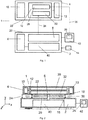
- Fig. 4 shows a side view of the weighing device 101 cut orthogonal to the z axis, wherein the application unit 110 is a magnetic stirrer 130 with a vertical orientation of the sending coil 116 and receiving coil 118 with respect to the top side 120 of the weighing unit 102 and the bottom side 122 of the secondary unit 104 according to another embodiment of the present invention.
- the top side 120 of the weighing unit 102 is orthogonally extended to form an orthogonal top side 121 as well as the bottom side 122 of the secondary unit 104 is orthogonally extended to form an orthogonal bottom side 123.
- the sending coil 116 is thus placed towards the orthogonal top side 121 of the weighing unit 102 and the receiving coil 118 is placed towards the orthogonal bottom side 123 of the secondary unit 104 thus making the orientation of the two coils vertical (along y-y' axis).
- the two coils can thus be placed on the back side 125 of the weighing unit 102 which is also the orthogonal top side 121 of the weighing unit 102 as seen in Fig. 4 to make sure the inductive force is not in the weighing direction.
- the secondary unit 104 is placed on the load receiver 106 of the weighing unit 102, power is inductively coupled from the sending coil 116 to the receiving coil 118 through the gap 124. This induced power then powers the magnetic stirrer 130 and the heating coil 145 that stirs and heats the sample in the beaker 144 respectively.
- the width of the gap 124 for applications like a magnetic stirrer 130 is fixed and mechanically designed to 5 mm.
- Fig. 5 shows a side view of the weighing device 201 cut orthogonal to the z axis, wherein the application unit 210 is a dosing pump 230 with a vertical orientation of the sending coil 216 and receiving coil 218 with respect to the top side 220 of the weighing unit 202 and the bottom side 222 of the secondary unit 204 respectively according to yet another embodiment of the present invention.
- the top side 220 of the weighing unit 202 is orthogonally extended to form an orthogonal top side 221 as well as the bottom side 222 of the secondary unit 204 is orthogonally extended to form an orthogonal bottom side 223.
- the sending coil 216 is thus placed towards the orthogonal top side 221 of the weighing unit 202 and the receiving coil 218 is placed towards the orthogonal bottom side 223 of the secondary unit 204 thus making the orientation of the two coils vertical (along y-y' axis).
- the two coils can thus be placed at the back side 225 of the weighing unit 201 as seen in Fig. 4 to make sure the inductive force is not in the weighing direction.
- the control unit 242 is connected to the weighing unit 202.
- the control unit 242 comprises a data transmitting unit 226 that is used for transmission of data to the secondary unit 204.
- the control unit 242 as shown in Fig. 5 is connected externally to the weighing unit 202.
- the control unit 242 however, can be placed within the weighing unit 202 as well.
- a back up-battery 213 is comprised within the secondary unit 204 to ensure sufficient power is supplied to the secondary unit 204 required to operate the application unit 210 in case sufficient power is not received by contactless power transmission.
Landscapes
- Engineering & Computer Science (AREA)
- Physics & Mathematics (AREA)
- General Physics & Mathematics (AREA)
- Power Engineering (AREA)
- Computer Networks & Wireless Communication (AREA)
- Life Sciences & Earth Sciences (AREA)
- Sustainable Development (AREA)
- Sustainable Energy (AREA)
- Induction Heating Cooking Devices (AREA)
- Near-Field Transmission Systems (AREA)
Claims (13)
- Wiegevorrichtung (1, 101, 201), umfassend eine Wiegeeinheit (2, 102, 202), eine Steuereinheit (42) und mindestens eine sekundäre Einheit (4, 104, 204), wobei die Wiegeeinheit (2, 102, 202) einen Lastempfänger (6, 106, 206) und eine Energieübertragungseinheit (8) umfasst, wobei die sekundäre Einheit (4, 104, 204) eine Anwendungseinheit (10, 110, 210) und eine Empfangseinheit (12) umfasst, wobei die Empfangseinheit (12) eine Datenempfangseinheit (28) und eine Energieempfangseinheit (32, 132, 232) umfasst, wobei die Steuereinheit (42, 142, 242) eine Datenübertragungseinheit (26, 126, 226) umfasst, wobei die sekundäre Einheit (4, 104, 204) auf dem Lastempfänger (6, 106, 206) der Wiegeeinheit (2, 102, 202) platziert ist, wobei ein Energiesignal (34), um die Anwendungseinheit (10, 110, 210) mit Energie zu versorgen, von der Energieübertragungseinheit (8) an die Leistungsempfangseinheit (32, 132, 232) der sekundären Einheit (4, 104, 204) kontaktlos übertragen wird und ein Steuersignal (36), um die Anwendungseinheit (10, 110, 210) der sekundären Einheit (4, 104, 204) zu steuern, von der Datenübertragungseinheit (26, 126, 226) der Steuereinheit (42, 142, 242) an die Datenempfangseinheit (28) der sekundären Einheit (4, 104, 204) kontaktlos übertragen wird und die Energieübertragungseinheit (8) aus mindestens einer Sendespule (16, 116, 126) besteht, wobei die Sendespule (16, 116, 126) in Richtung einer oberen Seite (20, 120, 220) der Wiegeeinheit (2, 102, 202), die einer unteren Seite (22, 122, 222) der sekundären Einheit (4, 104, 204) zugewandt ist, platziert ist und wobei die Empfangseinheit (12) ferner eine Energieempfangseinheit (32) umfasst, wobei die Energieempfangseinheit (32, 132, 232) mindestens eine Empfangsspule (18) umfasst, die in Richtung der unteren Seite (22, 122, 222) der sekundären Einheit (4, 104, 204) platziert ist und die obere Seite (20, 120, 220) der Wiegeeinheit (2, 102, 202) und die untere Seite (22, 122, 222) der sekundären Einheit (4, 104, 204), die die Sendespule (16, 116, 126) und die Empfangsspule (18, 118, 128) trägt, einander zugewandt sind, wenn die sekundäre Einheit (4, 104, 204) auf dem Lastempfänger (6, 106, 206) platziert ist, und die Sendespule (16, 116, 126) und die Empfangsspule (18, 118, 128) wiederum einander zugewandt sind, die derart ausgelegt sind, dass die Sendespule (16, 116, 126), wenn sie mit einer Standardenergiequelle verbunden ist, dazu imstande ist, Energie durch elektromagnetische Felder an die Empfangsspule (18, 118, 128) zu übertragen, wo die Energie in elektrische Energie zurückgewandelt werden kann.
- Wiegevorrichtung (1, 101, 201) nach Anspruch 1, wobei mindestens eine Sendespule (16, 116, 216) und mindestens eine Empfangsspule (18, 118, 218) horizontal in Bezug auf die obere Seite (20, 120, 220) der Wiegeeinheit (2, 102, 202) bzw. die untere Seite (22, 122, 22) der sekundären Einheit (4, 104, 204) ausgerichtet sind.
- Wiegevorrichtung (1, 101, 201) nach Anspruch 1, wobei mindestens eine Sendespule (16, 116, 216) und mindestens eine Empfangsspule (18, 118, 218) vertikal in Bezug auf die obere Seite (20) der Wiegeeinheit (2, 102, 202) bzw. die untere Seite (22, 122, 222) der sekundären Einheit (4, 104, 204) ausgerichtet sind.
- Wiegevorrichtung (1, 101, 201) nach Anspruch 2 oder 3, wobei die Breite eines Abstands (24, 124, 224) zwischen der Sendespule (16, 116, 216) und der Empfangsspule (18, 118, 218) in einem Bereich von 5 mm bis maximal 100 mm liegt.
- Wiegevorrichtung (1, 101, 201) nach Anspruch 1, wobei die Energieübertragung von der Wiegeeinheit (2, 102, 202) an die sekundäre Einheit (4, 104, 204) und/oder die Datenübertragung von der Steuereinheit (42, 142, 242) an die sekundäre Einheit (4, 104, 204) schnurlos oder kabellos ist.
- Wiegevorrichtung (1, 101, 201) nach Anspruch 1, wobei die sekundäre Einheit (4, 104, 204) kein externes Benutzersteuermittel aufweist.
- Wiegevorrichtung (1, 101, 201) nach Anspruch 1, wobei eine einzige Standardenergiequelle (14) und eine einzige Steuereinheit (42, 142, 242) verwendet werden, um sowohl die Wiegeeinheit (2) als auch die sekundäre Einheit (4, 104, 204) jeweils zu steuern.
- Wiegevorrichtung (1, 101, 201) nach Anspruch 1, wobei die sekundäre Einheit (4, 104, 204) ferner eine Reservebatterie (13) umfasst, um die sekundäre Einheit (4, 104, 204) mit Energie zu versorgen.
- Wiegevorrichtung (1, 101, 201) nach Anspruch 1, wobei die Anwendungseinheit (10, 110, 210) ein beliebiges von einem Magnetrührer oder einer Ausgabeeinheit oder einer Dosiereinheit sein kann, ohne darauf beschränkt zu sein.
- Verfahren zum kontaktlosen Versorgen der sekundären Einheit (4, 104, 204) mit Energie durch die Wiegeeinheit (2, 102, 202) nach Anspruch 1 bis 9, wobei das Energiesignal (34) in der Empfangsspule (18, 118, 218) durch die Sendespule (16, 116, 216) magnetisch induziert wird, wenn die Sendespule (16, 116, 216) durch eine Standardenergiequelle (14), die mit der Wiegeeinheit (2, 102, 202) verbunden ist, mit Energie versorgt wird.
- Verfahren zum kontaktlosen Steuern der sekundären Einheit (4, 104, 204) durch die Steuereinheit (42, 142, 242) nach Anspruch 10, wobei das Steuersignal (36) von der Datenübertragungseinheit (26, 126, 226) an die Datenempfangseinheit (28), die in der Empfangseinheit (12) enthalten ist, über ein beliebiges von den Verfahren, wie etwa Lichtkopplung, Fotokopplung, Infrarot-Übertragung, Bluetooth-Übertragung oder RFIDÜbertragung, ohne darauf beschränkt zu sein, übertragen wird.
- Verfahren zum kontaktlosen Versorgen der sekundären Einheit (4, 104, 204) mit Energie und Steuern dieser durch die Wiegeeinheit (2, 102, 202) bzw. die Steuereinheit (42, 142, 242) nach Anspruch 10 oder 11;
wobei das Energiesignal (34) und das Steuersignal (36) getrennt übertragen werden. - Verfahren zum kontaktlosen Versorgen der sekundären Einheit (4, 104, 204) mit Energie und Steuern dieser durch die Wiegeeinheit (2, 102, 202) bzw. die Steuereinheit (42) nach Anspruch 10 oder 11;
wobei das Energiesignal (34) und das Steuersignal (36) gleichzeitig übertragen werden.
Priority Applications (3)
| Application Number | Priority Date | Filing Date | Title |
|---|---|---|---|
| EP15167066.8A EP3093632B1 (de) | 2015-05-11 | 2015-05-11 | Wiegevorrichtung mit anwendungseinheiten |
| US15/136,249 US9989403B2 (en) | 2015-05-11 | 2016-04-22 | Weighing device providing contactless power to at least one secondary unit |
| CN201610304316.9A CN106153169B (zh) | 2015-05-11 | 2016-05-10 | 具有应用单元的称量设备 |
Applications Claiming Priority (1)
| Application Number | Priority Date | Filing Date | Title |
|---|---|---|---|
| EP15167066.8A EP3093632B1 (de) | 2015-05-11 | 2015-05-11 | Wiegevorrichtung mit anwendungseinheiten |
Publications (2)
| Publication Number | Publication Date |
|---|---|
| EP3093632A1 EP3093632A1 (de) | 2016-11-16 |
| EP3093632B1 true EP3093632B1 (de) | 2020-03-11 |
Family
ID=53175319
Family Applications (1)
| Application Number | Title | Priority Date | Filing Date |
|---|---|---|---|
| EP15167066.8A Active EP3093632B1 (de) | 2015-05-11 | 2015-05-11 | Wiegevorrichtung mit anwendungseinheiten |
Country Status (3)
| Country | Link |
|---|---|
| US (1) | US9989403B2 (de) |
| EP (1) | EP3093632B1 (de) |
| CN (1) | CN106153169B (de) |
Families Citing this family (3)
| Publication number | Priority date | Publication date | Assignee | Title |
|---|---|---|---|---|
| CN109916493A (zh) * | 2019-03-04 | 2019-06-21 | 太原学院 | 一种食品营养量化显示装置 |
| CN114127517B (zh) * | 2019-08-19 | 2024-05-24 | 株式会社岛津制作所 | 流动相余量计 |
| CN114358232B (zh) * | 2021-12-30 | 2023-09-12 | 华能国际电力股份有限公司上海石洞口第一电厂 | 一种工程成本管理方法、装置、设备及介质 |
Family Cites Families (16)
| Publication number | Priority date | Publication date | Assignee | Title |
|---|---|---|---|---|
| US4458539A (en) * | 1981-12-15 | 1984-07-10 | Baxter Travenol Laboratories, Inc. | Blood fractionation apparatus having collected volume display system |
| JP2594156B2 (ja) * | 1989-08-30 | 1997-03-26 | トヨタ自動車株式会社 | 流体圧式アクティブサスペンション |
| US5261742A (en) | 1993-02-23 | 1993-11-16 | Eastman Kodak Company | Air-powered apparatus and method for mixing a liquefied sample and weighing the sample |
| US5549382A (en) * | 1995-04-27 | 1996-08-27 | Correia, Ii; Bernard A. | Stirrer for food preparation |
| EP0929498B1 (de) * | 1996-09-06 | 2001-11-21 | Jean Pierre Solignac | Verfahren, vorrichtung und anlage zum ausgeben dosierten mengen flüssigkeit |
| DE10105535A1 (de) * | 2001-02-07 | 2002-08-08 | Mettler Toledo Albstadt Gmbh | Wägevorrichtung mit mehreren Funktionseinheiten |
| US6972384B2 (en) * | 2001-07-27 | 2005-12-06 | Mettler-Toledo, Inc. | Internet scale |
| GB0422787D0 (en) * | 2004-10-14 | 2004-11-17 | Ici Plc | A tinting machine system |
| AU2007302610B2 (en) | 2006-09-26 | 2014-04-10 | Autopour Pty Ltd | Dispensing apparatus and weighing process with control unit |
| EP1930702A1 (de) * | 2006-12-07 | 2008-06-11 | Mettler-Toledo AG | Dosiervorrichtung für pulver- oder pastenförmiges Dosiergut |
| US20100299074A1 (en) * | 2007-11-01 | 2010-11-25 | David Chang | Remote data collecting systems and methods |
| ES2367281B1 (es) | 2010-03-16 | 2012-09-04 | Electrodomésticos Taurus S.L. | Encimera de cocina con medios de accionamiento para cuchillas giratorias y conjunto de encimera de cocina y recipiente de cocina con cuchillas giratorias. |
| JP6144620B2 (ja) * | 2010-04-08 | 2017-06-07 | アクセス ビジネス グループ インターナショナル リミテッド ライアビリティ カンパニー | POS(pointofsale)誘導性システムと方法 |
| JP5687924B2 (ja) * | 2011-02-25 | 2015-03-25 | 株式会社イシダ | 計量印字装置 |
| FR2978064B1 (fr) * | 2011-07-18 | 2016-02-19 | Interlab | Procede et dispositif de distribution gravimetrique et en serie de solution. |
| GB2496678B (en) * | 2011-11-17 | 2015-07-15 | Bae Systems Plc | Protective material |
-
2015
- 2015-05-11 EP EP15167066.8A patent/EP3093632B1/de active Active
-
2016
- 2016-04-22 US US15/136,249 patent/US9989403B2/en active Active
- 2016-05-10 CN CN201610304316.9A patent/CN106153169B/zh active Active
Non-Patent Citations (1)
| Title |
|---|
| None * |
Also Published As
| Publication number | Publication date |
|---|---|
| CN106153169A (zh) | 2016-11-23 |
| CN106153169B (zh) | 2020-11-17 |
| US20160334268A1 (en) | 2016-11-17 |
| EP3093632A1 (de) | 2016-11-16 |
| US9989403B2 (en) | 2018-06-05 |
Similar Documents
| Publication | Publication Date | Title |
|---|---|---|
| JP5434330B2 (ja) | 電力受信装置、電力伝送システム、充電装置および電力伝送方法 | |
| US10530426B2 (en) | Wireless power transferring method and device therefor | |
| KR101423854B1 (ko) | 비접촉 급전 시스템 | |
| EP2937719B1 (de) | Fremdkörpererkennungsvorrichtung, drahtlose stromübertragungsvorrichtung und drahtloses stromübertragungssystem | |
| EP3093632B1 (de) | Wiegevorrichtung mit anwendungseinheiten | |
| EP2787596B1 (de) | Kabelloser Stromversorger und kabelloses Stromversorgungsverfahren | |
| KR102012972B1 (ko) | 무선 전력 송수신 장치 | |
| US20130200844A1 (en) | Wireless power charging method and apparatus | |
| JP5446452B2 (ja) | 電力供給装置、被電力供給装置、電力供給装置システム、位置決め制御方法 | |
| EP2713473A2 (de) | Kraftübertragende Vorrichtung mit Vorrichtungsdetektion und Leistungsübertragung | |
| US20120313447A1 (en) | Method of performing bidirectional communication between transmitter and receiver in wireless power transmission/reception system, the transmitter, and the receiver | |
| CN106716780B (zh) | 非接触供电设备、非接触受电设备以及具备它们的非接触电力传送系统 | |
| CN104137387A (zh) | 非接触供电系统、供电装置、受电装置及非接触供电系统的控制方法 | |
| US20160118810A1 (en) | Wireless power transmitter and receiver | |
| TW202042478A (zh) | 使用多個傳輸器及接收器的無線功率傳輸 | |
| JP2010088178A (ja) | 充電装置及び充電方法 | |
| JP2013115978A (ja) | 携帯機器及び給電台と携帯機器の給電方法 | |
| EP3118633A1 (de) | Planarer differenzieller stromabnehmer zur drahtlosen stromübertragung | |
| KR20140007712A (ko) | 무선 전력 송신기 및 그 제어 방법과, 무선 전력 송신기의 부하 값에 대한 온도 보상 방법 | |
| EP3588739B1 (de) | Stromversorgungsvorrichtung, elektronische vorrichtung, steuerungsverfahren und programm dafür sowie system zur drahtlosen stromübertragung | |
| US12587043B2 (en) | Power feed system | |
| EP3407461A1 (de) | System und verfahren zum drahtlosen laden eines positionssenders (beacon) und / oder sensorvorrichtung | |
| KR101386059B1 (ko) | 전자기 유도 및 자기 공진 방식을 이용한 무선 충전 케이스 및 무선 충전 방법 | |
| EP3242374B1 (de) | Vorrichtung zur drahtlosen stromübertragung und drahtloses ladesystem damit | |
| WO2018030062A1 (ja) | 給電機器および受電機器、ならびに、これらを備えた電力伝送システム |
Legal Events
| Date | Code | Title | Description |
|---|---|---|---|
| PUAI | Public reference made under article 153(3) epc to a published international application that has entered the european phase |
Free format text: ORIGINAL CODE: 0009012 |
|
| AK | Designated contracting states |
Kind code of ref document: A1 Designated state(s): AL AT BE BG CH CY CZ DE DK EE ES FI FR GB GR HR HU IE IS IT LI LT LU LV MC MK MT NL NO PL PT RO RS SE SI SK SM TR |
|
| AX | Request for extension of the european patent |
Extension state: BA ME |
|
| STAA | Information on the status of an ep patent application or granted ep patent |
Free format text: STATUS: REQUEST FOR EXAMINATION WAS MADE |
|
| 17P | Request for examination filed |
Effective date: 20170509 |
|
| RBV | Designated contracting states (corrected) |
Designated state(s): AL AT BE BG CH CY CZ DE DK EE ES FI FR GB GR HR HU IE IS IT LI LT LU LV MC MK MT NL NO PL PT RO RS SE SI SK SM TR |
|
| GRAP | Despatch of communication of intention to grant a patent |
Free format text: ORIGINAL CODE: EPIDOSNIGR1 |
|
| STAA | Information on the status of an ep patent application or granted ep patent |
Free format text: STATUS: GRANT OF PATENT IS INTENDED |
|
| INTG | Intention to grant announced |
Effective date: 20191004 |
|
| GRAS | Grant fee paid |
Free format text: ORIGINAL CODE: EPIDOSNIGR3 |
|
| GRAA | (expected) grant |
Free format text: ORIGINAL CODE: 0009210 |
|
| STAA | Information on the status of an ep patent application or granted ep patent |
Free format text: STATUS: THE PATENT HAS BEEN GRANTED |
|
| AK | Designated contracting states |
Kind code of ref document: B1 Designated state(s): AL AT BE BG CH CY CZ DE DK EE ES FI FR GB GR HR HU IE IS IT LI LT LU LV MC MK MT NL NO PL PT RO RS SE SI SK SM TR |
|
| REG | Reference to a national code |
Ref country code: GB Ref legal event code: FG4D |
|
| REG | Reference to a national code |
Ref country code: CH Ref legal event code: EP |
|
| REG | Reference to a national code |
Ref country code: AT Ref legal event code: REF Ref document number: 1243722 Country of ref document: AT Kind code of ref document: T Effective date: 20200315 |
|
| REG | Reference to a national code |
Ref country code: IE Ref legal event code: FG4D |
|
| REG | Reference to a national code |
Ref country code: DE Ref legal event code: R096 Ref document number: 602015048448 Country of ref document: DE |
|
| PG25 | Lapsed in a contracting state [announced via postgrant information from national office to epo] |
Ref country code: FI Free format text: LAPSE BECAUSE OF FAILURE TO SUBMIT A TRANSLATION OF THE DESCRIPTION OR TO PAY THE FEE WITHIN THE PRESCRIBED TIME-LIMIT Effective date: 20200311 Ref country code: NO Free format text: LAPSE BECAUSE OF FAILURE TO SUBMIT A TRANSLATION OF THE DESCRIPTION OR TO PAY THE FEE WITHIN THE PRESCRIBED TIME-LIMIT Effective date: 20200611 Ref country code: RS Free format text: LAPSE BECAUSE OF FAILURE TO SUBMIT A TRANSLATION OF THE DESCRIPTION OR TO PAY THE FEE WITHIN THE PRESCRIBED TIME-LIMIT Effective date: 20200311 |
|
| REG | Reference to a national code |
Ref country code: NL Ref legal event code: MP Effective date: 20200311 |
|
| PG25 | Lapsed in a contracting state [announced via postgrant information from national office to epo] |
Ref country code: HR Free format text: LAPSE BECAUSE OF FAILURE TO SUBMIT A TRANSLATION OF THE DESCRIPTION OR TO PAY THE FEE WITHIN THE PRESCRIBED TIME-LIMIT Effective date: 20200311 Ref country code: GR Free format text: LAPSE BECAUSE OF FAILURE TO SUBMIT A TRANSLATION OF THE DESCRIPTION OR TO PAY THE FEE WITHIN THE PRESCRIBED TIME-LIMIT Effective date: 20200612 Ref country code: SE Free format text: LAPSE BECAUSE OF FAILURE TO SUBMIT A TRANSLATION OF THE DESCRIPTION OR TO PAY THE FEE WITHIN THE PRESCRIBED TIME-LIMIT Effective date: 20200311 Ref country code: LV Free format text: LAPSE BECAUSE OF FAILURE TO SUBMIT A TRANSLATION OF THE DESCRIPTION OR TO PAY THE FEE WITHIN THE PRESCRIBED TIME-LIMIT Effective date: 20200311 Ref country code: BG Free format text: LAPSE BECAUSE OF FAILURE TO SUBMIT A TRANSLATION OF THE DESCRIPTION OR TO PAY THE FEE WITHIN THE PRESCRIBED TIME-LIMIT Effective date: 20200611 |
|
| REG | Reference to a national code |
Ref country code: LT Ref legal event code: MG4D |
|
| PG25 | Lapsed in a contracting state [announced via postgrant information from national office to epo] |
Ref country code: NL Free format text: LAPSE BECAUSE OF FAILURE TO SUBMIT A TRANSLATION OF THE DESCRIPTION OR TO PAY THE FEE WITHIN THE PRESCRIBED TIME-LIMIT Effective date: 20200311 |
|
| PG25 | Lapsed in a contracting state [announced via postgrant information from national office to epo] |
Ref country code: EE Free format text: LAPSE BECAUSE OF FAILURE TO SUBMIT A TRANSLATION OF THE DESCRIPTION OR TO PAY THE FEE WITHIN THE PRESCRIBED TIME-LIMIT Effective date: 20200311 Ref country code: LT Free format text: LAPSE BECAUSE OF FAILURE TO SUBMIT A TRANSLATION OF THE DESCRIPTION OR TO PAY THE FEE WITHIN THE PRESCRIBED TIME-LIMIT Effective date: 20200311 Ref country code: SM Free format text: LAPSE BECAUSE OF FAILURE TO SUBMIT A TRANSLATION OF THE DESCRIPTION OR TO PAY THE FEE WITHIN THE PRESCRIBED TIME-LIMIT Effective date: 20200311 Ref country code: RO Free format text: LAPSE BECAUSE OF FAILURE TO SUBMIT A TRANSLATION OF THE DESCRIPTION OR TO PAY THE FEE WITHIN THE PRESCRIBED TIME-LIMIT Effective date: 20200311 Ref country code: CZ Free format text: LAPSE BECAUSE OF FAILURE TO SUBMIT A TRANSLATION OF THE DESCRIPTION OR TO PAY THE FEE WITHIN THE PRESCRIBED TIME-LIMIT Effective date: 20200311 Ref country code: PT Free format text: LAPSE BECAUSE OF FAILURE TO SUBMIT A TRANSLATION OF THE DESCRIPTION OR TO PAY THE FEE WITHIN THE PRESCRIBED TIME-LIMIT Effective date: 20200805 Ref country code: SK Free format text: LAPSE BECAUSE OF FAILURE TO SUBMIT A TRANSLATION OF THE DESCRIPTION OR TO PAY THE FEE WITHIN THE PRESCRIBED TIME-LIMIT Effective date: 20200311 Ref country code: IS Free format text: LAPSE BECAUSE OF FAILURE TO SUBMIT A TRANSLATION OF THE DESCRIPTION OR TO PAY THE FEE WITHIN THE PRESCRIBED TIME-LIMIT Effective date: 20200711 |
|
| REG | Reference to a national code |
Ref country code: AT Ref legal event code: MK05 Ref document number: 1243722 Country of ref document: AT Kind code of ref document: T Effective date: 20200311 |
|
| REG | Reference to a national code |
Ref country code: DE Ref legal event code: R097 Ref document number: 602015048448 Country of ref document: DE |
|
| PLBE | No opposition filed within time limit |
Free format text: ORIGINAL CODE: 0009261 |
|
| STAA | Information on the status of an ep patent application or granted ep patent |
Free format text: STATUS: NO OPPOSITION FILED WITHIN TIME LIMIT |
|
| PG25 | Lapsed in a contracting state [announced via postgrant information from national office to epo] |
Ref country code: IT Free format text: LAPSE BECAUSE OF FAILURE TO SUBMIT A TRANSLATION OF THE DESCRIPTION OR TO PAY THE FEE WITHIN THE PRESCRIBED TIME-LIMIT Effective date: 20200311 Ref country code: ES Free format text: LAPSE BECAUSE OF FAILURE TO SUBMIT A TRANSLATION OF THE DESCRIPTION OR TO PAY THE FEE WITHIN THE PRESCRIBED TIME-LIMIT Effective date: 20200311 Ref country code: DK Free format text: LAPSE BECAUSE OF FAILURE TO SUBMIT A TRANSLATION OF THE DESCRIPTION OR TO PAY THE FEE WITHIN THE PRESCRIBED TIME-LIMIT Effective date: 20200311 Ref country code: AT Free format text: LAPSE BECAUSE OF FAILURE TO SUBMIT A TRANSLATION OF THE DESCRIPTION OR TO PAY THE FEE WITHIN THE PRESCRIBED TIME-LIMIT Effective date: 20200311 Ref country code: MC Free format text: LAPSE BECAUSE OF FAILURE TO SUBMIT A TRANSLATION OF THE DESCRIPTION OR TO PAY THE FEE WITHIN THE PRESCRIBED TIME-LIMIT Effective date: 20200311 |
|
| 26N | No opposition filed |
Effective date: 20201214 |
|
| PG25 | Lapsed in a contracting state [announced via postgrant information from national office to epo] |
Ref country code: PL Free format text: LAPSE BECAUSE OF FAILURE TO SUBMIT A TRANSLATION OF THE DESCRIPTION OR TO PAY THE FEE WITHIN THE PRESCRIBED TIME-LIMIT Effective date: 20200311 Ref country code: SI Free format text: LAPSE BECAUSE OF FAILURE TO SUBMIT A TRANSLATION OF THE DESCRIPTION OR TO PAY THE FEE WITHIN THE PRESCRIBED TIME-LIMIT Effective date: 20200311 |
|
| REG | Reference to a national code |
Ref country code: BE Ref legal event code: MM Effective date: 20200531 |
|
| PG25 | Lapsed in a contracting state [announced via postgrant information from national office to epo] |
Ref country code: LU Free format text: LAPSE BECAUSE OF NON-PAYMENT OF DUE FEES Effective date: 20200511 |
|
| PG25 | Lapsed in a contracting state [announced via postgrant information from national office to epo] |
Ref country code: IE Free format text: LAPSE BECAUSE OF NON-PAYMENT OF DUE FEES Effective date: 20200511 |
|
| PG25 | Lapsed in a contracting state [announced via postgrant information from national office to epo] |
Ref country code: BE Free format text: LAPSE BECAUSE OF NON-PAYMENT OF DUE FEES Effective date: 20200531 |
|
| PG25 | Lapsed in a contracting state [announced via postgrant information from national office to epo] |
Ref country code: TR Free format text: LAPSE BECAUSE OF FAILURE TO SUBMIT A TRANSLATION OF THE DESCRIPTION OR TO PAY THE FEE WITHIN THE PRESCRIBED TIME-LIMIT Effective date: 20200311 Ref country code: MT Free format text: LAPSE BECAUSE OF FAILURE TO SUBMIT A TRANSLATION OF THE DESCRIPTION OR TO PAY THE FEE WITHIN THE PRESCRIBED TIME-LIMIT Effective date: 20200311 Ref country code: CY Free format text: LAPSE BECAUSE OF FAILURE TO SUBMIT A TRANSLATION OF THE DESCRIPTION OR TO PAY THE FEE WITHIN THE PRESCRIBED TIME-LIMIT Effective date: 20200311 |
|
| PG25 | Lapsed in a contracting state [announced via postgrant information from national office to epo] |
Ref country code: MK Free format text: LAPSE BECAUSE OF FAILURE TO SUBMIT A TRANSLATION OF THE DESCRIPTION OR TO PAY THE FEE WITHIN THE PRESCRIBED TIME-LIMIT Effective date: 20200311 Ref country code: AL Free format text: LAPSE BECAUSE OF FAILURE TO SUBMIT A TRANSLATION OF THE DESCRIPTION OR TO PAY THE FEE WITHIN THE PRESCRIBED TIME-LIMIT Effective date: 20200311 |
|
| PGFP | Annual fee paid to national office [announced via postgrant information from national office to epo] |
Ref country code: DE Payment date: 20250528 Year of fee payment: 11 |
|
| PGFP | Annual fee paid to national office [announced via postgrant information from national office to epo] |
Ref country code: FR Payment date: 20250526 Year of fee payment: 11 |
|
| PGFP | Annual fee paid to national office [announced via postgrant information from national office to epo] |
Ref country code: CH Payment date: 20250601 Year of fee payment: 11 |
|
| PGFP | Annual fee paid to national office [announced via postgrant information from national office to epo] |
Ref country code: GB Payment date: 20260304 Year of fee payment: 12 |