EP3093679A1 - Stator de mas avec dispositif d'aspiration - Google Patents
Stator de mas avec dispositif d'aspiration Download PDFInfo
- Publication number
- EP3093679A1 EP3093679A1 EP16169076.3A EP16169076A EP3093679A1 EP 3093679 A1 EP3093679 A1 EP 3093679A1 EP 16169076 A EP16169076 A EP 16169076A EP 3093679 A1 EP3093679 A1 EP 3093679A1
- Authority
- EP
- European Patent Office
- Prior art keywords
- mas
- stator
- rotor
- gas
- bearing
- Prior art date
- Legal status (The legal status is an assumption and is not a legal conclusion. Google has not performed a legal analysis and makes no representation as to the accuracy of the status listed.)
- Granted
Links
Images




Classifications
-
- G—PHYSICS
- G01—MEASURING; TESTING
- G01R—MEASURING ELECTRIC VARIABLES; MEASURING MAGNETIC VARIABLES
- G01R33/00—Arrangements or instruments for measuring magnetic variables
- G01R33/20—Arrangements or instruments for measuring magnetic variables involving magnetic resonance
- G01R33/28—Details of apparatus provided for in groups G01R33/44 - G01R33/64
- G01R33/30—Sample handling arrangements, e.g. sample cells, spinning mechanisms
- G01R33/307—Sample handling arrangements, e.g. sample cells, spinning mechanisms specially adapted for moving the sample relative to the MR system, e.g. spinning mechanisms, flow cells or means for positioning the sample inside a spectrometer
-
- G—PHYSICS
- G01—MEASURING; TESTING
- G01R—MEASURING ELECTRIC VARIABLES; MEASURING MAGNETIC VARIABLES
- G01R33/00—Arrangements or instruments for measuring magnetic variables
- G01R33/20—Arrangements or instruments for measuring magnetic variables involving magnetic resonance
- G01R33/28—Details of apparatus provided for in groups G01R33/44 - G01R33/64
- G01R33/30—Sample handling arrangements, e.g. sample cells, spinning mechanisms
- G01R33/302—Miniaturized sample handling arrangements for sampling small quantities, e.g. flow-through microfluidic NMR chips
-
- G—PHYSICS
- G01—MEASURING; TESTING
- G01R—MEASURING ELECTRIC VARIABLES; MEASURING MAGNETIC VARIABLES
- G01R33/00—Arrangements or instruments for measuring magnetic variables
- G01R33/20—Arrangements or instruments for measuring magnetic variables involving magnetic resonance
- G01R33/44—Arrangements or instruments for measuring magnetic variables involving magnetic resonance using nuclear magnetic resonance [NMR]
Definitions
- NMR nuclear magnetic resonance
- MAS Magic Angle-Spinning
- Such an NMR MAS probe is known from DE 10 2013 201 110 B3 ,
- Nuclear magnetic resonance (NMR) spectroscopy is a method of instrumental analysis, with which in particular the chemical composition of test samples can be determined.
- MAS rotors are cylindrical tubes closed with one or two caps, the upper one being provided with wing elements ("paddle wheels").
- the MAS rotor is placed in a MAS stator and, with gas pressure, the MAS rotor is driven by the wing elements for rotation.
- the totality of MAS rotor and MAS stator is called MAS turbine.
- the MAS turbine is placed in a NMR MAS probe.
- the probe has a cylindrical shielding tube (also called “tube” for short) and usually a foot box.
- the probe head is typically inserted with its shielding tube from below into the vertical room temperature bore of a superconducting magnet, positioned, and held with hooks, posts, screws or the like.
- the MAS turbine is then located exactly in the magnetic center of the magnet.
- a MAS rotor can be conveyed into the MAS stator of the probe head mounted in the magnet by means of gas pressure, and also a MAS rotor can be conveyed out of the MAS stator upwards out of the probe head.
- a probe head with a foot box and attached to the foot box and protruding from this pipe proposed, being arranged in the region of the foot box end of the tube within the tube of the MAS stator for receiving a MAS rotor, and wherein a transport line for pneumatic transfer a MAS rotor within the transport line, which runs inside the tube from the foot box to the MAS stator.
- the front bearing not as in a generic type probe head of the type defined a closable by means of a closure opening for introducing a MAS rotor in the space between bottom bearing and front bearing, so that a rotor change in the closed probe head is not possible , Especially with MAS rotors with diameters ⁇ 1.9mm, a shutter on both sides is required to stabilize the rotation.
- DE 10 2013 201 110 B3 proposed to provide a transport line for transferring a MAS rotor NMR MAS probe head with which the rotor can be transferred to the stator.
- the stator includes an additional shutter on the head side of the rotor to stabilize the rotation.
- MAS rotors with a diameter of less than 2.5 mm is to be expected problems because the Bernoulli force of the bottom bearing is not sufficient, at least not sufficiently reliable to keep the rotor in position.
- the DE 11 2005 002 582 T5 discloses an axial Bernoulli gas bearing for a gas driven NMR MAS sample rotor in which a low rotational component influx flows inwardly over a conically shaped rotor end. Between this and a conical stator bearing surface, a conical flow area is formed.
- the stator presented here is particularly suitable for automated rotor replacement. It will be in the DE 11 2005 002 582 T5 not described, whether it is particularly suitable for rotors with small diameters. Also, a gas discharge from the Bernoulli camp away is not disclosed.
- the MAS rotor is kept gas-stored in the stator during the NMR measurement in order to reduce the friction losses and thus to be able to achieve the high rotational speeds.
- the latter generates by high gas velocity in the radial direction, a high dynamic pressure with simultaneous lowering of the static pressure, which generates a force in the axial direction, namely the Bernoulli force that holds the rotor in the stator and levitate it on an air cushion.
- this only applies to MAS rotors with a diameter larger than 2.5 mm.
- the present invention is based on the object to provide an NMR MAS probe head of the type defined with stabilized rotation available, which manages without the aforementioned closure means.
- the system should be automatable, i. allow a sample exchange without the need for a mechanical seal at the top of the stator / without removing the head from the magnet.
- a MAS stator of the aforementioned type which is characterized in that in a space below the radial bearing, a suction device for extracting the gas introduced from the gas supply means is provided, which is designed so that they are in the Space below the radial bearing in measuring mode can generate a negative pressure relative to the atmosphere surrounding the MAS stator.
- a stator for NMR-MAS spectroscopy which has no closure at the head of the stator, and thus the stator can be fed easily and easily automatable with the rotor.
- the axial force directed towards the bottom bearing rises on the rotor.
- the technical effect that results from the suction is, inter alia, that the Significantly improve rotational properties of the rotors.
- smaller rotors 2.5mm, 1.9mm, 1.3mm, 0.7mm down to 0.2mm
- a sample change is thus possible without removing the closure.
- the holding force should be sufficient by the Bernoulli effect on the axial bottom bearing even with small rotors.
- dynamic effects such as e.g. Imbalances, transient processes at startup or spurious frequencies. These effects affect the distance of the rotor from the ground bearing.
- the parasitic effects are compensated for larger rotors by the larger mass of the rotors, i. they are easier to get into the balance of power of the camp.
- the rotor is centered by means of at least one radial bearing.
- the radial bearing comprises a plurality of gas nozzles, usually 5 to 8 pieces, which direct a gas flow from the outside in the radial direction of the rotor.
- the gas nozzles usually have a diameter of 150-300 ⁇ m.
- the system comprises a bottom bearing, which directs a gas flow in the axial direction on the planar rotor end or the introduced into the rotor end planar bottom cap.
- the rotor is thus prevented from lying on the ground surface.
- the outgoing gas causes the Bernoulli force to hold the rotor in position.
- the MAS stator is for receiving a MAS rotor having a diameter of 0.2mm to 2.5mm, preferably 0.7mm to 1 , 9mm, designed. Until now, MAS rotors in this size range required a closure at the head end of the MAS stator.
- the suction device comprises a gas line for sucking the gas introduced by the gas supply device with a cross section of 0.2 mm 2 to 100 mm 2 , preferably 1.5 mm 2 to 10 mm 2 , having. This is usually sufficient for the volume of extracted gas stream.
- the suction device is designed so that it can be acted upon during measurement operation with a negative pressure with respect to the atmosphere surrounding the MAS stator from -0.1 bar to -1 bar.
- the under-pressure is -0.2bar to -0.4bar, whereby, for example, with 1.3mm rotors, a sufficiently high holding force is achieved for stable operation without undesirable ejection.
- the advantage of low suction pressure is the low power required to operate the exhaust. For larger rotors, after all, there is still a particularly smooth and stable rotation behavior.
- Embodiments of the invention are also preferred in which a pneumatic sample exchange system with a transport line for supplying and discharging a MAS rotor to the MAS stator is provided, which likewise contributes to the automation of the measurement preparations.
- a pneumatic sample exchange system with a transport line for supplying and discharging a MAS rotor to the MAS stator is provided, which likewise contributes to the automation of the measurement preparations.
- One advantage of the present invention is, inter alia, that the sample exchange system according to DE 10 2008 054 152 B3 in the same way for rotors with a diameter of 0.2mm to 2.5mm can be used. So far this only with the use of a closure device according to the cited above DE 10 2013 201 110 B3 possible.
- a further preferred embodiment provides that the probe head is formed in the region of the tube as a Dewar vessel.
- the tube is thus double-walled, formed with a vacuum lying between the walls; this facilitates the tempering or cooling of the sample in the probe for the NMR measurement. Due to the closed training there are no unwanted heat conduction bridges.
- the nozzle in the bottom bearing has an internal diameter of between 25 ⁇ m and 500 ⁇ m, preferably between 80 ⁇ m and 200 ⁇ m.
- Another class of particularly simple and compact embodiments of the invention is characterized in that the device for gas supply comprises only a single nozzle in the bottom storage, with the in operation both the gas supply for the gas storage and the gas supply to the pneumatic drive for Rotation of the MAS rotor takes place together.
- a further device for supplying gas to the MAS rotor is provided, with which the measuring substance can be maintained at a predeterminable operating temperature during measuring operation.
- the MAS stator is rotatably mounted for setting the MAS angle. Due to the rotatability of the stator in the probe head, the entry and exit of the MAS rotor can be further facilitated in a limited space; tight curves are avoided. Due to the rotatability of the stator can be used to inject and remove the angle of the Stator bearing axis relative to the longitudinal direction of the tube (which regularly corresponds at least to a good approximation of the direction of the static magnetic field in the NMR magnet) are reduced compared to the magic angle.
- a method for operating a probe head with MAS stator of the type described above which is characterized in that after positioning of the MAS rotor in the MAS stator first the suction device is approached before the bottom bearing with Compressed gas is charged, so that the MAS rotor remains in the stator and can rotate without vibration.
- the MAS rotor with the measuring substance is removed from its measuring position within the MAS stator by switching off the vacuum generation at the suction device, while, however, the device for gas supply to the bottom bearing Compressed gas is charged so that an overpressure is built up in the space below the radial bearing, through which the MAS rotor is thrown out of its measuring position.
- a MAS rotor with a diameter of 0.2mm to 2.5mm, preferably from 0.7mm to 1.9mm.
- the invention relates to a novel embodiment of the bottom bearing of a MAS stator for a MAS-NMR probe head, in which no closure is provided at the top end of the MAS stator, so that a particularly simple sample change is made possible. Instead, the space below the radial bearing is extracted by means of a special device.
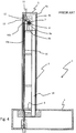
- the tube 2 here has a double wall (with an outer wall 4a and an inner wall 4b ), between which a vacuum is arranged, so that the tube 2 at the same time as a Dewar vessel for thermal insulation of the (usually room temperature ) Environment is formed.
- a coolant such as liquid nitrogen
- Alternative (or additional) can also the transport gas flow in the transport line 10 and / or other functional gas streams (see below) are cooled, whereby (with good insulation of the tube 2) also a good cooling in the interior of the tube 2 can be achieved.
- At least one wall 4a, 4b of the tube 2 is made of a good electrical conductivity, but non-ferromagnetic metal (such as copper).
- the metallic tube wall causes a shielding of the tube interior against external alternating electromagnetic fields; therefore, the tube 2 is also called a shielding tube.
- the tube 2 is at its in Fig. 4 upper, the foot box 3 facing away, free end 5 formed closed, in particular, no bushings for gas or transport lines are provided. Accesses to the interior of the pipe, such as for electrical, gas and transport lines are provided exclusively in the area of the footbox near end 6 of the tube 2.
- the tube 2 contains in the region of its free end 5 a MAS stator 7.
- the stator 7 may be a MAS rotor (not shown in the FIGS. 1 . 4 and 7 ) at the magic angle (relative to the longitudinal extent of the tube 2, which is aligned parallel to the static magnetic field in the measuring operation) and store for rotation about the axis of the rotor.
- the stator 7 further has a first, lower radial bearing 9a near the bottom bearing 8 and a second, opposite, upper radial bearing 9b, in each of which an opening for the passage of the rotor is formed.
- the bottom bearing 8 and the first radial bearing 9 a face the foot box 3, and the second radial bearing 9 b faces away from the foot box 3.
- the center between the first and second radial bearings 9a, 9b is the magnetic center of the magnet arrangement in the NMR measurement.
- the stator 7 has gas nozzles, not shown, with which an inserted rotor can be blown and rotated.
- a transport line 10 for MAS rotors Inside the tube 2 continues to run a transport line 10 for MAS rotors.
- a first section 10a of the transport line 10 leads from the end near the footwell 6 of the tube 2 past the stator 7 to a switch device 11.
- a second section 10b of the transport line 10 leads from the switch device 11 to the stator 7.
- the switch device 11 comprises a blind bore section 13 and a branch 12 of the transport line 10 (see also Fig. 4 ).
- the transport conduit 10 is generally formed by flexible hoses and / or rigid tubes, and may also include curved sections (curves) in addition to straight sections, taking into account the size of the MAS rotors and the play of the rotors in the transport conduit 10.
- the rotors are pneumatically conveyed by gas pressure and / or gravity in the transport line 10.
- a robust frame 14 is further formed, on which the stator 7 and various electronic components (not shown separately) for an NMR measurement are arranged on a measuring sample arranged in the stator.
- the first portion 10a of the transport line 10 is formed here as a rigid tube, whereby the frame 14 reaches an improved stability. Some electronic components are directly attached to the section 10a (not shown separately).
- FIG. 5 illustrates the introduction of a MAS rotor 21 a, 21 b, 21 c in the MAS stator 7 of the probe head according to the FIGS. 1 or 7 in detail.
- the representations 21 a, 21 b, 21 c of the rotor affect various stages during insertion.
- a rotor 21a is first conveyed through the first portion 10a of the transport line upwards in the direction of switch device 11 by a gas flow.
- the cap 22 of the rotor 21 a points upward.
- wing elements are formed (not visible in Fig. 6 ).
- the rotor 21 a is pressed by the attacking gas flow from the bottom up into the blind bore portion 13.
- the gas stream then flows from the portion 10a through the branch 12 into the second portion 10b of the transport line to the stator 7.
- This gas stream then blows the rotor 21b towards the second portion 10b, i. the rotor 21 b pivots with its lower bottom end to the right and drops again.
- the rotor 21c is urged by the gas flow in the direction of the MAS stator 7 to the bottom right into the second section 10b and into the stator 7.
- the transport direction includes a reversal (turning maneuver).
- a reverse gas flow is applied for discharging a rotor 21 c from the stator 7.
- This pushes the rotor 21 c first from the stator 7 through the second portion 10 b in the blind bore portion 13.
- a gas flow from the second portion 10 b of the transport line through the branch 12 in the first portion 10 a of the transport line.
- This pulls the rotor 21 b in the direction of the first portion 10 a and finally into this, so that the rotor 21 a is conveyed back through the first portion 10 a of the transport line to the foot box.
- the transport direction includes a reversal (turning maneuver).
- the tube can have a small inner diameter ID, so that even in tight room temperature bores of magnet arrangements, an inventive probe head can be introduced.
- a slight curve of 54.7 ° in the region of the second portion 10b of the transport line is set up.
- the outer diameter of the tube can be easily limited according to the invention for standard room temperature holes to 40mm or 73mm.
- FIG. 6 Figure 4 shows a modified NMR apparatus 51 comprising a superconducting magnet assembly 52 (here not shown, solenoid-shaped superconducting solenoids) having a vertical room temperature bore 53.
- the magnet assembly 52 rests on sturdy supports 54.
- an NMR according to the invention from below -MAS probe head 1 (cf. Fig. 4 ) introduced.
- the largest part of the tube 2 of the probe head 1 lies within the room temperature bore 53, while the foot box 3 of the probe head 1 is arranged outside the room temperature bore 53 below the magnet arrangement 52.
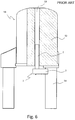
- FIG. 7 shows a generic MAS stator according to the prior art, which has the above-defined just not the specific features according to the invention and a manually als- and unscrewable front bearing 96a for introducing or removing the rotor space within of the MAS stator 7 between bottom bearing 8 and front bearing 96a.
- the opening 96b is always closed so that automated loading and unloading with the rotor is not possible. Rather, it must always be introduced or removed by hand.
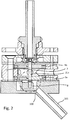
- FIGS. 1 to 3 illustrated MAS stator 7 characterized in that in a space below the radial bearing 9a, a suction device 100 is provided for extracting the gas introduced from the gas supply means, which is designed so that they in the space below the radial bearing 9a in measuring operation, a negative pressure relative to the atmosphere surrounding the MAS stator 7.
- the MAS stator 7 for receiving a MAS rotor 21 c is designed with a diameter of 0.2mm to 2.5mm, preferably from 0.7mm to 1.9mm.
- the suction device 100 has a gas line 101 , which serves for the extraction of the gas introduced by the device for gas supply and a cross section of 0.2mm 2 to 100mm 2 , preferably from 1.5mm 2 to 10mm 2 , will have.
- Both the radial bearings 9a, 9b and the bottom bearing 8 are preferably charged via a common compressed gas line. Alternatively, multiple lines can be used.
- the Einstrahldruck is 0 to 5bar relative to the ambient pressure.
- another gas stream is directed to the rotor blades at the top of the rotor.
- this current is directed tangentially to the rotor blades, so that they can be made to rotate.
- the drive gas flow can go up to 5bar relative to the ambient pressure.
- the system also includes a suction line at the bottom end of the stator.
- the function of this line is to remove the injected gas at reduced relative pressure (about -0.1 to -1 bar). Essentially, the gas flow of the Bernoulli bottom bearing is sucked in, but also portions of the gas flow of the lower radial bearing are removed downwards. As a result, the gas flow in the vicinity of the bottom bearing is changed, resulting in a greater holding force in the bottom bearing.
- a further gas stream can be supplied to the rotor, which serves for targeted temperature control of the measurement sample.
- the stator comprises two radial bearings, this leads to a further stabilization of the rotor.
- the distance from the radial bearing to the rotor is 5 to 50 ⁇ m, preferably 10 to 30 ⁇ m.
- the distance from the bottom bearing to the rotor is preferably 5 to 25 ⁇ m.
- the suction hose should have an inside diameter of at least 0.5mm.
Landscapes
- Physics & Mathematics (AREA)
- Condensed Matter Physics & Semiconductors (AREA)
- General Physics & Mathematics (AREA)
- Chemical & Material Sciences (AREA)
- Dispersion Chemistry (AREA)
- High Energy & Nuclear Physics (AREA)
- Magnetic Bearings And Hydrostatic Bearings (AREA)
Applications Claiming Priority (1)
| Application Number | Priority Date | Filing Date | Title |
|---|---|---|---|
| DE102015208850.2A DE102015208850B4 (de) | 2015-05-13 | 2015-05-13 | MAS-Stator mit Absaugvorrichtung |
Publications (2)
| Publication Number | Publication Date |
|---|---|
| EP3093679A1 true EP3093679A1 (fr) | 2016-11-16 |
| EP3093679B1 EP3093679B1 (fr) | 2017-10-25 |
Family
ID=55967123
Family Applications (1)
| Application Number | Title | Priority Date | Filing Date |
|---|---|---|---|
| EP16169076.3A Active EP3093679B1 (fr) | 2015-05-13 | 2016-05-11 | Stator pour ram avec dispositif d'aspiration |
Country Status (4)
| Country | Link |
|---|---|
| US (1) | US10132881B2 (fr) |
| EP (1) | EP3093679B1 (fr) |
| JP (1) | JP6445484B2 (fr) |
| DE (1) | DE102015208850B4 (fr) |
Cited By (3)
| Publication number | Priority date | Publication date | Assignee | Title |
|---|---|---|---|---|
| DE102018202002B3 (de) | 2018-02-08 | 2019-04-25 | Bruker Biospin Gmbh | NMR-MAS-Probenkopf mit verschwenkbarem Stator |
| US10830845B2 (en) * | 2017-11-20 | 2020-11-10 | Bruker Switzerland Ag | MAS-NMR rotor system with improved space utilization |
| CN114764078A (zh) * | 2021-01-14 | 2022-07-19 | 中国科学院宁波材料技术与工程研究所 | 一种高温核磁共振探头和高温核磁共振装置 |
Families Citing this family (4)
| Publication number | Priority date | Publication date | Assignee | Title |
|---|---|---|---|---|
| DE102016218772A1 (de) * | 2016-09-28 | 2018-03-29 | Bruker Biospin Gmbh | Verbesserte Temperierung eines NMR-MAS-Rotors |
| DE102017220707B4 (de) * | 2017-11-20 | 2019-05-29 | Bruker Biospin Ag | MAS-NMR-Probenkopfanordnung mit auswechselbarem Stator |
| DE102019202001B3 (de) * | 2019-02-14 | 2020-06-25 | Bruker Biospin Gmbh | MAS-Probenkopf mit thermisch isolierter Probenkammer |
| JP7636376B2 (ja) | 2022-08-26 | 2025-02-26 | 日本電子株式会社 | 試料管移送装置 |
Citations (6)
| Publication number | Priority date | Publication date | Assignee | Title |
|---|---|---|---|---|
| EP0089097A2 (fr) * | 1979-05-29 | 1983-09-21 | Varian Associates, Inc. | Dispositif pour tourner un échantillon pour sondes à résonance magnétique nucléaire |
| DE3818039A1 (de) | 1988-05-27 | 1989-11-30 | Bruker Analytische Messtechnik | Nmr-spektrometer mit einem probenwechsler |
| DE112005002582T5 (de) | 2004-10-20 | 2007-09-06 | Doty Scientific, Inc. | Bernoulli-Lager mit Gaszufluss für NMR MAS |
| US20100026302A1 (en) * | 2006-12-08 | 2010-02-04 | Doty Scientific, Inc. | NMR CryoMAS probe for high-field wide-bore magnets |
| DE102008054152B3 (de) | 2008-10-31 | 2010-06-10 | Bruker Biospin Gmbh | NMR-MAS-Probenkopf mit integrierter Transportleitung für einen MAS-Rotor |
| DE102013201110B3 (de) | 2013-01-24 | 2014-04-10 | Bruker Biospin Gmbh | NMR-MAS-Probenkopf mit integrierter Transportleitung für einen MAS-Rotor |
Family Cites Families (3)
| Publication number | Priority date | Publication date | Assignee | Title |
|---|---|---|---|---|
| US4446430A (en) * | 1981-08-31 | 1984-05-01 | Monsanto Company | Sample spinner for nuclear magnetic resonance spectrometer |
| JP6016373B2 (ja) * | 2012-02-14 | 2016-10-26 | 国立研究開発法人物質・材料研究機構 | Nmrプローブ装置 |
| US9194920B2 (en) * | 2012-10-10 | 2015-11-24 | Batelle Memorial Institute | Magic angle spinning nuclear magnetic resonance apparatus and process for high-resolution in situ investigations |
-
2015
- 2015-05-13 DE DE102015208850.2A patent/DE102015208850B4/de not_active Expired - Fee Related
-
2016
- 2016-05-11 EP EP16169076.3A patent/EP3093679B1/fr active Active
- 2016-05-11 JP JP2016095305A patent/JP6445484B2/ja active Active
- 2016-05-12 US US15/152,573 patent/US10132881B2/en active Active
Patent Citations (7)
| Publication number | Priority date | Publication date | Assignee | Title |
|---|---|---|---|---|
| EP0089097A2 (fr) * | 1979-05-29 | 1983-09-21 | Varian Associates, Inc. | Dispositif pour tourner un échantillon pour sondes à résonance magnétique nucléaire |
| DE3818039A1 (de) | 1988-05-27 | 1989-11-30 | Bruker Analytische Messtechnik | Nmr-spektrometer mit einem probenwechsler |
| DE112005002582T5 (de) | 2004-10-20 | 2007-09-06 | Doty Scientific, Inc. | Bernoulli-Lager mit Gaszufluss für NMR MAS |
| US20100026302A1 (en) * | 2006-12-08 | 2010-02-04 | Doty Scientific, Inc. | NMR CryoMAS probe for high-field wide-bore magnets |
| US7915893B2 (en) | 2006-12-08 | 2011-03-29 | Doty Scientific, Inc. | NMR CryoMAS probe for high-field wide-bore magnets |
| DE102008054152B3 (de) | 2008-10-31 | 2010-06-10 | Bruker Biospin Gmbh | NMR-MAS-Probenkopf mit integrierter Transportleitung für einen MAS-Rotor |
| DE102013201110B3 (de) | 2013-01-24 | 2014-04-10 | Bruker Biospin Gmbh | NMR-MAS-Probenkopf mit integrierter Transportleitung für einen MAS-Rotor |
Non-Patent Citations (1)
| Title |
|---|
| SID SHEVGOOR ET AL.: "Development of a C?oMASTM HR-MAS-MAG NMR Probe for High-field WB Magnets", DOTY SCIENTIFIC, COLUMBIA, SC, USA, 2005, Retrieved from the Internet <URL:http://www.dotvnmr.com/PDF/CrvoMAS ENC05.pdf> |
Cited By (3)
| Publication number | Priority date | Publication date | Assignee | Title |
|---|---|---|---|---|
| US10830845B2 (en) * | 2017-11-20 | 2020-11-10 | Bruker Switzerland Ag | MAS-NMR rotor system with improved space utilization |
| DE102018202002B3 (de) | 2018-02-08 | 2019-04-25 | Bruker Biospin Gmbh | NMR-MAS-Probenkopf mit verschwenkbarem Stator |
| CN114764078A (zh) * | 2021-01-14 | 2022-07-19 | 中国科学院宁波材料技术与工程研究所 | 一种高温核磁共振探头和高温核磁共振装置 |
Also Published As
| Publication number | Publication date |
|---|---|
| EP3093679B1 (fr) | 2017-10-25 |
| DE102015208850B4 (de) | 2018-12-20 |
| DE102015208850A1 (de) | 2016-11-17 |
| US20160334478A1 (en) | 2016-11-17 |
| JP2017009579A (ja) | 2017-01-12 |
| JP6445484B2 (ja) | 2018-12-26 |
| US10132881B2 (en) | 2018-11-20 |
Similar Documents
| Publication | Publication Date | Title |
|---|---|---|
| EP3093679B1 (fr) | Stator pour ram avec dispositif d'aspiration | |
| DE102008054152B3 (de) | NMR-MAS-Probenkopf mit integrierter Transportleitung für einen MAS-Rotor | |
| DE102013201110B3 (de) | NMR-MAS-Probenkopf mit integrierter Transportleitung für einen MAS-Rotor | |
| EP3301467B1 (fr) | Tempérage amélioré d'un rotor rmn mas | |
| DE102014201076B3 (de) | Transportbehälter für einen NMR MAS-Rotor | |
| EP1818679A1 (fr) | Support d'échantillon destiné à la fixation et au transport d'une cupule d'échantillon à l'intérieur d'un dispositif RMN tout comme dispositif d'implantation automatique pour l'échange automatisé de cupules d'échantillons RMN et procédé de fonctionnement | |
| EP3715893B1 (fr) | Spectromètre rmn pourvu de système de changement rapide pour échantillons | |
| EP3171191B1 (fr) | Sonde à angle réglable d'un appareil rmn avec rotation a l'angle magique | |
| EP3553545B1 (fr) | Dispositif de transport pour échantillons de mesure rmn tempérés pourvu de système à tube double | |
| DE19854785C1 (de) | Zellenradschleuse mit Ausziehvorrichtung | |
| EP1126269B1 (fr) | Dispositif pour l'analyse mécanique dynamique d'échantillons | |
| DE202013007878U1 (de) | Vorrichtung zur Luftkühlung eines Schrumpfspannfutters | |
| EP3486670B1 (fr) | Système de rotor rmn mas à utilisation de l'espace améliorée | |
| EP3696559A1 (fr) | Tête de sonde mas à chambre à échantillons thermiquement isolée | |
| EP3486671B1 (fr) | Dispositif de tête d'échantillon rmn pour mas à stator interchangeable | |
| EP2843436B1 (fr) | Spectromètre NMR doté d'un changeur d'échantillons avantageux, ergonomique | |
| EP3889630B1 (fr) | Rotor rmn magnétiquement compensé et procédé de conception et de fabrication | |
| EP2150829A1 (fr) | Agencement d'aimants destinés à créer un champ magnétique permanent homogène pouvant être utilisé en résonance magnétique nucléaire | |
| DE102007005913A1 (de) | Vorrichtung zur Ultraschallbearbeitung sowie ein für den Einsatz in der Vorrichtung geeignetes System aus Werkzeugschaft und einem Satz von Werkzeugköpfen | |
| DE4125655A1 (de) | Resonatoranordnung fuer die elektronenspinresonanz-spektroskopie | |
| EP2995417A1 (fr) | Dispositif de montage d'au moins un element fonctionnel presentant un evidement pour un arbre | |
| DE102012218377B3 (de) | Vorrichtung und Verfahren zum Transferieren eines Probenhalters von einer Transportvorrichtung zu einer Scanvorrichtung | |
| DE102023202880B3 (de) | Verwendung Funktionsspezifischer Gase in einer MAS-Mikrogasturbine für die Festkörper NMR | |
| DE4125653A1 (de) | Resonatoranordnung fuer die elektronenspinresonanz-spektroskopie | |
| DE112015006241B4 (de) | Ventilvorrichtung |
Legal Events
| Date | Code | Title | Description |
|---|---|---|---|
| PUAI | Public reference made under article 153(3) epc to a published international application that has entered the european phase |
Free format text: ORIGINAL CODE: 0009012 |
|
| AK | Designated contracting states |
Kind code of ref document: A1 Designated state(s): AL AT BE BG CH CY CZ DE DK EE ES FI FR GB GR HR HU IE IS IT LI LT LU LV MC MK MT NL NO PL PT RO RS SE SI SK SM TR |
|
| AX | Request for extension of the european patent |
Extension state: BA ME |
|
| 17P | Request for examination filed |
Effective date: 20170310 |
|
| RBV | Designated contracting states (corrected) |
Designated state(s): AL AT BE BG CH CY CZ DE DK EE ES FI FR GB GR HR HU IE IS IT LI LT LU LV MC MK MT NL NO PL PT RO RS SE SI SK SM TR |
|
| GRAP | Despatch of communication of intention to grant a patent |
Free format text: ORIGINAL CODE: EPIDOSNIGR1 |
|
| INTG | Intention to grant announced |
Effective date: 20170515 |
|
| GRAS | Grant fee paid |
Free format text: ORIGINAL CODE: EPIDOSNIGR3 |
|
| GRAA | (expected) grant |
Free format text: ORIGINAL CODE: 0009210 |
|
| AK | Designated contracting states |
Kind code of ref document: B1 Designated state(s): AL AT BE BG CH CY CZ DE DK EE ES FI FR GB GR HR HU IE IS IT LI LT LU LV MC MK MT NL NO PL PT RO RS SE SI SK SM TR |
|
| REG | Reference to a national code |
Ref country code: GB Ref legal event code: FG4D Free format text: NOT ENGLISH |
|
| REG | Reference to a national code |
Ref country code: CH Ref legal event code: EP |
|
| REG | Reference to a national code |
Ref country code: AT Ref legal event code: REF Ref document number: 940413 Country of ref document: AT Kind code of ref document: T Effective date: 20171115 |
|
| REG | Reference to a national code |
Ref country code: IE Ref legal event code: FG4D Free format text: LANGUAGE OF EP DOCUMENT: GERMAN |
|
| REG | Reference to a national code |
Ref country code: DE Ref legal event code: R096 Ref document number: 502016000230 Country of ref document: DE |
|
| REG | Reference to a national code |
Ref country code: NL Ref legal event code: MP Effective date: 20171025 |
|
| REG | Reference to a national code |
Ref country code: LT Ref legal event code: MG4D |
|
| PG25 | Lapsed in a contracting state [announced via postgrant information from national office to epo] |
Ref country code: NL Free format text: LAPSE BECAUSE OF FAILURE TO SUBMIT A TRANSLATION OF THE DESCRIPTION OR TO PAY THE FEE WITHIN THE PRESCRIBED TIME-LIMIT Effective date: 20171025 |
|
| PG25 | Lapsed in a contracting state [announced via postgrant information from national office to epo] |
Ref country code: LT Free format text: LAPSE BECAUSE OF FAILURE TO SUBMIT A TRANSLATION OF THE DESCRIPTION OR TO PAY THE FEE WITHIN THE PRESCRIBED TIME-LIMIT Effective date: 20171025 Ref country code: ES Free format text: LAPSE BECAUSE OF FAILURE TO SUBMIT A TRANSLATION OF THE DESCRIPTION OR TO PAY THE FEE WITHIN THE PRESCRIBED TIME-LIMIT Effective date: 20171025 Ref country code: NO Free format text: LAPSE BECAUSE OF FAILURE TO SUBMIT A TRANSLATION OF THE DESCRIPTION OR TO PAY THE FEE WITHIN THE PRESCRIBED TIME-LIMIT Effective date: 20180125 Ref country code: FI Free format text: LAPSE BECAUSE OF FAILURE TO SUBMIT A TRANSLATION OF THE DESCRIPTION OR TO PAY THE FEE WITHIN THE PRESCRIBED TIME-LIMIT Effective date: 20171025 Ref country code: SE Free format text: LAPSE BECAUSE OF FAILURE TO SUBMIT A TRANSLATION OF THE DESCRIPTION OR TO PAY THE FEE WITHIN THE PRESCRIBED TIME-LIMIT Effective date: 20171025 |
|
| REG | Reference to a national code |
Ref country code: FR Ref legal event code: PLFP Year of fee payment: 3 |
|
| PG25 | Lapsed in a contracting state [announced via postgrant information from national office to epo] |
Ref country code: HR Free format text: LAPSE BECAUSE OF FAILURE TO SUBMIT A TRANSLATION OF THE DESCRIPTION OR TO PAY THE FEE WITHIN THE PRESCRIBED TIME-LIMIT Effective date: 20171025 Ref country code: RS Free format text: LAPSE BECAUSE OF FAILURE TO SUBMIT A TRANSLATION OF THE DESCRIPTION OR TO PAY THE FEE WITHIN THE PRESCRIBED TIME-LIMIT Effective date: 20171025 Ref country code: IS Free format text: LAPSE BECAUSE OF FAILURE TO SUBMIT A TRANSLATION OF THE DESCRIPTION OR TO PAY THE FEE WITHIN THE PRESCRIBED TIME-LIMIT Effective date: 20180225 Ref country code: LV Free format text: LAPSE BECAUSE OF FAILURE TO SUBMIT A TRANSLATION OF THE DESCRIPTION OR TO PAY THE FEE WITHIN THE PRESCRIBED TIME-LIMIT Effective date: 20171025 Ref country code: BG Free format text: LAPSE BECAUSE OF FAILURE TO SUBMIT A TRANSLATION OF THE DESCRIPTION OR TO PAY THE FEE WITHIN THE PRESCRIBED TIME-LIMIT Effective date: 20180125 Ref country code: GR Free format text: LAPSE BECAUSE OF FAILURE TO SUBMIT A TRANSLATION OF THE DESCRIPTION OR TO PAY THE FEE WITHIN THE PRESCRIBED TIME-LIMIT Effective date: 20180126 |
|
| REG | Reference to a national code |
Ref country code: DE Ref legal event code: R097 Ref document number: 502016000230 Country of ref document: DE |
|
| PG25 | Lapsed in a contracting state [announced via postgrant information from national office to epo] |
Ref country code: DK Free format text: LAPSE BECAUSE OF FAILURE TO SUBMIT A TRANSLATION OF THE DESCRIPTION OR TO PAY THE FEE WITHIN THE PRESCRIBED TIME-LIMIT Effective date: 20171025 Ref country code: EE Free format text: LAPSE BECAUSE OF FAILURE TO SUBMIT A TRANSLATION OF THE DESCRIPTION OR TO PAY THE FEE WITHIN THE PRESCRIBED TIME-LIMIT Effective date: 20171025 Ref country code: CY Free format text: LAPSE BECAUSE OF FAILURE TO SUBMIT A TRANSLATION OF THE DESCRIPTION OR TO PAY THE FEE WITHIN THE PRESCRIBED TIME-LIMIT Effective date: 20171025 Ref country code: CZ Free format text: LAPSE BECAUSE OF FAILURE TO SUBMIT A TRANSLATION OF THE DESCRIPTION OR TO PAY THE FEE WITHIN THE PRESCRIBED TIME-LIMIT Effective date: 20171025 Ref country code: SK Free format text: LAPSE BECAUSE OF FAILURE TO SUBMIT A TRANSLATION OF THE DESCRIPTION OR TO PAY THE FEE WITHIN THE PRESCRIBED TIME-LIMIT Effective date: 20171025 |
|
| PG25 | Lapsed in a contracting state [announced via postgrant information from national office to epo] |
Ref country code: SM Free format text: LAPSE BECAUSE OF FAILURE TO SUBMIT A TRANSLATION OF THE DESCRIPTION OR TO PAY THE FEE WITHIN THE PRESCRIBED TIME-LIMIT Effective date: 20171025 Ref country code: IT Free format text: LAPSE BECAUSE OF FAILURE TO SUBMIT A TRANSLATION OF THE DESCRIPTION OR TO PAY THE FEE WITHIN THE PRESCRIBED TIME-LIMIT Effective date: 20171025 Ref country code: PL Free format text: LAPSE BECAUSE OF FAILURE TO SUBMIT A TRANSLATION OF THE DESCRIPTION OR TO PAY THE FEE WITHIN THE PRESCRIBED TIME-LIMIT Effective date: 20171025 |
|
| PLBE | No opposition filed within time limit |
Free format text: ORIGINAL CODE: 0009261 |
|
| STAA | Information on the status of an ep patent application or granted ep patent |
Free format text: STATUS: NO OPPOSITION FILED WITHIN TIME LIMIT |
|
| PG25 | Lapsed in a contracting state [announced via postgrant information from national office to epo] |
Ref country code: MT Free format text: LAPSE BECAUSE OF FAILURE TO SUBMIT A TRANSLATION OF THE DESCRIPTION OR TO PAY THE FEE WITHIN THE PRESCRIBED TIME-LIMIT Effective date: 20171025 |
|
| 26N | No opposition filed |
Effective date: 20180726 |
|
| PG25 | Lapsed in a contracting state [announced via postgrant information from national office to epo] |
Ref country code: SI Free format text: LAPSE BECAUSE OF FAILURE TO SUBMIT A TRANSLATION OF THE DESCRIPTION OR TO PAY THE FEE WITHIN THE PRESCRIBED TIME-LIMIT Effective date: 20171025 |
|
| REG | Reference to a national code |
Ref country code: BE Ref legal event code: MM Effective date: 20180531 |
|
| PG25 | Lapsed in a contracting state [announced via postgrant information from national office to epo] |
Ref country code: MC Free format text: LAPSE BECAUSE OF FAILURE TO SUBMIT A TRANSLATION OF THE DESCRIPTION OR TO PAY THE FEE WITHIN THE PRESCRIBED TIME-LIMIT Effective date: 20171025 |
|
| REG | Reference to a national code |
Ref country code: IE Ref legal event code: MM4A |
|
| PG25 | Lapsed in a contracting state [announced via postgrant information from national office to epo] |
Ref country code: LU Free format text: LAPSE BECAUSE OF NON-PAYMENT OF DUE FEES Effective date: 20180511 |
|
| PG25 | Lapsed in a contracting state [announced via postgrant information from national office to epo] |
Ref country code: IE Free format text: LAPSE BECAUSE OF NON-PAYMENT OF DUE FEES Effective date: 20180511 |
|
| PG25 | Lapsed in a contracting state [announced via postgrant information from national office to epo] |
Ref country code: BE Free format text: LAPSE BECAUSE OF NON-PAYMENT OF DUE FEES Effective date: 20180531 |
|
| PG25 | Lapsed in a contracting state [announced via postgrant information from national office to epo] |
Ref country code: TR Free format text: LAPSE BECAUSE OF FAILURE TO SUBMIT A TRANSLATION OF THE DESCRIPTION OR TO PAY THE FEE WITHIN THE PRESCRIBED TIME-LIMIT Effective date: 20171025 |
|
| PG25 | Lapsed in a contracting state [announced via postgrant information from national office to epo] |
Ref country code: PT Free format text: LAPSE BECAUSE OF FAILURE TO SUBMIT A TRANSLATION OF THE DESCRIPTION OR TO PAY THE FEE WITHIN THE PRESCRIBED TIME-LIMIT Effective date: 20171025 |
|
| PG25 | Lapsed in a contracting state [announced via postgrant information from national office to epo] |
Ref country code: MK Free format text: LAPSE BECAUSE OF NON-PAYMENT OF DUE FEES Effective date: 20171025 Ref country code: HU Free format text: LAPSE BECAUSE OF FAILURE TO SUBMIT A TRANSLATION OF THE DESCRIPTION OR TO PAY THE FEE WITHIN THE PRESCRIBED TIME-LIMIT; INVALID AB INITIO Effective date: 20160511 Ref country code: RO Free format text: LAPSE BECAUSE OF FAILURE TO SUBMIT A TRANSLATION OF THE DESCRIPTION OR TO PAY THE FEE WITHIN THE PRESCRIBED TIME-LIMIT Effective date: 20171025 |
|
| PG25 | Lapsed in a contracting state [announced via postgrant information from national office to epo] |
Ref country code: AL Free format text: LAPSE BECAUSE OF FAILURE TO SUBMIT A TRANSLATION OF THE DESCRIPTION OR TO PAY THE FEE WITHIN THE PRESCRIBED TIME-LIMIT Effective date: 20171025 |
|
| REG | Reference to a national code |
Ref country code: AT Ref legal event code: MM01 Ref document number: 940413 Country of ref document: AT Kind code of ref document: T Effective date: 20210511 |
|
| PG25 | Lapsed in a contracting state [announced via postgrant information from national office to epo] |
Ref country code: AT Free format text: LAPSE BECAUSE OF NON-PAYMENT OF DUE FEES Effective date: 20210511 |
|
| P01 | Opt-out of the competence of the unified patent court (upc) registered |
Effective date: 20231030 |
|
| REG | Reference to a national code |
Ref country code: GB Ref legal event code: 732E Free format text: REGISTERED BETWEEN 20240829 AND 20240904 |
|
| REG | Reference to a national code |
Ref country code: DE Ref legal event code: R081 Ref document number: 502016000230 Country of ref document: DE Owner name: BRUKER BIOSPIN GMBH & CO. KG, DE Free format text: FORMER OWNER: BRUKER BIOSPIN GMBH, 76287 RHEINSTETTEN, DE |
|
| PGFP | Annual fee paid to national office [announced via postgrant information from national office to epo] |
Ref country code: DE Payment date: 20250519 Year of fee payment: 10 |
|
| PGFP | Annual fee paid to national office [announced via postgrant information from national office to epo] |
Ref country code: FR Payment date: 20250521 Year of fee payment: 10 |
|
| PGFP | Annual fee paid to national office [announced via postgrant information from national office to epo] |
Ref country code: CH Payment date: 20250601 Year of fee payment: 10 |
|
| PGFP | Annual fee paid to national office [announced via postgrant information from national office to epo] |
Ref country code: GB Payment date: 20260324 Year of fee payment: 11 |