EP3094143B1 - Systèmes de communication sans fil et procédés de reconnaissance d'une valeur mesurée erronée lors de la mesure de chemin entre deux dispositifs - Google Patents
Systèmes de communication sans fil et procédés de reconnaissance d'une valeur mesurée erronée lors de la mesure de chemin entre deux dispositifs Download PDFInfo
- Publication number
- EP3094143B1 EP3094143B1 EP15167304.3A EP15167304A EP3094143B1 EP 3094143 B1 EP3094143 B1 EP 3094143B1 EP 15167304 A EP15167304 A EP 15167304A EP 3094143 B1 EP3094143 B1 EP 3094143B1
- Authority
- EP
- European Patent Office
- Prior art keywords
- mobile communication
- time point
- communication device
- distance
- path
- Prior art date
- Legal status (The legal status is an assumption and is not a legal conclusion. Google has not performed a legal analysis and makes no representation as to the accuracy of the status listed.)
- Active
Links
Images


Classifications
-
- H—ELECTRICITY
- H04—ELECTRIC COMMUNICATION TECHNIQUE
- H04W—WIRELESS COMMUNICATION NETWORKS
- H04W64/00—Locating users or terminals or network equipment for network management purposes, e.g. mobility management
-
- G—PHYSICS
- G01—MEASURING; TESTING
- G01S—RADIO DIRECTION-FINDING; RADIO NAVIGATION; DETERMINING DISTANCE OR VELOCITY BY USE OF RADIO WAVES; LOCATING OR PRESENCE-DETECTING BY USE OF THE REFLECTION OR RERADIATION OF RADIO WAVES; ANALOGOUS ARRANGEMENTS USING OTHER WAVES
- G01S5/00—Position-fixing by co-ordinating two or more direction or position line determinations; Position-fixing by co-ordinating two or more distance determinations
- G01S5/02—Position-fixing by co-ordinating two or more direction or position line determinations; Position-fixing by co-ordinating two or more distance determinations using radio waves
- G01S5/0205—Details
- G01S5/0244—Accuracy or reliability of position solution or of measurements contributing thereto
-
- G—PHYSICS
- G01—MEASURING; TESTING
- G01S—RADIO DIRECTION-FINDING; RADIO NAVIGATION; DETERMINING DISTANCE OR VELOCITY BY USE OF RADIO WAVES; LOCATING OR PRESENCE-DETECTING BY USE OF THE REFLECTION OR RERADIATION OF RADIO WAVES; ANALOGOUS ARRANGEMENTS USING OTHER WAVES
- G01S11/00—Systems for determining distance or velocity not using reflection or reradiation
- G01S11/02—Systems for determining distance or velocity not using reflection or reradiation using radio waves
- G01S11/06—Systems for determining distance or velocity not using reflection or reradiation using radio waves using intensity measurements
-
- G—PHYSICS
- G01—MEASURING; TESTING
- G01S—RADIO DIRECTION-FINDING; RADIO NAVIGATION; DETERMINING DISTANCE OR VELOCITY BY USE OF RADIO WAVES; LOCATING OR PRESENCE-DETECTING BY USE OF THE REFLECTION OR RERADIATION OF RADIO WAVES; ANALOGOUS ARRANGEMENTS USING OTHER WAVES
- G01S11/00—Systems for determining distance or velocity not using reflection or reradiation
- G01S11/02—Systems for determining distance or velocity not using reflection or reradiation using radio waves
- G01S11/08—Systems for determining distance or velocity not using reflection or reradiation using radio waves using synchronised clocks
-
- G—PHYSICS
- G01—MEASURING; TESTING
- G01S—RADIO DIRECTION-FINDING; RADIO NAVIGATION; DETERMINING DISTANCE OR VELOCITY BY USE OF RADIO WAVES; LOCATING OR PRESENCE-DETECTING BY USE OF THE REFLECTION OR RERADIATION OF RADIO WAVES; ANALOGOUS ARRANGEMENTS USING OTHER WAVES
- G01S19/00—Satellite radio beacon positioning systems; Determining position, velocity or attitude using signals transmitted by such systems
- G01S19/38—Determining a navigation solution using signals transmitted by a satellite radio beacon positioning system
- G01S19/39—Determining a navigation solution using signals transmitted by a satellite radio beacon positioning system the satellite radio beacon positioning system transmitting time-stamped messages, e.g. GPS [Global Positioning System], GLONASS [Global Orbiting Navigation Satellite System] or GALILEO
- G01S19/42—Determining position
- G01S19/51—Relative positioning
-
- G—PHYSICS
- G01—MEASURING; TESTING
- G01S—RADIO DIRECTION-FINDING; RADIO NAVIGATION; DETERMINING DISTANCE OR VELOCITY BY USE OF RADIO WAVES; LOCATING OR PRESENCE-DETECTING BY USE OF THE REFLECTION OR RERADIATION OF RADIO WAVES; ANALOGOUS ARRANGEMENTS USING OTHER WAVES
- G01S5/00—Position-fixing by co-ordinating two or more direction or position line determinations; Position-fixing by co-ordinating two or more distance determinations
- G01S5/0009—Transmission of position information to remote stations
- G01S5/0072—Transmission between mobile stations, e.g. anti-collision systems
-
- G—PHYSICS
- G01—MEASURING; TESTING
- G01S—RADIO DIRECTION-FINDING; RADIO NAVIGATION; DETERMINING DISTANCE OR VELOCITY BY USE OF RADIO WAVES; LOCATING OR PRESENCE-DETECTING BY USE OF THE REFLECTION OR RERADIATION OF RADIO WAVES; ANALOGOUS ARRANGEMENTS USING OTHER WAVES
- G01S5/00—Position-fixing by co-ordinating two or more direction or position line determinations; Position-fixing by co-ordinating two or more distance determinations
- G01S5/02—Position-fixing by co-ordinating two or more direction or position line determinations; Position-fixing by co-ordinating two or more distance determinations using radio waves
- G01S5/0284—Relative positioning
Definitions
- the invention relates to a method and to a wireless communication system for detecting a faulty distance measurement in a distance measurement between a first mobile communication device having a distance measuring device for distance measurement and a measuring device for determining a relative position coordinate change between two times, and a stationary device or a second mobile communication device wherein the absolute positions of the mobile first communication device, the stationary device and the second mobile communication device are either unknown or not taken into account in the error detection calculations.
- the invention relates to a computer program.
- Today's smartphones are equipped with numerous functions. For example, a smartphone can perform a position determination by means of a GPS receiver, determine a relative movement by means of an acceleration sensor, or measure a route to another smartphone by means of suitable distance measuring devices.
- the invention is based on the object, a wireless communication system, a method and a To provide computer program, with which it is possible to detect errors in a distance measurement between a mobile communication device and a stationary device or another mobile communication device, quickly and reliably, without the absolute positions of the mobile communication devices and the stationary device in the calculations be considered for error detection.
- the invention is based on the finding that measurement errors in a distance measurement, such as an RSS (Received Signal Strength) -based distance measurement or a distance measurement based on a transit time measurement, are generally dependent on the route length to be measured, so that in principle Measurement errors increase with the length of the track.
- RSS Received Signal Strength
- a core idea of the invention can thus be seen in combining a measuring method for distance measurement performed by a distance measuring device and a measuring method performed by a measuring device for determining a relative position coordinate change between two points in time such that with the aid of the measuring results of the measuring device, which can be an acceleration sensor , the measurement results of the route measuring device can be checked for plausibility. In this way, implausible jumps in the measured distance values, for example as a result of obstacles on the signal path, can be detected and even corrected.
- the method according to the invention and the wireless communication system according to the invention are used in particular in closed buildings, where as a rule no absolute position data is available for the mobile communication devices.
- relative position information e.g. Distances obtained from two independent measuring methods that control each other.
- the mobile communication devices may be, for example, each a mobile phone, such as a smartphone, a PDA, a notebook or the like.
- the stationary device can be, for example, a wireless WLAN access point or even a temporarily stationary mobile communication device.
- erroneous measured values can be detected in a distance measurement, without using absolute positions and only by additional independent relative movement measurements with respect to at least one of the devices involved in the distance measurement.
- a high flexibility of the method can be achieved if the steps a) to e) are carried out under the control of the first mobile communication device.
- the second mobile communication device can be requested by the first mobile communication device to determine its position coordinates and to transmit the position coordinates with the associated times to the first mobile communication device.
- the first and second mobile communication devices are synchronized.
- known synchronization methods can be used, which are not the subject of the invention. In this way it can be ensured that, in particular, the distances measured in step a) and the position coordinates determined in step b) or steps b1) and b2) are determined at essentially the same points in time.
- the distance measurement carried out in step a) can be carried out, for example, by means of an RSS (Received Signal Strength) -based distance measurement or a distance measurement based on distance measurement between the first mobile communication device and the stationary device or the second mobile communication device.
- the transit time measurement can be, for example, that RTT (Round Trip Time) method
- a distance measured value recognized as faulty in step e) is corrected.
- An exemplary correction method provides that the distance measured value detected as faulty for a time t (i) is replaced by a correction value which is measured as a function of at least one previously measured distance measured value and / or at least one measured later in time and / or one previously measured Distance measured value, which have been recognized as not faulty or statistically less faulty, is formed.
- the correction value can also be formed as a function of the second difference value.
- the determined distance changes, the distance measured values obtained in step a), the calculated first difference values and the respectively associated time points t (i) and t (i-1) in the first mobile Communication device stored. If the second difference value calculated in step e) at the time t (i) is greater than the threshold in magnitude and has a negative sign, at least the distance measured value measured at the earlier time t (i-1) is recognized as being erroneous and corrected.
- An advantageous development provides that in the first mobile communication device, an algorithm for determining the position of the first mobile communication device is performed taking into account the corrected distance measured values and the position of the stationary device or the second mobile communication device.
- An algorithm for determining the position of a mobile communication device taking into account measured distances, for example, from WO2014 / 180845 known. If the distance measured values corrected according to the present method are used in the known algorithm, the position of the first mobile communication device can be calculated more precisely.
- the stationary device or the second mobile Communication device still at least one other mobile communication device or another stationary device in the detection range of the first mobile communication device, so that corrected distance measurements can be determined according to the present method, the algorithm for determining the position of the first mobile communication device on a known from geodesy geometric Compensation method based.
- step c) the absolute maximum change in the distance between the mobile communication device and the station is determined.
- the evaluation and control device of the first mobile communication device is designed to correct the measured distance value detected as faulty for a time t (i).
- the first mobile communication device can preferably also be used to determine the absolute position.
- the evaluation and control device is adapted to an algorithm for determining the position of the mobile communication device at the respective time t (i) taking into account the corrected distance measured value and the current position of the stationary device at the respective time t (i) or at the respective time t (i) valid position.
- the measuring device of the first and second mobile communication device each includes an acceleration measuring device, which can determine relative position coordinate changes, without knowledge or consideration of the absolute position.
- the route measuring device is preferably designed to receive an RSS (Received Signal Strength) -based route measurement or a route measurement based on a travel time measurement (eg a special transit time measurement method, the RTT (Round Trip Time)) between the first mobile communication device and the stationary device or the second mobile communication device.
- RSS Receiveived Signal Strength
- RTT Real Time Transport Time
- the threshold value can be predefined, for example, as a function of system properties, for example as a function of device-specific measurement errors of the measuring devices used and the distance measuring devices of the mobile communication devices, which are present as standard deviations.
- the threshold can be zero; in practice, however, it will assume values that are greater than zero.
- Fig. 1 shows an exemplary wireless communication system 10 for detecting a faulty distance measurement in a distance measurement between a first mobile communication device 20 and a second mobile communication device 20 ', wherein the second mobile communication device 20' may also temporarily act as a stationary device.
- both mobile communication devices 20 and 20 ' can each perform route measurements to a plurality of mobile communication devices and / or stationary devices, such as wireless WLAN access points, and check for path measurement errors.
- mobile communication devices 20 and 20 'are appropriately designed smartphones that are incorporated into the FIGS. 1 to 6 are designated S1 and S2, respectively.
- the wireless communication system 10 may be a mobile radio system, a WLAN-based communication system, or a combination of both.
- a mobile radio system a mobile radio system
- WLAN-based communication system a wireless local area network
- Fig. 1 shown mobile communication devices 20 and 20 'only for the sake of simplicity the features that are helpful in explaining the invention. It should be noted that in the example shown, the two mobile communication devices 20 and 20 'are identical or similar.
- the relative position coordinate changes measured by the acceleration sensor 30 can be stored in a data memory 52.
- a program memory 50 is provided, in which a program for calculating changes in distance, in particular for calculating amount-maximum distance changes, between at least the two mobile communication devices 20 and 20 'or between the mobile communication device 20 and a stationary device can be stored. Further, in the program memory 50 are instructions for detecting a faulty distance measurement in a distance measurement between the mobile communication device 20 and at least one mobile communication device, such as the mobile communication device 20 ', and / or at least one stationary device.
- an evaluation and control device 60 is implemented which monitors and controls the functions and operation of the smartphone 20.
- the evaluation and control device 60 with the acceleration sensor 30, the distance measuring device 80, the timer 70, the data memory 52, the program memory 50 and the wireless communication interface 40 is connected.
- the evaluation and control device 60 may be formed as a microcontroller or microprocessor.
- the smartphone 20 may also have a GPS receiver 90.
- the acceleration sensors 30 and 30 ' are in each case a measuring device which, without knowing or determining an absolute position, in the respective mobile communication device 20 or 20' the coordinate progress between two points in time certainly.
- the measuring devices 30 and 30 ' can each combine a plurality of measuring methods for determining coordinate progress, for example by processing input signals of an accelerometer and of a compass forming the respective measuring device.
- the program stored in the memory 50 for detecting a faulty distance measured value is to be executed during a route measurement between the smartphone 20 and the smartphone 20 '.
- the method should begin at a start time t (0) that the user of the smartphone can specify.
- steps i) to iii) are performed without regard to the absolute positions of the smartphones 20 and 20 '. That is, the absolute positions are either not known because, for example, the GPS receivers 90 and 90 'are disabled, or, if present, they are simply not used as inputs in the calculations.
- step ii) is not carried out and the distance change ds (t (i); t (step iii) i-1)) between the smartphone 20 and the stationary device 20 'is determined only as a function of the position coordinate change of the smartphone 20 determined between the respective time t (i) and the earlier time t (i-1).
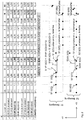
- exemplary 2-dimensional horizontal movements of the smartphones 20 or S1 and 20 'or S2 over an observation period from t (0) to t (10) are shown, the unknown and error-free simulated positions at the discrete times t (i ) are represented by black dots, while the unknown and erroneous simulated positions are indicated by circles are shown.
- the faulty positions are caused by measurement inaccuracies of the acceleration sensors 30 and 30 '.
- the observation period can also extend over significantly more times and / or the time intervals can be smaller or larger or even not equidistant.
- Line 2 contains the unknown x-coordinates of the simulated unknown and error-free positions of the Smartphones 20 at the respective times t (0) to t (10). This is indicated by the notation S1X (t (i)).
- the line 3 contains the unknown y-coordinates of the unknown and error-free positions of the smartphone 20 at the respective times t (0) to t (10). This is indicated by the notation S1Y (t (i)).
- S1Y (t (i)) In Fig. 2
- a point S1 (t (i)) is represented by the coordinates (S1X (t (i)); S1Y (t (i))). This designation also applies to the FIGS. 3 to 6 ,
- Line 4 contains the changes in the x-position coordinate, determined by the acceleration sensor 30, between a time t (i) and an earlier time t (i-1). This is indicated by the notation S1dx (t (i); t (i-1)).
- Line 5 contains the changes in the y-position coordinate between the time t (i) and an earlier time t (i-1) determined by the acceleration sensor 30. This is indicated by the notation S1dy (t (i); t (i-1)).
- the line 6 contains the unknown x-coordinates of the unknown and error-free positions of the smartphone 20 'at the respective times t (0) to t (10). This is indicated by the notation S2X (t (i)).
- the line 7 contains the unknown y-coordinates of the unknown and error-free positions of the smartphone 20 'at the respective times t (0) to t (10). This is indicated by the notation S2Y (t (i)).
- S2Y (t (i)) In Fig. 2 becomes a point S2 (t (i)) by the coordinates (S2X (t (i)); S2Y (t (i))). This designation also applies to the FIGS. 3 to 6 ,
- Line 8 contains the changes of the x-position coordinate between acceleration time sensor 30 'between a time t (i) and an earlier time t (i-1). This is indicated by the notation S2dx (t (i); t (i-1)).
- the line 9 contains the changes in the y-position coordinate, determined by the acceleration sensor 30 ', between a time t (i) and an earlier time t (i-1). This is indicated by the notation S2dy (t (i); t (i-1)).
- exemplary values of a standard deviation of about 7% of the traveled distance were selected and these errors were additionally rounded to increments of 0.05 meters.
- the Values for S1dX, S1dY, S2dX and S2dY were calculated from the given unknown error-free coordinates of a previous point in time by adding up the simulated errors of the respective accelerometer.
- the starting position is defined in the present example by an arbitrary point P1 (X1; Y1) in an X-Y coordinate system for an arbitrary time t (0).
- the user of the smartphone 20 'or a computer program specifies any arbitrary starting position on the smartphone 20', which is stored, for example, in the data memory 52 '.
- the starting position is again defined by an arbitrary point P2 (X2, Y2) in an XY coordinate system for the time t (0). It should be noted that these arbitrary starting points (not shown) i. d. R.
- the user of the smartphone 20 wishes to observe the relative movement of the smartphones 20 and 20 ', ie the distance changes of the unknown distance between the two smartphones 20 and 20' at several times.
- the microprocessor 60 may be configured to reset the position coordinates X and Y to the initially selected starting point after each determination of a position coordinate change. In this way, each position coordinate change with respect to a starting point is determined.
- the determined position coordinate changes with respect to the smartphone 20 are in lines 4 and 5 of the in Fig. 2 entered table. These position coordinate changes are preferably stored together with the associated times in the data memory 52.
- each position coordinate change with respect to the starting point is determined.
- position coordinates X, Y are used as reference quantities, which respectively change by the previously calculated changes of the position coordinates X and Y.
- the determined position coordinate changes with respect to the smartphone 20 ' are shown in lines 8 and 9 of FIG Fig. 2 entered table. These position coordinate changes, together with the associated times, are preferably stored in the data memory 52 'and transmitted to the smartphone 20. There they are stored in the data memory 52.
- a synchronization program can be stored in the smartphones 20 and 20 ', which can be executed by the respective evaluation and control device 60 or 60' to ensure that the timers 70 and 70 'run synchronously with each other.
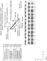
- the graphic A of Fig. 3 shows an enlarged section of two absolute, unknown positions of the smartphone 20 and the smartphone 20 'at a time t (i-1) and the unknown correct positions of the smartphone 20 and the smartphone 20' at the time t (i). Furthermore, in the graph A, the unknown erroneous position of the smartphone 20 and the unknown erroneous position of the smartphone 20 'are each represented by a circle at time t (i). The of the Acceleration sensors 30 and 30 'calculated position coordinate changes are shown in the graph A by the respective horizontal and vertical distances. The erroneous unknown positions of the smartphones 20 and 20 'result from erroneous measurements of the acceleration sensors 30 and 30'. The unknown, error-free route sS1S2 (t (i)) between the smartphone 20 and the smartphone 20 'at the time t (i) is represented by a line drawn in bold.
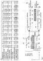
- the Fig. 5 is different from the Fig. 2 Among other things, that now between the two mobile communication devices 20 and S1 and 20 'or S2, two obstacles H1 and H2 occur, which are noticeable in the distance measurement due to the example used distance measuring method and the damping properties of the obstacles as faulty, too long distance measurements do.
- Line 11 contains simulated attenuation values Hi (t (i)) with regard to the two obstacles H1 and H2, which become noticeable as route extensions during the distance measurement by these obstacles.
- Hi (t (i)) At the times t (3) to t (5) and t (9) and t (10), there is a clear view between the smartphones 20 and 20 ', which is represented by the attenuation value 0.
- Line 11 also shows that between the times t (1) and t (2), the attenuation value increases significantly.
- This simulated jump describes the fact that the two smartphones 20 and 20 'have moved at different speeds in the x-direction and thus the distance measurement at time t (2) obliquely and no longer perpendicular to the obstacle H1 is performed.
- the signal transmitted by the smartphone 20 'and received by the smartphone for distance measurement experiences a greater attenuation than at the time t (1).
- Line 11 further indicates that the damping of the obstacle H2 is greater than the damping of the obstacle H2.
- the damping characteristics of each of the obstacles H1 and H2 are nearly identical at each point, and thus the respective length of the path through the obstacle affects the total damping value in a distance measurement.
- Line 12 contains the received signal strength RSS (t (i)) measured by the distance measuring device 80 at times t (0) to t (10) of a signal of known transmission signal strength emitted by the smartphone 20 ', wherein the attenuation by the obstacles H1 and H2 coincides are considered. It should be noted that the two smartphones 20 or S1 and 20 'or S2 can exchange their respective currently used transmission power in advance.
- Line 13 contains the distance measured values sa (t (i)) determined by the distance measuring device 80 from the received signal strengths RSS (t (i)) at the times t (0) to t (10). These values can be stored in the data memory 52. From line 13 it is clear that due to the signal attenuation by the obstacles H1 and H2, the distance measuring device 80 at the times t (0) to t (2) and t (6) to t (8) measures faulty, that is to say too large, stretches.
- n 10.
- the first difference values can also be stored in the data memory 52.
- the evaluation and control device 80 advantageously forms for each instant t (i) the absolute value of the change in distance (line 10) contained in line 10, which is calculated between the time t (i) and the earlier time t (i-1) was the absolute value of the first difference value (line 14) at time t (i), and then a second difference value for each time t (i).
- the evaluation and control device 80 then checks whether the second difference value T1 (i) calculated at a time t (i) is greater in magnitude than a predetermined threshold value in order to detect a faulty distance measurement, for example due to the obstacles H1 and H2.
- the second difference values can also be stored in the data memory 52.
- a more reliable statement about a faulty segment measured value can be made if the evaluation and control unit 80 calculates the standard deviation of the second difference values T1 (i) for each time t (i) and then calculates the quotient T1sig (i) from the second difference values T1 (i ) and their standard deviation sigT1 (i).
- the standard deviation can be calculated assuming normally distributed observations e.g. B. calculated by means of the known error propagation law for normally distributed quantities, which has been done here in all present simulations. In this case, system-related random errors of the distance measuring device 80 and the Acceleration sensors 30 and 30 'considered. Under these conditions, the threshold was set to 3, which corresponds to a threshold of 3 sigma and statistically can be interpreted as at least about a 99% correct decision to a wrong route difference, if the threshold 3 is exceeded only minimally.
- the distance measuring device 80 has measured faulty, that is to say excessively large, distances at times t (0) to t (2) and t (6) to t (8) due to the signal damping by the obstacles H1 and H2 ,
- the evaluation and control device 80 can recognize the sign of the second difference values T1 (i) or T1sig (i) contained in lines 15 or 16 and determine them on the basis of the recognized sign. which and, if appropriate, how many faulty distance measurements can be corrected.
- the second difference value calculated at a time t (i) in the example considered, the value T1sig (i) from line 16, is greater than the threshold value 3 in magnitude and has a negative sign, at least one at an earlier time t (ik) determined distance measured value sa (t (ik)), with k greater than or equal to 1 corrected.
- the positive sign From T1sig (6), the evaluation and control device 80 signals that the obstacle H2 is located between the smartphone 20 and the smartphone 20 'and thus the distance measured value sa (t (6)) measured at time t (6) and optionally at least one measured later in time later sa (t (6 + 1 7)) are faulty due to the obstacle H2 and could be corrected by a forward correction.
- the evaluation and control device 80 can recognize from the values contained in lines 16 and 15, when a distance measurement due to an obstacle is faulty, and whether the faulty distance measurements from a relevant time t (i) to backwards, ie in the past can be corrected or forward corrected by also being able to correct future track measurements.
- the obstacle H1 does not have to be known to the evaluation system for this purpose, too long a measured distance in the signal strength or signal transit time method must always contain the largest systematic error and not the potentially too short measured distance that is compared with it. Similar to the above considerations, it is assumed that the evaluation and control device 80 has recognized that the distance measurements at the times t (0) to t (2) are faulty.
- the faulty distance measurements can be corrected.
- a suitable correction value saK (t (i)) can be determined automatically by the evaluation and control device 80, for example, as a function of the second difference values T1 (i).
- the values T1sig (3), T1sig (6) and T1sig (9) have been identified by the evaluation and control device 80 as those values which have exceeded the threshold of 3 in terms of amount.
- the correction values have a negative Sign, as have been measured as a result of the obstacles H1 and H2 to long distances.
- the correction values saK (t (i)) are in line 17 of the FIG. 6 entered. As can be seen from line 17, the correction values at the times when the distance measurement results have not been corrupted by the obstacles H1 and H2 are set to zero.
- t (8) and backward corrected line measurements sA (t (6) to sA (t (8)) and, for example, select the corrected distance measured values which have been corrected by the smallest correction value, or also consider both correction values differently weighted.
- each obstacle causes only a small and almost uniform attenuation of the RSS signals for all the distance measurements concerned.
- the correction values do not have to be taken over identically for neighboring times, as is the case here, but can each be recalculated.
- a correction value does not have to be linearly dependent on T1 but may additionally take into account the accuracy of T1. A correction value can always be applied even if T1 is different from zero, if this seems statistically meaningful.
- the corrected distance measurements may be used to first or more accurately determine the position of the smartphone 20.
- an algorithm stored in the program memory 50 of the smartphone 20 for determining the position taking into account the corrected distance measured values and the position of the smartphone 20 'of the evaluation and control device 80 are executed. Assume that the GPS receiver 90 of the smartphone 20 is deactivated and a more accurate position of the smartphone 20 at time t (2) is to be determined. In this case, the smartphone 20 requests the smartphone 20 'to transmit its determined position at time t (2) to the smartphone 20.
- the evaluation and control device can now first or more accurately determine the position of the smartphone 20 at time t (2) To determine the absolute position of the smartphone 20 no further measurements, so the absolute position can only be determined as a distance to the absolute position of the smartphone 20 ', so lying on a circle. If the absolute position of the smartphone 20 is not present, so can With the method, the distance determination from, for example, continuous RSS measurements between the two smartphones can be checked and improved, ie only a relative positioning to one another can be improved.
- a geometrical network balancing method known from geodesy can be executed by the evaluation and control device 80 as the algorithm for determining the position, which determines each position of a communication device as an absolute position , Such a method is from the WO2014 / 180845 known.
- a geometric mesh compensation method known from geodesy can be executed by the evaluation and control device 80 as an algorithm for position determination, wherein the coordinate system is arbitrarily defined to the positions in any arbitrary To obtain coordinate system and thus to be able to calculate relative 3-dimensional point positions to each other. Also such a procedure is from the WO2014 / 180845 known.
Landscapes
- Engineering & Computer Science (AREA)
- Radar, Positioning & Navigation (AREA)
- Remote Sensing (AREA)
- Physics & Mathematics (AREA)
- General Physics & Mathematics (AREA)
- Computer Networks & Wireless Communication (AREA)
- Signal Processing (AREA)
- Mobile Radio Communication Systems (AREA)
Claims (20)
- Procédé de reconnaissance d'une valeur de mesure de distance erronée lors d'une mesure de distance entre un premier dispositif de communication mobile (20), qui comprend un dispositif de mesure de distance (80) pour la mesure de la distance et un dispositif de mesure (30) pour la détermination d'une variation de coordonnées de position relative entre deux instants, et au moins un dispositif fixe, comprenant les étapes suivantes :a) mesurer à deux instants t(i - 1) et t(i) successifs, avec i = 1, la distance entre le premier dispositif de communication mobile (20) et le dispositif fixe, afin d'obtenir dans chaque cas une valeur de mesure de distance aux instants t(i) et t(i - 1) ;b) déterminer la modification de coordonnées de position du premier dispositif de communication mobile entre l'instant t(i) et l'instant antérieur t(i - 1) ;c) déterminer pour l'instant t(i) la variation d'écart entre le premier dispositif de communication mobile et le dispositif fixe en fonction de la variation de coordonnées de position du dispositif de communication mobile mesurée entre l'instant t(i) et l'instant antérieur t(i - 1) ;d) calculer pour l'instant t(i) une première valeur de différence à partir de la valeur de mesure de distance mesurée à l'instant t(i) et la valeur de mesure de distance mesurée à l'instant t(i - 1) précédent ;e) calculer pour l'instant t(i) une deuxième valeur de différence entre la première valeur de différence déterminée à l'étape d) pour l'instant t(i) et l'instant t(i - 1) et la variation d'écart déterminée à l'étape c) entre l'instant t(i) et l'instant antérieur t(i - 1) et vérifier si la deuxième valeur de différence présente une grandeur supérieure à celle d'une valeur seuil prédéfinie, afin de reconnaître une valeur de mesure de distance erronée.
- Procédé de reconnaissance d'une valeur de mesure de distance erronée pour une mesure de distance entre un premier dispositif de communication mobile (20), qui comprend un dispositif de mesure de distance (80) pour la mesure de la distance et un dispositif de mesure (30) pour la détermination d'une variation de coordonnées de position relative entre deux instants, et au moins un deuxième dispositif de communication mobile (20'), qui comprend un dispositif de mesure (30') pour la détermination d'une variation de coordonnées de position relative entre deux instants, comprenant les étapes suivantes :a) mesurer à deux instants t(i - 1) et t(i) successifs, avec i = 1, la distance entre le premier dispositif de communication mobile et le deuxième dispositif de communication mobile, afin d'obtenir dans chaque cas une valeur de mesure de distance aux instants t(i) et t(i - 1) ;b1) déterminer la variation de coordonnées de position relative du premier dispositif de communication mobile entre l'instant t(i) et l'instant antérieur t(i - 1) ;b2) déterminer la variation de coordonnées de position relative du deuxième dispositif de communication mobile entre l'instant t(i) et l'instant antérieur t(i - 1) ;c) déterminer pour l'instant t(i) la variation d'écart entre le premier dispositif de communication mobile et le deuxième dispositif de communication mobile en fonction de la variation de coordonnées de position du premier dispositif de communication mobile mesurée entre l'instant t(i) et l'instant t(i - 1) précédent et en fonction de la variation de coordonnées de position du deuxième dispositif de communication mobile mesurée entre l'instant t(i) et l'instant t(i - 1) précédent ;d) calculer pour l'instant t(i) une première valeur de différence à partir de la valeur de mesure de distance mesurée à l'instant t(i) et de la valeur de mesure de distance mesurée à l'instant antérieur t(i - 1) ;e) calculer pour l'instant t(i) une deuxième valeur de différence entre la première valeur de différence déterminée à l'étape d) pour l'instant t(i) et l'instant t(i - 1) et la variation d'écart déterminée à l'étape c) entre l'instant t(i) et l'instant t(i - 1) précédent et vérifier si la deuxième valeur de différence calculée à l'instant t(i) présente une grandeur supérieure à celle d'une valeur seuil prédéfinie, afin de reconnaître une valeur de mesure de distance erronée.
- Procédé selon la revendication 1 ou 2, caractérisé en ce que les étapes a) à e) sont répétées pour plusieurs instants t(i) successifs, avec i = 2, 3, ...n.
- Procédé selon l'une quelconque des revendications précédentes, caractérisé en ce que les étapes a) à e) sont exécutées en commandant le premier dispositif de communication mobile (20).
- Procédé selon les revendications 2, 3 et 4, caractérisé en ce que le deuxième dispositif de communication mobile (20') est invité par le premier dispositif de communication mobile (20) à déterminer ses variations de coordonnées de position et à transmettre les variations de coordonnées de position comprenant les instants correspondants au premier dispositif de communication mobile (20).
- Procédé selon l'une quelconque des revendications 2 à 5, caractérisé en ce que le premier dispositif de communication mobile (20) et le deuxième dispositif de communication mobile (20') sont synchronisés.
- Procédé selon l'une quelconque des revendications précédentes, caractérisé en ce que la valeur seuil prédéfinie est zéro.
- Procédé selon l'une quelconque des revendications précédentes, caractérisé en ce que, à l'étape a), une mesure de distance basée sur l'ISR (intensité du signal reçu) ou une mesure de distance basée sur un temps de propagation entre le premier dispositif de communication mobile (20) et le dispositif fixe ou entre le premier dispositif de communication mobile et le deuxième dispositif de communication mobile (20') est réalisée.
- Procédé selon l'une quelconque des revendications précédentes, caractérisé en ce qu'au moins une valeur de mesure de distance reconnue comme erronée à l'étape e) est corrigée.
- Procédé selon la revendication 9, caractérisé en ce que la valeur de mesure de distance reconnue comme erronée est remplacée par une valeur de correction, laquelle est formée en fonction de la deuxième valeur de différence calculée à l'étape e).
- Procédé selon la revendication 9 ou 10, caractérisé en ce que :les variations d'écart déterminées, les valeurs de mesure de distance obtenues à l'étape a), et les premières valeurs de différence calculées ainsi que les instants t(i) et t(i - 1) respectivement associés sont mis en mémoire dans le premier dispositif de communication mobile (20),et en ce quelorsque la deuxième valeur de différence calculée à l'étape e) à l'instant t(i) présente une grandeur supérieure à celle de la valeur seuil et possède un signe négatif, au moins la valeur de mesure de distance déterminée à l'instant antérieur t (i - k), avec k ≥ 1, est reconnue comme erronée et peut être corrigée,et en ce quelorsque la deuxième valeur de différence calculée à l'étape e) à l'instant t(i) présente une grandeur supérieure à celle de la valeur seuil et possède un signe positif, la valeur de mesure de distance déterminée à l'instant t(i) et au moins la valeur de mesure de distance déterminée à un instant ultérieur t(i + k), avec k ≥ 1, est reconnue comme erronée et peut être corrigée.
- Procédé selon l'une quelconque des revendications précédentes, caractérisé en ce que, dans le premier dispositif de communication mobile (20), un algorithme servant à déterminer la position du premier dispositif de communication mobile, en prenant en considération la valeur de mesure de distance corrigée et la position du dispositif fixe ou du deuxième dispositif de communication mobile (20), est exécuté.
- Procédé selon l'une quelconque des revendications précédentes, caractérisé en ce que, à l'étape c), la grandeur de la variation maximale d'écart est déterminée.
- Système de communication sans fil (10) pour la reconnaissance d'une valeur de mesure de distance erronée lors d'une mesure de distance entre un premier dispositif de communication mobile (20) et un dispositif fixe comprenant :au moins un dispositif fixe,au moins un premier dispositif de communication mobile (20), qui comprend un dispositif de mesure de distance (80) servant à mesurer la distance entre le premier dispositif de communication mobile (20) et le dispositif fixe, un dispositif de mesure (30) servant à mesurer une variation de coordonnées de position relative du premier dispositif de communication mobile (20) entre deux instants, et un dispositif d'évaluation et de commande (60), qui est conçu pour :a) amener le dispositif de mesure de distance à mesurer à deux instants t(i - 1) et t(i) successifs, avec i = 1, la distance entre le premier dispositif de communication mobile (20) et le dispositif fixe, afin d'obtenir dans chaque cas une valeur de mesure de distance aux instants t(i) et t (i - 1) ;b) amener le dispositif de mesure (30) à déterminer une variation de coordonnées de position relative du premier dispositif de communication mobile (20) entre l'instant t(i) et l'instant t(i - 1) précédent ;c) déterminer pour l'instant t(i) la variation d'écart entre le premier dispositif de communication mobile (20) et le dispositif fixe en fonction de la variation de coordonnées de position relative mesurée entre l'instant t(i) et l'instant t(i - 1) précédent ;d) calculer pour l'instant t(i) une première valeur de différence à partir de la valeur de mesure de distance mesurée à l'instant t(i) et la valeur de mesure de distance mesurée à l'instant t(i - 1), ete) calculer pour l'instant t(i) une deuxième valeur de différence entre la première valeur de différence déterminée à la caractéristique d) pour l'instant t(i) et l'instant antérieur t(i - 1) et la variation d'écart déterminée à la caractéristique c) entre l'instant t(i) et l'instant t(i - 1) précédent et vérifier si la grandeur de la deuxième valeur de différence calculée à l'instant t(i) est supérieure à celle d'une valeur seuil prédéfinie ou égale à une valeur seuil prédéfinie, afin de reconnaître une valeur de mesure de distance erronée.
- Système de communication sans fil (10) pour la reconnaissance d'une valeur de mesure de distance erronée pour une mesure de distance entre au moins deux dispositifs de communication mobiles, comprenant un premier dispositif de communication mobile (20) qui comporte un dispositif de mesure de distance (80) pour la mesure de la distance entre le premier dispositif de communication mobile et au moins un deuxième dispositif de communication mobile (20'), un dispositif de mesure (30) pour la mesure d'une variation de coordonnées de position relative du premier dispositif de communication mobile entre deux instants, et un dispositif d'évaluation et de commande (60),
dans lequel ledit au moins un deuxième dispositif de communication mobiles (20') comprend un dispositif de mesure (30') pour la mesure d'une variation de coordonnées de position relative du deuxième dispositif de communication mobile (20') entre deux instants et un dispositif d'évaluation et de commande (60'),
dans lequel le dispositif d'évaluation et de commande (60) du premier dispositif de communication mobile (20) est conçu pour :a) amener le dispositif de mesure de distance (80) à mesurer à deux instants successifs t(i - 1) et t(i), avec i = 1, la distance entre le premier dispositif de communication mobile (20) et le deuxième dispositif de communication mobile (20'), afin d'obtenir dans chaque cas une valeur de mesure de distance aux instants t(i) et t(i - 1) ;b1) amener le dispositif de mesure (30) du premier dispositif de communication mobile (20) à déterminer une variation de coordonnées de position relative du premier dispositif de communication mobile (20) entre l'instant t(i) et l'instant t(i - 1) précédent ;b2) amener le dispositif de mesure (30') du deuxième dispositif de communication mobile (20') à déterminer une variation de coordonnées de position relative du deuxième dispositif de communication mobile (20') entre l'instant t(i) et l'instant t(i - 1) précédent, et inviter le deuxième dispositif de communication mobile (20') à transmettre les variations de coordonnées de position relative et les instants associés au premier dispositif de communication mobile (20),c) déterminer pour l'instant t(i) la variation d'écart entre le premier dispositif de communication mobile (20) et le deuxième dispositif de communication mobile (20') en fonction de la variation de coordonnées de position du premier dispositif de communication mobile (20) mesurée entre l'instant t(i) et l'instant t(i - 1) précédent et en fonction de la variation de coordonnées de position du deuxième dispositif de communication mobile (20') mesurée entre l'instant t(i) et l'instant t(i - 1) précédent ;d) calculer pour l'instant t(i) une première valeur de différence à partir de la valeur de mesure de distance mesurée à l'instant t(i) et de la valeur de mesure de distance mesurée à l'instant t(i - 1), ete) calculer pour l'instant t(i) une deuxième valeur de différence entre la première valeur de différence déterminée à la caractéristique d) pour l'instant t(i) et l'instant antérieur t(i - 1) et la variation d'écart déterminée à la caractéristique c) entre l'instant t(i) et l'instant t(i - 1) précédent et vérifier si la deuxième valeur de différence calculée à l'instant t(i) présente une grandeur supérieure à celle d'une valeur seuil prédéfinie ou égale à une valeur seuil prédéfinie, afin de reconnaître une valeur de mesure de distance erronée. - Système de communication sans fil selon la revendication 14 ou 15, caractérisé en ce que le dispositif d'évaluation et de commande (60) du premier dispositif de communication mobile (20) est conçu pour répéter les caractéristiques a) à e) pour plusieurs instants t(i) successifs, avec i = 2, 3, ...n.
- Système de communication sans fil selon l'une quelconque des revendications 14 à 16, caractérisé en ce que le dispositif d'évaluation et de commande (60) du premier dispositif de communication mobile (20) est conçu pour corriger une valeur de mesure de distance reconnue comme erronée.
- Système de communication sans fil selon l'une quelconque des revendications 14 à 17, caractérisé en ce que le dispositif d'évaluation et de commande (60) du premier dispositif de communication mobile (20) est conçu pour exécuter un algorithme servant à déterminer la position du premier dispositif de communication mobile (20) à l'instant t(i) en prenant en considération la valeur de mesure de distance corrigée et la position du dispositif fixe ou du deuxième dispositif de communication mobile (20').
- Système de communication sans fil selon l'une quelconque des revendications 14 à 18, caractérisé en ce que le dispositif de mesure (30 ; 30') des premier et deuxième dispositifs de communication mobiles contient un dispositif de mesure d'accélération respectif, et en ce que le dispositif de mesure de distance (60) est conçu pour réaliser une mesure de distance basée sur l'ISR (intensité du signal reçu) ou une mesure de distance basée sur un temps de propagation entre le premier dispositif de communication mobile (20) et le dispositif fixe ou entre le premier dispositif de communication mobile (20) et le deuxième dispositif de communication mobile (20').
- Programme informatique contenant :une pluralité d'instructions qui peuvent être mises en mémoire au moins dans un dispositif de communication mobile (20), dans lequel les instructions, lorsqu'elles sont lues et traitées par un dispositif d'évaluation et de commande (60) du dispositif de communication mobile (20), exécutent le procédé selon l'une quelconque des revendications 1 à 13.
Priority Applications (1)
| Application Number | Priority Date | Filing Date | Title |
|---|---|---|---|
| EP15167304.3A EP3094143B1 (fr) | 2015-05-12 | 2015-05-12 | Systèmes de communication sans fil et procédés de reconnaissance d'une valeur mesurée erronée lors de la mesure de chemin entre deux dispositifs |
Applications Claiming Priority (1)
| Application Number | Priority Date | Filing Date | Title |
|---|---|---|---|
| EP15167304.3A EP3094143B1 (fr) | 2015-05-12 | 2015-05-12 | Systèmes de communication sans fil et procédés de reconnaissance d'une valeur mesurée erronée lors de la mesure de chemin entre deux dispositifs |
Publications (2)
| Publication Number | Publication Date |
|---|---|
| EP3094143A1 EP3094143A1 (fr) | 2016-11-16 |
| EP3094143B1 true EP3094143B1 (fr) | 2017-08-30 |
Family
ID=53181086
Family Applications (1)
| Application Number | Title | Priority Date | Filing Date |
|---|---|---|---|
| EP15167304.3A Active EP3094143B1 (fr) | 2015-05-12 | 2015-05-12 | Systèmes de communication sans fil et procédés de reconnaissance d'une valeur mesurée erronée lors de la mesure de chemin entre deux dispositifs |
Country Status (1)
| Country | Link |
|---|---|
| EP (1) | EP3094143B1 (fr) |
Families Citing this family (1)
| Publication number | Priority date | Publication date | Assignee | Title |
|---|---|---|---|---|
| CN117573389B (zh) * | 2023-11-16 | 2025-04-04 | 宁波宇宁软件技术有限公司 | 应用程序的调用方法、终端设备及介质 |
Family Cites Families (3)
| Publication number | Priority date | Publication date | Assignee | Title |
|---|---|---|---|---|
| KR101440836B1 (ko) * | 2010-07-08 | 2014-11-04 | 에스케이텔레콤 주식회사 | 무선랜 신호를 이용한 측위 오차 판별 방법 및 장치 |
| CN106125042A (zh) * | 2012-01-09 | 2016-11-16 | 香港商曦恩体感科技股份有限公司 | 进行定位的方法和电子装置 |
| DE102013104727A1 (de) | 2013-05-07 | 2014-11-13 | Deutsche Telekom Ag | Verfahren und Vorrichtungen zum Bestimmen der Position einer beweglichen Kommunikationseinrichtung |
-
2015
- 2015-05-12 EP EP15167304.3A patent/EP3094143B1/fr active Active
Non-Patent Citations (1)
| Title |
|---|
| None * |
Also Published As
| Publication number | Publication date |
|---|---|
| EP3094143A1 (fr) | 2016-11-16 |
Similar Documents
| Publication | Publication Date | Title |
|---|---|---|
| EP3655799B1 (fr) | Procédé pour produire et améliorer une distribution de probabilités de position pour des données reçues par gnss | |
| DE102016120235B4 (de) | Verfahren und System zum Ermitteln einer Position einer mobilen Vorrichtung | |
| WO2015075093A1 (fr) | Procédé, filtre de fusion et système de fusion de signaux de détection avec différents retards de sortie de signal pour former un jeu de données de fusion | |
| EP2656096B1 (fr) | Détermination de position | |
| DE102016109395B4 (de) | Steuerungssystem für ein Fahrzeug | |
| EP3329216A1 (fr) | Détermination d'une information de disposition pour un véhicule | |
| DE102012216211A1 (de) | Verfahren zum Auswählen eines Satelliten | |
| DE102018104090A1 (de) | Adaptive beschreibung von prozessrauschen für verbesserte kalman-filter-zielverfolgung | |
| DE102013104727A1 (de) | Verfahren und Vorrichtungen zum Bestimmen der Position einer beweglichen Kommunikationseinrichtung | |
| WO2014095558A2 (fr) | Procédé pour fournir un signal gnss | |
| DE102010011982A1 (de) | Verfahren zum rechnergestützten Erstellen und/oder Aktualisieren einer Referenzkarte für eine satellitengestützte Ortung eines Objekts | |
| DE102014211177A1 (de) | Verfahren und System zur echtzeitfähigen Bereitstellung von dynamischen Fehlerwerten dynamischer Messwerte | |
| EP3610224B1 (fr) | Procédé, dispositif et support d'enregistrement lisible par ordinateur comprenant des instructions servant à estimer une position d'un véhicule automobile | |
| EP3094143B1 (fr) | Systèmes de communication sans fil et procédés de reconnaissance d'une valeur mesurée erronée lors de la mesure de chemin entre deux dispositifs | |
| DE102019208872A1 (de) | Verfahren zur Fehlerbewertung bei einer Positionsbestimmung | |
| EP3295126B1 (fr) | Procédé pour la détermination d'états d'un système au moyen d'un filtre d'estimation | |
| DE102008023242A1 (de) | Map matching für Sicherheitsanwendungen | |
| WO2022018007A1 (fr) | Procédé d'estimation d'un mouvement ego d'un véhicule sur la base de mesures d'un capteur lidar et dispositif informatique | |
| EP3491335B1 (fr) | Procédé et dispositif pour déterminer la position absolue d'un véhicule à moteur, système de localisation, véhicule à moteur | |
| EP3698103A1 (fr) | Estimation de la précision de mesure de différents capteurs pour la même grandeur de mesure | |
| DE102008037174A1 (de) | Verfahren und Vorrichtung zum Optimieren der Genauigkeit der Positionsbestimmung und/oder zum Verringern des Integritätsrisikos eines Empfängers in einem globalen Satellitennavigationssystem | |
| EP2921880B1 (fr) | Procédé et dispositif de communication mobile pour la détermination améliorée de la position actuelle en temps réel | |
| DE102024201996A1 (de) | Robuste Selbstlokalisierung mit Satellitennavigation | |
| DE102015107421B4 (de) | Drahtloses Kommunikationssystem und Verfahren zum Berechnen von Abstandsänderungen zwischen zwei mobilen Kommunikationseinrichtungen | |
| DE102025117174A1 (de) | Verfahren und Vorrichtung zur Ermittlung und/oder Verfolgung eines Objekts in einer Fahrzeugumgebung |
Legal Events
| Date | Code | Title | Description |
|---|---|---|---|
| PUAI | Public reference made under article 153(3) epc to a published international application that has entered the european phase |
Free format text: ORIGINAL CODE: 0009012 |
|
| AK | Designated contracting states |
Kind code of ref document: A1 Designated state(s): AL AT BE BG CH CY CZ DE DK EE ES FI FR GB GR HR HU IE IS IT LI LT LU LV MC MK MT NL NO PL PT RO RS SE SI SK SM TR |
|
| AX | Request for extension of the european patent |
Extension state: BA ME |
|
| GRAP | Despatch of communication of intention to grant a patent |
Free format text: ORIGINAL CODE: EPIDOSNIGR1 |
|
| 17P | Request for examination filed |
Effective date: 20170217 |
|
| RBV | Designated contracting states (corrected) |
Designated state(s): AL AT BE BG CH CY CZ DE DK EE ES FI FR GB GR HR HU IE IS IT LI LT LU LV MC MK MT NL NO PL PT RO RS SE SI SK SM TR |
|
| INTG | Intention to grant announced |
Effective date: 20170328 |
|
| GRAS | Grant fee paid |
Free format text: ORIGINAL CODE: EPIDOSNIGR3 |
|
| GRAA | (expected) grant |
Free format text: ORIGINAL CODE: 0009210 |
|
| AK | Designated contracting states |
Kind code of ref document: B1 Designated state(s): AL AT BE BG CH CY CZ DE DK EE ES FI FR GB GR HR HU IE IS IT LI LT LU LV MC MK MT NL NO PL PT RO RS SE SI SK SM TR |
|
| REG | Reference to a national code |
Ref country code: GB Ref legal event code: FG4D Free format text: NOT ENGLISH |
|
| REG | Reference to a national code |
Ref country code: CH Ref legal event code: EP |
|
| REG | Reference to a national code |
Ref country code: AT Ref legal event code: REF Ref document number: 924781 Country of ref document: AT Kind code of ref document: T Effective date: 20170915 |
|
| REG | Reference to a national code |
Ref country code: IE Ref legal event code: FG4D Free format text: LANGUAGE OF EP DOCUMENT: GERMAN |
|
| REG | Reference to a national code |
Ref country code: DE Ref legal event code: R096 Ref document number: 502015001771 Country of ref document: DE |
|
| REG | Reference to a national code |
Ref country code: NL Ref legal event code: MP Effective date: 20170830 |
|
| REG | Reference to a national code |
Ref country code: LT Ref legal event code: MG4D |
|
| PG25 | Lapsed in a contracting state [announced via postgrant information from national office to epo] |
Ref country code: SE Free format text: LAPSE BECAUSE OF FAILURE TO SUBMIT A TRANSLATION OF THE DESCRIPTION OR TO PAY THE FEE WITHIN THE PRESCRIBED TIME-LIMIT Effective date: 20170830 Ref country code: HR Free format text: LAPSE BECAUSE OF FAILURE TO SUBMIT A TRANSLATION OF THE DESCRIPTION OR TO PAY THE FEE WITHIN THE PRESCRIBED TIME-LIMIT Effective date: 20170830 Ref country code: NO Free format text: LAPSE BECAUSE OF FAILURE TO SUBMIT A TRANSLATION OF THE DESCRIPTION OR TO PAY THE FEE WITHIN THE PRESCRIBED TIME-LIMIT Effective date: 20171130 Ref country code: LT Free format text: LAPSE BECAUSE OF FAILURE TO SUBMIT A TRANSLATION OF THE DESCRIPTION OR TO PAY THE FEE WITHIN THE PRESCRIBED TIME-LIMIT Effective date: 20170830 Ref country code: FI Free format text: LAPSE BECAUSE OF FAILURE TO SUBMIT A TRANSLATION OF THE DESCRIPTION OR TO PAY THE FEE WITHIN THE PRESCRIBED TIME-LIMIT Effective date: 20170830 |
|
| PG25 | Lapsed in a contracting state [announced via postgrant information from national office to epo] |
Ref country code: RS Free format text: LAPSE BECAUSE OF FAILURE TO SUBMIT A TRANSLATION OF THE DESCRIPTION OR TO PAY THE FEE WITHIN THE PRESCRIBED TIME-LIMIT Effective date: 20170830 Ref country code: ES Free format text: LAPSE BECAUSE OF FAILURE TO SUBMIT A TRANSLATION OF THE DESCRIPTION OR TO PAY THE FEE WITHIN THE PRESCRIBED TIME-LIMIT Effective date: 20170830 Ref country code: GR Free format text: LAPSE BECAUSE OF FAILURE TO SUBMIT A TRANSLATION OF THE DESCRIPTION OR TO PAY THE FEE WITHIN THE PRESCRIBED TIME-LIMIT Effective date: 20171201 Ref country code: BG Free format text: LAPSE BECAUSE OF FAILURE TO SUBMIT A TRANSLATION OF THE DESCRIPTION OR TO PAY THE FEE WITHIN THE PRESCRIBED TIME-LIMIT Effective date: 20171130 Ref country code: LV Free format text: LAPSE BECAUSE OF FAILURE TO SUBMIT A TRANSLATION OF THE DESCRIPTION OR TO PAY THE FEE WITHIN THE PRESCRIBED TIME-LIMIT Effective date: 20170830 Ref country code: IS Free format text: LAPSE BECAUSE OF FAILURE TO SUBMIT A TRANSLATION OF THE DESCRIPTION OR TO PAY THE FEE WITHIN THE PRESCRIBED TIME-LIMIT Effective date: 20171230 |
|
| PG25 | Lapsed in a contracting state [announced via postgrant information from national office to epo] |
Ref country code: NL Free format text: LAPSE BECAUSE OF FAILURE TO SUBMIT A TRANSLATION OF THE DESCRIPTION OR TO PAY THE FEE WITHIN THE PRESCRIBED TIME-LIMIT Effective date: 20170830 |
|
| PG25 | Lapsed in a contracting state [announced via postgrant information from national office to epo] |
Ref country code: DK Free format text: LAPSE BECAUSE OF FAILURE TO SUBMIT A TRANSLATION OF THE DESCRIPTION OR TO PAY THE FEE WITHIN THE PRESCRIBED TIME-LIMIT Effective date: 20170830 Ref country code: PL Free format text: LAPSE BECAUSE OF FAILURE TO SUBMIT A TRANSLATION OF THE DESCRIPTION OR TO PAY THE FEE WITHIN THE PRESCRIBED TIME-LIMIT Effective date: 20170830 Ref country code: CZ Free format text: LAPSE BECAUSE OF FAILURE TO SUBMIT A TRANSLATION OF THE DESCRIPTION OR TO PAY THE FEE WITHIN THE PRESCRIBED TIME-LIMIT Effective date: 20170830 |
|
| REG | Reference to a national code |
Ref country code: FR Ref legal event code: PLFP Year of fee payment: 4 |
|
| PG25 | Lapsed in a contracting state [announced via postgrant information from national office to epo] |
Ref country code: EE Free format text: LAPSE BECAUSE OF FAILURE TO SUBMIT A TRANSLATION OF THE DESCRIPTION OR TO PAY THE FEE WITHIN THE PRESCRIBED TIME-LIMIT Effective date: 20170830 Ref country code: SK Free format text: LAPSE BECAUSE OF FAILURE TO SUBMIT A TRANSLATION OF THE DESCRIPTION OR TO PAY THE FEE WITHIN THE PRESCRIBED TIME-LIMIT Effective date: 20170830 Ref country code: IT Free format text: LAPSE BECAUSE OF FAILURE TO SUBMIT A TRANSLATION OF THE DESCRIPTION OR TO PAY THE FEE WITHIN THE PRESCRIBED TIME-LIMIT Effective date: 20170830 Ref country code: SM Free format text: LAPSE BECAUSE OF FAILURE TO SUBMIT A TRANSLATION OF THE DESCRIPTION OR TO PAY THE FEE WITHIN THE PRESCRIBED TIME-LIMIT Effective date: 20170830 |
|
| REG | Reference to a national code |
Ref country code: DE Ref legal event code: R097 Ref document number: 502015001771 Country of ref document: DE |
|
| PLBE | No opposition filed within time limit |
Free format text: ORIGINAL CODE: 0009261 |
|
| STAA | Information on the status of an ep patent application or granted ep patent |
Free format text: STATUS: NO OPPOSITION FILED WITHIN TIME LIMIT |
|
| 26N | No opposition filed |
Effective date: 20180531 |
|
| PG25 | Lapsed in a contracting state [announced via postgrant information from national office to epo] |
Ref country code: SI Free format text: LAPSE BECAUSE OF FAILURE TO SUBMIT A TRANSLATION OF THE DESCRIPTION OR TO PAY THE FEE WITHIN THE PRESCRIBED TIME-LIMIT Effective date: 20170830 |
|
| PG25 | Lapsed in a contracting state [announced via postgrant information from national office to epo] |
Ref country code: MT Free format text: LAPSE BECAUSE OF FAILURE TO SUBMIT A TRANSLATION OF THE DESCRIPTION OR TO PAY THE FEE WITHIN THE PRESCRIBED TIME-LIMIT Effective date: 20170830 |
|
| REG | Reference to a national code |
Ref country code: CH Ref legal event code: PL |
|
| REG | Reference to a national code |
Ref country code: BE Ref legal event code: MM Effective date: 20180531 |
|
| PG25 | Lapsed in a contracting state [announced via postgrant information from national office to epo] |
Ref country code: MC Free format text: LAPSE BECAUSE OF FAILURE TO SUBMIT A TRANSLATION OF THE DESCRIPTION OR TO PAY THE FEE WITHIN THE PRESCRIBED TIME-LIMIT Effective date: 20170830 |
|
| REG | Reference to a national code |
Ref country code: IE Ref legal event code: MM4A |
|
| PG25 | Lapsed in a contracting state [announced via postgrant information from national office to epo] |
Ref country code: CH Free format text: LAPSE BECAUSE OF NON-PAYMENT OF DUE FEES Effective date: 20180531 Ref country code: LI Free format text: LAPSE BECAUSE OF NON-PAYMENT OF DUE FEES Effective date: 20180531 |
|
| PG25 | Lapsed in a contracting state [announced via postgrant information from national office to epo] |
Ref country code: LU Free format text: LAPSE BECAUSE OF NON-PAYMENT OF DUE FEES Effective date: 20180512 |
|
| PG25 | Lapsed in a contracting state [announced via postgrant information from national office to epo] |
Ref country code: IE Free format text: LAPSE BECAUSE OF NON-PAYMENT OF DUE FEES Effective date: 20180512 |
|
| PG25 | Lapsed in a contracting state [announced via postgrant information from national office to epo] |
Ref country code: BE Free format text: LAPSE BECAUSE OF NON-PAYMENT OF DUE FEES Effective date: 20180531 |
|
| PG25 | Lapsed in a contracting state [announced via postgrant information from national office to epo] |
Ref country code: TR Free format text: LAPSE BECAUSE OF FAILURE TO SUBMIT A TRANSLATION OF THE DESCRIPTION OR TO PAY THE FEE WITHIN THE PRESCRIBED TIME-LIMIT Effective date: 20170830 |
|
| PG25 | Lapsed in a contracting state [announced via postgrant information from national office to epo] |
Ref country code: PT Free format text: LAPSE BECAUSE OF FAILURE TO SUBMIT A TRANSLATION OF THE DESCRIPTION OR TO PAY THE FEE WITHIN THE PRESCRIBED TIME-LIMIT Effective date: 20170830 |
|
| PG25 | Lapsed in a contracting state [announced via postgrant information from national office to epo] |
Ref country code: HU Free format text: LAPSE BECAUSE OF FAILURE TO SUBMIT A TRANSLATION OF THE DESCRIPTION OR TO PAY THE FEE WITHIN THE PRESCRIBED TIME-LIMIT; INVALID AB INITIO Effective date: 20150512 Ref country code: CY Free format text: LAPSE BECAUSE OF FAILURE TO SUBMIT A TRANSLATION OF THE DESCRIPTION OR TO PAY THE FEE WITHIN THE PRESCRIBED TIME-LIMIT Effective date: 20170830 Ref country code: RO Free format text: LAPSE BECAUSE OF FAILURE TO SUBMIT A TRANSLATION OF THE DESCRIPTION OR TO PAY THE FEE WITHIN THE PRESCRIBED TIME-LIMIT Effective date: 20170830 Ref country code: MK Free format text: LAPSE BECAUSE OF NON-PAYMENT OF DUE FEES Effective date: 20170830 |
|
| PG25 | Lapsed in a contracting state [announced via postgrant information from national office to epo] |
Ref country code: AL Free format text: LAPSE BECAUSE OF FAILURE TO SUBMIT A TRANSLATION OF THE DESCRIPTION OR TO PAY THE FEE WITHIN THE PRESCRIBED TIME-LIMIT Effective date: 20170830 |
|
| REG | Reference to a national code |
Ref country code: AT Ref legal event code: MM01 Ref document number: 924781 Country of ref document: AT Kind code of ref document: T Effective date: 20200512 |
|
| PG25 | Lapsed in a contracting state [announced via postgrant information from national office to epo] |
Ref country code: AT Free format text: LAPSE BECAUSE OF NON-PAYMENT OF DUE FEES Effective date: 20200512 |
|
| PGFP | Annual fee paid to national office [announced via postgrant information from national office to epo] |
Ref country code: FR Payment date: 20241220 Year of fee payment: 11 |
|
| PGFP | Annual fee paid to national office [announced via postgrant information from national office to epo] |
Ref country code: DE Payment date: 20241212 Year of fee payment: 11 |
|
| PGFP | Annual fee paid to national office [announced via postgrant information from national office to epo] |
Ref country code: GB Payment date: 20250522 Year of fee payment: 11 |