EP3094409B1 - Détachement d'une charge adhérant à la paroi intérieure d'un tube broyeur - Google Patents
Détachement d'une charge adhérant à la paroi intérieure d'un tube broyeur Download PDFInfo
- Publication number
- EP3094409B1 EP3094409B1 EP15711688.0A EP15711688A EP3094409B1 EP 3094409 B1 EP3094409 B1 EP 3094409B1 EP 15711688 A EP15711688 A EP 15711688A EP 3094409 B1 EP3094409 B1 EP 3094409B1
- Authority
- EP
- European Patent Office
- Prior art keywords
- grinding tube
- tube
- charge
- grinding
- drive
- Prior art date
- Legal status (The legal status is an assumption and is not a legal conclusion. Google has not performed a legal analysis and makes no representation as to the accuracy of the status listed.)
- Active
Links
Images



Classifications
-
- B—PERFORMING OPERATIONS; TRANSPORTING
- B02—CRUSHING, PULVERISING, OR DISINTEGRATING; PREPARATORY TREATMENT OF GRAIN FOR MILLING
- B02C—CRUSHING, PULVERISING, OR DISINTEGRATING IN GENERAL; MILLING GRAIN
- B02C17/00—Disintegrating by tumbling mills, i.e. mills having a container charged with the material to be disintegrated with or without special disintegrating members such as pebbles or balls
- B02C17/18—Details
- B02C17/1805—Monitoring devices for tumbling mills
-
- B—PERFORMING OPERATIONS; TRANSPORTING
- B02—CRUSHING, PULVERISING, OR DISINTEGRATING; PREPARATORY TREATMENT OF GRAIN FOR MILLING
- B02C—CRUSHING, PULVERISING, OR DISINTEGRATING IN GENERAL; MILLING GRAIN
- B02C17/00—Disintegrating by tumbling mills, i.e. mills having a container charged with the material to be disintegrated with or without special disintegrating members such as pebbles or balls
-
- B—PERFORMING OPERATIONS; TRANSPORTING
- B02—CRUSHING, PULVERISING, OR DISINTEGRATING; PREPARATORY TREATMENT OF GRAIN FOR MILLING
- B02C—CRUSHING, PULVERISING, OR DISINTEGRATING IN GENERAL; MILLING GRAIN
- B02C17/00—Disintegrating by tumbling mills, i.e. mills having a container charged with the material to be disintegrated with or without special disintegrating members such as pebbles or balls
- B02C17/18—Details
-
- B—PERFORMING OPERATIONS; TRANSPORTING
- B02—CRUSHING, PULVERISING, OR DISINTEGRATING; PREPARATORY TREATMENT OF GRAIN FOR MILLING
- B02C—CRUSHING, PULVERISING, OR DISINTEGRATING IN GENERAL; MILLING GRAIN
- B02C17/00—Disintegrating by tumbling mills, i.e. mills having a container charged with the material to be disintegrated with or without special disintegrating members such as pebbles or balls
- B02C17/18—Details
- B02C17/24—Driving mechanisms
-
- B—PERFORMING OPERATIONS; TRANSPORTING
- B02—CRUSHING, PULVERISING, OR DISINTEGRATING; PREPARATORY TREATMENT OF GRAIN FOR MILLING
- B02C—CRUSHING, PULVERISING, OR DISINTEGRATING IN GENERAL; MILLING GRAIN
- B02C25/00—Control arrangements specially adapted for crushing or disintegrating
Definitions
- the invention relates to a method for releasing an adhering charge from an inner wall of a grinding tube and to an arrangement for releasing an adhering charge from an inner wall of a grinding tube.
- Tube mills are preferably used for grinding brittle material, in particular ore.
- the grinding process takes place in a horizontally oriented grinding tube of the tube mill.
- the grinding tube filled with a charge rotates about its longitudinal axis during the grinding process.
- Typical tube mills may have a grinding tube with a diameter of 2m to 11m and a length of up to 25m.
- the drive power of such tube mills is usually in the range of 5MW to 15MW, whereby preferably so-called slip ring rotor motors are used.
- tube mills are therefore equipped with devices which detect the presence of an adhering charge and, in the event of detection of an adhering charge, stop the tube mill or the rotation of the milling tube. If an adhering charge is detected and the tube mill is consequently stopped, then the adhering charge must be released from the inner wall of the grinding tube.
- the adhesive charge can be released using personnel using tools, in particular pneumatic hammers.
- the disclosed WO 2005/092508 A1 a method in which a drive device of the grinding tube for targeted release of the charge is driven to a swinging or swelling rotation of the grinding tube.
- the EP 2 525 914 B1 a method in which a torque applied to the milling tube drive torque is increased by a reference torque varying.
- the invention has for its object to allow an energy-efficient release of an adhering charge while using relatively simple drive and control technology.
- the grinding tube from a predetermined, assumed rotational position is driven by the weight the adhering charge turned back, wherein at least one movement state quantity of the grinding tube is determined.
- the predefinable, assumed rotational position can be a rotational position in which a sufficiently high restoring torque acts on the grinding tube about an axis of rotation of the grinding tube.
- the restoring moment can result from a weight of the adhering charge or from the product of the weight and a lever arm.
- the restoring torque can be considered sufficiently high if it can cause an automatic turning back of the grinding tube in the direction of a rotational starting position or towards a stable equilibrium position of the grinding tube.
- the grinding tube is driven back by the force of gravity or the restoring torque, ie accelerated, or automatically turns in the direction of the equilibrium position.
- a driving device which drives the grinding tube during a grinding operation and which may, for example, comprise a slip-ring motor, is disengaged and / or switched off during the turning-back and / or in an idling position.
- the at least one determined movement state variable may be a rotation angle and / or a rotational angular velocity and / or a rotational angular acceleration of the milling tube.
- Determined is, in the context and in the following, an appropriate determination, a determination, a measurement - in an indirect or direct way - or a calculation of a value to understand.
- the grinding tube is braked as a function of the at least one determined state of motion variable for releasing the adhering charge from the inner wall of the grinding tube.
- the dependence lies in achieving a predefinable and / or determined rotational angular velocity and / or rotational angular acceleration of the grinding tube.
- the grinding tube is braked as soon as it has automatically reached a certain rotational angular velocity.
- the grinding tube is braked by a braking device, such as a service brake and / or a parking brake.
- the grinding tube can be braked, so with a high change in rotational angular acceleration over a time and / or until a certain delay is reached.
- a suitably set up control or regulation arrangement for activating the braking device to effect a predefinable delay.
- the method provides that the grinding tube automatically turns into a rotation position in a rotational position in which a sufficiently high restoring torque acts by the weight of the adhering charge and when it reaches it a predetermined rotational angular velocity, a brake is controlled so targeted or metered that it comes as a result of a mass inertial force thus caused advantageously to a release of the adhering charge from the inner wall of the grinding tube.
- the invention also provides an arrangement for releasing an adhered charge from an inner wall of a grinding tube.
- the arrangement has a detection device, a drive unit, a brake device and a control device.
- the determination device is set up such that at least one movement state variable of the grinding tube can be determined.
- the determination device can be equipped with appropriate measurement technology or sensors in order to determine preferably a rotation angle and / or a rotational angular velocity and / or a rotational angular acceleration (also: angular retardation / deceleration) of the milling tube.
- a rotation angle and / or a rotational angular velocity and / or a rotational angular acceleration also: angular retardation / deceleration
- the angle of rotation and the rotational speed can be determined particularly cost-effectively and reliably.
- the braking device is set up to decelerate the grinding tube with a predeterminable delay.
- the brake device to a service brake and / or a parking brake, which are each prepared to decelerate the grinding tube.
- the braking device may be prepared for transmitting a brake pressure and / or a braking force and / or a braking torque to the grinding pipe.
- the brake device is prepared so that the brake pressure and / or the braking force and / or the braking torque can be controlled or regulated.
- the brake pressure and / or the braking force and / or the braking torque are generated hydraulically.
- the control device is set up for activating the braking device as a function of the at least one determined state of motion variable and for activating the drive unit to switch off a drive activity of the drive unit at a predefinable, assumed rotational position of the grinding tube.
- control device is configured to control the brake pressure and / or the braking force and / or the braking torque of the braking device.
- the control can be carried out in particular as a function of the rotational angular velocity of the grinding tube determined by the determining device.
- the invention and / or any further development described can also be realized by a computer program product which has a storage medium on which a computer program is stored which carries out the invention and / or the development.
- the predefinable, assumed rotational position is achieved by a driven rotation of the grinding tube.
- the driven rotation can be effected by a main or sub drive or a driving device of the grinding tube.
- the predefinable, assumed rotational position is expediently a position of the grinding tube, in which a sufficiently large restoring moment is caused by the weight of the adhering charge.
- a restoring moment can be sufficiently great if it can cause a drive-free, ie automatic, turning of the grinding tube in the direction of or tangential to the weight of the adhering charge.
- the assumed rotational position can be assumed by a rotation by an absolute rotational angle between 80 ° and 130 °, starting from a rotational equilibrium position of the grinding tube.
- the driven assumed rotational position is a position in which it can advantageously not come to an unwanted detachment or falling of the adhering charge.
- the driven rotation of the milling tube against the weight of the adhered charge increases a potential energy of the adhered charge.
- the energy thus built up can be converted into kinetic energy by simply turning the grinding tube back and forth. This kinetic energy is then available to dissolve the adherent charge. In this way, a drive technology particularly simple release of the adhering charge can be achieved because the adhesive charge needs to be rotated only in a predetermined rotational position.
- the predefinable, assumed rotational position of the grinding tube is predetermined by a rotational angle determined as a function of a charge property.
- the charge property may be a charge amount or a filling level of the grinding tube and / or a material-specific characteristic value and / or an empirical value assigned to the charge.
- the rotational position may be 40 °, at another particular position 80 °, depending on the charge characteristics.
- the assumed rotational position of the grinding tube is predetermined by a rotation angle with an amount between 40 ° and 80 °, starting from a stable equilibrium position of the grinding tube.
- the stable equilibrium position of the milling tube may be a rotational position of the milling tube in which the potential energy of the adhering charge is minimal and / or not sufficiently high to cause an automatic, drive-free rotation of the grinding tube. Typically, this position is achieved in a so-called 6 o'clock position of adherent charge.
- the at least one determined movement state variable is a rotation angle and / or a rotational angular velocity and / or a rotational angular acceleration of the milling tube.
- both the rotation angle and the rotational angular velocity can be determined with a speedometer.
- the grinding tube is braked during the turning back at least once to a standstill.
- the grinding tube is jerky, so slowed down to a standstill with a maximum change in rotational angular acceleration over time. So can easy on A particularly high inertial force of the adhering charge and a correspondingly high releasing force are caused to the adhering charge.
- the grinding tube can also be braked more than once, in particular when, after braking to standstill, it is again set in rotation without drive.
- the grinding tube is braked during the turning back at least once with a predetermined delay.
- the predefinable delay may be an upper or a lower limit.
- An upper limit may in particular result from a load limit of the tube mill or the grinding tube, in particular its drive device and / or braking device.
- an upper limit value may be a value whose exceeding is to be expected as a result of excessively high inertia-related mechanical stress having an adverse effect on the function of the tube mill.
- a lower limit may be a deceleration value below which the adhering charge does not separate from the inner wall of the mill tube due to inertial forces.
- the predeterminable delay is determined as a function of a charge property.
- the predeterminable delay may be a lower limit, below which no release of the adhering charge from the inner wall of the grinding tube is to be expected.
- the predefinable delay is determined as a function of a mechanical load limit of the grinding tube.
- the predefinable delay may be an upper limit, above which damage to the grinding tube and / or impairment of the function of the tube mill due to unacceptably high inertial force-induced mechanical stresses can be expected.
- the drive device is prepared for a driven rotation of the grinding tube into a predefinable rotational position, wherein the control device is prepared for controlling the drive device as a function of the at least one determined movement variable and / or one charging property.
- the rotational position determined as a function of a charge property does not necessarily have to be determined by the arrangement, but can also be transmitted as a default value or input value to the control device or entered into it.
- the control of the drive device takes place in a particularly simple manner and can be limited to an activation and deactivation of the drive.
- the arrangement has a detection unit which is prepared for determining a release of the adhering charge from the inner wall of the grinding tube as a function of at least one movement state variable of the grinding tube.
- the brake device has a mechanical brake, in particular a drum brake, preferably a disc brake.
- the brake device on a disc brake which advantageously particularly high delays and thus releasing forces can be effected.
- the detection device has a Polradgeber. Since Polradgeber tested many times and accurate to measure, advantageously a particularly reliable and accurate determination, for example, the rotation angle can be achieved.
- the invention further provides a grinding tube with an arrangement according to the invention.
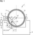
- FIG. 1 shows a schematic representation of a tube mill 2 as used for example for grinding of ore.
- the tube mill 2 has, a frame body 4, a circular cylindrical Milling tube 6 and an assembly 8 with a drive device 10, a braking device 12 (hidden by the drive device 10), a detection device 14 and a control device 16 on.
- the grinding tube 6 is rotatably mounted about an axis of rotation 18 in the frame body 4 and shown for better representation in a section.
- the grinding tube 6 has an inner wall 20.
- An adhesive charge 22 is located inside the grinding tube 6 and adheres to its inner wall 20.
- the adhering charge 22 or the grinding tube 6 are located in a rotational position 28 rotated by an angle of rotation 26 from an equilibrium position 24.
- a weight force 30 acts, which engages in a center of gravity 32 of the adhering charge 22.
- the weight force 30 causes a restoring moment about the axis of rotation 18.
- the drive device 10 drives the grinding tube 6 in a rotating manner.
- a non-adherent charge (not shown here) is crushed by impact, compression and shear forces transmitted between the charge itself, the inner wall 20 and possibly existing ball or cylinder bodies (grinding bodies). If the grinding operation of the tube mill 2 is interrupted for a sufficiently long period of time, it may, as described in the introduction to the in FIG. 1 shown adhesion of the charge on the inner wall 20 of the grinding tube 6 come.
- a certain rotational position for example a rotational position in the absolute value range of 90 ° to 180 °
- the angle of rotation which can lead to a collapse of the adhesive charge 22 is, inter alia, a charge property 34, for example, a level of the grinding tube 6 or a material property of the adhesive charge 22 dependent.
- the determination device 14 is equipped to determine the current rotation angle 26 or the current rotation position 28 and / or a rotational angular velocity 36 and / or a rotational angular acceleration 38 of the grinding tube 6.
- the detection device has a Polradgeber 15, which, as in FIG. 1 shown, not necessarily an integral part of the detection means must be, but may also be arranged separately from this.
- the braking device 12 is prepared in such a way that the grinding tube 6 can be braked as a function of the rotational angular velocity 36 and / or the rotational position 28 or the rotational angle 26.
- the brake device 12 is prepared for transmitting a brake pressure and / or a braking force and / or a braking torque to the grinding tube 6.
- the brake device 12 is prepared in such a way that the brake pressure and / or the braking force and / or the braking torque can be controlled or regulated. That the brake device 12 is prepared for activation by the control device 16.
- the control device 16 is prepared to control the brake pressure and / or the braking force and / or the braking torque depending on the rotational angular velocity 36 and / or the charge property 34 and / or the rotational angular acceleration 38 of the grinding tube 6.
- the driving device 10 moves the grinding tube 6 from the equilibrium position 24 to the rotational position 28, wherein the rotational position 28 can be dependent on the charging property 34.
- the driven rotation can also take place counter to the direction of rotation shown in FIG.
- the only decisive factor is the absolute value of the angle of rotation 26.
- the grinding tube 6 rotates without drive (automatically) due to the weight force 30 or the restoring moment resulting from the weight force 30 and the axis of rotation 18 in the direction of the equilibrium position 24 against the drive-related rotation.
- the determination device 14 determines in particular during the automatic rotation of the grinding tube 6 from the rotational position 28 the adjusting rotational angle 26 and / or the rotational angular velocity 36 and / or the rotational angular acceleration 38 of the grinding tube 6.
- the control device 16 controls the brake pressure or the braking force or the braking torque of the braking device 12 to the grinding pipe 6, such that it comes to a targeted deceleration of the grinding tube 6.
- an inertia force of the adhering charge 22 acts in a releasing manner on the adhering charge 22, so that advantageously the adhesive charge 22 is released from the inner wall 20 of the grinding tube 6.
- the grinding tube 6 is braked in particular in a dependence of the charge property 34. That For example, depending on the charge characteristic 34, the braking device 12 brakes the grinding tube as quickly as possible to a standstill or with a predefinable rotational angular acceleration 38 or predefinable delay 48.
- the predetermined delay 39 can be based on a mechanical stress limit of the tube mill 2. It can thus be ensured that no mechanical overloading of the brake device 12 or the tube mill 2 occurs due to excessively slow braking.
- the process can be repeated until the grinding tube 6 has reached the equilibrium position 24 or until it has reached its weight 32 generated restoring torque is no longer sufficient to enable the grinding tube 6 in an automatic rotation.
- the grinding tube 6 can again in the rotational position 28, preferably in a further rotated rotational position, rotated and the further process steps for releasing the adhesive charge 22 can be run through again.
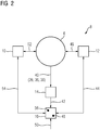
- FIG. 2 shows a schematic structure of a control arrangement 8 for releasing an adhesive charge 22 from an inner wall 20 of a grinding tube 6 (20, 22 see FIG. 1 ).
- the arrangement 8 has a drive device 10, a brake device 12, a determination device 14 and a control device 16.
- the determining device 14 determines at least one movement state variable 40 of the grinding tube 6.
- the at least one movement state variable 40 or the movement state variables 40 are preferably a rotation angle 26 and / or a rotational angular velocity 36 and / or a rotational angular acceleration 38, which takes the grinding tube 6 under an automatic gravitational rotation.
- a value of the at least one movement state variable 40 is transmitted to the control device 16 as a measurement signal 42.
- control device 16 controls the braking device 12 via a control signal 44.
- the brake device 12 brakes the grinding tube 6 via an action of a braking torque 46 (also: brake pressure, force) targeted from, the braking torque 46 in a function of the determined by the detection means 14 movement state variable 40, preferably the rotational angular acceleration 38, can be controlled or at least controlled.
- a braking torque 46 also: brake pressure, force
- a predefinable delay 48 is stored as a date or a value in the control device 16.
- the predeterminable delay 48 may be a temporally constant or time varying value which depends, in particular, on a charge property 34 of the adhered charge 22 (see FIGS FIG. 1 ).
- the charge characteristic 34 is input to or detected by the controller 16 in the form of an input value 50, which may also be a set of values.
- the input value 50 preferably refers to material-specific properties of the adhering charge 22 and / or a degree of filling of the grinding tube 6.
- the braking device 14 brakes the grinding pipe in such a way or is controlled by the control device 16 via the control signal 44 such that the predefinable delay 48 is not exceeded (at an upper limit value) or at least reached (at a lower limit value).
- the grinding pipe 6 is rotated by an effected by the drive device 10 drive torque 52 (also: driving force) in an appropriate rotational position.
- the rotation takes place, as described above, counter to a restoring moment of the adhesive charge 22 and is controlled by the control device 16 via a control signal 54.
- the control of the drive device 10 by the control device is preferably carried out as a function of the charge characteristic 34 of the adhesive charge 22, that is, as a function of the input value 50. That is, the assumed rotational position is determined as a function of the input value 50 or otherwise stored as a predetermined rotational position 56 in the control device 16.
- FIG. 3 shows a diagram with a schematic progression of a rotation angle 26 (ordinate [-]) of a grinding tube 6 over time 58 (abscissa [s]) during release of an adhering charge 22 from an inner wall 20 of a grinding tube 6 (FIGS. 6, 20, 22) FIG. 1 ).
- corresponding courses of a drive activity 60 (ordinate [-]) and a brake activity 62 (ordinate [-]) are shown over the time 58, respectively, with the three time axes shown being identical.
- the grinding tube rotates automatically, as explained above due to the weight of the adhering charge, against the previously caused by the drive activity 68 rotation. This results in an increase in the angular velocity.
- a braking activity 76 At a point in time 74, an abrupt braking of the grinding tube is brought about by a braking activity 76, whereby the grinding tube comes to a standstill in a rotational position 78.
- a braking torque 46 (see FIG. FIG. 2 ) on the grinding tube 6 (see. FIG. 1 . 2 ), wherein the explicit course of the braking torque 46 is not reproduced for reasons of clarity representability at this point.
- the braking activity 76 is terminated at a time 80, whereupon the grinding tube 6 is again automatically put into rotation and accelerated.
- the ascertainable rotational angular acceleration is lower in comparison to the rotational angular acceleration of the original reverse rotational movement at the time 72 as a result of the now reduced restoring torque of the adhesive charge 22, which is now reduced by the lever arm.
- a renewed braking activity 84 causes a further abrupt deceleration of the grinding tube 6, wherein the grinding tube comes to a standstill in a rotational position 86.
- the braking activity 84 is terminated at a point in time 88, wherein the grinding tube does not automatically set in rotation again, but remains in the rotational position 86 with the charge now dissolved.
- FIG. 4 shows a further diagram with a schematic course of a rotation angle 26 (ordinate [-]) of a grinding tube 6 over the time 58 (abscissa [s]) during release of an adhesive charge 22 from an inner wall 20 of a grinding tube 6 (6, 20, 22 please refer FIG. 1 ).
- corresponding courses of a driving activity 60 (ordinate [-]) and a braking activity 62 (ordinate [-]) are again shown over the time 58, respectively, with the three time axes shown being identical.
- the grinding tube 6 rotates automatically, as explained above due to the weight of the adhering charge, against the previously caused by the drive activity 94 rotation. This results in an increase in the angular velocity.
- braking of the grinding tube 6 is achieved by a braking activity 102 until reaching a predefinable deceleration 48 (cf. FIG. 2 ), wherein the grinding tube 6 comes to a stop in a rotational position 104. That is, the grinding tube 6 is in contrast to the in FIG. 3 illustrated embodiment is not abrupt, but braked well dosed.
- the braking activity 102 is at a rotational position 106 and preferably in a dependence of the determined at this time rotational angular velocity 36 (see. FIG. 1 . 2 ).
- the braking activity 102 is terminated at a point in time 108, whereupon the grinding tube 5 again automatically sets in rotation until the time 110 again the equilibrium position 24 (see. FIG. 1 ) or the rotational position 90 is achieved without loosening the adhesive charge 22.
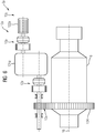
- FIG. 5 1 shows a schematic representation of a typical drive device 10 for the driven turning of a grinding tube 6.
- the drive device 10 has a main drive 122, a main gear 124, a power take-off 126, a sub-transmission 128, two auxiliary clutches 130 and a main clutch 132.
- the braking device 12 is arranged between the auxiliary drive 126 and the auxiliary transmission 128, wherein the braking device 12 can also be arranged at a different position or structurally separated from the drive device 10.
- the drive device 10 operates on a sprocket 134, which may be arranged on a circumference of the grinding tube 6.
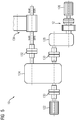
- FIG. 6 shows a schematic representation of a tube mill 2a in plan view.
- the tube mill 2a has a grinding tube 6, which is rotatably mounted about a rotation axis 18, a drive device 10a with a main drive 122a and a main gear 124a.
- the drive device 10a operates on the ring gear 134.
- the tube mill 2a also has a plurality of braking devices 12a. These are mounted between the main drive 122a and the main gear 124a, the output side of the main gear 124a and the ring gear 134th
- FIG. 7 shows a schematic representation of another tube mill 2b in plan view.
- the tube mill 2b has a grinding tube 6, which is rotatably mounted about an axis of rotation 18, a drive device 10b with a main drive 122b, a main gear 124b, a secondary drive 126a and a secondary gear 128a.
- the drive device 10b operates on the ring gear 134.
- the tube mill 2b also has a plurality of braking devices 12b. These are mounted between the main drive 122b and the main transmission 124b, on the output side on the main transmission 124b, between the auxiliary drive 126a and the subtransmission 128a, on the output side on the subtransmission 128a and on the toothed rim 134.
- FIG. 8 shows a schematic representation of another tube mill 2c in plan view.
- the tube mill 2b has a grinding tube 6, which is rotatably mounted about a rotational axis 18, a drive device 10b with a main drive 122c, a main gear 124c, a secondary drive 126b and a secondary gear 128b.
- the main gear 124c of the drive device 10b operates directly on the ring gear 134.
- the tube mill 2c also has a plurality of braking devices 12c. These are mounted between the main drive 122b and the main gear 124b, between the power take-off 126a and the sub-transmission 128a, the power take-off 126ba and the ring gear 134.
Landscapes
- Engineering & Computer Science (AREA)
- Food Science & Technology (AREA)
- Crushing And Grinding (AREA)
- Constituent Portions Of Griding Lathes, Driving, Sensing And Control (AREA)
- Grinding Of Cylindrical And Plane Surfaces (AREA)
- Braking Arrangements (AREA)
- Finish Polishing, Edge Sharpening, And Grinding By Specific Grinding Devices (AREA)
- Disintegrating Or Milling (AREA)
Claims (15)
- Procédé pour détacher une charge (22) adhérente d'une paroi (20) intérieure d'un tube (6) broyeur,
caractérisé en ce que- on fait tourner en sens inverse, sans entraînement, par la force (30) pondérale de la charge (22) adhérente, le tube (6) broyeur, à partir d'une position (28) en rotation prise et pouvant être donnée à l'avance, au moins une grandeur (40) d'état de mouvement du tube (6) broyeur étant déterminée et- on freine, pendant la rotation en sens inverse, le tube (6) broyeur, en fonction de la au moins une grandeur (40) d'état de mouvement déterminée pour détacher la charge (22) adhérente de la paroi (20) intérieure du tube (6) broyeur. - Procédé suivant la revendication 1,
caractérisé en ce que l'on atteint la position (28) en rotation prise et pouvant être donnée à l'avance par une rotation entraînée en utilisant un moyen d'entraînement du tube (6) broyeur. - Procédé suivant l'une des revendications précédentes,
caractérisé en ce que la position (28) en rotation prise et pouvant être donnée à l'avance du tube (6) broyeur est donnée à l'avance par un angle (26) de rotation déterminé en fonction d'une propriété (34) de la charge. - Procédé suivant l'une des revendications précédentes,
caractérisé en ce que la position (28) en rotation prise du tube (6) broyeur est donnée à l'avance par un angle (26) de rotation d'une valeur comprise entre 40° et 90°, à partir d'une position (24) d'équilibre stable. - Procédé suivant l'une des revendications précédentes,
caractérisé en ce que la au moins une grandeur (40) d'état de mouvement déterminée est un angle (26) de rotation et/ou une vitesse (36) angulaire de rotation et/ou une accélération (38) angulaire de rotation du tube (6) broyeur. - Procédé suivant l'une des revendications précédentes,
caractérisé en ce que l'on freine le tube (6) broyeur pendant la rotation en sens inverse au moins une fois jusqu'à l'état d'arrêt. - Procédé suivant l'une des revendications précédentes,
caractérisé en ce que l'on freine le tube (6) broyeur pendant la rotation en sens inverse au moins une fois à une décélération (48) pouvant être donnée à l'avance. - Procédé suivant la revendication 7,
caractérisé en ce que l'on détermine la décélération (48) pouvant être donnée à l'avance en fonction d'une propriété (34) de la charge. - Procédé suivant la revendication 7,
caractérisé en ce que l'on détermine la décélération (48) pouvant être donnée à l'avance en fonction d'une limite de sollicitation mécanique du tube (6) broyeur. - Agencement (8) pour détacher une charge adhérente d'une paroi (20) intérieur d'un tube (6) broyeur,
caractérisé par- un dispositif (44) de détermination conçu pour pouvoir déterminer au moins une grandeur (40) d'état de mouvement du tube (6) broyeur,- une unité (10) d'entraînement conçue pour entraîner en rotation le tube (6) broyeur,- un dispositif (12) de freinage conçu pour freiner le tube (6) broyeur à une décélération (48) pouvant être donnée à l'avance et- un dispositif (16) de commande conçu pour commander le dispositif (12) de frein en fonction de la au moins une grandeur (40) d'état de mouvement déterminée et pour commander l'unité (10) d'entraînement afin d'interrompre une activité (68) d'entraînement de l'unité (10) d'entraînement à une position (28) en rotation prise et pouvant être donnée à l'avance du tube (6) broyeur. - Agencement (8) suivant la revendication 10,
caractérisé en ce que- le dispositif (10) d'entraînement est conçu pour mettre, par entraînement, le tube (6) broyeur en une position (28) en rotation pouvant être donnée à l'avance, le dispositif (16) de commande étant destiné à commander le dispositif (10) d'entraînement en fonction de la au moins une grandeur (40) d'état de mouvement déterminée et/ou d'une propriété (34) de la charge. - Agencement (8) suivant la revendication 10,
caractérisé par- une unité de détection destinée à déterminer un détachement de la charge (22) adhérente de la paroi (20) intérieure du tube (6) broyeur en fonction d'au moins une grandeur (40) d'état de mouvement du tube (6) broyeur. - Agencement (8) suivant la revendication 10,
caractérisé en ce que le dispositif (12) de frein a un frein mécanique, notamment un frein à tambour, de préférence un frein à disque. - Agencement (8) suivant la revendication 10,
caractérisé en ce que le dispositif (14) de détermination a un indicateur (15) à roue polaire. - Tube (2) broyeur ayant un agencement (8) suivant l'une des revendications 10 à 12.
Priority Applications (3)
| Application Number | Priority Date | Filing Date | Title |
|---|---|---|---|
| PL15711688T PL3094409T3 (pl) | 2014-03-24 | 2015-03-12 | Oddzielanie przywierającego wsadu od wewnętrznej ściany rury młyna |
| EP15711688.0A EP3094409B1 (fr) | 2014-03-24 | 2015-03-12 | Détachement d'une charge adhérant à la paroi intérieure d'un tube broyeur |
| NO15711688A NO3094409T3 (fr) | 2014-03-24 | 2015-03-12 |
Applications Claiming Priority (3)
| Application Number | Priority Date | Filing Date | Title |
|---|---|---|---|
| EP14161257.2A EP2923767A1 (fr) | 2014-03-24 | 2014-03-24 | Détachement d'une charge adhérant à la paroi intérieure d'un tube broyeur |
| EP15711688.0A EP3094409B1 (fr) | 2014-03-24 | 2015-03-12 | Détachement d'une charge adhérant à la paroi intérieure d'un tube broyeur |
| PCT/EP2015/055212 WO2015144444A1 (fr) | 2014-03-24 | 2015-03-12 | Détachement d'une charge adhérant à une paroi intérieure d'un tube de broyage |
Publications (2)
| Publication Number | Publication Date |
|---|---|
| EP3094409A1 EP3094409A1 (fr) | 2016-11-23 |
| EP3094409B1 true EP3094409B1 (fr) | 2018-03-07 |
Family
ID=50389815
Family Applications (2)
| Application Number | Title | Priority Date | Filing Date |
|---|---|---|---|
| EP14161257.2A Withdrawn EP2923767A1 (fr) | 2014-03-24 | 2014-03-24 | Détachement d'une charge adhérant à la paroi intérieure d'un tube broyeur |
| EP15711688.0A Active EP3094409B1 (fr) | 2014-03-24 | 2015-03-12 | Détachement d'une charge adhérant à la paroi intérieure d'un tube broyeur |
Family Applications Before (1)
| Application Number | Title | Priority Date | Filing Date |
|---|---|---|---|
| EP14161257.2A Withdrawn EP2923767A1 (fr) | 2014-03-24 | 2014-03-24 | Détachement d'une charge adhérant à la paroi intérieure d'un tube broyeur |
Country Status (20)
| Country | Link |
|---|---|
| US (1) | US10543490B2 (fr) |
| EP (2) | EP2923767A1 (fr) |
| JP (1) | JP6362708B2 (fr) |
| KR (1) | KR101835256B1 (fr) |
| CN (1) | CN106102919B (fr) |
| AR (1) | AR099809A1 (fr) |
| AU (1) | AU2015238729B2 (fr) |
| BR (1) | BR112016021422B1 (fr) |
| CA (1) | CA2943579C (fr) |
| CL (1) | CL2016002253A1 (fr) |
| CU (1) | CU24447B1 (fr) |
| EA (1) | EA031784B1 (fr) |
| MX (1) | MX377241B (fr) |
| MY (1) | MY179891A (fr) |
| NO (1) | NO3094409T3 (fr) |
| PE (1) | PE20161162A1 (fr) |
| PH (1) | PH12016501888A1 (fr) |
| PL (1) | PL3094409T3 (fr) |
| UA (1) | UA116593C2 (fr) |
| WO (1) | WO2015144444A1 (fr) |
Families Citing this family (12)
| Publication number | Priority date | Publication date | Assignee | Title |
|---|---|---|---|---|
| EP3097979A1 (fr) * | 2015-05-28 | 2016-11-30 | ABB Technology AG | Procédé permettant de déterminer un angle de levage et procédé de positionnement d'un broyeur |
| CN105478201B (zh) * | 2015-12-24 | 2017-11-10 | 山东理工大学 | 推力电机式多仓管磨机胀肚检测装置及预胀肚调控方法 |
| EP3269453A1 (fr) * | 2016-07-15 | 2018-01-17 | Siemens Aktiengesellschaft | Procédé de démarrage d'un broyeur tubulaire |
| CA3006100A1 (fr) * | 2017-05-25 | 2018-11-25 | Vermeer Manufacturing Company | Disposition d'entrainement rotatif destine a la rotation d'un recipient |
| EP3453458A1 (fr) * | 2017-09-06 | 2019-03-13 | Siemens Aktiengesellschaft | Procédé et dispositif de détachement d'une charge adhérant à la face intérieure d'un tube de broyage d'un broyeur tubulaire |
| KR102005889B1 (ko) * | 2018-11-08 | 2019-08-01 | 김형우 | 볼밀 회전드럼 |
| KR102173219B1 (ko) * | 2019-02-07 | 2020-11-03 | 주식회사 에코비젼21 | 주물사 분리장치의 라이너 회전속도 제어 방법 및 회전속도 제어 구조 |
| CN111359729B (zh) * | 2020-03-17 | 2021-06-18 | 中信重工机械股份有限公司 | 一种磨机物料板结检测系统 |
| CN112090521B (zh) * | 2020-09-25 | 2021-12-31 | 淄博鲁兴铝基新材料有限公司 | 一种纳米材料制备用球磨机 |
| JP7637871B2 (ja) * | 2020-11-24 | 2025-03-03 | 株式会社ナガオシステム | 回転装置および微粒子作製方法 |
| TW202228847A (zh) * | 2020-10-09 | 2022-08-01 | 日商三菱綜合材料股份有限公司 | 旋轉裝置以及微粒子製作方法 |
| JP7661614B2 (ja) * | 2022-03-30 | 2025-04-14 | 株式会社Tmeic | 検出装置および検出システム |
Family Cites Families (20)
| Publication number | Priority date | Publication date | Assignee | Title |
|---|---|---|---|---|
| US3944189A (en) * | 1973-11-28 | 1976-03-16 | Albert Singleton | Door opening and closing apparatus for tumbling barrel |
| JPS5345783A (en) | 1976-10-06 | 1978-04-24 | Kawasaki Heavy Ind Ltd | Method for assembling rotary cylinder supported by bearings at both ends thereof |
| JPH02245249A (ja) | 1989-03-17 | 1990-10-01 | Agency Of Ind Science & Technol | 多軸傾斜軸ボールミル |
| JP3155803B2 (ja) | 1992-02-06 | 2001-04-16 | バブコック日立株式会社 | 湿式ミルの運転方法 |
| JP2604297B2 (ja) | 1992-03-26 | 1997-04-30 | 新和プラント機工株式会社 | 破砕装置 |
| JP2837791B2 (ja) | 1993-05-18 | 1998-12-16 | 杉山重工株式会社 | 円錐型ボールミル |
| JP3165565B2 (ja) | 1993-08-20 | 2001-05-14 | 三菱重工業株式会社 | 横型乾式ミルの付着粉体除去方法 |
| CN2198974Y (zh) | 1994-08-13 | 1995-05-31 | 刘邦沐 | 油压传动式球磨机 |
| JPH08131858A (ja) | 1994-11-07 | 1996-05-28 | Mitsubishi Heavy Ind Ltd | 横型超微粉砕ミルの再起動運転方法及び横型超微粉砕ミル |
| CN2254378Y (zh) | 1996-03-19 | 1997-05-21 | 济南重机集团公司 | 新型球磨机慢速传动装置 |
| DE10123821A1 (de) | 2000-06-02 | 2001-12-20 | Ibm | Geschaltete Ethernet-Netzwerke |
| US7017841B2 (en) | 2001-09-17 | 2006-03-28 | Ehrenfried Albert Tirschler | Angle-based method and device for protecting a rotating component |
| JP2005111401A (ja) | 2003-10-09 | 2005-04-28 | Earth Technica:Kk | 粉体処理装置 |
| DE102004015057A1 (de) | 2004-03-25 | 2005-10-20 | Siemens Ag | Verfahren, Steuervorrichtung und Antriebsvorrichtung zum Lösen einer festgeklebten Ladung von der Innenwand eines Mahlrohrs |
| CN2803664Y (zh) | 2005-07-20 | 2006-08-09 | 郑州豫兴氮氧结合耐火材料有限公司 | 自动拨转连续挤球装置 |
| US8020792B2 (en) * | 2005-12-27 | 2011-09-20 | Metso Minerals Industries, Inc. | Locked charge detector |
| JP2008022075A (ja) | 2006-07-10 | 2008-01-31 | Yamaha Corp | レイヤ2スイッチおよびネットワーク監視システム |
| EP2347828A1 (fr) * | 2010-01-21 | 2011-07-27 | ABB Schweiz AG | Procédé et appareil pour détacher une charge collée dans un broyeur à tambour |
| DE102011004416B4 (de) * | 2011-02-18 | 2017-07-20 | Siemens Aktiengesellschaft | Antriebssystem für eine Kugelmühle und Verfahren zum Betreiben einer Kugelmühle |
| US9025533B1 (en) | 2014-09-29 | 2015-05-05 | RG Nets, Inc. | System and method for dynamic VLAN assignment |
-
2014
- 2014-03-24 EP EP14161257.2A patent/EP2923767A1/fr not_active Withdrawn
-
2015
- 2015-03-12 EP EP15711688.0A patent/EP3094409B1/fr active Active
- 2015-03-12 CU CU2016000126A patent/CU24447B1/es unknown
- 2015-03-12 BR BR112016021422-6A patent/BR112016021422B1/pt active IP Right Grant
- 2015-03-12 EA EA201691905A patent/EA031784B1/ru not_active IP Right Cessation
- 2015-03-12 WO PCT/EP2015/055212 patent/WO2015144444A1/fr not_active Ceased
- 2015-03-12 NO NO15711688A patent/NO3094409T3/no unknown
- 2015-03-12 US US15/128,366 patent/US10543490B2/en not_active Expired - Fee Related
- 2015-03-12 MX MX2016012239A patent/MX377241B/es active IP Right Grant
- 2015-03-12 CN CN201580013641.3A patent/CN106102919B/zh active Active
- 2015-03-12 CA CA2943579A patent/CA2943579C/fr active Active
- 2015-03-12 MY MYPI2016703406A patent/MY179891A/en unknown
- 2015-03-12 PE PE2016001579A patent/PE20161162A1/es unknown
- 2015-03-12 PL PL15711688T patent/PL3094409T3/pl unknown
- 2015-03-12 AU AU2015238729A patent/AU2015238729B2/en active Active
- 2015-03-12 KR KR1020167029048A patent/KR101835256B1/ko not_active Expired - Fee Related
- 2015-03-12 JP JP2016558754A patent/JP6362708B2/ja not_active Expired - Fee Related
- 2015-03-20 AR ARP150100845A patent/AR099809A1/es active IP Right Grant
- 2015-12-03 UA UAA201609731A patent/UA116593C2/uk unknown
-
2016
- 2016-09-06 CL CL2016002253A patent/CL2016002253A1/es unknown
- 2016-09-23 PH PH12016501888A patent/PH12016501888A1/en unknown
Also Published As
| Publication number | Publication date |
|---|---|
| UA116593C2 (uk) | 2018-04-10 |
| CA2943579A1 (fr) | 2015-10-01 |
| US10543490B2 (en) | 2020-01-28 |
| KR101835256B1 (ko) | 2018-03-06 |
| EP3094409A1 (fr) | 2016-11-23 |
| CU24447B1 (es) | 2019-10-04 |
| EP2923767A1 (fr) | 2015-09-30 |
| PH12016501888B1 (en) | 2016-12-19 |
| CN106102919A (zh) | 2016-11-09 |
| NO3094409T3 (fr) | 2018-08-04 |
| JP2017513694A (ja) | 2017-06-01 |
| AR099809A1 (es) | 2016-08-17 |
| MY179891A (en) | 2020-11-18 |
| AU2015238729B2 (en) | 2017-07-20 |
| CA2943579C (fr) | 2018-12-04 |
| WO2015144444A1 (fr) | 2015-10-01 |
| CN106102919B (zh) | 2019-05-10 |
| BR112016021422A2 (fr) | 2017-08-15 |
| BR112016021422B1 (pt) | 2021-10-13 |
| CU20160126A7 (es) | 2017-05-10 |
| JP6362708B2 (ja) | 2018-07-25 |
| AU2015238729A1 (en) | 2016-09-29 |
| EA201691905A1 (ru) | 2016-12-30 |
| PE20161162A1 (es) | 2016-11-23 |
| KR20160134809A (ko) | 2016-11-23 |
| CL2016002253A1 (es) | 2016-12-30 |
| EA031784B1 (ru) | 2019-02-28 |
| PH12016501888A1 (en) | 2016-12-19 |
| MX2016012239A (es) | 2017-01-19 |
| PL3094409T3 (pl) | 2018-08-31 |
| MX377241B (es) | 2025-03-07 |
| US20180169663A1 (en) | 2018-06-21 |
Similar Documents
| Publication | Publication Date | Title |
|---|---|---|
| EP2923767A1 (fr) | Détachement d'une charge adhérant à la paroi intérieure d'un tube broyeur | |
| EP2887535B1 (fr) | Système d'entraînement et de commande pour portes relevables | |
| EP2791427B1 (fr) | Dispositif de freinage de mécanismes rotatifs et/ou pivotants, procédé de commande d'un tel dispositif et engin de travail pourvu d'un tel dispositif de freinage | |
| DE3404018C2 (fr) | ||
| EP2315943B1 (fr) | Dispositif de réglage destiné à régler la position angulaire du rotor d'une installation éolienne | |
| EP2945899B1 (fr) | Protection contre la surcharge pour systèmes de portiques à conteneurs | |
| EP2353724B1 (fr) | Procédé, dispositif de commande et dispositif d'entraînement destinés à détacher un chargement collé à la paroi intérieure d'un tube broyeur | |
| DE102015218300C5 (de) | Motorbetriebener Kranantrieb und Verfahren zu dessen Betrieb | |
| EP2389509B1 (fr) | Installation de production d'energie stationnaire dotee d'un dispositif de freinage | |
| WO2012143342A2 (fr) | Centrifugeuse et procédé pour contrôler un couple | |
| WO2007147650A1 (fr) | Frein de rotor à régulation | |
| DE102010013095A1 (de) | Pelletiereinrichtung | |
| EP3124342A2 (fr) | Procede de commande d'un ou plusieurs freins d'un vehicule | |
| DE102010009857A1 (de) | Verfahren zum Abbremsen einer Windenergieanlage und Abbremsvorrichtung zur Durchführung des Verfahrens | |
| DE102020124135A1 (de) | Verfahren und Vorrichtung zum Steuern eines Bremsvorgangs in einem Antriebsstrang | |
| DE102013206002A1 (de) | Verfahren und Einrichtung zum Ein- und/oder Auskoppeln eines Getriebe-Hilfsantriebs, Windenergieanlage | |
| CN201746124U (zh) | 盘式拉紧锥轴滑键式装置 | |
| DE202010004261U1 (de) | Pelletiereinrichtung | |
| DE19946856A1 (de) | Verfahren zum Ansteuern eines Antriebssystems eines Fahrzeugs und Antriebssystem |
Legal Events
| Date | Code | Title | Description |
|---|---|---|---|
| PUAI | Public reference made under article 153(3) epc to a published international application that has entered the european phase |
Free format text: ORIGINAL CODE: 0009012 |
|
| 17P | Request for examination filed |
Effective date: 20160816 |
|
| AK | Designated contracting states |
Kind code of ref document: A1 Designated state(s): AL AT BE BG CH CY CZ DE DK EE ES FI FR GB GR HR HU IE IS IT LI LT LU LV MC MK MT NL NO PL PT RO RS SE SI SK SM TR |
|
| AX | Request for extension of the european patent |
Extension state: BA ME |
|
| DAV | Request for validation of the european patent (deleted) | ||
| RAX | Requested extension states of the european patent have changed |
Extension state: BA Payment date: 20160816 |
|
| RAP1 | Party data changed (applicant data changed or rights of an application transferred) |
Owner name: SIEMENS AKTIENGESELLSCHAFT |
|
| GRAP | Despatch of communication of intention to grant a patent |
Free format text: ORIGINAL CODE: EPIDOSNIGR1 |
|
| INTG | Intention to grant announced |
Effective date: 20171026 |
|
| GRAS | Grant fee paid |
Free format text: ORIGINAL CODE: EPIDOSNIGR3 |
|
| GRAA | (expected) grant |
Free format text: ORIGINAL CODE: 0009210 |
|
| AK | Designated contracting states |
Kind code of ref document: B1 Designated state(s): AL AT BE BG CH CY CZ DE DK EE ES FI FR GB GR HR HU IE IS IT LI LT LU LV MC MK MT NL NO PL PT RO RS SE SI SK SM TR |
|
| AX | Request for extension of the european patent |
Extension state: BA |
|
| REG | Reference to a national code |
Ref country code: GB Ref legal event code: FG4D Free format text: NOT ENGLISH |
|
| REG | Reference to a national code |
Ref country code: CH Ref legal event code: EP Ref country code: AT Ref legal event code: REF Ref document number: 975982 Country of ref document: AT Kind code of ref document: T Effective date: 20180315 |
|
| REG | Reference to a national code |
Ref country code: DE Ref legal event code: R096 Ref document number: 502015003296 Country of ref document: DE |
|
| REG | Reference to a national code |
Ref country code: IE Ref legal event code: FG4D Free format text: LANGUAGE OF EP DOCUMENT: GERMAN |
|
| REG | Reference to a national code |
Ref country code: RO Ref legal event code: EPE |
|
| REG | Reference to a national code |
Ref country code: SE Ref legal event code: TRGR |
|
| REG | Reference to a national code |
Ref country code: NL Ref legal event code: MP Effective date: 20180307 |
|
| REG | Reference to a national code |
Ref country code: NO Ref legal event code: T2 Effective date: 20180307 |
|
| REG | Reference to a national code |
Ref country code: LT Ref legal event code: MG4D |
|
| PG25 | Lapsed in a contracting state [announced via postgrant information from national office to epo] |
Ref country code: FI Free format text: LAPSE BECAUSE OF FAILURE TO SUBMIT A TRANSLATION OF THE DESCRIPTION OR TO PAY THE FEE WITHIN THE PRESCRIBED TIME-LIMIT Effective date: 20180307 Ref country code: ES Free format text: LAPSE BECAUSE OF FAILURE TO SUBMIT A TRANSLATION OF THE DESCRIPTION OR TO PAY THE FEE WITHIN THE PRESCRIBED TIME-LIMIT Effective date: 20180307 Ref country code: HR Free format text: LAPSE BECAUSE OF FAILURE TO SUBMIT A TRANSLATION OF THE DESCRIPTION OR TO PAY THE FEE WITHIN THE PRESCRIBED TIME-LIMIT Effective date: 20180307 Ref country code: LT Free format text: LAPSE BECAUSE OF FAILURE TO SUBMIT A TRANSLATION OF THE DESCRIPTION OR TO PAY THE FEE WITHIN THE PRESCRIBED TIME-LIMIT Effective date: 20180307 Ref country code: CY Free format text: LAPSE BECAUSE OF FAILURE TO SUBMIT A TRANSLATION OF THE DESCRIPTION OR TO PAY THE FEE WITHIN THE PRESCRIBED TIME-LIMIT Effective date: 20180307 |
|
| PG25 | Lapsed in a contracting state [announced via postgrant information from national office to epo] |
Ref country code: LV Free format text: LAPSE BECAUSE OF FAILURE TO SUBMIT A TRANSLATION OF THE DESCRIPTION OR TO PAY THE FEE WITHIN THE PRESCRIBED TIME-LIMIT Effective date: 20180307 Ref country code: RS Free format text: LAPSE BECAUSE OF FAILURE TO SUBMIT A TRANSLATION OF THE DESCRIPTION OR TO PAY THE FEE WITHIN THE PRESCRIBED TIME-LIMIT Effective date: 20180307 |
|
| PG25 | Lapsed in a contracting state [announced via postgrant information from national office to epo] |
Ref country code: MT Free format text: LAPSE BECAUSE OF FAILURE TO SUBMIT A TRANSLATION OF THE DESCRIPTION OR TO PAY THE FEE WITHIN THE PRESCRIBED TIME-LIMIT Effective date: 20180307 |
|
| REG | Reference to a national code |
Ref country code: DE Ref legal event code: R119 Ref document number: 502015003296 Country of ref document: DE |
|
| PG25 | Lapsed in a contracting state [announced via postgrant information from national office to epo] |
Ref country code: EE Free format text: LAPSE BECAUSE OF FAILURE TO SUBMIT A TRANSLATION OF THE DESCRIPTION OR TO PAY THE FEE WITHIN THE PRESCRIBED TIME-LIMIT Effective date: 20180307 Ref country code: IT Free format text: LAPSE BECAUSE OF FAILURE TO SUBMIT A TRANSLATION OF THE DESCRIPTION OR TO PAY THE FEE WITHIN THE PRESCRIBED TIME-LIMIT Effective date: 20180307 Ref country code: AL Free format text: LAPSE BECAUSE OF FAILURE TO SUBMIT A TRANSLATION OF THE DESCRIPTION OR TO PAY THE FEE WITHIN THE PRESCRIBED TIME-LIMIT Effective date: 20180307 Ref country code: NL Free format text: LAPSE BECAUSE OF FAILURE TO SUBMIT A TRANSLATION OF THE DESCRIPTION OR TO PAY THE FEE WITHIN THE PRESCRIBED TIME-LIMIT Effective date: 20180307 |
|
| REG | Reference to a national code |
Ref country code: CH Ref legal event code: PL |
|
| PG25 | Lapsed in a contracting state [announced via postgrant information from national office to epo] |
Ref country code: SM Free format text: LAPSE BECAUSE OF FAILURE TO SUBMIT A TRANSLATION OF THE DESCRIPTION OR TO PAY THE FEE WITHIN THE PRESCRIBED TIME-LIMIT Effective date: 20180307 Ref country code: SK Free format text: LAPSE BECAUSE OF FAILURE TO SUBMIT A TRANSLATION OF THE DESCRIPTION OR TO PAY THE FEE WITHIN THE PRESCRIBED TIME-LIMIT Effective date: 20180307 |
|
| REG | Reference to a national code |
Ref country code: BE Ref legal event code: MM Effective date: 20180331 |
|
| REG | Reference to a national code |
Ref country code: IE Ref legal event code: MM4A |
|
| PG25 | Lapsed in a contracting state [announced via postgrant information from national office to epo] |
Ref country code: PT Free format text: LAPSE BECAUSE OF FAILURE TO SUBMIT A TRANSLATION OF THE DESCRIPTION OR TO PAY THE FEE WITHIN THE PRESCRIBED TIME-LIMIT Effective date: 20180709 Ref country code: LU Free format text: LAPSE BECAUSE OF NON-PAYMENT OF DUE FEES Effective date: 20180312 |
|
| PLBE | No opposition filed within time limit |
Free format text: ORIGINAL CODE: 0009261 |
|
| STAA | Information on the status of an ep patent application or granted ep patent |
Free format text: STATUS: NO OPPOSITION FILED WITHIN TIME LIMIT |
|
| PG25 | Lapsed in a contracting state [announced via postgrant information from national office to epo] |
Ref country code: IE Free format text: LAPSE BECAUSE OF NON-PAYMENT OF DUE FEES Effective date: 20180312 Ref country code: DK Free format text: LAPSE BECAUSE OF FAILURE TO SUBMIT A TRANSLATION OF THE DESCRIPTION OR TO PAY THE FEE WITHIN THE PRESCRIBED TIME-LIMIT Effective date: 20180307 Ref country code: DE Free format text: LAPSE BECAUSE OF NON-PAYMENT OF DUE FEES Effective date: 20181002 Ref country code: MC Free format text: LAPSE BECAUSE OF FAILURE TO SUBMIT A TRANSLATION OF THE DESCRIPTION OR TO PAY THE FEE WITHIN THE PRESCRIBED TIME-LIMIT Effective date: 20180307 |
|
| 26N | No opposition filed |
Effective date: 20181210 |
|
| PG25 | Lapsed in a contracting state [announced via postgrant information from national office to epo] |
Ref country code: BE Free format text: LAPSE BECAUSE OF NON-PAYMENT OF DUE FEES Effective date: 20180331 Ref country code: LI Free format text: LAPSE BECAUSE OF NON-PAYMENT OF DUE FEES Effective date: 20180331 Ref country code: SI Free format text: LAPSE BECAUSE OF FAILURE TO SUBMIT A TRANSLATION OF THE DESCRIPTION OR TO PAY THE FEE WITHIN THE PRESCRIBED TIME-LIMIT Effective date: 20180307 Ref country code: CH Free format text: LAPSE BECAUSE OF NON-PAYMENT OF DUE FEES Effective date: 20180331 |
|
| REG | Reference to a national code |
Ref country code: GR Ref legal event code: EP Ref document number: 20180401424 Country of ref document: GR Effective date: 20190225 |
|
| PG25 | Lapsed in a contracting state [announced via postgrant information from national office to epo] |
Ref country code: FR Free format text: LAPSE BECAUSE OF NON-PAYMENT OF DUE FEES Effective date: 20180507 |
|
| GBPC | Gb: european patent ceased through non-payment of renewal fee |
Effective date: 20190312 |
|
| PG25 | Lapsed in a contracting state [announced via postgrant information from national office to epo] |
Ref country code: GB Free format text: LAPSE BECAUSE OF NON-PAYMENT OF DUE FEES Effective date: 20190312 |
|
| PG25 | Lapsed in a contracting state [announced via postgrant information from national office to epo] |
Ref country code: TR Free format text: LAPSE BECAUSE OF FAILURE TO SUBMIT A TRANSLATION OF THE DESCRIPTION OR TO PAY THE FEE WITHIN THE PRESCRIBED TIME-LIMIT Effective date: 20180307 |
|
| PGFP | Annual fee paid to national office [announced via postgrant information from national office to epo] |
Ref country code: RO Payment date: 20200225 Year of fee payment: 6 Ref country code: GR Payment date: 20200304 Year of fee payment: 6 Ref country code: SE Payment date: 20200317 Year of fee payment: 6 Ref country code: BG Payment date: 20200323 Year of fee payment: 6 Ref country code: NO Payment date: 20200323 Year of fee payment: 6 |
|
| PGFP | Annual fee paid to national office [announced via postgrant information from national office to epo] |
Ref country code: CZ Payment date: 20200312 Year of fee payment: 6 |
|
| PG25 | Lapsed in a contracting state [announced via postgrant information from national office to epo] |
Ref country code: HU Free format text: LAPSE BECAUSE OF FAILURE TO SUBMIT A TRANSLATION OF THE DESCRIPTION OR TO PAY THE FEE WITHIN THE PRESCRIBED TIME-LIMIT; INVALID AB INITIO Effective date: 20150312 |
|
| PGFP | Annual fee paid to national office [announced via postgrant information from national office to epo] |
Ref country code: MK Payment date: 20200224 Year of fee payment: 6 |
|
| PG25 | Lapsed in a contracting state [announced via postgrant information from national office to epo] |
Ref country code: IS Free format text: LAPSE BECAUSE OF FAILURE TO SUBMIT A TRANSLATION OF THE DESCRIPTION OR TO PAY THE FEE WITHIN THE PRESCRIBED TIME-LIMIT Effective date: 20180707 |
|
| REG | Reference to a national code |
Ref country code: AT Ref legal event code: MM01 Ref document number: 975982 Country of ref document: AT Kind code of ref document: T Effective date: 20200312 |
|
| PG25 | Lapsed in a contracting state [announced via postgrant information from national office to epo] |
Ref country code: AT Free format text: LAPSE BECAUSE OF NON-PAYMENT OF DUE FEES Effective date: 20200312 |
|
| REG | Reference to a national code |
Ref country code: NO Ref legal event code: MMEP |
|
| PG25 | Lapsed in a contracting state [announced via postgrant information from national office to epo] |
Ref country code: CZ Free format text: LAPSE BECAUSE OF NON-PAYMENT OF DUE FEES Effective date: 20210312 |
|
| PG25 | Lapsed in a contracting state [announced via postgrant information from national office to epo] |
Ref country code: RO Free format text: LAPSE BECAUSE OF NON-PAYMENT OF DUE FEES Effective date: 20210312 |
|
| PG25 | Lapsed in a contracting state [announced via postgrant information from national office to epo] |
Ref country code: NO Free format text: LAPSE BECAUSE OF NON-PAYMENT OF DUE FEES Effective date: 20210331 Ref country code: BG Free format text: LAPSE BECAUSE OF NON-PAYMENT OF DUE FEES Effective date: 20210930 Ref country code: SE Free format text: LAPSE BECAUSE OF NON-PAYMENT OF DUE FEES Effective date: 20210313 |
|
| PG25 | Lapsed in a contracting state [announced via postgrant information from national office to epo] |
Ref country code: GR Free format text: LAPSE BECAUSE OF NON-PAYMENT OF DUE FEES Effective date: 20211008 |
|
| PGFP | Annual fee paid to national office [announced via postgrant information from national office to epo] |
Ref country code: PL Payment date: 20260226 Year of fee payment: 12 |