EP3094530B1 - Procédé et système pour évaluer le tracé d'une voie de circulation - Google Patents
Procédé et système pour évaluer le tracé d'une voie de circulation Download PDFInfo
- Publication number
- EP3094530B1 EP3094530B1 EP14824434.6A EP14824434A EP3094530B1 EP 3094530 B1 EP3094530 B1 EP 3094530B1 EP 14824434 A EP14824434 A EP 14824434A EP 3094530 B1 EP3094530 B1 EP 3094530B1
- Authority
- EP
- European Patent Office
- Prior art keywords
- vehicle
- lane
- trajectory
- course
- traffic lane
- Prior art date
- Legal status (The legal status is an assumption and is not a legal conclusion. Google has not performed a legal analysis and makes no representation as to the accuracy of the status listed.)
- Active
Links
Images


Classifications
-
- B—PERFORMING OPERATIONS; TRANSPORTING
- B60—VEHICLES IN GENERAL
- B60W—CONJOINT CONTROL OF VEHICLE SUB-UNITS OF DIFFERENT TYPE OR DIFFERENT FUNCTION; CONTROL SYSTEMS SPECIALLY ADAPTED FOR HYBRID VEHICLES; ROAD VEHICLE DRIVE CONTROL SYSTEMS FOR PURPOSES NOT RELATED TO THE CONTROL OF A PARTICULAR SUB-UNIT
- B60W40/00—Estimation or calculation of non-directly measurable driving parameters for road vehicle drive control systems not related to the control of a particular sub unit, e.g. by using mathematical models
- B60W40/02—Estimation or calculation of non-directly measurable driving parameters for road vehicle drive control systems not related to the control of a particular sub unit, e.g. by using mathematical models related to ambient conditions
- B60W40/06—Road conditions
- B60W40/072—Curvature of the road
-
- B—PERFORMING OPERATIONS; TRANSPORTING
- B60—VEHICLES IN GENERAL
- B60W—CONJOINT CONTROL OF VEHICLE SUB-UNITS OF DIFFERENT TYPE OR DIFFERENT FUNCTION; CONTROL SYSTEMS SPECIALLY ADAPTED FOR HYBRID VEHICLES; ROAD VEHICLE DRIVE CONTROL SYSTEMS FOR PURPOSES NOT RELATED TO THE CONTROL OF A PARTICULAR SUB-UNIT
- B60W30/00—Purposes of road vehicle drive control systems not related to the control of a particular sub-unit, e.g. of systems using conjoint control of vehicle sub-units
- B60W30/10—Path keeping
- B60W30/12—Lane keeping
-
- B—PERFORMING OPERATIONS; TRANSPORTING
- B60—VEHICLES IN GENERAL
- B60W—CONJOINT CONTROL OF VEHICLE SUB-UNITS OF DIFFERENT TYPE OR DIFFERENT FUNCTION; CONTROL SYSTEMS SPECIALLY ADAPTED FOR HYBRID VEHICLES; ROAD VEHICLE DRIVE CONTROL SYSTEMS FOR PURPOSES NOT RELATED TO THE CONTROL OF A PARTICULAR SUB-UNIT
- B60W2554/00—Input parameters relating to objects
- B60W2554/40—Dynamic objects, e.g. animals, windblown objects
- B60W2554/404—Characteristics
- B60W2554/4041—Position
-
- G—PHYSICS
- G01—MEASURING; TESTING
- G01S—RADIO DIRECTION-FINDING; RADIO NAVIGATION; DETERMINING DISTANCE OR VELOCITY BY USE OF RADIO WAVES; LOCATING OR PRESENCE-DETECTING BY USE OF THE REFLECTION OR RERADIATION OF RADIO WAVES; ANALOGOUS ARRANGEMENTS USING OTHER WAVES
- G01S17/00—Systems using the reflection or reradiation of electromagnetic waves other than radio waves, e.g. lidar systems
- G01S17/88—Lidar systems specially adapted for specific applications
Definitions
- the present invention relates to a method and a system for estimating a lane course.
- Modern vehicles are increasingly equipped with driver assistance systems that support the driver of the motor vehicle in driving the motor vehicle, warn of impending dangers, and/or automatically take measures in the event of a risk of collision to avert the risk of collision, or the driver in maintaining the selected lane support, such as lane departure warning systems that issue a warning when leaving a lane, also known as LDW, Lane Departure Warning, or actively intervene in the vehicle's controls to keep the vehicle in the lane, also known as LKA, Lane Keeping Assist , designated.
- driver assistance systems that support the driver of the motor vehicle in driving the motor vehicle, warn of impending dangers, and/or automatically take measures in the event of a risk of collision to avert the risk of collision, or the driver in maintaining the selected lane support, such as lane departure warning systems that issue a warning when leaving a lane, also known as LDW, Lane Departure Warning, or actively intervene in the vehicle's controls to keep the vehicle in the lane, also known as LKA, Lane Keeping Assist
- ego vehicle For these purposes, it is often necessary to recognize the course of a lane on which one's own vehicle (also referred to as ego vehicle) is moving.
- cameras are often used, optionally in combination with a LIDAR system, which detect lane markings present on the road. The boundaries of the lane and thus the lane itself are determined from the recorded images of the lane edge markings. This is described in the documents, for example EP 1 074 430 A1 and WO 05/088344 .
- the quality and reliability of lane detection depends significantly on the visibility of the lane markings. In weather conditions with poor visibility, such as in fog or on a rain-soaked or snow-covered road, it can therefore happen that the lane markings are not visible or only with difficulty and therefore lane detection based on the detection of lane markings is not reliably possible.
- the same problem also arises if there are no lane markings on a section of road, for example in the case of a freshly tarred road surface on which no marking work has yet been carried out, or on a section of road on which the lane markings have faded badly and only heavily due to long-term wear and tear can be detected. It can also happen that when there is a high traffic density, in particular in a traffic jam situation, lane markings are often covered by vehicles, so that lane detection is also only possible to a limited extent in this case.
- a method for estimating the course of a lane of a motor vehicle is known, the course of the lane being recognized by recognizing the trajectory of a vehicle driving ahead in the lane.
- the recognized course of the trajectory is evaluated with two filters in order to filter movements of the vehicle in the lateral direction in the lane and to recognize lane changes.
- the determined course of the lane is determined solely by the vehicle driving ahead in the lane. Any movement of the vehicle in front that deviates from the actual course of the lane, such as in the case of a lane change, can therefore lead to an erroneous determination of the lane. There is also the problem that, according to this procedure, a lane can only be determined if there is a vehicle driving ahead in the lane.
- document DE 10 2005 029 662 A1 relates to a method and an arrangement for detecting the surroundings of a land vehicle, with satellite signals being received from a plurality of the land vehicles. At least in some of the majority of land vehicles, raw data is generated from the satellite signals, which corresponds to distances, pseudo-distances and/or relative speeds of the land vehicle relative to the satellites, with at least the raw data of a first of the land vehicles being transmitted to a second of the land vehicles, with at least environmental information about the environment of the land vehicle is determined from the raw data of the first land vehicle and from the raw data of the second land vehicle, and trajectories of the movement of a plurality of vehicles are formed from the raw data when generating the environmental information.
- a method for estimating a lane course for a vehicle, as an ego vehicle is specified, which moves on a roadway with multiple lanes, wherein the steps are repeatedly carried out: detecting one or more other vehicles moving in move in the same direction as the ego vehicle; acquiring vehicle positions for each of the detected other vehicles; forming a trajectory for each of the identified other vehicles; Assigning the trajectories to possible lanes based on a (respective) course of the trajectories in the area surrounding the ego vehicle; Selecting one of the possible lanes that is associated with at least one trajectory; and estimating the course of the lane based on the at least one trajectory associated with the selected lane.
- the estimation of the lane is not limited to the detection and evaluation of the movement of a single vehicle, in particular a vehicle driving ahead. Rather, the movements of many vehicles moving in the vicinity of the ego vehicle can be evaluated, which provides a more reliable basis for estimating a lane course with high accuracy.
- the trajectories of the detected other vehicles By first assigning the trajectories of the detected other vehicles to respective possible lanes for the evaluation of the vehicle movements for estimating the lane course, one of the possible lanes is selected and then the lane course is estimated based on the trajectory data of those other vehicles recognized, those of the selected lane are assigned, it can be avoided that, in situations in which different lanes run differently and move away from each other, the consideration and collective consideration of several vehicles in the different lanes continuing in different directions leads to an averaging that falsifies the actual course and is therefore incorrect Estimation of the lane course comes. In this way, the course of the lane can also be estimated by averaging similar trajectories, it being possible for outliers to be filtered out in order to obtain a smoothed course of the lane.
- the trajectory as a lane change is marked.
- the marking can be used, for example, to delete the trajectory in question completely or up to the time when the lane change is detected, or to indicate that the trajectory in question should not be taken into account when estimating the course of the lane.
- a capture range can preferably be used to assign the trajectories to possible lanes based on the course of the trajectories in the area surrounding the ego vehicle be defined for the possible lane of the ego vehicle, with a trajectory being assigned to the possible lane of the ego vehicle if the trajectory has at least one trajectory point that lies in the capture range for the possible lane of the ego vehicle.
- a capture range can also be defined for a possible lane to the right of the ego vehicle and/or a capture range can be defined for a possible lane to the left of the ego vehicle, with a trajectory of the possible Lane is assigned to the left or right of the ego vehicle if the trajectory has at least one trajectory point that lies in the capture range for the possible lane to the left or right of the ego vehicle.
- the trajectories that were recorded for the different recognized other vehicles can be assigned to the different possible lanes in a simple and reliable manner.
- the lane course can be estimated prioritized on the basis of the trajectories of those other vehicles that are moving in the same lane as the ego vehicle itself.
- a high level of reliability can therefore be expected for the lane course estimated on this basis for the lane of the ego vehicle corresponds to the actual course of the lane. If no other vehicles were detected that are moving in the same lane as the ego vehicle itself, the lane course for the ego vehicle's lane can be estimated based on such other vehicles that are in an adjacent lane move lane. In this way, the course of the lane for the lane of the ego vehicle can also be estimated in this case.
- a fitting calculation is preferably carried out in order to determine parameters of a polynomial of the second degree or higher, or of a clothoid, which is placed through the set of trajectory points of the at least one trajectory, with the fitting calculation preferably being based on the least squares method based.
- a quality measure is calculated and output, the at least one quality measure having: the number of other vehicles considered in the selected lane or in each of the lanes; the look-ahead for the selected lane or for each of the possible lanes; and/or the residual error resulting from performing the adjustment calculation.
- the quality measure can represent a measure of the accuracy and/or reliability of the estimation of the course of the lane.
- This information can be provided to driver assistance functional units together with the information about the estimated lane course, for example, in order to allow an assessment of the quality and reliability of the estimate, so that the driver assistance functional units can adapt the execution of the driver assistance functions accordingly.
- a step can also be provided to check and/or filter the trajectories of the detected other vehicles for plausibility.
- the trajectories can be checked to determine whether the associated trajectory points describe a movement with sudden large changes in acceleration or velocity in the lateral or longitudinal direction that are incompatible with the assumption that the vehicle is on the roadway . Likewise, the trajectories can be checked to determine whether these Contain trajectory points that are outside the area of the roadway. If this is the case, the relevant trajectories can be assessed as implausible and filtered, so that the relevant trajectories are not taken into account for estimating the course of the lane and a falsification of the estimation is avoided.
- the method for estimating a lane course can be part of a driver assistance method for supporting a driver when driving a vehicle.
- the driver assistance method for supporting a driver when driving a vehicle can have the steps, for example: estimating a course of the lane of the ego vehicle; detecting the course of the lane of the ego vehicle using a camera-based and/or LIDAR-based lane detection system; and executing at least one driver assistance function based on the estimated lane course and the recognized lane course, the information about the recognized lane course being checked for plausibility using the information about the estimated lane course, wherein if the information about the recognized lane course is assessed as implausible, the driver assistance function is executed is based solely on the information about the estimated lane course, and / or the information about the estimated lane course is checked for plausibility using the information about the recognized lane course, wherein if the information about the estimated lane course is assessed as implausible, the driver assistance function is executed based solely on the
- the driver assistance method can be carried out based on two different approaches for determining the course of the lane for the lane of the ego vehicle. It is therefore possible for the results of camera-based lane detection to be checked for plausibility and verified using an estimate of the course of the lane based on the detection of the movement of other vehicles moving on the lane. Alternatively or additionally, the results of the estimation of the course of the lane can also be checked for plausibility and verified with the aid of camera-based lane detection.
- the information about the estimated course of the lane and the information about the course of the lane identified can preferably be merged to form information about a merged Lane course to obtain, wherein the driver assistance function is performed based on the information about the merged lane course.
- a system for estimating a lane course for a vehicle, as an ego vehicle, when moving on a roadway with multiple lanes, having: object recognition means that are set up to recognize one or more other vehicles that are move on the lane in the same direction as the ego vehicle; vehicle position detecting means configured to detect vehicle positions for each of the detected other vehicles; trajectory-forming means, which are set up to form a trajectory for each of the recognized other vehicles; Trajectory allocation means, which are set up to allocate the trajectories formed to possible lanes based on a course of the trajectories in the area surrounding the ego vehicle; selection means which are set up to select a lane from the plurality of possible lanes, to which at least one trajectory is assigned; and lane course estimating means that are set up to estimate the lane course based on the at least one trajectory that is assigned to the selected lane. Furthermore, according to the invention, the system is set up so that when it is detected that a trajectory of another vehicle, which is assigned to one
- the lane path estimation system may be included in a vehicle.
- the vehicle preferably also has at least one driver assistance function unit which executes a driver assistance function on the basis of the estimated course of the lane.
- the ego vehicle 1 can have a camera system 10 which is set up to capture an area in front of the ego vehicle 1 .
- the camera system 10 is provided with an associated image processing unit and is set up to recognize lane markings and lane boundaries.
- the data recorded by the camera 10 can be output to a system 20 for camera-based lane course recognition, which evaluates the presence and the positions of the recognized lane markings and lane boundaries in order to determine a course of lanes of a roadway on which the ego vehicle 1 emotional.
- the ego vehicle 1 can also be equipped with various driver assistance function units 70, 80, such as a longitudinal and/or lateral control unit 70 and/or a unit 80 for warning when leaving a lane (lane departure warning), which corresponding driver assistance functions are based on of the lane course. For example, based on the course of the lane, a steering torque can be determined that is suitable for keeping ego vehicle 1 in its lane, and such a steering torque can be applied to the steering of ego vehicle 1 .
- driver assistance function units 70, 80 such as a longitudinal and/or lateral control unit 70 and/or a unit 80 for warning when leaving a lane (lane departure warning), which corresponding driver assistance functions are based on of the lane course.
- a steering torque can be determined that is suitable for keeping ego vehicle 1 in its lane, and such a steering torque can be applied to the steering of ego vehicle 1 .
- the ego vehicle 1 shown can also have a radar sensor system 30 that is set up to detect the area in front of the ego vehicle 1 and to detect objects, in particular other vehicles driving ahead, and their distance, angle and preferably also their relative speeds relative to the ego vehicle. Vehicle 1 to measure.
- radar sensor system 30 can also be set up to detect other vehicles in other areas of the area surrounding ego vehicle 1 , in particular to the side and/or behind ego vehicle 1 .
- the radar sensor system 30 is also set up to track detected objects, to provide them with a unique identification and to output corresponding information, preferably in the form of object lists.
- the figure 1 12 further shows an odometry unit 40 which provides movement data for the ego vehicle 1, such as the speed, acceleration and yaw angle of the ego vehicle 1.
- the information output from the radar sensor system 1 and the odometry unit 40 is provided to a lane progression estimation system 50 for the ego vehicle 1, which estimates and outputs the lane progression, as described in more detail below with reference to FIG Figures 2 to 5 will be described.
- a unit 60 can also be provided, which receives the recognized lane course output by the system 20 for camera-based lane course recognition and the estimated lane course output by the system 50 for estimating the lane course, evaluates it and determines a lane course for use by the driver assistance functional units 70, 80 spends
- Unit 60 can work, for example, in the manner of a switching unit, such that when system 20 for camera-based lane detection has recognized a lane and outputs it, this recognized lane is selected and output as a lane for use by driver assistance functional units 70, 80, and is output otherwise, the lane path estimated and output by the lane path estimation system 50 is selected and output as the lane path determined for use by the driver assistance functional units 70, 80.
- the unit 60 can preferably also use the lane course estimated and output by the system 50 for estimating the lane course to check the plausibility of the lane course recognized and output by the system 20 for camera-based lane course detection, with the unit 60 using the system 20 for camera-based Lane course detection only selects and outputs the lane course and outputs it as a specific lane course for use by the driver assistance functional units 70, 80 if its plausibility is confirmed.
- driver assistance function units 70, 80 can be provided with more reliable information about the course of the lane, and the reliability and quality of the execution of the corresponding driver assistance functions can thus be improved.
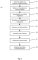
- a step 110 vehicles in the vicinity of the ego vehicle 1 are detected by means of the radar system 30 and are each provided with a unique identification ID for the purpose of object tracking.
- the ego vehicle 1 uses the radar system 30 to detect the position of the other vehicle 2, preferably in a local coordinate system moving with the ego vehicle 1, denoted by the index L (i), as a vehicle position p ID , i L i of the other vehicle 2 with the identification ID for the time i.
- a trajectory can be obtained as a description of the chronological progression of the movement of the observed other vehicle 2 in the local coordinate system moving with the ego vehicle 1 .
- the capture area for the ego lane 4 can preferably define an area that extends in the longitudinal direction up to 10 meters in front of the ego vehicle or up to 10 meters away in the longitudinal direction from the origin of a local coordinate system of the ego vehicle, and in the lateral direction up to 2 meters from the origin of the local coordinate system.
- a capture range 12, 13 can be defined for the left and/or right lane 3, 5, which extends in the longitudinal direction up to 2 meters in front of the ego vehicle 1 or up to 2 meters in the longitudinal direction from the origin of the local coordinate system of the Ego vehicle 1, as well as in the lateral direction to the left or to the right side of the ego vehicle 1 extends up to 5 meters from the origin of the local coordinate system.
- a respective vehicle position p ID , i L i determined, and the vehicle position determined within the time window p ID , i L i are propagated and converted into vehicle positions p ID , i L j in the coordinate system of the ego vehicle 1 at the current point in time j.
- trajectories obtained for the other vehicles 2a to 2e are propagated and converted into vehicle positions p ID , i L j in the coordinate system of the ego vehicle 1 at the current point in time j.
- the trajectories obtained for the other vehicles 2a to 2e can be checked for plausibility and filtered. An assessment is made as to whether the individual other vehicles 2a to 2e, whose movements are mapped by the detected trajectories, are actually other vehicles participating in traffic and moving on the lane 6 in the same direction as the ego -Vehicle 1. If this is not the case, for example because it is a trajectory of a vehicle moving in the opposite direction, or because it is a trajectory that has sudden and abrupt large changes in longitudinal and/or lateral velocity, which cannot correspond to a possible vehicle movement of a vehicle, or because it is a trajectory that is due to noise, the trajectory in question is filtered out. It can thus be prevented that the subsequent estimation of the course of the lane is falsified by other vehicles that have been incorrectly detected.
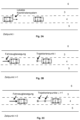
- the trajectory of the other vehicle 2a runs through the capture area 13 for the right lane 5 and accordingly, the trajectory of the other vehicle 2a is assigned to the right lane 5 .
- the trajectory of the other vehicle 2b only extends in an area at a distance in front of the ego vehicle 1, without running through one of the capture areas 11, 12, 13. Accordingly, the trajectory of the other vehicle 2b is not assigned to any lane and is therefore not further considered.
- the resulting assignment of the trajectories for the other vehicles 2a, 2c to 2e is also in the Figure 4C illustrated.
- a trajectory is assigned to a lane 3, 4, 5 based on whether the trajectory runs through a corresponding capture area 11, 12, 13 for the corresponding lane 3, 4, 5.
- this is not restrictive, and it can also be provided to assign a trajectory to a lane 3, 4, 5 if the trajectory coincides with another trajectory for at least a specified route length that has already been assigned to a lane 3, 4, 5 is.
- the trajectories already assigned on the basis of the capture areas 11, 12, 13 can be “extended” as it were, in order to allow a greater forecast.
- a step 160 at least one lane 3, 4, 5 is first selected from among the plurality of lanes 3, 4, 5, to which at least one trajectory is assigned.
- the procedure can be such that it is first checked whether the lane 4 of the ego vehicle 1 is assigned at least one trajectory. If this is the case, lane 4 of ego vehicle 1 is selected. If not, will continue checks whether at least one trajectory is assigned to a lane 3, 5 to the left or right of the ego vehicle 1, and if this is the case, the relevant lane 3, 5 or at least one of the relevant lanes 3, 5 is selected. In this way, at least one lane 3, 4, 5 can be selected in order to serve as a basis for estimating the course of lane 4 for ego vehicle 1.
- An estimate of the course of the lane is now determined for the selected lane 3, 4, 5 by performing a compensation calculation in order, for example, to determine parameters of a curve using the least squares method, which runs as optimally as possible through the set of trajectory points of the trajectories that assigned to the relevant lane 3, 4, 5.
- a polynomial of the second or higher degree, in particular a parabola, or a clothoid can be used as the curve.
- the curve determined in this way represents an estimate for the lane course of the selected lane 3, 4, 5. If the selected lane 3, 4, 5 is the lane 4 of the ego vehicle 1, the estimate obtained represents an estimate for the course of lane 4 of ego vehicle 1.
- the lateral displacement amount can first be determined, as described above, in order to shift the first curve to the origin of the local coordinate system of ego vehicle 1 .
- a sufficient number of support points is determined along the first curve, which are also spaced apart from the first curve by the amount of lateral displacement.
- the parameters of the second curve are determined, for example also with a fitting calculation, in such a way that the second curve runs as optimally as possible through the support points.
- the second curve obtained in this way now represents an estimate for the course of lane 4 for ego vehicle 1.
- FIG. 5 shows a roadway 6 with a curved course of the roadway, with no roadway markings being present in a region of the roadway 6 .
- the camera system 10 and the system 20 for camera-based lane course detection could not detect a lane 3, 4, 5 and accordingly could not determine and output a lane course.
- FIG. 5 another vehicle 2 is also shown, which is moving in the right-hand lane 5 .
- the radar sensor system 30 detects the trajectory of the other vehicle 2 and assigns it to the lane 5 to the right of the ego vehicle 1 on the basis of the course through the right-hand capture area 13 . Based on the trajectory assigned in this way, an estimate of the course of the lane for the right-hand lane 5 is now created, with this estimate in the figure 5 is illustrated as a solid line.
- a second curve is determined as described above and thus an estimate of the course of the lane for the lane 4 of the ego vehicle 1 is obtained in which figure 5 illustrated as a dotted line.
- the estimate of the respective course of the relevant lanes 3, 4, 5, as described above, can be derived and estimated based on the course of at least one neighboring lane 3, 4 or 5th up In this way, an estimate of the course of the lane can be determined for a majority or for all of lanes 3, 4 and 5.
- the present invention is not limited to the determination and output of this information, and various quality measures can also be determined and output, which allow an assessment of the quality of the estimate of the respective lane course.
- the quality measures can be particularly useful for possible driver assistance functions or other functions that work based on the estimation of the course of the lane, in order to carry out an assessment of the plausibility, reliability, range of the estimation or the like and to adjust the function execution accordingly.
- the number of other vehicles 2 whose trajectories were used as a basis for estimating the course of the lane can be determined and output as a quality measure.
- the number of trajectories that were taken into account for a respective lane 3, 4, 5 and combined in the course of determining the curve determined by the adjustment calculation provides information about how reliable the estimate of the relevant lane course is.
- an estimate of a lane course may be more trusted when the estimate was determined based on the trajectories of multiple other vehicles 2 than when the estimate was determined based on just one trajectory of another vehicle 2 .
- the distance also referred to as anticipation
- the look-ahead can be determined, for example, as the distance of the furthest away trajectory point of another vehicle 2 among all other vehicles 2 whose trajectories were used as a basis for estimating the course of the lane.
- Foresight can serve as a measure of a distance beyond which the estimation of the course of the lane is not evaluated as valid or only to a limited extent, or is evaluated with a validity that decreases with increasing distance.
- the residual error indicates how well the set of vehicle coordinates on the trajectories of a lane fit the calculated curve for the lane.
- the residual error will be small if the trajectories of a lane are very consistent with one another, i.e. if all vehicles driving in the lane have driven very similarly. On the other hand, the residual error will be the higher, the more the trajectories deviate from one another, although they were assigned to one and the same lane.
- the speed of the ego vehicle 1 and/or other criteria can be specified variably.
- the length of the time window for detecting and accumulating the trajectories and/or the temporal density of the scanning of other vehicles 2 can be selected depending on the speed of the ego vehicle 1 and/or set differently depending on the type of roadway 6 .
- a longer time window can be selected in order to allow a longer forecast.
- the time window can also be lengthened when ego vehicle 1 is moving at high speed and shortened when ego vehicle 1 is moving at lower speed, in order in this way to match the speed of the ego vehicle 1 to enable customized foresight.
- the temporal density of the scanning of vehicles 2 provision can be made, for example, to select a higher temporal density of the scanning and consequently a higher scanning frequency on an inner-city street and/or at a lower speed of the ego vehicle 1, and on a freeway and/or or at a higher speed of the ego vehicle 1 to choose a lower temporal density of the sampling, and consequently a lower sampling frequency
- the extensions of the capture areas 11, 12, 13 in the longitudinal and/or transverse direction can be enlarged or reduced depending on the type of roadway 6, a traffic situation and/or the speed of the ego vehicle 1. For example, in the case of a construction site on a freeway with correspondingly narrow lanes, the widths of the capture areas 11, 12, 13 can be adjusted accordingly.
- both the left and the right capture area 12, 13 can be activated.
- the ego vehicle 1 is moving in a lane 3, 5 of a lane 6, which represents a lane with no further lane to the right or left, the corresponding right 13 or left 12 capture area can be deactivated. It is also possible, when the ego vehicle 1 is moving on a single-lane roadway 6, to deactivate both the right-hand and the left-hand capture area 13, 12.
- the filter criteria and/or filter parameters for filtering out undesired trajectories can also be changed depending on the speed of the ego vehicle 1 and/or the type of roadway 6 .
- trajectories that describe a movement at a speed that is more than a predetermined fixed or variable threshold above the speed limit for example, exceed the speed limit by more than 30 km/h as not plausible and therefore filtered out.
- the assignment of trajectories to lanes 3, 4, 5, as described above, also allows the determination of other variables that can be relevant or useful for executing driver assistance functions. For example, average driving speeds per lane 3, 4, 5 can be determined and output for each lane 3, 4, 5 based on the assigned trajectories.
Landscapes
- Engineering & Computer Science (AREA)
- Automation & Control Theory (AREA)
- Transportation (AREA)
- Mechanical Engineering (AREA)
- Physics & Mathematics (AREA)
- Mathematical Physics (AREA)
- Traffic Control Systems (AREA)
Claims (14)
- Procédé (100) pour estimer le tracé d'une voie de circulation pour un véhicule, sous la forme d'un véhicule autonome et connecté, qui se déplace sur une chaussée (6) comprenant plusieurs voies de circulation (3, 4, 5), les étapes suivantes étant exécutées de manière répétitive :reconnaissance (110) d'un ou plusieurs autres véhicules (2) qui se déplacent sur la chaussée (6) dans la même direction que le véhicule autonome et connecté (1) ;détection (110) de positions de véhicule pour chacun des autres véhicules (2) reconnus ;formation (120) d'une trajectoire pour chacun des autres véhicules (2) reconnus en se basant sur les positions de véhicule respectivement détectées ;association (140) des trajectoires à des voies de circulation (3, 4, 5) possibles en se basant sur un tracé des trajectoires dans l'environnement du véhicule autonome et connecté (1) ;sélection (160) de l'une des voies de circulation (3, 4, 5) possibles qui est associée à au moins une trajectoire ; etestimation (170) du tracé de la voie de circulation en se basant sur l'au moins une trajectoire qui est associée à la voie de circulation (3, 4, 5) sélectionnée, caractérisé en ce quelorsqu'il est reconnu qu'une trajectoire d'un autre véhicule (2) auquel est associé une voie de circulation (3, 4, 5) croise avec son tracé au moins une trajectoire d'un autre véhicule (2) supplémentaire auquel est associée une autre voie de circulation (3, 4, 5), la trajectoire est marquée comme un changement de voie.
- Procédé (100) selon la revendication 1, en vue de l'association (140) des trajectoires à des voies de circulation (3, 4, 5) possibles en se basant sur le tracé des trajectoires dans l'environnement du véhicule autonome et connecté (1), une zone de capture (11) étant définie pour la voie de circulation (4) possible du véhicule autonome et connecté (1), et
une trajectoire étant associée à la voie de circulation (4) possible du véhicule autonome et connecté (1) lorsque la trajectoire présente au moins un point de trajectoire qui se trouve dans la zone de capture (11) pour la voie de circulation (4) possible du véhicule autonome et connecté (1). - Procédé (100) selon la revendication 2, une zone de capture (13) étant en plus définie pour une voie de circulation (5) possible à droite du véhicule autonome et connecté (1) et/ou une zone de capture (12) étant définie pour une voie de circulation (3) possible à gauche du véhicule autonome et connecté (1), et
une trajectoire étant associée à la voie de circulation possible à gauche (3) ou à droite (5) du véhicule autonome et connecté (1) lorsque la trajectoire présente au moins un point de trajectoire qui se trouve dans la zone de capture (13, 12) pour la voie de circulation gauche (3) ou droite (5) possible du véhicule autonome et connecté (1) . - Procédé (100) selon l'une des revendications précédentes, un contrôle étant effectué lors de la sélection (160) d'une voie de circulation (3, 4, 5) qui est associée à au moins une trajectoire afin de vérifier si au moins une trajectoire est associée à la voie de circulation (4) du véhicule autonome et connecté (1) et, dans l'affirmative, la voie de circulation (4) du véhicule autonome et connecté (1) est sélectionnée.
- Procédé (100) selon la revendication 4, un contrôle étant effectué lorsqu'aucune trajectoire n'est associée à la voie de circulation (4) du véhicule autonome et connecté (1) afin de vérifier si au moins une trajectoire est associée à une voie de circulation (3, 5) à gauche ou à droite du véhicule autonome et connecté (1) et, dans l'affirmative, la voie de circulation (3, 5) concernée est sélectionnée.
- Procédé (100) selon l'une des revendications précédentes, un calcul de compensation étant effectué pour l'estimation (170) du tracé de la voie de circulation afin de déterminer des paramètres d'un polynôme du deuxième degré ou plus, ou d'une clothoïde, qui est défini(e) par l'ensemble des points de trajectoire de l'au moins une trajectoire, le calcul de compensation se basant de préférence sur la méthode des moindres carrés.
- Procédé (100) selon l'une des revendications précédentes, comprenant en outre le calcul et la délivrance d'au moins un indice de qualité, l'au moins un indice de qualité comprenant :le nombre d'autres véhicules (2) considérés sur la voie de circulation (3, 4, 5) sélectionnée ou sur chacune des voies de circulation (3, 4, 5) ;la prévision pour la voie de circulation (3, 4, 5) sélectionnée ou pour chacune des voies de circulation (3, 4, 5) ; et/oul'erreur résiduelle se produisant lors de l'exécution du calcul de compensation.
- Procédé (100) selon l'une des revendications précédentes, comprenant en outre une étape de vérification de la plausibilité et/ou de filtrage (130) des trajectoires.
- Procédé d'assistance au conducteur destiné à assister un conducteur lors de la conduite d'un véhicule, sous la forme d'un véhicule autonome et connecté (1), comprenant les étapes suivantes :estimation d'un tracé de la voie de circulation (4) du véhicule autonome et connecté (1) en mettant en œuvre le procédé (100) selon l'une des revendications 1 à 8 ;reconnaissance du tracé de la voie de circulation (4) du véhicule autonome et connecté (1) au moyen d'un système de reconnaissance de voie de circulation à base de caméra et/ou à base de LIDAR ; etexécution d'au moins une fonction d'assistance au conducteur en se basant sur le tracé estimé de la voie de circulation et le tracé reconnu de la voie de circulation, la plausibilité des informations à propos du tracé reconnu de la voie de circulation étant vérifiée au moyen des informations à propos du tracé estimé de la voie de circulation, la fonction d'assistance au conducteur, lorsque les informations à propos du tracé reconnu de la voie de circulation sont évaluées non plausibles, étant exécutée uniquement sur la base des informations à propos du tracé estimé de la voie de circulation, et/oula plausibilité des informations à propos du tracé estimé de la voie de circulation étant vérifiée au moyen des informations à propos du tracé reconnu de la voie de circulation, la fonction d'assistance au conducteur, lorsque les informations à propos du tracé estimé de la voie de circulation sont évaluées non plausibles, étant exécutée uniquement sur la base des informations à propos du tracé reconnu de la voie de circulation.
- Procédé d'assistance au conducteur selon la revendication 9, comprenant en outre la fusion des informations à propos du tracé estimé de la voie de circulation et des informations à propos du tracé reconnu de la voie de circulation afin d'obtenir des informations d'un tracé de voie de circulation fusionné, la fonction d'assistance au conducteur étant exécutée sur la base des informations à propos du tracé de voie de circulation fusionné.
- Système (50) pour estimer le tracé d'une voie de circulation pour un véhicule, sous la forme d'un véhicule autonome et connecté (1), lors d'un déplacement sur une chaussée (6) comprenant plusieurs voies de circulation (3, 4, 5), comprenant :des moyens de reconnaissance d'objet, qui sont conçus pour reconnaître un ou plusieurs autres véhicules (2) qui se déplacent sur la chaussée (6) dans la même direction que le véhicule autonome et connecté (1) ;de moyens de détection de position de véhicule, qui sont conçus pour détecter les positions de véhicule pour chacun des autres véhicules (2) reconnus ;des moyens de formation de trajectoire, qui sont conçus pour former une trajectoire pour chacun des autres véhicules (2) reconnus ;des moyens d'association de trajectoire, qui sont conçus pour associer les trajectoires formées à des voies de circulation (3, 4, 5) possibles en se basant sur un tracé des trajectoires dans l'environnement du véhicule autonome et connecté (1) ;des moyens de sélection, qui sont conçus pour sélectionner, parmi la pluralité de voies de circulation (3, 4, 5) possibles, une voie de circulation (3, 4, 5) qui est associée à au moins une trajectoire ; etdes moyens d'estimation de tracé de voie de circulation, qui sont conçus pour estimer le tracé de la voie de circulation en se basant sur l'au moins une trajectoire qui est associée à la voie de circulation (3, 4, 5) sélectionnée,caractérisé en ce quele système (50) est conçu pour, lorsqu'il reconnaît qu'une trajectoire d'un autre véhicule (2) auquel est associé une voie de circulation (3, 4, 5) croise avec son tracé au moins une trajectoire d'un autre véhicule (2) supplémentaire auquel est associée une autre voie de circulation (3, 4, 5), marquer la trajectoire comme un changement de voie.
- Système (50) selon la revendication 11,en vue de l'association (140) des trajectoires à des voies de circulation (3, 4, 5) possibles en se basant sur le tracé des trajectoires dans l'environnement du véhicule autonome et connecté (1), une zone de capture (11) étant définie pour la voie de circulation (4) possible du véhicule autonome et connecté (1), et de préférence en plus une zone de capture (13) étant définie pour une voie de circulation (5) possible à droite du véhicule autonome et connecté (1) et/ou une zone de capture (12) étant définie pour une voie de circulation (3) possible à gauche du véhicule autonome et connecté (1) ;les moyens d'association de trajectoire étant conçus pour associer une trajectoire à la voie de circulation (4) possible du véhicule autonome et connecté (1) lorsque la trajectoire présente au moins un point de trajectoire qui se trouve dans la zone de capture (11) pour la voie de circulation (4) possible du véhicule autonome et connecté (1), et étant de préférence en plus conçus pour associer une trajectoire à la voie de circulation possible à gauche (3) ou à droite (5) du véhicule autonome et connecté (1) lorsque la trajectoire présente au moins un point de trajectoire qui se trouve dans la zone de capture (13, 12) pour la voie de circulation gauche (3) ou droite (5) possible du véhicule autonome et connecté (1) ; et les moyens d'association de trajectoire étant conçus pour, en vue de sélectionner (160) une voie de circulation (3, 4, 5) qui est associée à moins une trajectoire, vérifier si au moins une trajectoire est associée à la voie de circulation (4) du véhicule autonome et connecté (1) et, dans l'affirmative, sélectionner la voie de circulation (4) du véhicule autonome et connecté (1), et de préférence étant en plus conçus pour, lorsqu'aucune trajectoire n'est associée à la voie de circulation (4) du véhicule autonome et connecté (1), vérifier si au moins une trajectoire est associée à une voie de circulation (3, 5) à gauche ou à droite du véhicule autonome et connecté (1) et, dans l'affirmative, sélectionner la voie de circulation (3, 5) concernée.
- Système (50) selon l'une des revendications 11 ou 12, le système (50) étant conçu pour mettre en œuvre le procédé (100) selon l'une des revendications 1 à 13.
- Véhicule (1), possédant un système (50) selon l'une des revendications 11 à 13.
Applications Claiming Priority (2)
| Application Number | Priority Date | Filing Date | Title |
|---|---|---|---|
| DE102014200638.4A DE102014200638A1 (de) | 2014-01-16 | 2014-01-16 | Verfahren und System zum Schätzen eines Fahrspurverlaufs |
| PCT/EP2014/078188 WO2015106913A1 (fr) | 2014-01-16 | 2014-12-17 | Procédé et système pour évaluer le tracé d'une voie de circulation |
Publications (2)
| Publication Number | Publication Date |
|---|---|
| EP3094530A1 EP3094530A1 (fr) | 2016-11-23 |
| EP3094530B1 true EP3094530B1 (fr) | 2023-05-31 |
Family
ID=52292895
Family Applications (1)
| Application Number | Title | Priority Date | Filing Date |
|---|---|---|---|
| EP14824434.6A Active EP3094530B1 (fr) | 2014-01-16 | 2014-12-17 | Procédé et système pour évaluer le tracé d'une voie de circulation |
Country Status (3)
| Country | Link |
|---|---|
| EP (1) | EP3094530B1 (fr) |
| DE (1) | DE102014200638A1 (fr) |
| WO (1) | WO2015106913A1 (fr) |
Families Citing this family (27)
| Publication number | Priority date | Publication date | Assignee | Title |
|---|---|---|---|---|
| JP6055525B1 (ja) | 2015-09-02 | 2016-12-27 | 富士重工業株式会社 | 車両の走行制御装置 |
| DE102016201667B4 (de) * | 2016-02-03 | 2019-06-19 | Volkswagen Aktiengesellschaft | Verfahren zum Bestimmen einer Solltrajektorie für einen ersten Verkehrsteilnehmer, insbesondere für ein Kraftfahrzeug, für einen Streckenabschnitt |
| DE102016205442B4 (de) * | 2016-04-01 | 2025-06-18 | Bayerische Motoren Werke Aktiengesellschaft | Verfahren zur Optimierung einer Pfadplanung eines Fahrzeugs |
| DE102016007567A1 (de) | 2016-06-21 | 2017-12-21 | Audi Ag | Verfahren zum Betreiben eines zum Ermitteln einer zu befahrenden Trajektorie und/oder zum Durchführen von Fahreingriffen ausgebildeten Fahrzeugsystems, Verfahren zum Betreiben eines Steuerungssystems und Kraftfahrzeug |
| DE102016118497A1 (de) | 2016-09-29 | 2018-03-29 | Valeo Schalter Und Sensoren Gmbh | Ermittlung einer virtuellen Fahrspur für eine von einem Kraftfahrzeug befahrene Straße |
| EP3360747A1 (fr) | 2017-02-13 | 2018-08-15 | Autoliv Development AB | Perfectionnements apportés ou se rapportant à des systèmes d'assistance au conducteur |
| US10267911B2 (en) | 2017-03-31 | 2019-04-23 | Ford Global Technologies, Llc | Steering wheel actuation |
| DE102017206847B4 (de) | 2017-04-24 | 2020-08-13 | Robert Bosch Gmbh | Verfahren zum automatischen Erstellen und Aktualisieren eines Datensatzes für ein autonomes Fahrzeug |
| DE102017216237A1 (de) * | 2017-09-14 | 2019-03-14 | Bayerische Motoren Werke Aktiengesellschaft | Verfahren zum Ermitteln eines Verlaufs von Fahrspuren eines Straßennetzes sowie Servervorrichtung zum Durchführen des Verfahrens |
| DE102017009435B4 (de) * | 2017-10-10 | 2023-05-11 | Volkswagen Ag | Evaluation von Komponenten automatischer Fahrfunktionen und Fahrbahnerkennung auf unterschiedlichen Verarbeitungsstufen |
| DE102018202970A1 (de) * | 2018-02-28 | 2019-08-29 | Robert Bosch Gmbh | Verfahren zum Ermitteln einer topologischen Information einer Straßenkreuzung |
| DE102018213401A1 (de) * | 2018-08-09 | 2020-02-13 | Conti Temic Microelectronic Gmbh | Verfahren zur dynamischen Anpassung eines Schwellwerts für die Auslösung einer Fahrerassistenzfunktion |
| US11022457B2 (en) | 2018-10-23 | 2021-06-01 | Here Global B.V. | Method, apparatus, and computer program product for lane-level route guidance |
| US10982969B2 (en) | 2018-10-23 | 2021-04-20 | Here Global B.V. | Method, apparatus, and computer program product for lane-level route guidance |
| FR3088280A1 (fr) * | 2018-11-08 | 2020-05-15 | Psa Automobiles Sa | Construction par segmentation de voies virtuelles sur une chaussee |
| DE102018127864A1 (de) * | 2018-11-08 | 2020-05-14 | Valeo Schalter Und Sensoren Gmbh | Verfahren zum Bestimmen der Fahrspur eines Fahrzeugs |
| DE102019102922A1 (de) * | 2019-02-06 | 2020-08-06 | Bayerische Motoren Werke Aktiengesellschaft | Verfahren und Vorrichtung zur Multi-Sensor-Datenfusion für automatisierte und autonome Fahrzeuge |
| US11117577B2 (en) | 2019-02-22 | 2021-09-14 | Ford Global Technologies, Llc | Vehicle path processing |
| CN112612277B (zh) * | 2020-12-23 | 2023-03-07 | 禾多科技(北京)有限公司 | 车辆轨迹规划方法、装置、设备和计算机可读介质 |
| DE102021003069A1 (de) | 2021-06-15 | 2022-12-15 | Mercedes-Benz Group AG | Verfahren zum Betrieb eines Fahrzeuges in einem automatisierten Fahrbetrieb |
| CN113990064B (zh) * | 2021-09-14 | 2023-02-17 | 北京无限感测科技有限公司 | 一种交通数据采集方法、系统和计算机可读存储介质 |
| DE102021210924B4 (de) | 2021-09-29 | 2026-05-07 | Volkswagen Aktiengesellschaft | Verfahren zum Querführen eines Kraftfahrzeugs auf einer Straße mit wenigstens zwei Fahrspuren sowie Kraftfahrzeug |
| GB2618616A (en) * | 2022-05-13 | 2023-11-15 | Aptiv Tech Ltd | Vehicle lane determination method, computer program product, and apparatus |
| CN114802233B (zh) * | 2022-06-22 | 2022-09-16 | 小米汽车科技有限公司 | 车辆控制方法、装置、电子设备及存储介质 |
| DE102023207971A1 (de) * | 2023-08-21 | 2025-02-27 | Volkswagen Aktiengesellschaft | Verfahren zum Ermitteln einer erwarteten Fahrtrajektorie eines Kraftfahrzeugs |
| DE102024111898A1 (de) * | 2024-04-29 | 2025-10-30 | Audi Aktiengesellschaft | Verfahren zum Betreiben eines Steuergeräts für ein Kraftfahrzeug, entsprechendes Steuergerät für ein Kraftfahrzeug sowie Computerprogrammprodukt |
| DE102024003116A1 (de) | 2024-09-26 | 2024-11-21 | Mercedes-Benz Group AG | Verfahren zum Betreiben eines zumindest teilweise assistiert betriebenen Kraftfahrzeugs mittels eines Assistenzsystems, sowie Assistenzsystem |
Citations (3)
| Publication number | Priority date | Publication date | Assignee | Title |
|---|---|---|---|---|
| DE102005029662A1 (de) * | 2004-06-22 | 2006-01-19 | Deutsches Zentrum für Luft- und Raumfahrt e.V. | Umgebungserfassung bei Landfahrzeugen |
| DE102005039103A1 (de) * | 2005-08-18 | 2007-03-01 | Robert Bosch Gmbh | Verfahren für die Erfassung eines Verkehrsraums |
| DE102006037993A1 (de) * | 2005-08-18 | 2007-04-26 | GM Global Technology Operations, Inc., Detroit | System und Verfahren zum Detektieren einer Kollision und Vorhersagen eines Fahrzeugpfads |
Family Cites Families (10)
| Publication number | Priority date | Publication date | Assignee | Title |
|---|---|---|---|---|
| DE19855400A1 (de) * | 1998-12-01 | 2000-06-15 | Bosch Gmbh Robert | Verfahren und Vorrichtung zur Bestimmung eines zukünftigen Kursbereichs eines Fahrzeugs |
| EP1074430B1 (fr) | 1999-08-04 | 2007-10-17 | Iteris, Inc. | Sytème et méthode d'imagerie avec commande dynamique de luminosité |
| EP1315980B1 (fr) | 2000-09-08 | 2006-10-04 | Raytheon Company | Systeme et procede de prevision de trajectoire |
| DE10349631A1 (de) | 2003-10-24 | 2005-05-19 | Robert Bosch Gmbh | Fahrerassistenzverfahren und -vorrichtung auf der Basis von Fahrspurinformationen |
| DE102004008868A1 (de) | 2004-02-20 | 2005-09-08 | Daimlerchrysler Ag | Verfahren zur Spurerkennung einer Fahrspur für ein Kraftfahrzeug |
| DE102004028404A1 (de) | 2004-06-14 | 2006-01-19 | Daimlerchrysler Ag | Verfahren zur Schätzung des Verlaufs einer Fahrspur eines Kraftfahrzeuges |
| DE102005002504A1 (de) | 2005-01-19 | 2006-07-27 | Robert Bosch Gmbh | Fahrerassistenzsystem mit Fahrschlauchprädiktion |
| DE102006009656A1 (de) | 2006-03-02 | 2007-09-06 | Robert Bosch Gmbh | Fahrerassistenzsystem mit Kursprädiktionsmodul |
| JP4793094B2 (ja) * | 2006-05-17 | 2011-10-12 | 株式会社デンソー | 走行環境認識装置 |
| DE102010020984A1 (de) * | 2010-04-20 | 2011-10-20 | Conti Temic Microelectronic Gmbh | Verfahren zur Bestimmung des Fahrbahnverlaufes für ein Kraftfahrzeug |
-
2014
- 2014-01-16 DE DE102014200638.4A patent/DE102014200638A1/de not_active Withdrawn
- 2014-12-17 WO PCT/EP2014/078188 patent/WO2015106913A1/fr not_active Ceased
- 2014-12-17 EP EP14824434.6A patent/EP3094530B1/fr active Active
Patent Citations (3)
| Publication number | Priority date | Publication date | Assignee | Title |
|---|---|---|---|---|
| DE102005029662A1 (de) * | 2004-06-22 | 2006-01-19 | Deutsches Zentrum für Luft- und Raumfahrt e.V. | Umgebungserfassung bei Landfahrzeugen |
| DE102005039103A1 (de) * | 2005-08-18 | 2007-03-01 | Robert Bosch Gmbh | Verfahren für die Erfassung eines Verkehrsraums |
| DE102006037993A1 (de) * | 2005-08-18 | 2007-04-26 | GM Global Technology Operations, Inc., Detroit | System und Verfahren zum Detektieren einer Kollision und Vorhersagen eines Fahrzeugpfads |
Also Published As
| Publication number | Publication date |
|---|---|
| EP3094530A1 (fr) | 2016-11-23 |
| WO2015106913A1 (fr) | 2015-07-23 |
| DE102014200638A1 (de) | 2015-07-30 |
Similar Documents
| Publication | Publication Date | Title |
|---|---|---|
| EP3094530A1 (fr) | Procédé et système pour évaluer le tracé d'une voie de circulation | |
| EP1684142B1 (fr) | Procédé pour la prédiction du course future et du contrôle de la distance inter-véhicule dans un système d'assistance | |
| EP3160813B1 (fr) | Procédé de création d'un modèle d'environnement d'un véhicule | |
| DE102013113163B4 (de) | Fahrzeugfahrtunterstützungssteuerungsvorrichtung | |
| EP1680317B1 (fr) | Procede d'assistance au conducteur et dispositif fonctionnant sur la base d'informations de voies de circulation | |
| DE112010003874B4 (de) | Fahrzeugsteuerung | |
| DE102010050167B4 (de) | Verfahren und Vorrichtung zur Bestimmung eines plausiblen Fahrstreifens zur Führung eines Fahrzeugs sowie Kraftwagen | |
| DE102011117554B4 (de) | Fahrumgebungserfassungsvorrichtung | |
| DE102017203654B4 (de) | Verfahren zum Betreiben eines Fahrerassistenzsystems für ein Fahrzeug auf einer Straße und Fahrerassistenzsystem | |
| DE112016000422B4 (de) | Geschwindigkeitsregelvorrichtung und geschwindigkeitsregelverfahren für fahrzeuge | |
| DE112017003974B4 (de) | Geschwindigkeitsregelungsvorrichtung | |
| DE102018218220A1 (de) | Steuergerät für ein Fahrzeug | |
| EP2594461B1 (fr) | Procédé de détection d'une place de stationnement pour un véhicule automobile, système d'aide au stationnement et véhicule automobile équipé d'un système d'aide au stationnement | |
| DE102017212607A1 (de) | Verfahren und Vorrichtung zur umgebungsbasierten Adaption von Fahrerassistenzsystem-Funktionen | |
| DE102014200700A1 (de) | Verfahren und System zur Erkennung einer Rettungsgassensituation | |
| EP4158611B1 (fr) | Assistant de voie d'urgence | |
| EP0915350A2 (fr) | Dispositif pour déterminer des données indicatives de l'évolution des voies de circulation | |
| EP2676857A2 (fr) | Procédé et dispositif de génération d'un paramètre de commande pour un système d'assistance de distance d'un véhicule | |
| DE102013201796B4 (de) | Verfahren zur Bereitstellung eines Fahrkorridors für ein Fahrzeug und Fahrassistenzsystem | |
| DE102005003192A1 (de) | Verfahren zur Kursprädiktion in Fahrerassistenzsystemen für Kraftfahrzeuge | |
| DE102012208302C5 (de) | Verfahren zur Bereitstellung von Informationen über eine Umgebung eines Fahrzeugs | |
| DE102017205245B4 (de) | Freibereichsfusion für Fahrerassistenzsysteme | |
| DE102017106349A1 (de) | Fahrerassistenzsystem für ein Fahrzeug zum Prognostizieren eines dem Fahrzeug vorausliegenden Fahrspurbereichs, Fahrzeug und Verfahren | |
| DE10359241A1 (de) | Fahrunterstützungssystem, Fahrunterstützungsvorrichtung und Fahrunterstützungsverfahren für ein Fahrzeug | |
| DE102016201190A1 (de) | Wendeassistent |
Legal Events
| Date | Code | Title | Description |
|---|---|---|---|
| PUAI | Public reference made under article 153(3) epc to a published international application that has entered the european phase |
Free format text: ORIGINAL CODE: 0009012 |
|
| 17P | Request for examination filed |
Effective date: 20160721 |
|
| AK | Designated contracting states |
Kind code of ref document: A1 Designated state(s): AL AT BE BG CH CY CZ DE DK EE ES FI FR GB GR HR HU IE IS IT LI LT LU LV MC MK MT NL NO PL PT RO RS SE SI SK SM TR |
|
| AX | Request for extension of the european patent |
Extension state: BA ME |
|
| DAX | Request for extension of the european patent (deleted) | ||
| STAA | Information on the status of an ep patent application or granted ep patent |
Free format text: STATUS: EXAMINATION IS IN PROGRESS |
|
| 17Q | First examination report despatched |
Effective date: 20210319 |
|
| GRAP | Despatch of communication of intention to grant a patent |
Free format text: ORIGINAL CODE: EPIDOSNIGR1 |
|
| STAA | Information on the status of an ep patent application or granted ep patent |
Free format text: STATUS: GRANT OF PATENT IS INTENDED |
|
| INTG | Intention to grant announced |
Effective date: 20230130 |
|
| GRAS | Grant fee paid |
Free format text: ORIGINAL CODE: EPIDOSNIGR3 |
|
| GRAA | (expected) grant |
Free format text: ORIGINAL CODE: 0009210 |
|
| STAA | Information on the status of an ep patent application or granted ep patent |
Free format text: STATUS: THE PATENT HAS BEEN GRANTED |
|
| AK | Designated contracting states |
Kind code of ref document: B1 Designated state(s): AL AT BE BG CH CY CZ DE DK EE ES FI FR GB GR HR HU IE IS IT LI LT LU LV MC MK MT NL NO PL PT RO RS SE SI SK SM TR |
|
| REG | Reference to a national code |
Ref country code: GB Ref legal event code: FG4D Free format text: NOT ENGLISH Ref country code: CH Ref legal event code: EP |
|
| REG | Reference to a national code |
Ref country code: DE Ref legal event code: R096 Ref document number: 502014016577 Country of ref document: DE |
|
| P01 | Opt-out of the competence of the unified patent court (upc) registered |
Effective date: 20230502 |
|
| REG | Reference to a national code |
Ref country code: AT Ref legal event code: REF Ref document number: 1570761 Country of ref document: AT Kind code of ref document: T Effective date: 20230615 |
|
| REG | Reference to a national code |
Ref country code: IE Ref legal event code: FG4D Free format text: LANGUAGE OF EP DOCUMENT: GERMAN |
|
| P02 | Opt-out of the competence of the unified patent court (upc) changed |
Effective date: 20230727 |
|
| REG | Reference to a national code |
Ref country code: LT Ref legal event code: MG9D |
|
| REG | Reference to a national code |
Ref country code: NL Ref legal event code: MP Effective date: 20230531 |
|
| PG25 | Lapsed in a contracting state [announced via postgrant information from national office to epo] |
Ref country code: SE Free format text: LAPSE BECAUSE OF FAILURE TO SUBMIT A TRANSLATION OF THE DESCRIPTION OR TO PAY THE FEE WITHIN THE PRESCRIBED TIME-LIMIT Effective date: 20230531 Ref country code: NO Free format text: LAPSE BECAUSE OF FAILURE TO SUBMIT A TRANSLATION OF THE DESCRIPTION OR TO PAY THE FEE WITHIN THE PRESCRIBED TIME-LIMIT Effective date: 20230831 Ref country code: ES Free format text: LAPSE BECAUSE OF FAILURE TO SUBMIT A TRANSLATION OF THE DESCRIPTION OR TO PAY THE FEE WITHIN THE PRESCRIBED TIME-LIMIT Effective date: 20230531 |
|
| PG25 | Lapsed in a contracting state [announced via postgrant information from national office to epo] |
Ref country code: RS Free format text: LAPSE BECAUSE OF FAILURE TO SUBMIT A TRANSLATION OF THE DESCRIPTION OR TO PAY THE FEE WITHIN THE PRESCRIBED TIME-LIMIT Effective date: 20230531 Ref country code: PL Free format text: LAPSE BECAUSE OF FAILURE TO SUBMIT A TRANSLATION OF THE DESCRIPTION OR TO PAY THE FEE WITHIN THE PRESCRIBED TIME-LIMIT Effective date: 20230531 Ref country code: NL Free format text: LAPSE BECAUSE OF FAILURE TO SUBMIT A TRANSLATION OF THE DESCRIPTION OR TO PAY THE FEE WITHIN THE PRESCRIBED TIME-LIMIT Effective date: 20230531 Ref country code: LV Free format text: LAPSE BECAUSE OF FAILURE TO SUBMIT A TRANSLATION OF THE DESCRIPTION OR TO PAY THE FEE WITHIN THE PRESCRIBED TIME-LIMIT Effective date: 20230531 Ref country code: LT Free format text: LAPSE BECAUSE OF FAILURE TO SUBMIT A TRANSLATION OF THE DESCRIPTION OR TO PAY THE FEE WITHIN THE PRESCRIBED TIME-LIMIT Effective date: 20230531 Ref country code: IS Free format text: LAPSE BECAUSE OF FAILURE TO SUBMIT A TRANSLATION OF THE DESCRIPTION OR TO PAY THE FEE WITHIN THE PRESCRIBED TIME-LIMIT Effective date: 20230930 Ref country code: HR Free format text: LAPSE BECAUSE OF FAILURE TO SUBMIT A TRANSLATION OF THE DESCRIPTION OR TO PAY THE FEE WITHIN THE PRESCRIBED TIME-LIMIT Effective date: 20230531 Ref country code: GR Free format text: LAPSE BECAUSE OF FAILURE TO SUBMIT A TRANSLATION OF THE DESCRIPTION OR TO PAY THE FEE WITHIN THE PRESCRIBED TIME-LIMIT Effective date: 20230901 |
|
| PG25 | Lapsed in a contracting state [announced via postgrant information from national office to epo] |
Ref country code: FI Free format text: LAPSE BECAUSE OF FAILURE TO SUBMIT A TRANSLATION OF THE DESCRIPTION OR TO PAY THE FEE WITHIN THE PRESCRIBED TIME-LIMIT Effective date: 20230531 |
|
| PG25 | Lapsed in a contracting state [announced via postgrant information from national office to epo] |
Ref country code: SK Free format text: LAPSE BECAUSE OF FAILURE TO SUBMIT A TRANSLATION OF THE DESCRIPTION OR TO PAY THE FEE WITHIN THE PRESCRIBED TIME-LIMIT Effective date: 20230531 |
|
| PG25 | Lapsed in a contracting state [announced via postgrant information from national office to epo] |
Ref country code: SM Free format text: LAPSE BECAUSE OF FAILURE TO SUBMIT A TRANSLATION OF THE DESCRIPTION OR TO PAY THE FEE WITHIN THE PRESCRIBED TIME-LIMIT Effective date: 20230531 Ref country code: SK Free format text: LAPSE BECAUSE OF FAILURE TO SUBMIT A TRANSLATION OF THE DESCRIPTION OR TO PAY THE FEE WITHIN THE PRESCRIBED TIME-LIMIT Effective date: 20230531 Ref country code: RO Free format text: LAPSE BECAUSE OF FAILURE TO SUBMIT A TRANSLATION OF THE DESCRIPTION OR TO PAY THE FEE WITHIN THE PRESCRIBED TIME-LIMIT Effective date: 20230531 Ref country code: PT Free format text: LAPSE BECAUSE OF FAILURE TO SUBMIT A TRANSLATION OF THE DESCRIPTION OR TO PAY THE FEE WITHIN THE PRESCRIBED TIME-LIMIT Effective date: 20231002 Ref country code: EE Free format text: LAPSE BECAUSE OF FAILURE TO SUBMIT A TRANSLATION OF THE DESCRIPTION OR TO PAY THE FEE WITHIN THE PRESCRIBED TIME-LIMIT Effective date: 20230531 Ref country code: DK Free format text: LAPSE BECAUSE OF FAILURE TO SUBMIT A TRANSLATION OF THE DESCRIPTION OR TO PAY THE FEE WITHIN THE PRESCRIBED TIME-LIMIT Effective date: 20230531 Ref country code: CZ Free format text: LAPSE BECAUSE OF FAILURE TO SUBMIT A TRANSLATION OF THE DESCRIPTION OR TO PAY THE FEE WITHIN THE PRESCRIBED TIME-LIMIT Effective date: 20230531 |
|
| REG | Reference to a national code |
Ref country code: DE Ref legal event code: R097 Ref document number: 502014016577 Country of ref document: DE |
|
| PLBE | No opposition filed within time limit |
Free format text: ORIGINAL CODE: 0009261 |
|
| STAA | Information on the status of an ep patent application or granted ep patent |
Free format text: STATUS: NO OPPOSITION FILED WITHIN TIME LIMIT |
|
| PG25 | Lapsed in a contracting state [announced via postgrant information from national office to epo] |
Ref country code: SI Free format text: LAPSE BECAUSE OF FAILURE TO SUBMIT A TRANSLATION OF THE DESCRIPTION OR TO PAY THE FEE WITHIN THE PRESCRIBED TIME-LIMIT Effective date: 20230531 |
|
| 26N | No opposition filed |
Effective date: 20240301 |
|
| PG25 | Lapsed in a contracting state [announced via postgrant information from national office to epo] |
Ref country code: SI Free format text: LAPSE BECAUSE OF FAILURE TO SUBMIT A TRANSLATION OF THE DESCRIPTION OR TO PAY THE FEE WITHIN THE PRESCRIBED TIME-LIMIT Effective date: 20230531 |
|
| REG | Reference to a national code |
Ref country code: CH Ref legal event code: PL |
|
| PG25 | Lapsed in a contracting state [announced via postgrant information from national office to epo] |
Ref country code: LU Free format text: LAPSE BECAUSE OF NON-PAYMENT OF DUE FEES Effective date: 20231217 |
|
| PG25 | Lapsed in a contracting state [announced via postgrant information from national office to epo] |
Ref country code: MC Free format text: LAPSE BECAUSE OF FAILURE TO SUBMIT A TRANSLATION OF THE DESCRIPTION OR TO PAY THE FEE WITHIN THE PRESCRIBED TIME-LIMIT Effective date: 20230531 |
|
| REG | Reference to a national code |
Ref country code: BE Ref legal event code: MM Effective date: 20231231 |
|
| PG25 | Lapsed in a contracting state [announced via postgrant information from national office to epo] |
Ref country code: MC Free format text: LAPSE BECAUSE OF FAILURE TO SUBMIT A TRANSLATION OF THE DESCRIPTION OR TO PAY THE FEE WITHIN THE PRESCRIBED TIME-LIMIT Effective date: 20230531 Ref country code: LU Free format text: LAPSE BECAUSE OF NON-PAYMENT OF DUE FEES Effective date: 20231217 |
|
| REG | Reference to a national code |
Ref country code: IE Ref legal event code: MM4A |
|
| PG25 | Lapsed in a contracting state [announced via postgrant information from national office to epo] |
Ref country code: IE Free format text: LAPSE BECAUSE OF NON-PAYMENT OF DUE FEES Effective date: 20231217 |
|
| PG25 | Lapsed in a contracting state [announced via postgrant information from national office to epo] |
Ref country code: BE Free format text: LAPSE BECAUSE OF NON-PAYMENT OF DUE FEES Effective date: 20231231 |
|
| PG25 | Lapsed in a contracting state [announced via postgrant information from national office to epo] |
Ref country code: CH Free format text: LAPSE BECAUSE OF NON-PAYMENT OF DUE FEES Effective date: 20231231 |
|
| PG25 | Lapsed in a contracting state [announced via postgrant information from national office to epo] |
Ref country code: IE Free format text: LAPSE BECAUSE OF NON-PAYMENT OF DUE FEES Effective date: 20231217 Ref country code: CH Free format text: LAPSE BECAUSE OF NON-PAYMENT OF DUE FEES Effective date: 20231231 Ref country code: BE Free format text: LAPSE BECAUSE OF NON-PAYMENT OF DUE FEES Effective date: 20231231 |
|
| PG25 | Lapsed in a contracting state [announced via postgrant information from national office to epo] |
Ref country code: BG Free format text: LAPSE BECAUSE OF FAILURE TO SUBMIT A TRANSLATION OF THE DESCRIPTION OR TO PAY THE FEE WITHIN THE PRESCRIBED TIME-LIMIT Effective date: 20230531 |
|
| PG25 | Lapsed in a contracting state [announced via postgrant information from national office to epo] |
Ref country code: BG Free format text: LAPSE BECAUSE OF FAILURE TO SUBMIT A TRANSLATION OF THE DESCRIPTION OR TO PAY THE FEE WITHIN THE PRESCRIBED TIME-LIMIT Effective date: 20230531 |
|
| REG | Reference to a national code |
Ref country code: AT Ref legal event code: MM01 Ref document number: 1570761 Country of ref document: AT Kind code of ref document: T Effective date: 20231217 |
|
| PG25 | Lapsed in a contracting state [announced via postgrant information from national office to epo] |
Ref country code: AT Free format text: LAPSE BECAUSE OF NON-PAYMENT OF DUE FEES Effective date: 20231217 |
|
| PG25 | Lapsed in a contracting state [announced via postgrant information from national office to epo] |
Ref country code: CY Free format text: LAPSE BECAUSE OF FAILURE TO SUBMIT A TRANSLATION OF THE DESCRIPTION OR TO PAY THE FEE WITHIN THE PRESCRIBED TIME-LIMIT; INVALID AB INITIO Effective date: 20141217 |
|
| PG25 | Lapsed in a contracting state [announced via postgrant information from national office to epo] |
Ref country code: HU Free format text: LAPSE BECAUSE OF FAILURE TO SUBMIT A TRANSLATION OF THE DESCRIPTION OR TO PAY THE FEE WITHIN THE PRESCRIBED TIME-LIMIT; INVALID AB INITIO Effective date: 20141217 |
|
| PG25 | Lapsed in a contracting state [announced via postgrant information from national office to epo] |
Ref country code: TR Free format text: LAPSE BECAUSE OF FAILURE TO SUBMIT A TRANSLATION OF THE DESCRIPTION OR TO PAY THE FEE WITHIN THE PRESCRIBED TIME-LIMIT Effective date: 20230531 |
|
| PGFP | Annual fee paid to national office [announced via postgrant information from national office to epo] |
Ref country code: DE Payment date: 20251203 Year of fee payment: 12 |
|
| PGFP | Annual fee paid to national office [announced via postgrant information from national office to epo] |
Ref country code: GB Payment date: 20251218 Year of fee payment: 12 |
|
| PGFP | Annual fee paid to national office [announced via postgrant information from national office to epo] |
Ref country code: FR Payment date: 20251218 Year of fee payment: 12 |
|
| PGFP | Annual fee paid to national office [announced via postgrant information from national office to epo] |
Ref country code: IT Payment date: 20251231 Year of fee payment: 12 |