EP3094571B1 - Abgabeverschlussanordnung mit vorabentlüftung - Google Patents
Abgabeverschlussanordnung mit vorabentlüftung Download PDFInfo
- Publication number
- EP3094571B1 EP3094571B1 EP15737938.9A EP15737938A EP3094571B1 EP 3094571 B1 EP3094571 B1 EP 3094571B1 EP 15737938 A EP15737938 A EP 15737938A EP 3094571 B1 EP3094571 B1 EP 3094571B1
- Authority
- EP
- European Patent Office
- Prior art keywords
- sealing
- dispensing
- closure
- collar
- tip
- Prior art date
- Legal status (The legal status is an assumption and is not a legal conclusion. Google has not performed a legal analysis and makes no representation as to the accuracy of the status listed.)
- Active
Links
- 230000003405 preventing effect Effects 0.000 title description 9
- 238000007789 sealing Methods 0.000 claims description 175
- 238000013022 venting Methods 0.000 claims description 20
- 230000004323 axial length Effects 0.000 claims description 8
- 238000004891 communication Methods 0.000 claims description 4
- 239000007788 liquid Substances 0.000 description 19
- 239000007789 gas Substances 0.000 description 9
- IJGRMHOSHXDMSA-UHFFFAOYSA-N Atomic nitrogen Chemical compound N#N IJGRMHOSHXDMSA-UHFFFAOYSA-N 0.000 description 8
- 238000005187 foaming Methods 0.000 description 8
- 235000013361 beverage Nutrition 0.000 description 5
- 239000000047 product Substances 0.000 description 5
- 239000000428 dust Substances 0.000 description 4
- 230000000694 effects Effects 0.000 description 4
- 229910052757 nitrogen Inorganic materials 0.000 description 4
- 230000000712 assembly Effects 0.000 description 2
- 238000000429 assembly Methods 0.000 description 2
- 239000012530 fluid Substances 0.000 description 2
- 239000000463 material Substances 0.000 description 2
- 230000015572 biosynthetic process Effects 0.000 description 1
- 235000014171 carbonated beverage Nutrition 0.000 description 1
- 238000000748 compression moulding Methods 0.000 description 1
- 230000003247 decreasing effect Effects 0.000 description 1
- 230000002708 enhancing effect Effects 0.000 description 1
- 239000007924 injection Substances 0.000 description 1
- 238000001746 injection moulding Methods 0.000 description 1
- 239000012263 liquid product Substances 0.000 description 1
- 238000012986 modification Methods 0.000 description 1
- 230000004048 modification Effects 0.000 description 1
Images



Classifications
-
- B—PERFORMING OPERATIONS; TRANSPORTING
- B65—CONVEYING; PACKING; STORING; HANDLING THIN OR FILAMENTARY MATERIAL
- B65D—CONTAINERS FOR STORAGE OR TRANSPORT OF ARTICLES OR MATERIALS, e.g. BAGS, BARRELS, BOTTLES, BOXES, CANS, CARTONS, CRATES, DRUMS, JARS, TANKS, HOPPERS, FORWARDING CONTAINERS; ACCESSORIES, CLOSURES, OR FITTINGS THEREFOR; PACKAGING ELEMENTS; PACKAGES
- B65D47/00—Closures with filling and discharging, or with discharging, devices
- B65D47/04—Closures with discharging devices other than pumps
- B65D47/20—Closures with discharging devices other than pumps comprising hand-operated members for controlling discharge
- B65D47/24—Closures with discharging devices other than pumps comprising hand-operated members for controlling discharge with poppet valves or lift valves, i.e. valves opening or closing a passageway by a relative motion substantially perpendicular to the plane of the seat
- B65D47/241—Closures with discharging devices other than pumps comprising hand-operated members for controlling discharge with poppet valves or lift valves, i.e. valves opening or closing a passageway by a relative motion substantially perpendicular to the plane of the seat the valve being opened or closed by actuating a cap-like element
- B65D47/243—Closures with discharging devices other than pumps comprising hand-operated members for controlling discharge with poppet valves or lift valves, i.e. valves opening or closing a passageway by a relative motion substantially perpendicular to the plane of the seat the valve being opened or closed by actuating a cap-like element moving linearly, i.e. without rotational motion
-
- B—PERFORMING OPERATIONS; TRANSPORTING
- B65—CONVEYING; PACKING; STORING; HANDLING THIN OR FILAMENTARY MATERIAL
- B65D—CONTAINERS FOR STORAGE OR TRANSPORT OF ARTICLES OR MATERIALS, e.g. BAGS, BARRELS, BOTTLES, BOXES, CANS, CARTONS, CRATES, DRUMS, JARS, TANKS, HOPPERS, FORWARDING CONTAINERS; ACCESSORIES, CLOSURES, OR FITTINGS THEREFOR; PACKAGING ELEMENTS; PACKAGES
- B65D51/00—Closures not otherwise provided for
- B65D51/16—Closures not otherwise provided for with means for venting air or gas
- B65D51/1672—Closures not otherwise provided for with means for venting air or gas whereby venting occurs by manual actuation of the closure or other element
- B65D51/1683—Closures not otherwise provided for with means for venting air or gas whereby venting occurs by manual actuation of the closure or other element by actuating a separate element in the container or closure
-
- B—PERFORMING OPERATIONS; TRANSPORTING
- B65—CONVEYING; PACKING; STORING; HANDLING THIN OR FILAMENTARY MATERIAL
- B65D—CONTAINERS FOR STORAGE OR TRANSPORT OF ARTICLES OR MATERIALS, e.g. BAGS, BARRELS, BOTTLES, BOXES, CANS, CARTONS, CRATES, DRUMS, JARS, TANKS, HOPPERS, FORWARDING CONTAINERS; ACCESSORIES, CLOSURES, OR FITTINGS THEREFOR; PACKAGING ELEMENTS; PACKAGES
- B65D51/00—Closures not otherwise provided for
- B65D51/16—Closures not otherwise provided for with means for venting air or gas
- B65D51/1672—Closures not otherwise provided for with means for venting air or gas whereby venting occurs by manual actuation of the closure or other element
- B65D51/1688—Venting occurring during initial closing or opening of the container, by means of a passage for the escape of gas between the closure and the lip of the container mouth, e.g. interrupted threads
-
- B—PERFORMING OPERATIONS; TRANSPORTING
- B65—CONVEYING; PACKING; STORING; HANDLING THIN OR FILAMENTARY MATERIAL
- B65D—CONTAINERS FOR STORAGE OR TRANSPORT OF ARTICLES OR MATERIALS, e.g. BAGS, BARRELS, BOTTLES, BOXES, CANS, CARTONS, CRATES, DRUMS, JARS, TANKS, HOPPERS, FORWARDING CONTAINERS; ACCESSORIES, CLOSURES, OR FITTINGS THEREFOR; PACKAGING ELEMENTS; PACKAGES
- B65D2205/00—Venting means
- B65D2205/02—Venting holes
Definitions
- the present invention relates generally to a 'push-pull' type, dispensing closure assembly for a container for a beverage or other liquid, and more particularly to a dispensing closure assembly for a liquid container having internal gas pressure, such as due to carbonation or nitrogen dosing, with the closure assembly configured to provide presenting of internal gas pressure upon opening to avoid inadvertent foaming, splashing, or other liquid outflow.
- Push-pull closure assemblies typically include a shell in fluid communication with the interior of a container, and a tip that moves axially with respect to the shell to act as a valve to allow a beverage or other liquid within the container to be dispensed through the assembly.
- European patent application EP 2 332 851 A1 discloses a dispensing closure according to the preamble of claim 1, comprising a main body with a threaded locking ring, to be associated with a neck of a container, from which a tubular projection extends, coupled with a cap element.
- Said main body has a central hole concentric to said projection and intercepted by an island flow control element fixedly connected through radial bridges with respect to said cap element.
- Said cap element has a tubular structure and is able to slide axially along said projection from a lowered position, closing said hole through said island flow control element, to a raised position opening up said hole for the passage of the liquid.
- Said hole is surrounded by an annular ridge that extends coaxially inside said projection towards said island flow control element making a labyrinth seal when associated with the island flow control element itself.
- Drink can flow through windows to a central duct passage on its top wall from which the drink can come out.
- US patent application US 4,927,065 A discloses an adjustable metering closure cap which has an outer cap body which is adjustable along the length of a central metering post to provide more than one dispensing position.
- the inner periphery of the cap body cooperates with the outer periphery of the post along a portion of the length thereof by a push-pull or a screw type action or both to provide the closed and dispensing positions.
- the outer periphery of the metering post is configured with slots, grooves, ramps, steps or combinations thereof to provide the various metered dispensing openings.
- US patent application US 4,191,315 A discloses a dripless closure for a product container comprising a cap movable on a body member, where the cap has a passageway or opening along the periphery of the upper surface thereof which selectively communicates with the contents of the container.
- the passageway selectively communicates with the inside of the body member and, hence, the contents within the product cntainer.
- a dispensing closure assembly which is configured to limit and reduce foaming, splashing, or other undesirable discharge of liquid from a container having carbonated or otherwise pressurized contents upon initial opening of the closure assembly.
- a pre-venting arrangement preferably in the form of at least one venting projection provided at sealing regions of the closure assembly, in order to effect pre-venting of internal gas pressure from within the closure and container package upon initial opening of the closure assembly.
- the present dispensing closure assembly comprises a closure shell having a cylindrical body for fitment onto an associated container, such as by threaded engagement with the container.
- the closure shell includes a cylindrical mounting collar extending upwardly from the cylindrical body, with the cylindrical body defining at least one central dispensing opening through which product can flow from within the container through the closure shell.
- the closure shell further includes a sealing collar positioned inwardly of the mounting collar, and extending upwardly from the cylindrical body of the closure shell around the central dispensing opening.
- the closure assembly further includes a moveable tip for controlling flow through the dispensing closure assembly.
- the moveable tip which can move axially with respect to the closure shell, includes an outer mounting sleeve for sliding fitment to an outside surface of the mounting collar of the closure shell.
- the moveable tip further includes an inner sealing plug positioned inwardly of the outer mounting sleeve for sealing engagement with an interior surface of the sealing collar of the closure shell.
- the moveable tip defines at least one flow opening in communication with a flow region between the outer mounting sleeve and the inner sealing plug.
- the moveable tip further includes a sealing sleeve positioned outwardly of the sealing plug for sealing engagement with the sealing collar of the closure shell.
- the moveable tip is moveable between: (1) a first, sealed position in which the sealing plug and the sealing sleeve of the moveable tip engage and seal against the sealing collar of the closure shell to block flow from the container through the closure assembly, and (2) a second, dispensing position wherein the sealing plug and the sealing sleeve of the moveable tip are out of engagement with the sealing collar of the closure shell to permit flow from the container outwardly through the dispensing opening defined by the closure shell, and into the flow region defined by the moveable tip, and out of the flow opening defined by the moveable tip.
- One of the sealing collar and the moveable tip preferably defines at least one venting projection engageable with the other one of the sealing collar and the moveable tip after said movable tip is moved out of said first, sealed position toward said second, dispensing position.
- the interior surface of the sealing collar of the closure shell defines at least one venting projection engageable with the sealing plug of the moveable tip after the moveable tip is moved out of the first, sealed position toward the second, dispensing position thereof, and after the sealing sleeve of the moveable tip has moved out of sealing engagement with the sealing collar of the closure shell.
- the interior surface of the sealing collar of the closure shell defines a plurality of venting projections positioned in circumferentially spaced apart relationship on the interior surface of the sealing collar.
- the sealing plug of the moveable tip has a hollow configuration, with the sealing plug having an axial length greater than an axial length of the sealing sleeve of the moveable tip.
- one of the closure shell and the moveable tip includes a detent projection for cooperation with the other one of the closure shell and moveable tip for releasably retaining the moveable tip in the first, sealed positioned on the closure shell.
- the interior surface of the sealing collar defines an outwardly flared, chamfered region for receiving the sealing plug of the moveable tip in sealing engagement with the interior surface of the sealing collar, with the venting projection being positioned on the chamfered region.
- the present invention is directed to a dispensing closure assembly, which is configured to effect pre-venting of an associated container having carbonated or otherwise pressurized contents.
- a dispensing closure assembly configured to effect pre-venting of an associated container having carbonated or otherwise pressurized contents.
- this type of dispensing closure assembly typically includes three components.
- the first component is a closure shell which is configured for threaded fitment to the neck portion of an associated container.
- the closure shell may include a suitable tamper-evident pilfer band or the like which breaks or otherwise fractures in the event that the closure shell is removed from the associated container.
- This type of dispensing closure assembly further includes an axially moveable tip assembled onto the closure shell, with axial movement of the tip providing closed and opened conditions for the closure assembly.
- the present closure assembly further includes a dust cover assembled onto the closure shell above the moveable tip.
- the dust cover may include a tamper band that is broken or is otherwise visually discernibly altered attendant to removal of the dust cover from the closure shell. If desired, the dust cover can be permanently removed from the closure assembly upon initial opening.
- these components of the present closure assembly are arranged to allow venting of internal gas pressure to start or initiate before the closure assembly is fully opened. This can be particularly desirable for a container having carbonated or otherwise pressurized contents, such as can result from nitrogen liquid dosing of the container during initial filling.
- the present invention operates to initiate venting of gas pressure from within the container before the closure assembly is fully opened, thereby desirably avoiding foaming or liquid splash from the container as the closure assembly is moved to its fully opened condition.
- the present closure assembly is preferably configured to provide highly effective sealing, thus desirably maintaining the assembly in a sealed condition against internal pressure within the associated container, such as can result from nitrogen dosing and/or carbonation.
- internal container pressure could undesirably result in liquid being streamed or splashed from the container upon initial closure opening, particularly in the event that a container having carbonated contents was shaken or otherwise agitated.
- the closure assembly 10 can be suitably formed from polymeric materials, such as by injection or compression molding.
- the closure assembly is configured for fitment to an associated container (not shown) with the closure assembly being operable between sealed and opened conditions to permit dispensing of a beverage or other liquid from within the container through the closure assembly.
- the closure assembly includes a closure shell 12 having a cylindrical body 14 including an internal thread formation configured for threaded fitment onto an associated container.
- the closure shell includes a cylindrical mounting collar 16 extending upwardly from the cylindrical body 14, with the body defining at least one central dispensing opening 18 through which liquid can flow from within the associated container through the closure shell.
- the closure shell 12 further includes a sealing collar 20, sometimes referred to as a chimney, positioned inwardly of the mounting collar 16, and extending upwardly from the cylindrical body 14 of the closure shell around the dispensing opening 18.
- the sealing collar 20 provides interior and exterior sealing surfaces for sealing cooperation with the associated moveable component of the dispensing closure assembly.
- an axially moveable tip 22 mounted on mounting collar 16 of the closure shell 12.
- the reciprocably moveable tip 22 has an outer mounting sleeve 24 for sliding fitment to an outside surface of the mounting collar 16 of the closure shell.
- the moveable tip 22 further includes an inner sealing plug 26, preferably having a hollow configuration, which is positioned inwardly of the outer mounting sleeve 24.
- the inner sealing plug 26 is configured for sealing engagement with an interior surface of the sealing collar 20 of the closure shell.
- the moveable tip 22 defines at least one flow opening 28 in fluid communication with a flow region 30 provided between the outer mounting sleeve 24 and the inner sealing plug 26.
- the moveable tip further includes an annular sealing sleeve 32 positioned outwardly of the sealing plug 26 for sealing engagement with an exterior surface of the sealing collar 20 of the closure shell.
- the moveable tip 22 is moveable between: (1) a first, sealed position in which the sealing plug 26 and the sealing sleeve 32 of the moveable tip respectively engage and seal against the interior and exterior surfaces of the sealing collar 20 of the closure shell, to thereby block flow from within the container through the closure assembly; and (2) a second, dispensing position wherein the sealing plug 26 and the sealing sleeve 32 of the moveable tip 22 are out of sealing engagement with the interior and exterior surfaces of the sealing collar 20 of the closure shell, to thereby permit flow from within the container outwardly through the dispensing opening 18 defined by the closure shell, into the flow region 28 defined by the moveable tip, and out of the flow opening 28 defined by the moveable tip.
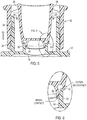
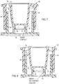
- the first, sealed and second, dispensing positions of the moveable tip 22 are respectively illustrated in Figures 3 and 4 .
- the inner sealing plug 26 and sealing sleeve 32 of the moveable tip are in sealing engagement with the sealing collar 20 of the closure shell.
- the sealing plug 26 and the sealing sleeve 32 are moved out of sealing engagement with the sealing collar 20 of the closure shell.
- One of the sealing collar 20 and the moveable tip 22 defines at least one venting projection 34 engageable with the other one of the sealing collar 20 and the moveable tip 22, after the movable tip is moved out of the first, sealed position toward the second, dispensing position.
- the interior surface of the sealing collar 20 of the closure shell defines at least one venting projection 34 engageable with the sealing plug 26 of the moveable tip, after the moveable tip is initially moved out of its first, sealed position towards its second, dispensing position.
- the sealing sleeve 32 of the moveable tip has moved out of sealing engagement with the sealing collar 20 of the closure shell.
- sealing engagement between the sealing plug 26 and the interior of sealing collar 20 is maintained, while the outer seal provided by sealing sleeve 32 is lost as the outer seal is moved out of engagement with the exterior surface of sealing collar 20.
- internal pressure within the associated container is decreased to the pressure level that can be maintained by the inner sealing engagement between the sealing plug 26 and the interior of sealing collar 20.
- sealing plug 26 only maintains contact with the one or more venting projections 34 provided on the interior surface of sealing collar 20. Gas pressure from within the associated container can vent, while foaming or liquid splash from within the container is desirably avoided.
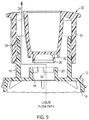
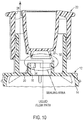
- Figures 11 and 12 illustrate a presently preferred configuration of the closure shell, including a plurality of the venting projections 34 provided in circumferentially spaced relationship on the interior surface of sealing collar 20 of the closure shell.
- the circumferentially spaced projections 34 remain in contact with the sealing plug 26 as the moveable tip 22 is initially moved from its first, sealed position, towards its second, dispensing position. This provides the desired pre-venting action for the present closure assembly.
- the sealing plug 26 of the moveable tip 22 has an axial length greater than the axial length of the sealing sleeve 32.
- this configuration of the sealing plug 26 and the sealing sleeve 32 acts to maintain engagement of the sealing plug 26 with sealing collar 20 after sealing sleeve 32 has moved out of sealing engagement with the sealing collar 20.
- This configuration is presently preferred, but the sealing regions of the closure assembly can be otherwise configured to achieve the desired pre-venting of internal gas pressure.
- sealing cooperation between the sealing plug 26 and the sealing collar 20 of the closure shell is enhanced by the preferred configuration of the sealing collar to include an outwardly flared, chamfered region at its interior surface for receiving the sealing plug 26.
- the circumferentially spaced venting projections 34 are positioned on the chamfered region of the sealing collar.
- one of the closure shell 12 and the movable tip 22 includes a detent projection 36 for cooperation with the other one of the closure shell 12 and the movable tip 22 for releasably retaining said movable tip in the first, sealed position on said closure shell.
- the moveable tip 22 includes an annular detent 38, engageable with a suitable annular recessed defined by mounting collar 16, when the moveable tip is in its first, sealed position. The detent thus desirably acts to releaseably maintain the moveable tip in its first position.
- the flow opening 28 defined by the moveable tip is positioned radially outwardly of the dispensing opening 18 defined by the closure shell.
- the one or more flow openings 28 of the moveable tip are not in the same axis as the sealing region of the closure assembly.
- liquid product from within the container does not have a direct flow path from the sealing region to the flow openings, and thus needs to change direction during flow (e.g., flow at 90° angles).
- the present invention provides a versatile arrangement for effecting convenient dispensing of product from a container, while minimizing undesired liquid splashing, foaming, or the like.
- the flow region 30 between the mounting sleeve 24 and the inner sealing plug 26 can be varied, as may be desired, so that the liquid flowing from the container must fill the flow region before being discharged through flow openings 28.
- the sealing region of the closure assembly is defined by the interior and exterior surfaces of the sealing collar 20 on the closure shell 12, and the "double sealing lips" provided on the moveable tip 22 in the form of sealing plug 26 and sealing sleeve 32.
- the shell due to material selection and/or closure geometry, is more rigid than the moveable tip 22, with the illustrated tip geometry thus providing the desired sealing between the components.
- sealing plug 26 effects sealing and is centered upon closing, with the external sealing, provided by sealing sleeve 32, enhancing sealing at relatively higher pressures.
- the illustrated arrangement desirably enhances resealing of the closure assembly attendant to opening and closing the moveable tip.
- Preferred embodiments of the invention include a dispensing closure assembly (10) according to claim 1, wherein said interior surface of said sealing collar (20) of said closure shell (12) defines at least one venting projection (34) engageable with said sealing plug (26) of said movable tip (22) after said movable tip is moved out of said first, sealed position toward said second, dispensing position, and after said sealing sleeve (32) of said movable tip (22) has moved out of sealing engagement with said sealing collar (20) of said closure shell.
- Yet another aspect includes a dispensing closure assembly (10) described above wherein said interior surface of said sealing collar (20) of said closure shell defines a plurality of said venting projections (34) positioned in spaced apart relationship on the interior surface of the sealing collar (20) .
- Yet another aspect includes a dispensing closure assembly (10) described above wherein said sealing plug (26) of said movable tip (22) has a hollow configuration.
- Yet another aspect includes a dispensing closure assembly (10) described above wherein said sealing plug (26) of said movable tip (22) has an axial length greater than an axial length of said sealing sleeve (32) of said movable tip (22).
- Yet another aspect includes a dispensing closure assembly (10) described above wherein one of said closure shell (12) and said movable tip (22) includes a detent projection (36) for cooperation with the other of said closure shell (12) and said movable tip (22) for releasably retaining said movable tip (22) in said first, sealed position on said closure shell (12).
- Yet another aspect includes a dispensing closure assembly (10) described above wherein said interior surface of said sealing collar (20) defines an outwardly flared, chamfered region for receiving said sealing plug (26) of said movable tip (22) in sealing engagement with the interior surface of the sealing collar (20), said venting projection (34) being positioned on said chamfered region.
Landscapes
- Engineering & Computer Science (AREA)
- Mechanical Engineering (AREA)
- Closures For Containers (AREA)
- Containers And Packaging Bodies Having A Special Means To Remove Contents (AREA)
Claims (8)
- Ausgabeverschlussanordnung (10), umfassend:einen Verschlussmantel (12) mit einem zylindrischen Körper (14) zum Aufsetzen auf einen dazugehörigen Behälter und einer zylindrischen Montagemanschette (16), die sich von dem zylindrischen Körper (14) aufwärts erstreckt, wobei der zylindrische Körper (14) mindestens eine mittige Ausgabeöffnung (18) definiert, durch die Produkt von dem Behälter durch den Verschlussmantel (12) fließen kann, wobei der Verschlussmantel (12) ferner eine Abdichtungsmanschette (20) beinhaltet, die einwärts von der Montagemanschette (16) positioniert ist und sich von dem zylindrischen Körper (14) des Verschlussmantels (12) aufwärts um die mittige Ausgabeöffnung (18) erstreckt, undeine bewegliche Spitze (22) zum Steuern eines Durchflusses durch die Ausgabeverschlussanordnung (10), wobei die bewegliche Spitze (22) eine äußere Montagehülse (24) zum gleitenden Aufsetzen auf eine Außenoberfläche der Montagemanschette (16) des Verschlussmantels (12) und einen inneren Abdichtungsstopfen (26), der einwärts von der äußeren Montagehülse (24) positioniert ist, zum abdichtenden Eingriff mit einer Innenoberfläche der Abdichtungsmanschette (20) des Verschlussmantels (12) aufweist,wobei die bewegliche Spitze (22) mindestens eine Durchflussöffnung (28) in Verbindung mit einer Durchflussregion (30) zwischen der äußeren Montagehülse (24) und dem inneren Abdichtungsstopfen (26) definiert,wobei die bewegliche Spitze (22) ferner eine Abdichtungshülse (32), die auswärts von dem Abdichtungsstopfen (26) positioniert ist, zum abdichtenden Eingriff mit der Abdichtungsmanschette (20) des Verschlussmantels (12) beinhaltet,wobei die bewegliche Spitze (22) beweglich ist zwischen: 1) einer ersten, abgedichteten Position, in der der Abdichtungsstopfen (26) und die Abdichtungshülse (32) der beweglichen Spitze (22) in Eingriff stehen und an der Abdichtungsmanschette (20) des Verschlussmantels (12) abdichten, um einen Durchfluss aus dem Behälter durch die Ausgabeverschlussanordnung (10) zu blockieren, und 2) einer zweiten, ausgebenden Position, in der sich der Abdichtungsstopfen (26) und die Abdichtungshülse (32) der beweglichen Spitze (22) nicht in abdichtendem Eingriff mit der Abdichtungsmanschette (20) des Verschlussmantels (12) befinden, um den Durchfluss von dem Behälter auswärts durch die von dem Verschlussmantel (12) definierte Ausgabeöffnung (18) in die von dem inneren Abdichtungsstopfen (26) der beweglichen Spitze (22) definierten Durchflussregion (30) und aus der durch die bewegliche Spitze definierte Durchflussöffnung (28) hinaus zu gestatten, wobei die von der beweglichen Spitze (22) definierte Durchflussöffnung (28) radial auswärts von der von dem Verschlussmantel (12) definierten Ausgabeöffnung (18) positioniert ist, dadurch gekennzeichnet, dass die Durchflussregion (30) ferner durch die äußere Montagehülse (24) definiert ist.
- Ausgabeverschlussanordnung (10) nach Anspruch 1, wobei eine von der Abdichtungsmanschette (20) und der beweglichen Spitze (22) mindestens einen Lüftungsvorsprung (34) definiert, der mit der anderen von der Abdichtungsmanschette (20) und der beweglichen Spitze (22) in Eingriff stehen kann, nachdem die bewegliche Spitze (22) aus der ersten, abgedichteten Position in die zweite, ausgebende Position bewegt wird.
- Ausgabeverschlussanordnung (10) nach Anspruch 1, wobei die Innenoberfläche der Abdichtungsmanschette (20) des Verschlussmantels (12) mindestens einen Lüftungsvorsprung (34) definiert, der mit dem Abdichtungsstopfen (26) der beweglichen Spitze (22) in Eingriff stehen kann, nachdem die bewegliche Spitze (22) aus der ersten, abgedichteten Position in die zweite, ausgebende Position bewegt wird und nachdem die Abdichtungshülse (32) der beweglichen Spitze (22) sich aus dem abdichtenden Eingriff mit der Abdichtungsmanschette (20) des Verschlussmantels (12) bewegt hat.
- Ausgabeverschlussanordnung (10) nach Anspruch 2, wobei die Innenoberfläche der Abdichtungsmanschette (20) des Verschlussmantels (12) mehrere der Lüftungsvorsprünge (34) definiert, die in beabstandeter Beziehung zueinander an der Innenoberfläche der Abdichtungsmanschette (20) positioniert sind.
- Ausgabeverschlussanordnung (10) nach Anspruch 1, wobei der Abdichtungsstopfen (26) der beweglichen Spitze (22) eine hohle Gestaltung aufweist.
- Ausgabeverschlussanordnung (10) nach Anspruch 1, wobei der Abdichtungsstopfen (26) der beweglichen Spitze (22) eine axiale Länge aufweist, die größer ist als eine axiale Länge der Abdichtungshülse (32) der beweglichen Spitze (22), angeordnet derart, dass während der öffnenden Bewegung der beweglichen Spitze (22) diese Gestaltung des Abdichtungsstopfens (26) und der Abdichtungshülse (32) dazu dient, einen Eingriff des Abdichtungsstopfens (26) mit der Abdichtungsmanschette (20) aufrechtzuerhalten, nachdem sich die Abdichtungshülse (32) aus dem abdichtenden Eingriff mit der Abdichtungsmanschette (20) bewegt hat.
- Ausgabeverschlussanordnung (10) nach Anspruch 1, wobei eines von dem Verschlussmantel (12) und der beweglichen Spitze (22) einen Haltevorsprung (36) zur Zusammenwirkung mit dem anderen von dem Verschlussmantel (12) und der beweglichen Spitze (22) beinhaltet, zum lösbaren Festhalten der beweglichen Spitze (22) in der ersten, abgedichteten Position an dem Verschlussmantel (12).
- Ausgabeverschlussanordnung (10) nach Anspruch 2, wobei die Innenoberfläche der Abdichtungsmanschette (20) eine auswärts aufgeweitete, abgeschrägte Region zum Aufnehmen des Abdichtungsstopfens (26) der beweglichen Spitze (22) in abdichtendem Eingriff mit der Innenoberfläche der Abdichtungsmanschette (20) definiert, wobei der Lüftungsvorsprung (34) an der abgeschrägten Region positioniert ist.
Applications Claiming Priority (2)
| Application Number | Priority Date | Filing Date | Title |
|---|---|---|---|
| US201461927238P | 2014-01-14 | 2014-01-14 | |
| PCT/US2015/011302 WO2015108906A1 (en) | 2014-01-14 | 2015-01-14 | Dispensing closure assembly with pre-venting |
Publications (3)
| Publication Number | Publication Date |
|---|---|
| EP3094571A1 EP3094571A1 (de) | 2016-11-23 |
| EP3094571A4 EP3094571A4 (de) | 2017-07-26 |
| EP3094571B1 true EP3094571B1 (de) | 2019-08-28 |
Family
ID=53520726
Family Applications (1)
| Application Number | Title | Priority Date | Filing Date |
|---|---|---|---|
| EP15737938.9A Active EP3094571B1 (de) | 2014-01-14 | 2015-01-14 | Abgabeverschlussanordnung mit vorabentlüftung |
Country Status (4)
| Country | Link |
|---|---|
| US (1) | US9290308B2 (de) |
| EP (1) | EP3094571B1 (de) |
| MX (1) | MX375197B (de) |
| WO (1) | WO2015108906A1 (de) |
Families Citing this family (8)
| Publication number | Priority date | Publication date | Assignee | Title |
|---|---|---|---|---|
| WO2015042518A1 (en) * | 2013-09-20 | 2015-03-26 | Closure Systems International Inc. | Anti-refill closure assembly |
| EP3094571B1 (de) * | 2014-01-14 | 2019-08-28 | Closure Systems International Inc. | Abgabeverschlussanordnung mit vorabentlüftung |
| GB201621054D0 (en) * | 2016-12-12 | 2017-01-25 | Gizmo Packaging Ltd | Closurewith spout and/or means for introducing two additives into a beverage container |
| US10407225B2 (en) | 2017-11-07 | 2019-09-10 | Closure Systems International Inc. | Closure and package that vents at high pressure |
| USD858284S1 (en) * | 2017-11-15 | 2019-09-03 | Gabrielle Studio, Inc | Cap for fragrance bottle |
| USD858283S1 (en) * | 2017-11-15 | 2019-09-03 | Gabrielle Studio, Inc. | Cap for fragrance bottle |
| US11053054B2 (en) * | 2018-08-03 | 2021-07-06 | Gateway Plastics, Inc. | Spout fitment and cap |
| CN110589218A (zh) * | 2019-10-25 | 2019-12-20 | 中山市华宝勒生活用品实业有限公司 | 一种便于倒取的盖组件 |
Family Cites Families (19)
| Publication number | Priority date | Publication date | Assignee | Title |
|---|---|---|---|---|
| US1861442A (en) * | 1929-08-28 | 1932-06-07 | Hammerstein Arthur | Self closing stopper for receptacles |
| US3834596A (en) * | 1973-07-11 | 1974-09-10 | Mennen Co | Bottle-closure structure |
| US4191315A (en) | 1977-03-03 | 1980-03-04 | Funke Ludwig F | Closure |
| CA1324345C (en) | 1988-03-17 | 1993-11-16 | James M. Beck | Adjustable metering closure cap |
| US5609276A (en) * | 1992-12-02 | 1997-03-11 | S. C. Johnson & Son, Inc. | Adjustable spray dispensing closure for containers |
| US5975369A (en) | 1997-06-05 | 1999-11-02 | Erie County Plastics Corporation | Resealable pushable container closure and cover therefor |
| US6311878B1 (en) * | 2000-01-07 | 2001-11-06 | Owens-Brockway Plastics Products Inc. | Dispensing package for fluent products |
| US20020074365A1 (en) * | 2000-12-14 | 2002-06-20 | Young John L. | Vented fluid container closure |
| US6997359B2 (en) * | 2001-09-12 | 2006-02-14 | Pepsico, Inc. | Bottle closure |
| US7066360B2 (en) * | 2003-11-05 | 2006-06-27 | Alcoa Closure Systems International | Push-pull container closure |
| DE102004055338A1 (de) | 2004-11-16 | 2006-05-18 | Alpla-Werke Alwin Lehner Gmbh & Co. Kg | Verschlusskappe |
| US7644843B1 (en) * | 2006-12-14 | 2010-01-12 | Rexam Closures And Containers Inc. | Reverse taper dispensing orifice seal |
| ITPD20080064A1 (it) | 2008-02-26 | 2009-08-27 | Acqua Minerale S Benedetto Spa | Struttura perfezionata di tappo asettico di tipo push-pull |
| US20100072231A1 (en) * | 2008-09-25 | 2010-03-25 | Bloom Kenneth S | Baffled Dispensing Closure |
| FR2937624B1 (fr) | 2008-10-24 | 2010-11-19 | Bericap | Bouchon a obturateur coulissant |
| CL2008003761A1 (es) * | 2008-12-17 | 2010-01-04 | The Tapa Company S A | Sistema de cierre para envases del tipo botella que permite dispensar hacia el interior un aditivo mantenido aislado, formado por una cubierta alargada con su extremo cerrado, un actuador con una pieza deslizante conica con una perforacion vertical, un cuerpo con un compartimiento central con un faldon hilado, y un contenedor con el aditivo. |
| IT1397513B1 (it) | 2009-12-14 | 2013-01-16 | Ferrari | Tappo migliorato per contenitori |
| CN203094727U (zh) | 2013-03-01 | 2013-07-31 | 宜昌崟锦包装有限责任公司 | 一种可靠密封瓶盖 |
| EP3094571B1 (de) * | 2014-01-14 | 2019-08-28 | Closure Systems International Inc. | Abgabeverschlussanordnung mit vorabentlüftung |
-
2015
- 2015-01-14 EP EP15737938.9A patent/EP3094571B1/de active Active
- 2015-01-14 MX MX2016009103A patent/MX375197B/es active IP Right Grant
- 2015-01-14 WO PCT/US2015/011302 patent/WO2015108906A1/en not_active Ceased
- 2015-01-14 US US14/596,442 patent/US9290308B2/en active Active
Non-Patent Citations (1)
| Title |
|---|
| None * |
Also Published As
| Publication number | Publication date |
|---|---|
| MX375197B (es) | 2025-03-06 |
| WO2015108906A1 (en) | 2015-07-23 |
| MX2016009103A (es) | 2016-09-09 |
| EP3094571A1 (de) | 2016-11-23 |
| US9290308B2 (en) | 2016-03-22 |
| US20150197380A1 (en) | 2015-07-16 |
| EP3094571A4 (de) | 2017-07-26 |
Similar Documents
| Publication | Publication Date | Title |
|---|---|---|
| US9290308B2 (en) | Dispensing closure assembly with pre-venting | |
| US9045269B2 (en) | Container closure having means for introducing an additive into the contents of the container | |
| US7588142B1 (en) | Additive delivery system closure | |
| US3439843A (en) | Liquid dispenser having a closure cap | |
| EP3655342B1 (de) | Veschluss mit einem aufsatz für einen behälterhals | |
| US3318496A (en) | Container closure with axial plug | |
| US5655685A (en) | Closure assembly for a container having a tamper-evident pouring spout closure member | |
| CN101233052B (zh) | 容器封闭组件及其与具有带外螺纹颈部的容器组合物 | |
| CN110062738B (zh) | 具有喷口的闭合件和用于将添加剂引入饮料容器的装置 | |
| US6698628B2 (en) | Extension for bottle dispenser, in particular for food products | |
| RU2660067C2 (ru) | Дозирующая крышка | |
| EP1796983B1 (de) | Ventil | |
| EP3538451B1 (de) | Ventilanordnung für druckbehälter in einer verschlussvorrichtung | |
| JP7418921B2 (ja) | 移行中栓キャップ | |
| JP2010070229A (ja) | コック式注出口栓 | |
| EP1746040A1 (de) | Verschluss für einen Behälter | |
| EP3823905B1 (de) | Abgabeverschluss mit entlüftungskanälen | |
| JP3211486U (ja) | プッシュプルクロージャーにおける又はプッシュプルクロージャーに関する改善 | |
| EP3424835B1 (de) | Deckel für eine lebensmittelverpackung | |
| JP2019116282A (ja) | 混合キャップ | |
| RU114668U1 (ru) | Закупоривающее устройство для бутылки с жидкостью | |
| EP2275359B1 (de) | Verschlusskappe | |
| WO2008042737A2 (en) | Dispensing closure for wet aseptic and low pressure applications | |
| US20170158385A1 (en) | Unitary dispenser assembly with break-away cap | |
| JP2009234640A (ja) | プラスチックキャップ |
Legal Events
| Date | Code | Title | Description |
|---|---|---|---|
| PUAI | Public reference made under article 153(3) epc to a published international application that has entered the european phase |
Free format text: ORIGINAL CODE: 0009012 |
|
| 17P | Request for examination filed |
Effective date: 20160704 |
|
| AK | Designated contracting states |
Kind code of ref document: A1 Designated state(s): AL AT BE BG CH CY CZ DE DK EE ES FI FR GB GR HR HU IE IS IT LI LT LU LV MC MK MT NL NO PL PT RO RS SE SI SK SM TR |
|
| AX | Request for extension of the european patent |
Extension state: BA ME |
|
| DAX | Request for extension of the european patent (deleted) | ||
| A4 | Supplementary search report drawn up and despatched |
Effective date: 20170626 |
|
| RIC1 | Information provided on ipc code assigned before grant |
Ipc: B65D 47/32 20060101AFI20170620BHEP Ipc: B65D 51/16 20060101ALI20170620BHEP Ipc: B65D 47/28 20060101ALI20170620BHEP |
|
| STAA | Information on the status of an ep patent application or granted ep patent |
Free format text: STATUS: EXAMINATION IS IN PROGRESS |
|
| 17Q | First examination report despatched |
Effective date: 20180515 |
|
| GRAP | Despatch of communication of intention to grant a patent |
Free format text: ORIGINAL CODE: EPIDOSNIGR1 |
|
| STAA | Information on the status of an ep patent application or granted ep patent |
Free format text: STATUS: GRANT OF PATENT IS INTENDED |
|
| INTG | Intention to grant announced |
Effective date: 20190424 |
|
| GRAS | Grant fee paid |
Free format text: ORIGINAL CODE: EPIDOSNIGR3 |
|
| GRAA | (expected) grant |
Free format text: ORIGINAL CODE: 0009210 |
|
| STAA | Information on the status of an ep patent application or granted ep patent |
Free format text: STATUS: THE PATENT HAS BEEN GRANTED |
|
| AK | Designated contracting states |
Kind code of ref document: B1 Designated state(s): AL AT BE BG CH CY CZ DE DK EE ES FI FR GB GR HR HU IE IS IT LI LT LU LV MC MK MT NL NO PL PT RO RS SE SI SK SM TR |
|
| REG | Reference to a national code |
Ref country code: GB Ref legal event code: FG4D |
|
| REG | Reference to a national code |
Ref country code: CH Ref legal event code: EP |
|
| REG | Reference to a national code |
Ref country code: CH Ref legal event code: NV Representative=s name: VALIPAT S.A. C/O BOVARD SA NEUCHATEL, CH |
|
| REG | Reference to a national code |
Ref country code: AT Ref legal event code: REF Ref document number: 1172129 Country of ref document: AT Kind code of ref document: T Effective date: 20190915 |
|
| REG | Reference to a national code |
Ref country code: IE Ref legal event code: FG4D |
|
| REG | Reference to a national code |
Ref country code: DE Ref legal event code: R096 Ref document number: 602015036713 Country of ref document: DE |
|
| REG | Reference to a national code |
Ref country code: NL Ref legal event code: MP Effective date: 20190828 |
|
| REG | Reference to a national code |
Ref country code: LT Ref legal event code: MG4D |
|
| PG25 | Lapsed in a contracting state [announced via postgrant information from national office to epo] |
Ref country code: SE Free format text: LAPSE BECAUSE OF FAILURE TO SUBMIT A TRANSLATION OF THE DESCRIPTION OR TO PAY THE FEE WITHIN THE PRESCRIBED TIME-LIMIT Effective date: 20190828 Ref country code: HR Free format text: LAPSE BECAUSE OF FAILURE TO SUBMIT A TRANSLATION OF THE DESCRIPTION OR TO PAY THE FEE WITHIN THE PRESCRIBED TIME-LIMIT Effective date: 20190828 Ref country code: NL Free format text: LAPSE BECAUSE OF FAILURE TO SUBMIT A TRANSLATION OF THE DESCRIPTION OR TO PAY THE FEE WITHIN THE PRESCRIBED TIME-LIMIT Effective date: 20190828 Ref country code: NO Free format text: LAPSE BECAUSE OF FAILURE TO SUBMIT A TRANSLATION OF THE DESCRIPTION OR TO PAY THE FEE WITHIN THE PRESCRIBED TIME-LIMIT Effective date: 20191128 Ref country code: BG Free format text: LAPSE BECAUSE OF FAILURE TO SUBMIT A TRANSLATION OF THE DESCRIPTION OR TO PAY THE FEE WITHIN THE PRESCRIBED TIME-LIMIT Effective date: 20191128 Ref country code: LT Free format text: LAPSE BECAUSE OF FAILURE TO SUBMIT A TRANSLATION OF THE DESCRIPTION OR TO PAY THE FEE WITHIN THE PRESCRIBED TIME-LIMIT Effective date: 20190828 Ref country code: PT Free format text: LAPSE BECAUSE OF FAILURE TO SUBMIT A TRANSLATION OF THE DESCRIPTION OR TO PAY THE FEE WITHIN THE PRESCRIBED TIME-LIMIT Effective date: 20191230 Ref country code: FI Free format text: LAPSE BECAUSE OF FAILURE TO SUBMIT A TRANSLATION OF THE DESCRIPTION OR TO PAY THE FEE WITHIN THE PRESCRIBED TIME-LIMIT Effective date: 20190828 |
|
| PG25 | Lapsed in a contracting state [announced via postgrant information from national office to epo] |
Ref country code: AL Free format text: LAPSE BECAUSE OF FAILURE TO SUBMIT A TRANSLATION OF THE DESCRIPTION OR TO PAY THE FEE WITHIN THE PRESCRIBED TIME-LIMIT Effective date: 20190828 Ref country code: ES Free format text: LAPSE BECAUSE OF FAILURE TO SUBMIT A TRANSLATION OF THE DESCRIPTION OR TO PAY THE FEE WITHIN THE PRESCRIBED TIME-LIMIT Effective date: 20190828 Ref country code: LV Free format text: LAPSE BECAUSE OF FAILURE TO SUBMIT A TRANSLATION OF THE DESCRIPTION OR TO PAY THE FEE WITHIN THE PRESCRIBED TIME-LIMIT Effective date: 20190828 Ref country code: GR Free format text: LAPSE BECAUSE OF FAILURE TO SUBMIT A TRANSLATION OF THE DESCRIPTION OR TO PAY THE FEE WITHIN THE PRESCRIBED TIME-LIMIT Effective date: 20191129 Ref country code: IS Free format text: LAPSE BECAUSE OF FAILURE TO SUBMIT A TRANSLATION OF THE DESCRIPTION OR TO PAY THE FEE WITHIN THE PRESCRIBED TIME-LIMIT Effective date: 20191228 Ref country code: RS Free format text: LAPSE BECAUSE OF FAILURE TO SUBMIT A TRANSLATION OF THE DESCRIPTION OR TO PAY THE FEE WITHIN THE PRESCRIBED TIME-LIMIT Effective date: 20190828 |
|
| REG | Reference to a national code |
Ref country code: AT Ref legal event code: MK05 Ref document number: 1172129 Country of ref document: AT Kind code of ref document: T Effective date: 20190828 |
|
| PG25 | Lapsed in a contracting state [announced via postgrant information from national office to epo] |
Ref country code: TR Free format text: LAPSE BECAUSE OF FAILURE TO SUBMIT A TRANSLATION OF THE DESCRIPTION OR TO PAY THE FEE WITHIN THE PRESCRIBED TIME-LIMIT Effective date: 20190828 |
|
| PG25 | Lapsed in a contracting state [announced via postgrant information from national office to epo] |
Ref country code: RO Free format text: LAPSE BECAUSE OF FAILURE TO SUBMIT A TRANSLATION OF THE DESCRIPTION OR TO PAY THE FEE WITHIN THE PRESCRIBED TIME-LIMIT Effective date: 20190828 Ref country code: PL Free format text: LAPSE BECAUSE OF FAILURE TO SUBMIT A TRANSLATION OF THE DESCRIPTION OR TO PAY THE FEE WITHIN THE PRESCRIBED TIME-LIMIT Effective date: 20190828 Ref country code: IT Free format text: LAPSE BECAUSE OF FAILURE TO SUBMIT A TRANSLATION OF THE DESCRIPTION OR TO PAY THE FEE WITHIN THE PRESCRIBED TIME-LIMIT Effective date: 20190828 Ref country code: DK Free format text: LAPSE BECAUSE OF FAILURE TO SUBMIT A TRANSLATION OF THE DESCRIPTION OR TO PAY THE FEE WITHIN THE PRESCRIBED TIME-LIMIT Effective date: 20190828 Ref country code: AT Free format text: LAPSE BECAUSE OF FAILURE TO SUBMIT A TRANSLATION OF THE DESCRIPTION OR TO PAY THE FEE WITHIN THE PRESCRIBED TIME-LIMIT Effective date: 20190828 Ref country code: EE Free format text: LAPSE BECAUSE OF FAILURE TO SUBMIT A TRANSLATION OF THE DESCRIPTION OR TO PAY THE FEE WITHIN THE PRESCRIBED TIME-LIMIT Effective date: 20190828 |
|
| PGFP | Annual fee paid to national office [announced via postgrant information from national office to epo] |
Ref country code: GB Payment date: 20200129 Year of fee payment: 6 Ref country code: IE Payment date: 20200121 Year of fee payment: 6 |
|
| PG25 | Lapsed in a contracting state [announced via postgrant information from national office to epo] |
Ref country code: SM Free format text: LAPSE BECAUSE OF FAILURE TO SUBMIT A TRANSLATION OF THE DESCRIPTION OR TO PAY THE FEE WITHIN THE PRESCRIBED TIME-LIMIT Effective date: 20190828 Ref country code: IS Free format text: LAPSE BECAUSE OF FAILURE TO SUBMIT A TRANSLATION OF THE DESCRIPTION OR TO PAY THE FEE WITHIN THE PRESCRIBED TIME-LIMIT Effective date: 20200224 Ref country code: CZ Free format text: LAPSE BECAUSE OF FAILURE TO SUBMIT A TRANSLATION OF THE DESCRIPTION OR TO PAY THE FEE WITHIN THE PRESCRIBED TIME-LIMIT Effective date: 20190828 Ref country code: SK Free format text: LAPSE BECAUSE OF FAILURE TO SUBMIT A TRANSLATION OF THE DESCRIPTION OR TO PAY THE FEE WITHIN THE PRESCRIBED TIME-LIMIT Effective date: 20190828 |
|
| PGFP | Annual fee paid to national office [announced via postgrant information from national office to epo] |
Ref country code: LU Payment date: 20200128 Year of fee payment: 6 Ref country code: BE Payment date: 20200128 Year of fee payment: 6 Ref country code: CH Payment date: 20200127 Year of fee payment: 6 |
|
| REG | Reference to a national code |
Ref country code: DE Ref legal event code: R097 Ref document number: 602015036713 Country of ref document: DE |
|
| PGFP | Annual fee paid to national office [announced via postgrant information from national office to epo] |
Ref country code: FR Payment date: 20200128 Year of fee payment: 6 |
|
| PLBE | No opposition filed within time limit |
Free format text: ORIGINAL CODE: 0009261 |
|
| STAA | Information on the status of an ep patent application or granted ep patent |
Free format text: STATUS: NO OPPOSITION FILED WITHIN TIME LIMIT |
|
| PG2D | Information on lapse in contracting state deleted |
Ref country code: IS |
|
| PGFP | Annual fee paid to national office [announced via postgrant information from national office to epo] |
Ref country code: DE Payment date: 20200327 Year of fee payment: 6 |
|
| 26N | No opposition filed |
Effective date: 20200603 |
|
| PG25 | Lapsed in a contracting state [announced via postgrant information from national office to epo] |
Ref country code: SI Free format text: LAPSE BECAUSE OF FAILURE TO SUBMIT A TRANSLATION OF THE DESCRIPTION OR TO PAY THE FEE WITHIN THE PRESCRIBED TIME-LIMIT Effective date: 20190828 Ref country code: MC Free format text: LAPSE BECAUSE OF FAILURE TO SUBMIT A TRANSLATION OF THE DESCRIPTION OR TO PAY THE FEE WITHIN THE PRESCRIBED TIME-LIMIT Effective date: 20190828 |
|
| REG | Reference to a national code |
Ref country code: DE Ref legal event code: R119 Ref document number: 602015036713 Country of ref document: DE |
|
| REG | Reference to a national code |
Ref country code: CH Ref legal event code: PL |
|
| GBPC | Gb: european patent ceased through non-payment of renewal fee |
Effective date: 20210114 |
|
| PG25 | Lapsed in a contracting state [announced via postgrant information from national office to epo] |
Ref country code: LU Free format text: LAPSE BECAUSE OF NON-PAYMENT OF DUE FEES Effective date: 20210114 |
|
| REG | Reference to a national code |
Ref country code: BE Ref legal event code: MM Effective date: 20210131 |
|
| PG25 | Lapsed in a contracting state [announced via postgrant information from national office to epo] |
Ref country code: FR Free format text: LAPSE BECAUSE OF NON-PAYMENT OF DUE FEES Effective date: 20210131 |
|
| PG25 | Lapsed in a contracting state [announced via postgrant information from national office to epo] |
Ref country code: GB Free format text: LAPSE BECAUSE OF NON-PAYMENT OF DUE FEES Effective date: 20210114 Ref country code: LI Free format text: LAPSE BECAUSE OF NON-PAYMENT OF DUE FEES Effective date: 20210131 Ref country code: CH Free format text: LAPSE BECAUSE OF NON-PAYMENT OF DUE FEES Effective date: 20210131 Ref country code: DE Free format text: LAPSE BECAUSE OF NON-PAYMENT OF DUE FEES Effective date: 20210803 |
|
| PG25 | Lapsed in a contracting state [announced via postgrant information from national office to epo] |
Ref country code: IE Free format text: LAPSE BECAUSE OF NON-PAYMENT OF DUE FEES Effective date: 20210114 |
|
| PG25 | Lapsed in a contracting state [announced via postgrant information from national office to epo] |
Ref country code: MT Free format text: LAPSE BECAUSE OF FAILURE TO SUBMIT A TRANSLATION OF THE DESCRIPTION OR TO PAY THE FEE WITHIN THE PRESCRIBED TIME-LIMIT Effective date: 20190828 Ref country code: CY Free format text: LAPSE BECAUSE OF FAILURE TO SUBMIT A TRANSLATION OF THE DESCRIPTION OR TO PAY THE FEE WITHIN THE PRESCRIBED TIME-LIMIT Effective date: 20190828 |
|
| PG25 | Lapsed in a contracting state [announced via postgrant information from national office to epo] |
Ref country code: MK Free format text: LAPSE BECAUSE OF FAILURE TO SUBMIT A TRANSLATION OF THE DESCRIPTION OR TO PAY THE FEE WITHIN THE PRESCRIBED TIME-LIMIT Effective date: 20190828 |
|
| PG25 | Lapsed in a contracting state [announced via postgrant information from national office to epo] |
Ref country code: BE Free format text: LAPSE BECAUSE OF NON-PAYMENT OF DUE FEES Effective date: 20210131 |