EP3095154B1 - Fixation d'une antenne de toit sur un toit de carrosserie - Google Patents
Fixation d'une antenne de toit sur un toit de carrosserie Download PDFInfo
- Publication number
- EP3095154B1 EP3095154B1 EP15701133.9A EP15701133A EP3095154B1 EP 3095154 B1 EP3095154 B1 EP 3095154B1 EP 15701133 A EP15701133 A EP 15701133A EP 3095154 B1 EP3095154 B1 EP 3095154B1
- Authority
- EP
- European Patent Office
- Prior art keywords
- fastening
- roof
- claw
- antenna
- roof antenna
- Prior art date
- Legal status (The legal status is an assumption and is not a legal conclusion. Google has not performed a legal analysis and makes no representation as to the accuracy of the status listed.)
- Active
Links
Images



Classifications
-
- H—ELECTRICITY
- H01—ELECTRIC ELEMENTS
- H01Q—ANTENNAS, i.e. RADIO AERIALS
- H01Q1/00—Details of, or arrangements associated with, antennas
- H01Q1/27—Adaptation for use in or on movable bodies
- H01Q1/32—Adaptation for use in or on road or rail vehicles
- H01Q1/325—Adaptation for use in or on road or rail vehicles characterised by the location of the antenna on the vehicle
- H01Q1/3275—Adaptation for use in or on road or rail vehicles characterised by the location of the antenna on the vehicle mounted on a horizontal surface of the vehicle, e.g. on roof, hood, trunk
-
- H—ELECTRICITY
- H01—ELECTRIC ELEMENTS
- H01Q—ANTENNAS, i.e. RADIO AERIALS
- H01Q1/00—Details of, or arrangements associated with, antennas
- H01Q1/12—Supports; Mounting means
- H01Q1/1207—Supports; Mounting means for fastening a rigid aerial element
- H01Q1/1214—Supports; Mounting means for fastening a rigid aerial element through a wall
-
- F—MECHANICAL ENGINEERING; LIGHTING; HEATING; WEAPONS; BLASTING
- F16—ENGINEERING ELEMENTS AND UNITS; GENERAL MEASURES FOR PRODUCING AND MAINTAINING EFFECTIVE FUNCTIONING OF MACHINES OR INSTALLATIONS; THERMAL INSULATION IN GENERAL
- F16B—DEVICES FOR FASTENING OR SECURING CONSTRUCTIONAL ELEMENTS OR MACHINE PARTS TOGETHER, e.g. NAILS, BOLTS, CIRCLIPS, CLAMPS, CLIPS OR WEDGES; JOINTS OR JOINTING
- F16B13/00—Dowels or other devices fastened in walls or the like by inserting them in holes made therein for that purpose
- F16B13/04—Dowels or other devices fastened in walls or the like by inserting them in holes made therein for that purpose with parts gripping in the hole or behind the reverse side of the wall after inserting from the front
- F16B13/08—Dowels or other devices fastened in walls or the like by inserting them in holes made therein for that purpose with parts gripping in the hole or behind the reverse side of the wall after inserting from the front with separate or non-separate gripping parts moved into their final position in relation to the body of the device without further manual operation
- F16B13/0833—Dowels or other devices fastened in walls or the like by inserting them in holes made therein for that purpose with parts gripping in the hole or behind the reverse side of the wall after inserting from the front with separate or non-separate gripping parts moved into their final position in relation to the body of the device without further manual operation with segments or fingers expanding or tilting into an undercut hole
Definitions
- the invention relates to a roof antenna with a base plate and an outer hood for arrangement on a roof of a vehicle, the roof antenna having a fastening mechanism which comprises a fastening screw and a fastening claw interacting therewith, according to the features of the preamble of patent claim 1.
- Such generic roof antennas which are arranged and fixed on a roof of a vehicle, are known.
- the fastening claw ensures that the roof antenna is placed on the roof and is arranged in a pre-latched position on the roof.
- the roof antenna is passed through an opening in the roof with a partial area of the fastening mechanism, so that a base plate of the roof antenna comes to rest on the roof in a plane-parallel manner with or without a spacing.
- the fastening screw can be actuated from the interior of the vehicle in order to arrange the roof antenna in its final position on the roof of the vehicle and fix it immovably.
- the invention is based on the object of providing a roof antenna for arrangement on a roof of a vehicle, which is further improved in terms of its installation compared to known roof antennas.
- the base plate of the roof antenna forms a counter-holder to which the fastening claw is fixed, the fastening claw forming a receiving area for the fastening screw which is free before the fastening screw is inserted and is filled by the latter after the fastening screw has been inserted.
- the advantage is initially retained that the roof antenna can be arranged with part of the fastening area from above through an opening in the roof and fixed in a pre-latching position by means of the fastening claw. After this has been done, the roof antenna can finally be fixed immovably on the roof of the vehicle by actuating the fastening screw.
- the fastening screw is brought into operative connection with the counter-holder in an advantageous manner. Due to the fact that the fastening screw does not initially fill the receiving area of the fastening claw, it is possible for the fastening claw to be compressed and then expanded when it is passed through the opening in the roof. The fastening claw grips the underside of the roof so that the roof antenna is pre-locked.
- the fastening screw Only now is it possible to bring the fastening screw into operative connection with the counter-holder of the base plate, so that the receiving area in the fastening claw is filled by the fastening screw.
- This has two advantages, namely, on the one hand, the operative connection between the counter-holder and the fastening screw fixes the roof antenna on the roof and, on the other hand, it prevents the fastening claw from being pressed together again in order to prevent the roof antenna from moving out of its once immovable position can detach again from the roof. It is particularly advantageous if the fastening screw has an external thread and a screw head, with the screw head partially or completely filling the receiving area of the fastening claw.
- the counter-holder of the base plate has an internal thread that corresponds to the external thread of the fastening screw, so that the fastening screw can be screwed into the counter-holder quickly, easily and easily through this screw connection, and at the same time the fastening claw is fixed in its final seat on the underside of the roof and the counter-holder .
- the fastening claw has at least one latching hook, preferably two latching hooks arranged opposite one another, at an open end of the receiving area.
- the at least one latching hook ensures that the roof antenna is fixed in a pre-latched position in relation to the roof when the fastening claw has been passed through the opening in the roof and the at least one latching hook prevents the roof antenna from being pulled out of the opening again .
- the at least one latching hook has an electrical function when both the roof and the fastening claw with the at least one latching hook are made of a metallic material.
- the operative connection of the fastening screw and counter-holder on the base plate causes the at least one latching hook to be pressed against the underside of the roof and comes to rest against the underside of the roof, as a result of which an electrical contact is created.
- the underside of the roof is provided with a coating, for example paint
- the at least one latching hook is moved relative to the underside by the operative connection between the fastening screw and counter-holder, as a result of which the coating is removed and direct metallic and therefore electrical contact is made will be produced.
- a contact is required, for example, for a ground connection for the purpose of shielding the roof antenna.
- the counter-holder of the base plate forms a free space for receiving a part of the fastening claw. If the fastening screw is brought into operative connection with the counter-holder (in particular, the fastening screw is screwed into the counter-holder), a partial area of the fastening claw is thereby deformed, with the deformed area of the fastening claw in particular having space in the free space of the counter-holder to expand.
- the axial extent of the fastening claw in particular the axial extent between the contact surface of the at least one latching hook on the underside of the roof and the end of the fastening claw with which it is fastened to the counter-holder, can change in order to to compensate for different thicknesses of the roof.
- FIG. 1 shows, as well as shown in detail, an antenna arrangement of a vehicle.
- a roof antenna with the reference number 1 is arranged and fixed on a roof 2 of the vehicle 2, not shown in detail.
- the roof antenna 1 has, for example, an outer hood 3 in the usual form, with a printed circuit board 4 being arranged below the outer hood 3 .
- the antenna elements that are usually present for sending and/or receiving high-frequency signals, such as for telephone, radio, television, GPS and the like.
- the circuit board 4 is shown at a distance from a base plate 5 of the roof antenna 1 .
- an antenna rod 6 with a further antenna element (rod antenna) can, but does not have to, be present.
- the antenna arrangement further comprises an opening 7 in the roof 2 and a fastening mechanism 8 which, as will be described below, comprises a fastening screw and a fastening claw.
- the inside figure 1 Structure of the antenna arrangement shown with the roof antenna 1 is an example.
- the illustrated internal structure of the roof antenna below the outer hood 3 is an example and can vary.
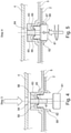
- FIGs 2 to 6 the method for mounting the roof antenna 1 on the roof 2 is shown in individual steps.
- the roof antenna 1 according to figure 1 in the following Figures 2 to 6 shown in detail in the areas around the fastening mechanism 8 including the areas of the base plate 5 and the printed circuit board 4 surrounding this area.
- figure 2 shows the first assembly step, in which the roof 2 has the opening 7 and the roof antenna 1 is prepared for carrying the fastening claw 2, which is arranged captively on the base plate 5, through the opening 7.
- the details of the special configuration of the fastening screw 81, the fastening claw 82 and the base plate 5 are discussed in more detail below in order to describe their respective function.
- FIG 3 the next step is shown, in which the fastening claw 82 is passed through the opening 7 .
- the at least one latching hook 88 here the two oppositely arranged latching hooks 88, is pressed together in the direction of the arrow shown. In this state it is not possible for the fastening screw 81 , more precisely its screw head, to fill a receiving area 87 of the fastening claw 82 .
- figure 4 shows the next step, namely that the fastening claw has been passed through the opening 7 so far that the ends of the fastening claw 82 with the latching hooks widen again and quasi release the receiving area 87 for the head of the fastening screw.
- the plane-parallel surface of the latching hooks 88 is aligned at a distance from the underside of the roof 2 . It is also conceivable that the underside of the roof 2 already comes into contact with the corresponding surface of the latching hooks 88. In this state it is possible to bring the fastening screw 81 into an operative connection with the base plate 5, but this is not yet the case in this assembly step the case is.
- FIG 5 is shown that due to the release of the receiving area 87 of the fastening claw 82, it is possible to bring the fastening screw 81 into operative connection with the base plate 5. This can be carried out by a Screw connection, as explained below, take place. However, it is also conceivable that other connection options, such as snap-in, snap-in or press-in connections or the like, can be considered.
- the fastening screw 81 is brought into operative connection with the floor panel 5 as follows.
- the base plate 5 has a counter-holder 83 which has an internal thread 84 .
- the fastening screw 81 has an external thread 85 starting from its screw head, which is not designated in any more detail.
- the fastening screw 81 can be screwed with its internal thread 84 into the external thread 85 of the counter-holder 83 of the base plate 5. Due to an angled area of the respective claw of the fastening claw 82, the underside of the screw head comes into contact with this angled area.
- figure 5 this is in figure 5 shown. That means that in figure 4 the roof antenna 1 was arranged pre-locked in its position on the roof 2 and now from the further assembly step, which is figure 5 is shown, in their immovable position on the roof 2 through the further process steps of figure 5 after figure 6 can be set. Namely, based on the mounting position as shown in figure 5 is shown, the fastening screw 81 is screwed further into the counter-holder 83 of the base plate 5, the fastening claw 82 is taken along axially in the direction of the underside of the roof 2 (and at the same time axially in the direction of the underside of the base plate 5). This takes place until the contact surface of the latching hooks 88 comes to rest on the underside of the roof 2 .
- the fastening screw 81 is not yet in its final position. Because by screwing the fastening screw 81 further into the counter-holder 83, a claw area 86, which extends from the counter-holder 83, is deformed and moved into a free space 89 of the counter-holder 83. Through this process, the roof antenna 1 is immovably arranged and fixed on the upper side of the roof 2 . By deforming the claw area 86 in the free space 89 of the counter-holder 83, tolerances and, above all, different thicknesses of the roof 2 can be compensated. Alternatively or additionally, it is possible to apply a defined tightening torque to the fastening screw 81 by geometrically matching the fastening claw 82 to the inner geometry of the counter-holder 83 set. This ensures that the roof antenna 1 is fixed on the roof 2 with such forces that it is held in an immovable position without damage to the elements involved, in particular within the fastening mechanism 8 or possibly also to parts of the vehicle.
- the final assembly step is thus shown, in which the fastening screw 81 is screwed with its internal thread 84 into the external thread 85 of the counter-holder 83 to such an extent that the base plate 5 of the roof antenna 1 is arranged and fixed in its desired position on the roof 2.
- the claw area 86 of the fastening claw 82 can, but does not have to, have been deformed within the free space 89 of the counter-holder 83 .
- the printed circuit board 4 arranged plane-parallel at a distance from the base plate 5 can have a corresponding opening.
- the receiving area 87 of the fastening claw 82 is filled by the head of the fastening screw 81, so that this prevents the end regions of the fastening claw 82 with their latching hooks 88 from being able to shift inwards again from their position, as is the case in the assembly step according to FIG figure 3 was the case.
- the roof antenna 1 is also advantageously fixed under pretension within the free space 89 of the counter-holder 83 due to the deformation of the claw areas 86 .
Landscapes
- Engineering & Computer Science (AREA)
- Remote Sensing (AREA)
- Support Of Aerials (AREA)
Claims (5)
- Antenne de toit (1) comprenant une plaque de base (5) et un capot extérieur (3) afin d'être disposée sur un toit (2) d'un véhicule, l'antenne de toit (1) comportant un mécanisme de fixation (8) qui comprend une vis de fixation (81) et une griffe de fixation (82) coopérant avec celle-ci, la plaque de base (5) formant un contre-support (83) auquel est fixée la griffe de fixation (82) et la griffe de fixation (82) formant une zone de réception (87) destinée à la vis de fixation (81), caractérisée en ce que la zone de réception (87) est libre avant l'insertion de la vis de fixation (81) de sorte qu'il soit possible de comprimer la griffe de fixation (82) et la zone de réception (87) est remplie par la vis de fixation (81) après que celle-ci a été insérée de sorte que la griffe de fixation (82) ne puisse pas être comprimée.
- Antenne de toit (1) selon la revendication 1, caractérisée en ce que la griffe de fixation (82) comporte au moins un crochet d'encliquetage (88) à une extrémité ouverte de la zone de réception (87).
- Antenne de toit (1) selon la revendication 2, caractérisée en ce que la griffe de fixation (82) comporte deux crochets d'encliquetage (88) disposés face à face à une extrémité ouverte de la zone de réception (87).
- Antenne de toit (1) selon l'une des revendications précédentes, caractérisée en ce que le contre-support (83) de la plaque de base (5) forme un espace libre (89) destiné à recevoir une partie de la griffe de fixation (82).
- Ensemble formant antenne d'un véhicule, ledit ensemble comportant une antenne de toit (1) selon l'une des revendications précédentes, l'antenne de toit (1) étant disposée et fixée sur un toit (2) du véhicule à l'aide du mécanisme de fixation (8).
Applications Claiming Priority (2)
| Application Number | Priority Date | Filing Date | Title |
|---|---|---|---|
| DE102014200853 | 2014-01-17 | ||
| PCT/EP2015/050755 WO2015107146A1 (fr) | 2014-01-17 | 2015-01-16 | Fixation d'une antenne de toit sur un toit de carrosserie |
Publications (2)
| Publication Number | Publication Date |
|---|---|
| EP3095154A1 EP3095154A1 (fr) | 2016-11-23 |
| EP3095154B1 true EP3095154B1 (fr) | 2022-03-16 |
Family
ID=52396664
Family Applications (1)
| Application Number | Title | Priority Date | Filing Date |
|---|---|---|---|
| EP15701133.9A Active EP3095154B1 (fr) | 2014-01-17 | 2015-01-16 | Fixation d'une antenne de toit sur un toit de carrosserie |
Country Status (6)
| Country | Link |
|---|---|
| US (1) | US10062959B2 (fr) |
| EP (1) | EP3095154B1 (fr) |
| CN (1) | CN105917520B (fr) |
| DE (1) | DE102015100634A1 (fr) |
| HK (1) | HK1223742A1 (fr) |
| WO (1) | WO2015107146A1 (fr) |
Cited By (1)
| Publication number | Priority date | Publication date | Assignee | Title |
|---|---|---|---|---|
| US20230008080A1 (en) * | 2021-07-08 | 2023-01-12 | Robert Bosch Gmbh | Radar system for surroundings detection of a motor vehicle |
Families Citing this family (10)
| Publication number | Priority date | Publication date | Assignee | Title |
|---|---|---|---|---|
| WO2016188896A1 (fr) | 2015-05-22 | 2016-12-01 | Hirschmann Car Communication Gmbh | Antenne de toit dotée d'une plaque de base dépourvue de joint en caoutchouc, destinée à différentes courbures de toit |
| EP3443615B1 (fr) * | 2016-04-12 | 2023-08-23 | Valeo Comfort and Driving Assistance | Module électronique pour véhicule automobile |
| JP6941631B2 (ja) | 2017-02-10 | 2021-09-29 | 株式会社ヨコオ | アンテナ取付装置 |
| EP3747185B1 (fr) * | 2018-01-30 | 2022-12-14 | Hirschmann Car Communication Gmbh | Antenne de toit d'un véhicule avec caméra de recul |
| US12104635B2 (en) | 2020-05-26 | 2024-10-01 | Harada Industry Co., Ltd. | Roof-mounted antenna mounting structure |
| CN112151942A (zh) * | 2020-10-19 | 2020-12-29 | 惠州硕贝德汽车智联科技有限公司 | 一种具有预安装结构的鲨鱼鳍天线 |
| CN112606773A (zh) * | 2020-12-28 | 2021-04-06 | 嵊州市兰花电器科技有限公司 | 一种汽车用的天线总成 |
| EP4396466B1 (fr) * | 2021-08-31 | 2026-03-04 | AUMOVIO Germany GmbH | Agencement de fixation d'un boîtier d'appareil d'un appareil sur une tôle de véhicule d'un véhicule à moteur ainsi que véhicule à moteur et appareil |
| CN118104069A (zh) * | 2021-10-28 | 2024-05-28 | 株式会社友华 | 连接端子以及天线装置 |
| CN114335995B (zh) * | 2021-12-29 | 2025-02-18 | 深圳市道通科技股份有限公司 | 一种具有可拆卸天线结构的装置 |
Family Cites Families (10)
| Publication number | Priority date | Publication date | Assignee | Title |
|---|---|---|---|---|
| US7004666B2 (en) * | 2001-10-09 | 2006-02-28 | Tyco Electronics Corporation | Quick-attach automotive antenna mounting assembly |
| US6714171B2 (en) * | 2002-06-14 | 2004-03-30 | Centurion Wireless Technologies, Inc. | Antenna mounting apparatuses and methods |
| US20080012776A1 (en) * | 2005-10-22 | 2008-01-17 | Hirschmann Car Communication Gmbh | Method of mounting and dismounting an antenna on a vehicle roof |
| DE102006009660B4 (de) * | 2006-03-02 | 2012-03-08 | Blaupunkt Antenna Systems Gmbh & Co. Kg | Antennenhalterung sowie zugehörige Antenne |
| US9966707B2 (en) | 2006-12-01 | 2018-05-08 | Kathrein-Werke Kg | Device for fastening an attached part, in particular in the form of a motor vehicle antenna |
| DE202007013842U1 (de) * | 2007-10-04 | 2007-11-29 | Wilhelm Sihn Jr. Gmbh & Co. Kg | Befestigungseinrichtung für eine Fahrzeugantenne |
| DE102007050110B4 (de) * | 2007-10-19 | 2011-04-28 | Wilhelm Sihn Jr. Gmbh & Co. Kg | Befestigungseinrichtung für eine Fahrzeugantenne |
| DE102008041125A1 (de) * | 2008-08-08 | 2010-02-11 | Robert Bosch Gmbh | Halterung für ein Kraftfahrzeug-Anbauteil sowie Vorrichtung zum Halten eines Kraftfahrzeug-Anbauteils |
| US8441401B2 (en) * | 2010-04-29 | 2013-05-14 | Laird Technologies, Inc. | Vehicle antenna mounting apparatus, systems, and methods |
| JP5627641B2 (ja) | 2012-06-07 | 2014-11-19 | 原田工業株式会社 | 車両用ルーフマウントアンテナ装置 |
-
2015
- 2015-01-16 EP EP15701133.9A patent/EP3095154B1/fr active Active
- 2015-01-16 CN CN201580004534.4A patent/CN105917520B/zh active Active
- 2015-01-16 US US15/100,591 patent/US10062959B2/en active Active
- 2015-01-16 HK HK16111776.9A patent/HK1223742A1/zh unknown
- 2015-01-16 DE DE102015100634.0A patent/DE102015100634A1/de not_active Withdrawn
- 2015-01-16 WO PCT/EP2015/050755 patent/WO2015107146A1/fr not_active Ceased
Cited By (1)
| Publication number | Priority date | Publication date | Assignee | Title |
|---|---|---|---|---|
| US20230008080A1 (en) * | 2021-07-08 | 2023-01-12 | Robert Bosch Gmbh | Radar system for surroundings detection of a motor vehicle |
Also Published As
| Publication number | Publication date |
|---|---|
| HK1223742A1 (zh) | 2017-08-04 |
| DE102015100634A1 (de) | 2015-07-23 |
| CN105917520B (zh) | 2020-04-21 |
| WO2015107146A1 (fr) | 2015-07-23 |
| EP3095154A1 (fr) | 2016-11-23 |
| CN105917520A (zh) | 2016-08-31 |
| US20160315379A1 (en) | 2016-10-27 |
| US10062959B2 (en) | 2018-08-28 |
Similar Documents
| Publication | Publication Date | Title |
|---|---|---|
| DE102015100634A1 (de) | Befestigung einer Dachantenne an einem Karosseriedach | |
| DE112008004188B4 (de) | Befestigungsstruktur mit einer Durchgangstülle | |
| DE102018222877A1 (de) | Dachklimaanlageneinheit, Verfahren zur Herstellung, Montage und Installation der Dachklimaanlageneinheit und Fahrzeug mit der Dachklimaanlageneinheit | |
| WO2007088202A1 (fr) | Dispositif de fixation destiné à des pièces de véhicules à moteur | |
| DE102012207438A1 (de) | Verrastung einer Dachantenne eines Fahrzeuges mittels eines Drehkreuzes | |
| EP3433912B1 (fr) | Un support de pièce plate pour fixer une pièce plate à un cadre d'une armoire électrique et armoire électrique correspondante | |
| EP2019765B1 (fr) | Dispositif et procédé pour fixer un moteur d'essuie-glace sur une tringlerie d'essuie-glace | |
| WO2012104013A1 (fr) | Boîtier d'antenne, doté en particulier d'un élément de retenue | |
| EP3133303A1 (fr) | Élément de rivet aveugle | |
| WO2017178247A1 (fr) | Agencement d'une structure de fixation sur un élément structural d'un véhicule automobile muni d'un élément d'insertion à base de fibres | |
| DE102017118478B4 (de) | Verrastung einer Dachantenne eines Fahrzeuges mittels eines Drehkreuzes | |
| DE202012008730U1 (de) | Befestigungseinrichtung | |
| DE102014115008A1 (de) | Vorrichtung zum positionsgerechten Befestigen einer Antennenanordnung an einer Fläche | |
| DE112021002933T5 (de) | Montagestruktur für dachmontage-antenne | |
| DE102015219814A1 (de) | Wagenheberaufnahme für einen Kraftwagen und Verfahren zur Montage einer solchen Wagenheberaufnahme | |
| EP2624362B1 (fr) | Agencement d'antennes et procédé de fonctionnement d'un tel agencement d'antennes | |
| EP3455903B1 (fr) | Système d'antenne pour véhicule | |
| EP3988803B1 (fr) | Unité fonctionnelle pourvue d'élément de connexion et d'élément de fixation | |
| DE102012108786B4 (de) | Verfahren und System zur Befestigung einer Fahrzeugantenne an einem Karosserieteil und Fahrzeugantenne | |
| EP2857700B1 (fr) | Procédé de fixation d'un premier composant sur un deuxième composant d'un véhicule automobile, ainsi que système de fixation d'un premier composant sur un deuxième composant d'un véhicule automobile | |
| EP2628971A1 (fr) | Frein à disque pour un véhicule utilitaire | |
| DE102014016713B4 (de) | Elektrisches Anschlussteil und Verfahren zum Herstellen eines solchen Anschlussteils | |
| DE102019116652B3 (de) | Befestigungsanordnung einer Antennenvorrichtung für ein Fahrzeug | |
| DE102012201813A1 (de) | Befestigungskonzept mittels einer Drehplatte für Dachantennen | |
| DE102008027243A1 (de) | Verstärkung eines Befestigungsauges in einem Blechteil |
Legal Events
| Date | Code | Title | Description |
|---|---|---|---|
| PUAI | Public reference made under article 153(3) epc to a published international application that has entered the european phase |
Free format text: ORIGINAL CODE: 0009012 |
|
| 17P | Request for examination filed |
Effective date: 20160602 |
|
| AK | Designated contracting states |
Kind code of ref document: A1 Designated state(s): AL AT BE BG CH CY CZ DE DK EE ES FI FR GB GR HR HU IE IS IT LI LT LU LV MC MK MT NL NO PL PT RO RS SE SI SK SM TR |
|
| AX | Request for extension of the european patent |
Extension state: BA ME |
|
| STAA | Information on the status of an ep patent application or granted ep patent |
Free format text: STATUS: REQUEST FOR EXAMINATION WAS MADE |
|
| DAX | Request for extension of the european patent (deleted) | ||
| STAA | Information on the status of an ep patent application or granted ep patent |
Free format text: STATUS: EXAMINATION IS IN PROGRESS |
|
| 17Q | First examination report despatched |
Effective date: 20200306 |
|
| GRAP | Despatch of communication of intention to grant a patent |
Free format text: ORIGINAL CODE: EPIDOSNIGR1 |
|
| STAA | Information on the status of an ep patent application or granted ep patent |
Free format text: STATUS: GRANT OF PATENT IS INTENDED |
|
| INTG | Intention to grant announced |
Effective date: 20211118 |
|
| GRAS | Grant fee paid |
Free format text: ORIGINAL CODE: EPIDOSNIGR3 |
|
| GRAA | (expected) grant |
Free format text: ORIGINAL CODE: 0009210 |
|
| STAA | Information on the status of an ep patent application or granted ep patent |
Free format text: STATUS: THE PATENT HAS BEEN GRANTED |
|
| AK | Designated contracting states |
Kind code of ref document: B1 Designated state(s): AL AT BE BG CH CY CZ DE DK EE ES FI FR GB GR HR HU IE IS IT LI LT LU LV MC MK MT NL NO PL PT RO RS SE SI SK SM TR |
|
| REG | Reference to a national code |
Ref country code: GB Ref legal event code: FG4D Free format text: NOT ENGLISH |
|
| REG | Reference to a national code |
Ref country code: DE Ref legal event code: R082 Ref document number: 502015015700 Country of ref document: DE Representative=s name: PATENTANWALTSKANZLEI WILHELM & BECK, DE |
|
| REG | Reference to a national code |
Ref country code: CH Ref legal event code: EP |
|
| REG | Reference to a national code |
Ref country code: DE Ref legal event code: R096 Ref document number: 502015015700 Country of ref document: DE |
|
| REG | Reference to a national code |
Ref country code: IE Ref legal event code: FG4D Free format text: LANGUAGE OF EP DOCUMENT: GERMAN |
|
| REG | Reference to a national code |
Ref country code: AT Ref legal event code: REF Ref document number: 1476536 Country of ref document: AT Kind code of ref document: T Effective date: 20220415 |
|
| REG | Reference to a national code |
Ref country code: LT Ref legal event code: MG9D |
|
| REG | Reference to a national code |
Ref country code: NL Ref legal event code: MP Effective date: 20220316 |
|
| PG25 | Lapsed in a contracting state [announced via postgrant information from national office to epo] |
Ref country code: SE Free format text: LAPSE BECAUSE OF FAILURE TO SUBMIT A TRANSLATION OF THE DESCRIPTION OR TO PAY THE FEE WITHIN THE PRESCRIBED TIME-LIMIT Effective date: 20220316 Ref country code: RS Free format text: LAPSE BECAUSE OF FAILURE TO SUBMIT A TRANSLATION OF THE DESCRIPTION OR TO PAY THE FEE WITHIN THE PRESCRIBED TIME-LIMIT Effective date: 20220316 Ref country code: NO Free format text: LAPSE BECAUSE OF FAILURE TO SUBMIT A TRANSLATION OF THE DESCRIPTION OR TO PAY THE FEE WITHIN THE PRESCRIBED TIME-LIMIT Effective date: 20220616 Ref country code: LT Free format text: LAPSE BECAUSE OF FAILURE TO SUBMIT A TRANSLATION OF THE DESCRIPTION OR TO PAY THE FEE WITHIN THE PRESCRIBED TIME-LIMIT Effective date: 20220316 Ref country code: HR Free format text: LAPSE BECAUSE OF FAILURE TO SUBMIT A TRANSLATION OF THE DESCRIPTION OR TO PAY THE FEE WITHIN THE PRESCRIBED TIME-LIMIT Effective date: 20220316 Ref country code: BG Free format text: LAPSE BECAUSE OF FAILURE TO SUBMIT A TRANSLATION OF THE DESCRIPTION OR TO PAY THE FEE WITHIN THE PRESCRIBED TIME-LIMIT Effective date: 20220616 |
|
| PG25 | Lapsed in a contracting state [announced via postgrant information from national office to epo] |
Ref country code: LV Free format text: LAPSE BECAUSE OF FAILURE TO SUBMIT A TRANSLATION OF THE DESCRIPTION OR TO PAY THE FEE WITHIN THE PRESCRIBED TIME-LIMIT Effective date: 20220316 Ref country code: GR Free format text: LAPSE BECAUSE OF FAILURE TO SUBMIT A TRANSLATION OF THE DESCRIPTION OR TO PAY THE FEE WITHIN THE PRESCRIBED TIME-LIMIT Effective date: 20220617 Ref country code: FI Free format text: LAPSE BECAUSE OF FAILURE TO SUBMIT A TRANSLATION OF THE DESCRIPTION OR TO PAY THE FEE WITHIN THE PRESCRIBED TIME-LIMIT Effective date: 20220316 |
|
| PG25 | Lapsed in a contracting state [announced via postgrant information from national office to epo] |
Ref country code: NL Free format text: LAPSE BECAUSE OF FAILURE TO SUBMIT A TRANSLATION OF THE DESCRIPTION OR TO PAY THE FEE WITHIN THE PRESCRIBED TIME-LIMIT Effective date: 20220316 |
|
| PG25 | Lapsed in a contracting state [announced via postgrant information from national office to epo] |
Ref country code: SM Free format text: LAPSE BECAUSE OF FAILURE TO SUBMIT A TRANSLATION OF THE DESCRIPTION OR TO PAY THE FEE WITHIN THE PRESCRIBED TIME-LIMIT Effective date: 20220316 Ref country code: SK Free format text: LAPSE BECAUSE OF FAILURE TO SUBMIT A TRANSLATION OF THE DESCRIPTION OR TO PAY THE FEE WITHIN THE PRESCRIBED TIME-LIMIT Effective date: 20220316 Ref country code: RO Free format text: LAPSE BECAUSE OF FAILURE TO SUBMIT A TRANSLATION OF THE DESCRIPTION OR TO PAY THE FEE WITHIN THE PRESCRIBED TIME-LIMIT Effective date: 20220316 Ref country code: PT Free format text: LAPSE BECAUSE OF FAILURE TO SUBMIT A TRANSLATION OF THE DESCRIPTION OR TO PAY THE FEE WITHIN THE PRESCRIBED TIME-LIMIT Effective date: 20220718 Ref country code: ES Free format text: LAPSE BECAUSE OF FAILURE TO SUBMIT A TRANSLATION OF THE DESCRIPTION OR TO PAY THE FEE WITHIN THE PRESCRIBED TIME-LIMIT Effective date: 20220316 Ref country code: EE Free format text: LAPSE BECAUSE OF FAILURE TO SUBMIT A TRANSLATION OF THE DESCRIPTION OR TO PAY THE FEE WITHIN THE PRESCRIBED TIME-LIMIT Effective date: 20220316 Ref country code: CZ Free format text: LAPSE BECAUSE OF FAILURE TO SUBMIT A TRANSLATION OF THE DESCRIPTION OR TO PAY THE FEE WITHIN THE PRESCRIBED TIME-LIMIT Effective date: 20220316 |
|
| PG25 | Lapsed in a contracting state [announced via postgrant information from national office to epo] |
Ref country code: PL Free format text: LAPSE BECAUSE OF FAILURE TO SUBMIT A TRANSLATION OF THE DESCRIPTION OR TO PAY THE FEE WITHIN THE PRESCRIBED TIME-LIMIT Effective date: 20220316 Ref country code: IS Free format text: LAPSE BECAUSE OF FAILURE TO SUBMIT A TRANSLATION OF THE DESCRIPTION OR TO PAY THE FEE WITHIN THE PRESCRIBED TIME-LIMIT Effective date: 20220716 Ref country code: AL Free format text: LAPSE BECAUSE OF FAILURE TO SUBMIT A TRANSLATION OF THE DESCRIPTION OR TO PAY THE FEE WITHIN THE PRESCRIBED TIME-LIMIT Effective date: 20220316 |
|
| REG | Reference to a national code |
Ref country code: DE Ref legal event code: R097 Ref document number: 502015015700 Country of ref document: DE |
|
| PLBE | No opposition filed within time limit |
Free format text: ORIGINAL CODE: 0009261 |
|
| STAA | Information on the status of an ep patent application or granted ep patent |
Free format text: STATUS: NO OPPOSITION FILED WITHIN TIME LIMIT |
|
| PG25 | Lapsed in a contracting state [announced via postgrant information from national office to epo] |
Ref country code: DK Free format text: LAPSE BECAUSE OF FAILURE TO SUBMIT A TRANSLATION OF THE DESCRIPTION OR TO PAY THE FEE WITHIN THE PRESCRIBED TIME-LIMIT Effective date: 20220316 |
|
| 26N | No opposition filed |
Effective date: 20221219 |
|
| PG25 | Lapsed in a contracting state [announced via postgrant information from national office to epo] |
Ref country code: SI Free format text: LAPSE BECAUSE OF FAILURE TO SUBMIT A TRANSLATION OF THE DESCRIPTION OR TO PAY THE FEE WITHIN THE PRESCRIBED TIME-LIMIT Effective date: 20220316 |
|
| REG | Reference to a national code |
Ref country code: CH Ref legal event code: PL |
|
| GBPC | Gb: european patent ceased through non-payment of renewal fee |
Effective date: 20230116 |
|
| PG25 | Lapsed in a contracting state [announced via postgrant information from national office to epo] |
Ref country code: LU Free format text: LAPSE BECAUSE OF NON-PAYMENT OF DUE FEES Effective date: 20230116 |
|
| REG | Reference to a national code |
Ref country code: BE Ref legal event code: MM Effective date: 20230131 |
|
| PG25 | Lapsed in a contracting state [announced via postgrant information from national office to epo] |
Ref country code: LI Free format text: LAPSE BECAUSE OF NON-PAYMENT OF DUE FEES Effective date: 20230131 Ref country code: GB Free format text: LAPSE BECAUSE OF NON-PAYMENT OF DUE FEES Effective date: 20230116 Ref country code: CH Free format text: LAPSE BECAUSE OF NON-PAYMENT OF DUE FEES Effective date: 20230131 |
|
| PG25 | Lapsed in a contracting state [announced via postgrant information from national office to epo] |
Ref country code: BE Free format text: LAPSE BECAUSE OF NON-PAYMENT OF DUE FEES Effective date: 20230131 |
|
| PG25 | Lapsed in a contracting state [announced via postgrant information from national office to epo] |
Ref country code: IE Free format text: LAPSE BECAUSE OF NON-PAYMENT OF DUE FEES Effective date: 20230116 |
|
| REG | Reference to a national code |
Ref country code: AT Ref legal event code: MM01 Ref document number: 1476536 Country of ref document: AT Kind code of ref document: T Effective date: 20230116 |
|
| PG25 | Lapsed in a contracting state [announced via postgrant information from national office to epo] |
Ref country code: AT Free format text: LAPSE BECAUSE OF NON-PAYMENT OF DUE FEES Effective date: 20230116 |
|
| PG25 | Lapsed in a contracting state [announced via postgrant information from national office to epo] |
Ref country code: AT Free format text: LAPSE BECAUSE OF NON-PAYMENT OF DUE FEES Effective date: 20230116 |
|
| PG25 | Lapsed in a contracting state [announced via postgrant information from national office to epo] |
Ref country code: MC Free format text: LAPSE BECAUSE OF FAILURE TO SUBMIT A TRANSLATION OF THE DESCRIPTION OR TO PAY THE FEE WITHIN THE PRESCRIBED TIME-LIMIT Effective date: 20220316 |
|
| PG25 | Lapsed in a contracting state [announced via postgrant information from national office to epo] |
Ref country code: MC Free format text: LAPSE BECAUSE OF FAILURE TO SUBMIT A TRANSLATION OF THE DESCRIPTION OR TO PAY THE FEE WITHIN THE PRESCRIBED TIME-LIMIT Effective date: 20220316 |
|
| PGFP | Annual fee paid to national office [announced via postgrant information from national office to epo] |
Ref country code: DE Payment date: 20250129 Year of fee payment: 11 |
|
| PGFP | Annual fee paid to national office [announced via postgrant information from national office to epo] |
Ref country code: FR Payment date: 20250127 Year of fee payment: 11 |
|
| PGFP | Annual fee paid to national office [announced via postgrant information from national office to epo] |
Ref country code: IT Payment date: 20250121 Year of fee payment: 11 |
|
| PG25 | Lapsed in a contracting state [announced via postgrant information from national office to epo] |
Ref country code: CY Free format text: LAPSE BECAUSE OF FAILURE TO SUBMIT A TRANSLATION OF THE DESCRIPTION OR TO PAY THE FEE WITHIN THE PRESCRIBED TIME-LIMIT; INVALID AB INITIO Effective date: 20150116 |
|
| PG25 | Lapsed in a contracting state [announced via postgrant information from national office to epo] |
Ref country code: HU Free format text: LAPSE BECAUSE OF FAILURE TO SUBMIT A TRANSLATION OF THE DESCRIPTION OR TO PAY THE FEE WITHIN THE PRESCRIBED TIME-LIMIT; INVALID AB INITIO Effective date: 20150116 |
|
| PG25 | Lapsed in a contracting state [announced via postgrant information from national office to epo] |
Ref country code: TR Free format text: LAPSE BECAUSE OF FAILURE TO SUBMIT A TRANSLATION OF THE DESCRIPTION OR TO PAY THE FEE WITHIN THE PRESCRIBED TIME-LIMIT Effective date: 20220316 |