EP3095175B1 - Geteilte rotorpaketkluft eine eckluftbarriere - Google Patents
Geteilte rotorpaketkluft eine eckluftbarriere Download PDFInfo
- Publication number
- EP3095175B1 EP3095175B1 EP14821664.1A EP14821664A EP3095175B1 EP 3095175 B1 EP3095175 B1 EP 3095175B1 EP 14821664 A EP14821664 A EP 14821664A EP 3095175 B1 EP3095175 B1 EP 3095175B1
- Authority
- EP
- European Patent Office
- Prior art keywords
- rotor stack
- air barrier
- rotor
- magnet
- gap
- Prior art date
- Legal status (The legal status is an assumption and is not a legal conclusion. Google has not performed a legal analysis and makes no representation as to the accuracy of the status listed.)
- Active
Links
Images


Classifications
-
- H—ELECTRICITY
- H02—GENERATION; CONVERSION OR DISTRIBUTION OF ELECTRIC POWER
- H02K—DYNAMO-ELECTRIC MACHINES
- H02K1/00—Details of the magnetic circuit
- H02K1/06—Details of the magnetic circuit characterised by the shape, form or construction
- H02K1/22—Rotating parts of the magnetic circuit
- H02K1/27—Rotor cores with permanent magnets
- H02K1/2706—Inner rotors
- H02K1/272—Inner rotors the magnetisation axis of the magnets being perpendicular to the rotor axis
- H02K1/274—Inner rotors the magnetisation axis of the magnets being perpendicular to the rotor axis the rotor consisting of two or more circumferentially positioned magnets
- H02K1/2753—Inner rotors the magnetisation axis of the magnets being perpendicular to the rotor axis the rotor consisting of two or more circumferentially positioned magnets the rotor consisting of magnets or groups of magnets arranged with alternating polarity
- H02K1/276—Magnets embedded in the magnetic core, e.g. interior permanent magnets [IPM]
-
- H—ELECTRICITY
- H02—GENERATION; CONVERSION OR DISTRIBUTION OF ELECTRIC POWER
- H02K—DYNAMO-ELECTRIC MACHINES
- H02K21/00—Synchronous motors having permanent magnets; Synchronous generators having permanent magnets
- H02K21/12—Synchronous motors having permanent magnets; Synchronous generators having permanent magnets with stationary armatures and rotating magnets
- H02K21/14—Synchronous motors having permanent magnets; Synchronous generators having permanent magnets with stationary armatures and rotating magnets with magnets rotating within the armatures
-
- H—ELECTRICITY
- H02—GENERATION; CONVERSION OR DISTRIBUTION OF ELECTRIC POWER
- H02K—DYNAMO-ELECTRIC MACHINES
- H02K1/00—Details of the magnetic circuit
- H02K1/06—Details of the magnetic circuit characterised by the shape, form or construction
- H02K1/22—Rotating parts of the magnetic circuit
- H02K1/27—Rotor cores with permanent magnets
- H02K1/2706—Inner rotors
- H02K1/272—Inner rotors the magnetisation axis of the magnets being perpendicular to the rotor axis
- H02K1/274—Inner rotors the magnetisation axis of the magnets being perpendicular to the rotor axis the rotor consisting of two or more circumferentially positioned magnets
- H02K1/2753—Inner rotors the magnetisation axis of the magnets being perpendicular to the rotor axis the rotor consisting of two or more circumferentially positioned magnets the rotor consisting of magnets or groups of magnets arranged with alternating polarity
- H02K1/276—Magnets embedded in the magnetic core, e.g. interior permanent magnets [IPM]
- H02K1/2766—Magnets embedded in the magnetic core, e.g. interior permanent magnets [IPM] having a flux concentration effect
-
- H—ELECTRICITY
- H02—GENERATION; CONVERSION OR DISTRIBUTION OF ELECTRIC POWER
- H02K—DYNAMO-ELECTRIC MACHINES
- H02K2201/00—Specific aspects not provided for in the other groups of this subclass relating to the magnetic circuits
- H02K2201/06—Magnetic cores, or permanent magnets characterised by their skew
-
- H—ELECTRICITY
- H02—GENERATION; CONVERSION OR DISTRIBUTION OF ELECTRIC POWER
- H02K—DYNAMO-ELECTRIC MACHINES
- H02K2213/00—Specific aspects, not otherwise provided for and not covered by codes H02K2201/00 - H02K2211/00
- H02K2213/03—Machines characterised by numerical values, ranges, mathematical expressions or similar information
Definitions
- the present invention refers to a rotor stack of an electric motor according to the preamble of claim 1.
- the object of invention is a rotor stack air barrier within an electric motor with concentrated winding on the stator stack, which with its form and position contributes to controlled forming of magnetic field of the rotor and consequently, to reduction of the content of a higher harmonic components in the motor induced voltage and reduction of torque oscillation of the motor with inside-placed permanent magnets.
- a rotor of the aforementioned kind is known from US 2013/0270958 A1 , wherein individual gaps are provided for insertion of a sinle permanent magnet, wherein the central connecting element creates opposing air barriers with a rounded shape.
- IPM Electric machines and/or electric motors with interior permanent magnets known as IPM are for their generally known advantages well-established in the applications like hybrid-drive vehicles.
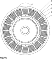
- the IPM electric motor consists of a stator stack (5), manufactured from the laminated sheet metal, which with its form consist of a greater number of teeth, on which excitation windings (4) are made.
- the rotor stack (2) made and/or assembled from the laminated sheet metal, which is placed to the shaft and/or the rotor stack base (1), in which the segments of the assembly make gaps, to which the permanent magnets (3) are put in.
- the rotor stack (2) Due to striving for the controlled magnetic field, the rotor stack (2) contains formed air barriers, which - with their form - influence the course of the lines of magnetic field in the air barrier between the armature and stator stack (2, 5).
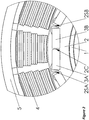
- the subject of this patent application represents an air barrier of a rotor stack (2), in which an individual gap, to which a permanent magnet (3) is installed, contains only one air barrier, which is placed in an individual corner of the rotor stack gap (2), which directly influences the forming of the magnetic field and in this way reduces the effect of the content of higher harmonic component in the induced voltage of the motor and reduced torque oscillation of the motor with interior permanent magnets. It is important to advise that in the preferred embodiment an individual gap of the magnetic field is divided in two parts, which are separated and/or connected by the central connecting element (2C), which essentially contributes to mechanical stability of the rotor stack (2) in higher rotational speed.
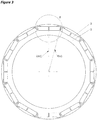
- the electric motor rotor (1), and/or more precisely the rotor stack (2) in the preferred embodiment comprises a bigger number of magnetic field poles, in which the permanent magnets (3) are placed inside the rotor stack (2). Due to the tendency to reach high rotational speeds and as much density of the magnetic field as possible, the rotor stack (2) comprises a higher number of permanent magnets (3), which are evenly arranged by the circumference of the rotor stack (2).
- the rotor stack (2) is divided into internal part, which is put on the shaft and/or rotor holder (1) of the electric motor and the external part, which together with the teeth of the stator stack (5) form an air gap.
- an individual gap of the magnetic pole in the preferred embodiment is divided in two symmetric parts, for which the permanent magnet of an individual pole is divided in two equal parts in the form of a permanent magnet pair (3A, 3B) as shown in figure 2 .
- an individual gap of the rotor stack (2), to which a permanent magnet is installed comprises - in the preferred embodiment - only one air barrier, which is preferentially made in the most outer corner of the gap for installation of the permanent magnet (3A, 3B).
- the permanent magnet (3A, 3B) is in the preferred embodiment in the form of a cuboid, which has - for technological requirements and limitations - in the preferred embodiment the sides and/or the corners rounded by the radius of magnet corner rounding (RM).
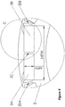
- the segment of the rotor stack (2) comprises a through hole, which in principal presents all key characteristics of the gap for installation of the permanent magnet (3A, 3B), which occurs by placing the segments to the rotor stack (2).
- the rotor stack gap (2), to which the permanent magnets (3A, 3B) are installed is in the preferred embodiment made as a polygon, which in its starting point concurs with the form and dimensions of a permanent magnet (3A, 3B), where the rotor stack gap (2) in the most outer corner of the permanent magnet (3A, 3B) further comprises an air barrier, which has a direct influence on the course and the form of the lines of the magnetic field.
- the air barrier in the basic construction comprises at least three corners and/or contact points (J1, J2, J3), where the first corner (J1) is the starting point of the air barrier in the form of a polygon with at least three corners (J1, J2, J3) where the corners (J2 and J3) present the contact points and/or the intersection with the permanent magnet surface (3A, 3B).
- the position of the starting and/or the contact point (J1) of the polygon of the air barrier is within the area of the circumference of the first point (J1PA), the centre of which is at the very outer corner, in the intersection of the magnet sides (3A, 3B) to be more precise, where the radius of the circumference of the first contact point (J1PA) amounts to half the height of the magnet (3Y).
- the position of other corners of the air barrier polygon (defined by the corners and/or the contact points J1, J2, J3 and J5) is further unidimensionally defined by the intermediate angles of the line segments of the air barrier ( ⁇ , ⁇ , ⁇ ).
- the air barrier comprises a bigger number of corners, which can - instead of the line segments - make a curve in the form of a polygon composed of short segments, which however does not changes the essence of the invention.
- an individual gap for installation of the magnet (3A, 3B) in the preferred embodiment comprises only one air barrier as explained before, in which every magnet pole and/or pair of the permanent magnets (3A, 3B) contains a central connecting element (2C), which connects the internal and outer part of the rotor stack (2).
- the rotor (1) which can comprise a bigger number of rotor stacks and/or segments (S1-2, S2-2), which are aligned around the central axis.
- the rotor (1) comprises two segments (S1-2, S2-2), which are misaligned in respect of the central axis by the misalignment angle of the neighbouring segments of the rotor stack ( ⁇ ), which is in the preferred embodiment between 0.5° and 20°.
- the absolute value of the gap between individual contact points in respect of the starting contact point (J1) in X direction (J2Px, J3Px, J4Px, J5Px) and or the value of the gap between individual contact points regarding the starting point (J1) in Y direction (J2Py, J3Py, J4Py, Jp5Y) is smaller than 3 times the nominal height of the magnet gap (MPH).
- the intermediate angles of the air barrier line segments ( ⁇ , ⁇ , ⁇ ) which are between 30° and 170°.
- the minimal width of the central connecting element (2C-T) and the minimal width of the side connecting element (2S-T) are smaller than 0.2 times the magnet width (3X).
- the angle of the magnet tilt ( ⁇ ) regarding the plane of the central connecting element (RAC) is in the range between 45° and 135°, and is preferably 90°.
- the rounding radii (JR1, JR2 in JR3) and the radius of magnet corner rounding (RM) are smaller than 0.5 times the height of the magnet (3Y).
Landscapes
- Engineering & Computer Science (AREA)
- Power Engineering (AREA)
- Permanent Field Magnets Of Synchronous Machinery (AREA)
- Iron Core Of Rotating Electric Machines (AREA)
Claims (15)
- Rotorstapel (2) eines Elektromotors, der Segmente umfasst, die in der Axialrichtung, von der Rotor-(l)-Rotationsseite aus gesehen, eine Lücke zur Einfügung eines Paars von Permanentmagneten (3A, 3B) von einem Einzel-Magnetpol kreieren,- wobei der entsprechende Permanentmagnet (3A, 3B) in der Form eines Kuboids ist,- wobei eine einzelne Lücke des Magnetpols des Rotorstapels (2) eine Durchgangsbohrung aufweist, die in Bezug auf eine Form und Abmessung zu der Passform des Paares von Permanentmagneten (3A, 3B) passt,- wobei die einzelne Lücke für eine Passung der Permanentmagnete (3A, 3B) weiter zumindest ein zentrales Verbindungselement (2C) und zwei Seitenverbindungselemente (2SA, 2SB) aufweist, die einen inneren und einen äußeren Teil des Rotorstapels (2) mechanisch verbinden,- wobei der innere Teil des Rotorstapels (2) auf eine Welle und/oder einen Rotorhalter (1) gesetzt ist und wobei der äußere Teil des Rotorstapels (2) zusammen mit Zähnen des Statorstapels (5) eine Luftlücke bildet, wobei die Seitenverbindungselemente (2SA, 2SB) eine Luftbarriere in der Form eines Polygons kreieren,- wobei sich die Luftbarriere in der äußersten Ecke des Permanentmagnetenpaares (3A, 3B) entlang zumindest zwei Seiten eines einzelnen Permanentmagneten (3A, 3B) erstreckt,dadurch gekennzeichnet, dass eine minimale Breite (2C-T) des zentralen Verbindungselements (2C) und eine minimale Breite (2S-T) des Seitenverbindungselements (2SA, 2SB) kleiner als 0,2 mal eine Magnetbreite (3X) sind.
- Rotorstapel (2) nach Anspruch 1, dadurch gekennzeichnet, dass
die Luftlücke in der Form des Polygons zumindest drei Kontaktpunkte (J1, J2, J3) umfasst, wobei die Kontaktpunkte (J2 und J3), wieder von der Axial-Rotor-(1)-Richtung, den Schnittpunkt der Luftbarriere in der Form eines Polygons mit der Oberfläche von Permanentmagneten (3A, 3B) darstellen, wobei der Kontaktpunkt (J1) den Startpunkt der Luftbarriere in der Form des Polygons darstellt. - Rotorstapel (2) nach Anspruch 2, dadurch gekennzeichnet, dass
sich der Startkontaktpunkt (J1) innerhalb des Bereichs des Umfangs des ersten Kontaktpunkts (J1PA) befindet, dessen Zentrum sich in der äußersten Ecke des Permanentmagneten (3A, 3B) befindet, wobei der Umfangsradius des ersten Kontaktpunktbereichs (J1PA) kleiner und/oder gleich dem halben Wert der Magnethöhe (3Y) ist. - Rotorstapel (2) nach Anspruch 3, dadurch gekennzeichnet, dass
die Segmente der Luftbarriere in der Form des Polygons mit Ecken und/oder Kontaktpunkten (J1, J2 und J3) mit Bezug auf den Startkontaktpunkt (J1) einen Zwischenwinkel von Linien-Segmenten der Luftbarriere (α) bilden. - Rotorstapel (2) nach Anspruch 4, wobei der Zwischenwinkel in dem Bereich zwischen 30° und 170° ist.
- Rotorstapel (2) nach Anspruch 1, dadurch gekennzeichnet, dass
die Luftbarriere in der Form des Polygons fünf Kontaktpunkte (J1, J2, J3, J4, J5) aufweist, die mit Bezug auf den Startpunkt (J1) durch die Abstände der Kontaktpunkte und/oder Ecken der Luftbarriere in X-Richtung (J2Px, J3Px, J4Px, J5Px) und durch die Abstände der Kontaktpunkte und/oder Ecken der Luftbarriere in Y-Richtung (J2Py, J3Py, J4Py, J5Py) definiert sind, wobei die Luftbarrierensegmente Zwischenwinkel der Linien-Luftbarrierensegmente (α, β, γ) bilden. - Rotorstapel (2) nach Anspruch 6, wobei der Zwischenwinkel innerhalb von 30° und 170° ist.
- Rotorstapel (2) nach Anspruch 6 oder 7, dadurch gekennzeichnet, dass
der Absolutwert der Lücke zwischen den benachbarten Kontaktpunkten (J1, J2, J3, J4, J5) mit Bezug auf den Startkontaktpunkt (J1) in X-Richtung (J2Px, J3Px, J4Px, J5Px) und/oder der Absolutwert der Lücke zwischen einzelnen Kontaktpunkten in Bezug auf den Startkontaktpunkt (J1) in Y-Richtung (J2Py, J3Py, J4Py, J5Py) kleiner als 3 mal die Sollhöhe der Magnetlücke (MPH) ist. - Rotorstapel (2) nach Anspruch 1, dadurch gekennzeichnet, dass
die Permanentmagneten (3A, 3B) in der Lücke des Rotorstapelsegments (2) einen Winkel der Magnetneigung (π) bilden. - Rotorstapel (2) nach Anspruch 9, wobei der Wert des Winkels der Magnetneigung (π) mit Bezug auf die zentrale Verbindungselementebene (RAC) in dem Bereich zwischen 45° und 135° ist.
- Rotorstapel (2) nach Anspruch 9 oder 10, dadurch gekennzeichnet, dass der Magnetneigungswinkel (π) 90° beträgt.
- Rotorstapel (2) nach Anspruch 1, dadurch gekennzeichnet, dass
die Segmente der Luftbarriere in der Form des Polygons sind, mit den Kontaktpunkten (J1, J2, J3, J4 und J5) untereinander durch Rundungsradien (JR1, JR2 und JR3) verbunden, deren Wert kleiner als 0,5 mal die Magnethöhe (3Y) ist. - Rotorstapel (2) nach einem der vorstehenden Ansprüche, dadurch gekennzeichnet, dass
er zumindest zwei Rotorstapelsegmente (S1-2, S2-2) aufweist, die relativ zueinander um einen Versatzwinkel der benachbarten Rotorstapelsegmente (Δ) um die zentrale Achse herum versetzt sind. - Rotorstapel (2) nach Anspruch 13, wobei der Versatzwinkel (Δ) in dem Bereich zwischen 0,5° und 20° ist.
- Rotorstapel (2) nach Anspruch 13 oder 14, dadurch gekennzeichnet, dass der Versatzwinkel der benachbarten Rotorstapelsegmente (Δ) 5° beträgt.
Applications Claiming Priority (2)
| Application Number | Priority Date | Filing Date | Title |
|---|---|---|---|
| SI201400016A SI24435A (sl) | 2014-01-14 | 2014-01-14 | Razdeljena reža rotorskega paketa z vogalnim zračnim žepkom |
| PCT/EP2014/079388 WO2015106946A2 (en) | 2014-01-14 | 2014-12-29 | Split rotor stack gap with a corner air barrier |
Publications (2)
| Publication Number | Publication Date |
|---|---|
| EP3095175A2 EP3095175A2 (de) | 2016-11-23 |
| EP3095175B1 true EP3095175B1 (de) | 2019-02-20 |
Family
ID=52278650
Family Applications (1)
| Application Number | Title | Priority Date | Filing Date |
|---|---|---|---|
| EP14821664.1A Active EP3095175B1 (de) | 2014-01-14 | 2014-12-29 | Geteilte rotorpaketkluft eine eckluftbarriere |
Country Status (5)
| Country | Link |
|---|---|
| US (1) | US9559554B2 (de) |
| EP (1) | EP3095175B1 (de) |
| JP (1) | JP6190544B2 (de) |
| SI (1) | SI24435A (de) |
| WO (1) | WO2015106946A2 (de) |
Cited By (1)
| Publication number | Priority date | Publication date | Assignee | Title |
|---|---|---|---|---|
| DE102019119244A1 (de) * | 2019-07-16 | 2021-01-21 | Dr. Ing. H.C. F. Porsche Aktiengesellschaft | Permanenterregter geschrägter Elektromotor-Rotor |
Families Citing this family (3)
| Publication number | Priority date | Publication date | Assignee | Title |
|---|---|---|---|---|
| WO2017195263A1 (ja) * | 2016-05-10 | 2017-11-16 | 三菱電機株式会社 | 永久磁石型モータ |
| CN106571699A (zh) * | 2016-10-13 | 2017-04-19 | 珠海格力节能环保制冷技术研究中心有限公司 | 驱动电机和电动汽车 |
| US12191722B2 (en) | 2019-05-31 | 2025-01-07 | MagniX USA, Inc. | High-torque electric motor assembly |
Citations (1)
| Publication number | Priority date | Publication date | Assignee | Title |
|---|---|---|---|---|
| WO2013098912A1 (ja) * | 2011-12-26 | 2013-07-04 | 三菱電機株式会社 | 回転子 |
Family Cites Families (11)
| Publication number | Priority date | Publication date | Assignee | Title |
|---|---|---|---|---|
| JP2005354798A (ja) * | 2004-06-10 | 2005-12-22 | Fujitsu General Ltd | 電動機 |
| JP4842670B2 (ja) * | 2006-02-27 | 2011-12-21 | トヨタ自動車株式会社 | ロータおよび電動車両 |
| JP4900069B2 (ja) * | 2007-06-13 | 2012-03-21 | トヨタ自動車株式会社 | 回転電機 |
| TWI405386B (zh) * | 2007-12-28 | 2013-08-11 | Mitsubishi Electric Corp | 旋轉電機 |
| US20100117475A1 (en) * | 2008-11-11 | 2010-05-13 | Ford Global Technologies, Llc | Permanent Magnet Machine with Offset Pole Spacing |
| JP5308832B2 (ja) * | 2009-01-09 | 2013-10-09 | 株式会社日立製作所 | 永久磁石式回転電機 |
| JP2012186889A (ja) * | 2011-03-03 | 2012-09-27 | Nippon Soken Inc | 回転電機 |
| JP5472200B2 (ja) | 2011-05-19 | 2014-04-16 | 株式会社デンソー | 回転電機のロータ |
| JP2013017281A (ja) * | 2011-07-01 | 2013-01-24 | Mitsui High Tec Inc | スキューを有する積層鉄心の製造方法 |
| JP2013162557A (ja) * | 2012-02-01 | 2013-08-19 | Suzuki Motor Corp | 電動回転機 |
| JP5974599B2 (ja) | 2012-04-12 | 2016-08-23 | 株式会社デンソー | 回転電機 |
-
2014
- 2014-01-14 SI SI201400016A patent/SI24435A/sl not_active IP Right Cessation
- 2014-12-29 EP EP14821664.1A patent/EP3095175B1/de active Active
- 2014-12-29 JP JP2016555566A patent/JP6190544B2/ja active Active
- 2014-12-29 US US15/111,481 patent/US9559554B2/en active Active
- 2014-12-29 WO PCT/EP2014/079388 patent/WO2015106946A2/en not_active Ceased
Patent Citations (1)
| Publication number | Priority date | Publication date | Assignee | Title |
|---|---|---|---|---|
| WO2013098912A1 (ja) * | 2011-12-26 | 2013-07-04 | 三菱電機株式会社 | 回転子 |
Cited By (1)
| Publication number | Priority date | Publication date | Assignee | Title |
|---|---|---|---|---|
| DE102019119244A1 (de) * | 2019-07-16 | 2021-01-21 | Dr. Ing. H.C. F. Porsche Aktiengesellschaft | Permanenterregter geschrägter Elektromotor-Rotor |
Also Published As
| Publication number | Publication date |
|---|---|
| SI24435A (sl) | 2015-01-30 |
| US20160336822A1 (en) | 2016-11-17 |
| EP3095175A2 (de) | 2016-11-23 |
| JP6190544B2 (ja) | 2017-08-30 |
| WO2015106946A2 (en) | 2015-07-23 |
| JP2017505602A (ja) | 2017-02-16 |
| US9559554B2 (en) | 2017-01-31 |
| WO2015106946A3 (en) | 2015-11-19 |
Similar Documents
| Publication | Publication Date | Title |
|---|---|---|
| JP5813254B2 (ja) | 永久磁石式回転電機 | |
| US9705366B2 (en) | Embedded permanent magnet rotary electric machine | |
| JP5757281B2 (ja) | 回転電機のロータ | |
| US9531226B2 (en) | Rotor of internal permanent magnet synchronous motor and internal permanent magnet sycnronous motor | |
| US10122231B2 (en) | Rotor and rotary electric machine | |
| EP2458711A2 (de) | Rotor mit eingebettetem Magnet, elektrischer Motor und Herstellungsverfahren für den elektrischen Motor | |
| US20120248915A1 (en) | Permanent magnet embedded rotor for rotating electric machine and rotating electric machine | |
| CN103516081B (zh) | 转子、具有转子的发电-电动机及转子制造方法 | |
| CN109964388B (zh) | 旋转电机用转子以及旋转电机用转子的制造方法 | |
| JP5904293B2 (ja) | 永久磁石埋め込み式回転電機 | |
| EP3095175B1 (de) | Geteilte rotorpaketkluft eine eckluftbarriere | |
| US20130334925A1 (en) | Interior permanent magnet type rotor having continuous skew structure | |
| JP2017123725A (ja) | 回転電動機 | |
| US20150263573A1 (en) | High efficiency internal permanent magnet synchronous electric machine | |
| JP6357859B2 (ja) | 永久磁石埋め込み式回転電機 | |
| JP2019092298A (ja) | ステータ、ステータのブロックおよび回転電機 | |
| JP5193094B2 (ja) | 永久磁石電動機 | |
| CN109997290B (zh) | 同步磁阻型旋转电机 | |
| JP2014087229A (ja) | 磁石埋込型ロータ | |
| JP6503016B2 (ja) | ロータおよび回転電機 | |
| JP2014113033A (ja) | 磁石埋込式回転電機 | |
| KR102093242B1 (ko) | 회전자 및 회전 전기 장치 | |
| WO2022176829A1 (ja) | ロータ | |
| EP4329152A1 (de) | Rotor | |
| JP6853335B2 (ja) | ステータおよび回転電機 |
Legal Events
| Date | Code | Title | Description |
|---|---|---|---|
| PUAI | Public reference made under article 153(3) epc to a published international application that has entered the european phase |
Free format text: ORIGINAL CODE: 0009012 |
|
| 17P | Request for examination filed |
Effective date: 20160701 |
|
| AK | Designated contracting states |
Kind code of ref document: A2 Designated state(s): AL AT BE BG CH CY CZ DE DK EE ES FI FR GB GR HR HU IE IS IT LI LT LU LV MC MK MT NL NO PL PT RO RS SE SI SK SM TR |
|
| AX | Request for extension of the european patent |
Extension state: BA ME |
|
| DAX | Request for extension of the european patent (deleted) | ||
| REG | Reference to a national code |
Ref country code: DE Ref legal event code: R079 Ref document number: 602014041433 Country of ref document: DE Free format text: PREVIOUS MAIN CLASS: H02K0001270000 Ipc: H02K0021140000 |
|
| RIC1 | Information provided on ipc code assigned before grant |
Ipc: H02K 21/14 20060101AFI20170706BHEP Ipc: H02K 1/27 20060101ALI20170706BHEP |
|
| GRAP | Despatch of communication of intention to grant a patent |
Free format text: ORIGINAL CODE: EPIDOSNIGR1 |
|
| STAA | Information on the status of an ep patent application or granted ep patent |
Free format text: STATUS: GRANT OF PATENT IS INTENDED |
|
| INTG | Intention to grant announced |
Effective date: 20170922 |
|
| GRAJ | Information related to disapproval of communication of intention to grant by the applicant or resumption of examination proceedings by the epo deleted |
Free format text: ORIGINAL CODE: EPIDOSDIGR1 |
|
| STAA | Information on the status of an ep patent application or granted ep patent |
Free format text: STATUS: REQUEST FOR EXAMINATION WAS MADE |
|
| INTC | Intention to grant announced (deleted) | ||
| STAA | Information on the status of an ep patent application or granted ep patent |
Free format text: STATUS: EXAMINATION IS IN PROGRESS |
|
| 17Q | First examination report despatched |
Effective date: 20180221 |
|
| GRAS | Grant fee paid |
Free format text: ORIGINAL CODE: EPIDOSNIGR3 |
|
| STAA | Information on the status of an ep patent application or granted ep patent |
Free format text: STATUS: GRANT OF PATENT IS INTENDED |
|
| GRAP | Despatch of communication of intention to grant a patent |
Free format text: ORIGINAL CODE: EPIDOSNIGR1 |
|
| INTG | Intention to grant announced |
Effective date: 20180809 |
|
| GRAA | (expected) grant |
Free format text: ORIGINAL CODE: 0009210 |
|
| STAA | Information on the status of an ep patent application or granted ep patent |
Free format text: STATUS: THE PATENT HAS BEEN GRANTED |
|
| AK | Designated contracting states |
Kind code of ref document: B1 Designated state(s): AL AT BE BG CH CY CZ DE DK EE ES FI FR GB GR HR HU IE IS IT LI LT LU LV MC MK MT NL NO PL PT RO RS SE SI SK SM TR |
|
| REG | Reference to a national code |
Ref country code: GB Ref legal event code: FG4D |
|
| REG | Reference to a national code |
Ref country code: CH Ref legal event code: EP |
|
| REG | Reference to a national code |
Ref country code: AT Ref legal event code: REF Ref document number: 1099474 Country of ref document: AT Kind code of ref document: T Effective date: 20190315 |
|
| REG | Reference to a national code |
Ref country code: IE Ref legal event code: FG4D |
|
| REG | Reference to a national code |
Ref country code: DE Ref legal event code: R096 Ref document number: 602014041433 Country of ref document: DE |
|
| REG | Reference to a national code |
Ref country code: NL Ref legal event code: MP Effective date: 20190220 |
|
| REG | Reference to a national code |
Ref country code: LT Ref legal event code: MG4D |
|
| PG25 | Lapsed in a contracting state [announced via postgrant information from national office to epo] |
Ref country code: LT Free format text: LAPSE BECAUSE OF FAILURE TO SUBMIT A TRANSLATION OF THE DESCRIPTION OR TO PAY THE FEE WITHIN THE PRESCRIBED TIME-LIMIT Effective date: 20190220 Ref country code: PT Free format text: LAPSE BECAUSE OF FAILURE TO SUBMIT A TRANSLATION OF THE DESCRIPTION OR TO PAY THE FEE WITHIN THE PRESCRIBED TIME-LIMIT Effective date: 20190620 Ref country code: NO Free format text: LAPSE BECAUSE OF FAILURE TO SUBMIT A TRANSLATION OF THE DESCRIPTION OR TO PAY THE FEE WITHIN THE PRESCRIBED TIME-LIMIT Effective date: 20190520 Ref country code: FI Free format text: LAPSE BECAUSE OF FAILURE TO SUBMIT A TRANSLATION OF THE DESCRIPTION OR TO PAY THE FEE WITHIN THE PRESCRIBED TIME-LIMIT Effective date: 20190220 Ref country code: SE Free format text: LAPSE BECAUSE OF FAILURE TO SUBMIT A TRANSLATION OF THE DESCRIPTION OR TO PAY THE FEE WITHIN THE PRESCRIBED TIME-LIMIT Effective date: 20190220 Ref country code: NL Free format text: LAPSE BECAUSE OF FAILURE TO SUBMIT A TRANSLATION OF THE DESCRIPTION OR TO PAY THE FEE WITHIN THE PRESCRIBED TIME-LIMIT Effective date: 20190220 |
|
| PG25 | Lapsed in a contracting state [announced via postgrant information from national office to epo] |
Ref country code: RS Free format text: LAPSE BECAUSE OF FAILURE TO SUBMIT A TRANSLATION OF THE DESCRIPTION OR TO PAY THE FEE WITHIN THE PRESCRIBED TIME-LIMIT Effective date: 20190220 Ref country code: GR Free format text: LAPSE BECAUSE OF FAILURE TO SUBMIT A TRANSLATION OF THE DESCRIPTION OR TO PAY THE FEE WITHIN THE PRESCRIBED TIME-LIMIT Effective date: 20190521 Ref country code: HR Free format text: LAPSE BECAUSE OF FAILURE TO SUBMIT A TRANSLATION OF THE DESCRIPTION OR TO PAY THE FEE WITHIN THE PRESCRIBED TIME-LIMIT Effective date: 20190220 Ref country code: LV Free format text: LAPSE BECAUSE OF FAILURE TO SUBMIT A TRANSLATION OF THE DESCRIPTION OR TO PAY THE FEE WITHIN THE PRESCRIBED TIME-LIMIT Effective date: 20190220 Ref country code: BG Free format text: LAPSE BECAUSE OF FAILURE TO SUBMIT A TRANSLATION OF THE DESCRIPTION OR TO PAY THE FEE WITHIN THE PRESCRIBED TIME-LIMIT Effective date: 20190520 Ref country code: IS Free format text: LAPSE BECAUSE OF FAILURE TO SUBMIT A TRANSLATION OF THE DESCRIPTION OR TO PAY THE FEE WITHIN THE PRESCRIBED TIME-LIMIT Effective date: 20190620 |
|
| REG | Reference to a national code |
Ref country code: AT Ref legal event code: MK05 Ref document number: 1099474 Country of ref document: AT Kind code of ref document: T Effective date: 20190220 |
|
| PG25 | Lapsed in a contracting state [announced via postgrant information from national office to epo] |
Ref country code: AL Free format text: LAPSE BECAUSE OF FAILURE TO SUBMIT A TRANSLATION OF THE DESCRIPTION OR TO PAY THE FEE WITHIN THE PRESCRIBED TIME-LIMIT Effective date: 20190220 Ref country code: ES Free format text: LAPSE BECAUSE OF FAILURE TO SUBMIT A TRANSLATION OF THE DESCRIPTION OR TO PAY THE FEE WITHIN THE PRESCRIBED TIME-LIMIT Effective date: 20190220 Ref country code: CZ Free format text: LAPSE BECAUSE OF FAILURE TO SUBMIT A TRANSLATION OF THE DESCRIPTION OR TO PAY THE FEE WITHIN THE PRESCRIBED TIME-LIMIT Effective date: 20190220 Ref country code: IT Free format text: LAPSE BECAUSE OF FAILURE TO SUBMIT A TRANSLATION OF THE DESCRIPTION OR TO PAY THE FEE WITHIN THE PRESCRIBED TIME-LIMIT Effective date: 20190220 Ref country code: RO Free format text: LAPSE BECAUSE OF FAILURE TO SUBMIT A TRANSLATION OF THE DESCRIPTION OR TO PAY THE FEE WITHIN THE PRESCRIBED TIME-LIMIT Effective date: 20190220 Ref country code: DK Free format text: LAPSE BECAUSE OF FAILURE TO SUBMIT A TRANSLATION OF THE DESCRIPTION OR TO PAY THE FEE WITHIN THE PRESCRIBED TIME-LIMIT Effective date: 20190220 Ref country code: EE Free format text: LAPSE BECAUSE OF FAILURE TO SUBMIT A TRANSLATION OF THE DESCRIPTION OR TO PAY THE FEE WITHIN THE PRESCRIBED TIME-LIMIT Effective date: 20190220 Ref country code: SK Free format text: LAPSE BECAUSE OF FAILURE TO SUBMIT A TRANSLATION OF THE DESCRIPTION OR TO PAY THE FEE WITHIN THE PRESCRIBED TIME-LIMIT Effective date: 20190220 |
|
| REG | Reference to a national code |
Ref country code: DE Ref legal event code: R097 Ref document number: 602014041433 Country of ref document: DE |
|
| PG25 | Lapsed in a contracting state [announced via postgrant information from national office to epo] |
Ref country code: PL Free format text: LAPSE BECAUSE OF FAILURE TO SUBMIT A TRANSLATION OF THE DESCRIPTION OR TO PAY THE FEE WITHIN THE PRESCRIBED TIME-LIMIT Effective date: 20190220 Ref country code: SM Free format text: LAPSE BECAUSE OF FAILURE TO SUBMIT A TRANSLATION OF THE DESCRIPTION OR TO PAY THE FEE WITHIN THE PRESCRIBED TIME-LIMIT Effective date: 20190220 |
|
| PLBE | No opposition filed within time limit |
Free format text: ORIGINAL CODE: 0009261 |
|
| STAA | Information on the status of an ep patent application or granted ep patent |
Free format text: STATUS: NO OPPOSITION FILED WITHIN TIME LIMIT |
|
| PG25 | Lapsed in a contracting state [announced via postgrant information from national office to epo] |
Ref country code: AT Free format text: LAPSE BECAUSE OF FAILURE TO SUBMIT A TRANSLATION OF THE DESCRIPTION OR TO PAY THE FEE WITHIN THE PRESCRIBED TIME-LIMIT Effective date: 20190220 |
|
| 26N | No opposition filed |
Effective date: 20191121 |
|
| PG25 | Lapsed in a contracting state [announced via postgrant information from national office to epo] |
Ref country code: SI Free format text: LAPSE BECAUSE OF FAILURE TO SUBMIT A TRANSLATION OF THE DESCRIPTION OR TO PAY THE FEE WITHIN THE PRESCRIBED TIME-LIMIT Effective date: 20190220 |
|
| PGFP | Annual fee paid to national office [announced via postgrant information from national office to epo] |
Ref country code: FR Payment date: 20191226 Year of fee payment: 6 |
|
| PG25 | Lapsed in a contracting state [announced via postgrant information from national office to epo] |
Ref country code: TR Free format text: LAPSE BECAUSE OF FAILURE TO SUBMIT A TRANSLATION OF THE DESCRIPTION OR TO PAY THE FEE WITHIN THE PRESCRIBED TIME-LIMIT Effective date: 20190220 |
|
| REG | Reference to a national code |
Ref country code: CH Ref legal event code: PL |
|
| REG | Reference to a national code |
Ref country code: BE Ref legal event code: MM Effective date: 20191231 |
|
| PG25 | Lapsed in a contracting state [announced via postgrant information from national office to epo] |
Ref country code: MC Free format text: LAPSE BECAUSE OF FAILURE TO SUBMIT A TRANSLATION OF THE DESCRIPTION OR TO PAY THE FEE WITHIN THE PRESCRIBED TIME-LIMIT Effective date: 20190220 |
|
| GBPC | Gb: european patent ceased through non-payment of renewal fee |
Effective date: 20191229 |
|
| PG25 | Lapsed in a contracting state [announced via postgrant information from national office to epo] |
Ref country code: GB Free format text: LAPSE BECAUSE OF NON-PAYMENT OF DUE FEES Effective date: 20191229 Ref country code: LU Free format text: LAPSE BECAUSE OF NON-PAYMENT OF DUE FEES Effective date: 20191229 Ref country code: IE Free format text: LAPSE BECAUSE OF NON-PAYMENT OF DUE FEES Effective date: 20191229 |
|
| PG25 | Lapsed in a contracting state [announced via postgrant information from national office to epo] |
Ref country code: CH Free format text: LAPSE BECAUSE OF NON-PAYMENT OF DUE FEES Effective date: 20191231 Ref country code: LI Free format text: LAPSE BECAUSE OF NON-PAYMENT OF DUE FEES Effective date: 20191231 Ref country code: BE Free format text: LAPSE BECAUSE OF NON-PAYMENT OF DUE FEES Effective date: 20191231 |
|
| PG25 | Lapsed in a contracting state [announced via postgrant information from national office to epo] |
Ref country code: CY Free format text: LAPSE BECAUSE OF FAILURE TO SUBMIT A TRANSLATION OF THE DESCRIPTION OR TO PAY THE FEE WITHIN THE PRESCRIBED TIME-LIMIT Effective date: 20190220 |
|
| PG25 | Lapsed in a contracting state [announced via postgrant information from national office to epo] |
Ref country code: MT Free format text: LAPSE BECAUSE OF FAILURE TO SUBMIT A TRANSLATION OF THE DESCRIPTION OR TO PAY THE FEE WITHIN THE PRESCRIBED TIME-LIMIT Effective date: 20190220 Ref country code: HU Free format text: LAPSE BECAUSE OF FAILURE TO SUBMIT A TRANSLATION OF THE DESCRIPTION OR TO PAY THE FEE WITHIN THE PRESCRIBED TIME-LIMIT; INVALID AB INITIO Effective date: 20141229 |
|
| PG25 | Lapsed in a contracting state [announced via postgrant information from national office to epo] |
Ref country code: FR Free format text: LAPSE BECAUSE OF NON-PAYMENT OF DUE FEES Effective date: 20201231 |
|
| PG25 | Lapsed in a contracting state [announced via postgrant information from national office to epo] |
Ref country code: MK Free format text: LAPSE BECAUSE OF FAILURE TO SUBMIT A TRANSLATION OF THE DESCRIPTION OR TO PAY THE FEE WITHIN THE PRESCRIBED TIME-LIMIT Effective date: 20190220 |
|
| PGFP | Annual fee paid to national office [announced via postgrant information from national office to epo] |
Ref country code: DE Payment date: 20251211 Year of fee payment: 12 |