EP3095352A1 - Befestigungsanordnung zum verbinden eines bauteiles - Google Patents
Befestigungsanordnung zum verbinden eines bauteiles Download PDFInfo
- Publication number
- EP3095352A1 EP3095352A1 EP16160072.1A EP16160072A EP3095352A1 EP 3095352 A1 EP3095352 A1 EP 3095352A1 EP 16160072 A EP16160072 A EP 16160072A EP 3095352 A1 EP3095352 A1 EP 3095352A1
- Authority
- EP
- European Patent Office
- Prior art keywords
- fastening
- furniture
- opening
- fastening arrangement
- arrangement
- Prior art date
- Legal status (The legal status is an assumption and is not a legal conclusion. Google has not performed a legal analysis and makes no representation as to the accuracy of the status listed.)
- Granted
Links
Images


Classifications
-
- A—HUMAN NECESSITIES
- A47—FURNITURE; DOMESTIC ARTICLES OR APPLIANCES; COFFEE MILLS; SPICE MILLS; SUCTION CLEANERS IN GENERAL
- A47B—TABLES; DESKS; OFFICE FURNITURE; CABINETS; DRAWERS; GENERAL DETAILS OF FURNITURE
- A47B95/00—Fittings for furniture
-
- A—HUMAN NECESSITIES
- A47—FURNITURE; DOMESTIC ARTICLES OR APPLIANCES; COFFEE MILLS; SPICE MILLS; SUCTION CLEANERS IN GENERAL
- A47B—TABLES; DESKS; OFFICE FURNITURE; CABINETS; DRAWERS; GENERAL DETAILS OF FURNITURE
- A47B88/00—Drawers for tables, cabinets or like furniture; Guides for drawers
- A47B88/40—Sliding drawers; Slides or guides therefor
- A47B88/423—Fastening devices for slides or guides
- A47B88/43—Fastening devices for slides or guides at cabinet side
-
- E—FIXED CONSTRUCTIONS
- E06—DOORS, WINDOWS, SHUTTERS, OR ROLLER BLINDS IN GENERAL; LADDERS
- E06B—FIXED OR MOVABLE CLOSURES FOR OPENINGS IN BUILDINGS, VEHICLES, FENCES OR LIKE ENCLOSURES IN GENERAL, e.g. DOORS, WINDOWS, BLINDS, GATES
- E06B9/00—Screening or protective devices for wall or similar openings, with or without operating or securing mechanisms; Closures of similar construction
- E06B9/02—Shutters, movable grilles, or other safety closing devices, e.g. against burglary
- E06B9/08—Roll-type closures
- E06B9/11—Roller shutters
- E06B9/115—Roller shutters specially adapted for furniture
Definitions
- the invention relates to a fastening arrangement with the features of the preamble of claim 1 and a cupboard furniture.
- the DE 29907856 U1 a guide device for receiving sliding and sliding elements, such as blinds, shutters or sliding doors, in at least one U-rail slideway furniture with a fixable to the furniture body base profile as a mounting arrangement and a connectable with this cover to cover the attachment of the base profile to the furniture body, in which case the slide track is formed in a separate rail element which is detachably inserted into a recess of the base profile.
- sliding and sliding elements such as blinds, shutters or sliding doors
- the base profile is fixed by known fasteners such as screws on the inside of the furniture body and serves as a mounting arrangement for a subsequently insertable rail element which is fixable attachable in the base profile.
- the disclosure DE 10 2004 005 781 A1 a Venetian blind unit for retrofitting or equipping a furniture provided with an opening to be closed, with a blind module which can be moved into the furniture and a blind which can be moved from an open position to an at least partially closed position, as well as blind guides arranged on two sides of the opening, wherein the blind guides are each one Receiving profile and have a releasably fixed on the receiving profile cover profile, wherein the receiving profiles have a projecting into the opening of the furniture guide body for installation of the blind and a shutter guide in the region of a receiving profile has a cover profile at least partially coverable passage area for the introduction of the blind in the blind guide ,
- the recording profiles are known per se fixing fixed in the front of the furniture body. This acting as a fastening assembly base profile is then connected to a shutter guide having an approximately U-shaped groove for the shutter to be moved.
- a disadvantage of the prior art is that the mounting arrangements are very expensive to produce and extremely time consuming to install.
- Another disadvantage of the mounting arrangements of the known prior art is that the complex installation of the mounting arrangements and the various guide systems on the cabinet body tools such as drills, screwdrivers and the like and accessory components such as screws requires and a fairly high amount of time and craftsmanship.
- it is necessary for the mounting of the mounting arrangements of the prior art that sufficient experience in the assembly of furniture or blind systems is necessary or even necessary. In the case of the fastening arrangements of the prior art, this entails the risk of incorrect assembly, incorrect handling of components and considerable additional expenditure.
- this object is achieved by the features of claim 1.
- the object is further achieved by a cabinet with the features of claim 15. Further advantageous embodiments are described in the subclaims.
- a fastening arrangement for connecting a component, in particular at least one guide device to at least one furniture body, comprising at least one base is characterized in that the base has at least one, of her wegragend arranged fixing device, and at least one fastening device wherein the fastening device comprises at least one, at least having an opening, fastening receptacle.
- This advantageous embodiment of the fastening arrangement according to the invention makes it possible for the first time to mount guide systems on cabinet furniture without using additional tools or accessory components.
- all types of cabinet furniture can be provided with a need-based guide device and equipped with a correspondingly sized closure assembly. This can be advantageously realized so that the fastening arrangement according to the invention in the already existing in the furniture carcass holes or drill rows can be mounted in the otherwise normal use of the cabinet furniture, for example, shelves and the like can be attached.
- the fastening receptacle of the fastening device is arranged at the base of the fastening arrangement.
- fastening receptacle of the fastening device is arranged at a distance from the base of the fastening arrangement via a spacer element.
- the fastening receptacle of the fastening device is arranged approximately orthogonal to the base of the fastening arrangement.
- the fastening arrangement according to the invention can be mounted and fixed in all currently known hairpin.
- the fastening arrangement according to the invention is further characterized in that the fixing device has at least one fixing element.
- This fixing element is advantageously designed so that it can receive the guide devices positively and / or positively locking.
- the fastening arrangement according to the invention is designed so that the fixing device has at least two, oppositely arranged, fixing elements. As a result, the fixation of the guide devices is possible very quickly and without tools.
- the fastening arrangement according to the invention can also be designed so that the fixing device has at least two, mutually offset, fixing elements.
- the fastening arrangement according to the invention so differently sized guide device can be securely fixed.
- a first fixing device is arranged at a distance from the base of a second fixing device.
- At least one third fixing device is arranged approximately orthogonally on at least one fixing device.
- the fastening arrangement according to the invention can thus be positioned or fixed in a multifunctional manner on the furniture carcass and there are also approximately orthogonally arranged guide devices and other receiving elements on the respective furniture carcass fixable without tools.
- the third fixing device is arranged at a distance from at least one connecting element to the first or second fixing device.
- At least one centering element is arranged on at least one fixing device. This centering element helps the fastening arrangement according to the invention to an exact positioning of the guide devices to be fixed to the fastening arrangement according to the invention and to a simple and with little effort associated, assembly.
- Another advantage of the fastening arrangement according to the invention is that at least one retaining element is arranged on at least one fixing device. This holding element of the fastening arrangement according to the invention serves to additionally position the fixed guide devices.
- the fastening arrangement according to the invention is advantageously designed so that at least one fixing element arranged at a distance from a connecting element is arranged on at least one fixing device. This also leads to a better positioning of the guide devices to be fixed of the fastening arrangement according to the invention.
- the fastening arrangement according to the invention is furthermore designed such that the retaining element has at least one plate element arranged approximately orthogonally to the fixing device and / or to the connecting element. In this way, a secure and above all visually appealing fixation and completion of the guide devices on the furniture body can be realized.
- the fastening arrangement according to the invention is furthermore designed such that the fastening receptacle of the fastening device has at least two openings spaced apart from one another over a length L.
- the length L of the spaced-apart openings is dimensioned so that it corresponds to the usual in cabinet furniture rows of holes or drill rows, which are already available for the attachment of, for example, shelves and the like.
- the fastening arrangement according to the invention can be fixed simply, safely and without tools via fastening elements known per se via the openings of the fastening receptacle on the furniture carcass.
- the invention further relates to a cabinet furniture with a furniture body, comprising at least one, having an opening, side wall and / or bottom and / or topsoil with at least one shutter assembly such as blind, roller shutter mat and The like, which are arranged in the region of an opening of the furniture body from a closed position (GP) to an open position (OP) and back, with at least one arranged on the furniture body guide device and at least one mounting arrangement according to the previous versions.
- GP closed position
- OP open position
- the cabinet furniture according to the invention is further characterized in that the fastening device has at least one, in the opening of the furniture body protruding, at least one side wall and / or bottom and / or top floor supporting, at least one opening having, mounting receptacle.
- the fastening arrangement is fixed to at least one side wall and / or bottom and / or top floor via at least one fastening element, which is arranged in the opening of the fastening receptacle.
- the fastening element connects the opening of the fastening receptacle of the fastening device with the opening of the side wall and / or the bottom and / or the upper floor fixing.
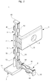
- FIG. 1 is a perspective view of a fastening arrangement 1 according to the invention shown.
- the fastening arrangement 1 has a base 2 and a first fixing device 4 protruding therefrom, and a second fixing device 5 arranged at a distance from the base 2 of the first fixing device 4.
- the fastening device 3 is arranged via a spacer element 31.
- the spacer element 31 and the fastening device 3 are materially connected in this embodiment by known per se bonding or welding with the base 2 of the mounting assembly 1.
- the fastening receptacle 32 of the fastening device 3 is arranged approximately orthogonal to the base 2 of the fastening arrangement 1.
- the fastening device 3 is formed in this embodiment so that it has a, with two spaced-apart openings 8, mounting receptacle 32.
- the openings 8 of the mounting receptacle 32 are spaced apart in this embodiment over a distance L, wherein the distance L corresponds to the distance of the openings or holes in the walls of a furniture carcass.
- the fastening arrangement 1 is furthermore designed such that the fixing device 4, 5 has at least one fixing element 41, 42, 51, 52.
- the fixing elements 41, 42 of the first fixing device 4 and the fixing elements 51, 52 of the second fixing device 5 are arranged offset to one another and materially connected.
- the fastening arrangement 1 is furthermore designed such that at least one centering element 43, 53 is arranged on the free end of the fixing device 4, 5 opposite the base 2.
- the fastening assembly 1 When used according to the invention the fastening assembly 1 according to the invention for connecting a component, in particular at least one guide device not shown on at least one furniture body, not shown, the guide device is arranged parallel to the mounting assembly 1 and positioned on the centering elements 43, 53. In a further operation, the parallel, spaced apart from the mounting arrangement 1 guide device is then pressed onto the mounting assembly 1, so that the fixing elements 41, 42 of the first fixing device 4 and the fixing elements 51, 52 of the second fixing device 5 engage behind the guide device, not shown latching and fix , The fastening arrangement 1 is furthermore designed so that the width of the base 2 is smaller than the thickness of the walls of the furniture body, not shown.
- the fastening arrangement 1 is likewise designed such that the fastening receptacle 32 of the fastening device 3 is arranged approximately orthogonal to the spacer element 31.
- the fastening arrangement 1 can also be designed such that the fastening receptacle 32 is connected to the spacer element 31 and the base 2 in a force-locking or form-fitting manner via fastening elements known per se, for example screws, nails, dowels and the like.
- FIG. 2 a perspective view of a further fastening arrangement 1 according to the invention is shown.
- the fastening arrangement 1 has a base 2 and in each case one of them protruding first fixing device 4 and a second fixing device. 5
- the fastening arrangement 1 is furthermore designed such that it has a fastening device 3, wherein the fastening device 3 has at least one fastening receptacle 32 having at least one opening 8.
- the fastening receptacle 32 of the fastening device 3 is arranged in this embodiment on the base 2 of the fastening arrangement 1. Furthermore, the fastening receptacle 32 of the fastening device 3 is arranged approximately orthogonal to the base 2 of the fastening device 1.
- the fastening arrangement 1 is designed such that the first fixing device 4 has at least one fixing element 41, 42 and the second fixing device 5 has at least one fixing element 51, 52.
- the fixing elements 41, 42 are arranged opposite one another and are connected in a material-locking or one-piece manner.
- the fixing elements 51, 52 are likewise arranged opposite one another and are connected in a material-locking or one-piece manner.
- the fixing elements 41, 42, 51, 52 are designed as arranged at an acute angle latch hooks.
- the fastening arrangement 1 is furthermore designed in such a way that at least one third fixing device 6 is arranged approximately orthogonally on at least one fixing device 4, 5.
- the third fixing device 6 is arranged at a distance from the second fixing device 5 via a connecting element 64, 72.
- the fastening arrangement 1 according to the invention can thus be arranged in the intended use for connecting a component, in particular at least one guide rail to at least one furniture carcass directly in the corner of two walls of the furniture carcass and the corresponding guide devices are mounted.
- the fastening arrangement 1 has, on the first fixing device 4, a centering element 43 arranged opposite the base 2.
- the fastening arrangement 1 according to the invention is furthermore designed such that the connecting element 72 arranged on the second fixing device 5 has a width which corresponds approximately to the width of the centering element 43 of the first fixing device 4.
- This connecting element 72 thus also has a centering function.
- the mounting arrangement 1 is formed in this embodiment so that spaced over the connecting element 72 to the second fixing device 5, a spaced-apart retaining element 7 is arranged.
- the holding element 7 has at least one plate element 71 arranged approximately orthogonally to the second fixing device 5 and to the connecting element 72.
- the plate member 71 of the mounting assembly 1 according to the invention is dimensioned in this embodiment that a, not shown, guide device to the mounting assembly 1 can be fixed and placed on the plate member 71 of the holding member 7, also a, not shown, receiving element can be placed.
- the fastening arrangement 1 according to the invention has a third fixing device 6, which in turn has two fixing elements 61, 62 arranged opposite one another.
- the third fixing device 6 is formed in this embodiment, that at its, the connecting element 64 opposite free end, arranged centering element 63 has.
- the illustrated guide devices as well as other profile elements can thus be arranged and fixed in the intended use of the fastening arrangement 1 according to the invention.
- the fastening arrangement 1 according to the invention is also designed such that, when used as intended on a wall of a furniture body, not shown, the third fastening device 6 can be separated via the connecting element 64 from the fastening arrangement 1, so that increased flexibility in use of the fastening arrangement according to the invention can be realized.
- the fastening assembly 1 is made in this embodiment of a polymeric material selected from the group of polyamides, polycarbonates, polyolefins, polyoxymethylenes, polyvinyl chlorides and the like and economically and inexpensively manufactured in the known injection molding.
- the fastening arrangement 1 according to the invention is made of metallic, ceramic, duromer or lignocellulosic materials. Furthermore, it is possible in the mounting arrangement 1 according to the invention to provide these in different colors or widths available, so that when used as intended, the fastening assembly 1 for connecting a component, in particular at least one guide device to at least one furniture body this both the geometry and the Design and the color scheme of the furniture body are customizable.
- FIG. 3 is a perspective view of a cabinet furniture 10 is shown.
- the cabinet furniture 10 is formed in this embodiment, that it has a furniture body 100 and a closure assembly module 110.
- the furniture body 100 of the cabinet furniture 10 has in this embodiment side walls 11, 12, a bottom 13, a top floor 14 and a rear wall 15.
- a closure assembly 25 is arranged, which is formed in this embodiment as a planar blind.
- the closure assembly is arranged from a closed position GP to an open position OP and movable back, wherein in this embodiment, the closure assembly 25 is shown in an open position OP.
- guiding devices 30, which are fixed with the aid of a fastening arrangement 1, are shown on the furniture body 100, in each case on the narrow sides of the side wall 11, 12.
- each case two fastening arrangements 1 are respectively arranged on the side wall 11 and on the side wall 12.
- the fastening arrangement 1 is formed in this embodiment so that it has at least one fastening device 3, wherein the fastening device 3 has at least one, at least one opening having fastening receptacle 32.
- the cabinet furniture 10 is formed so that the guide device 30 is fixed to the side wall 12 via the mounting assembly 1 and the guide device 30 is still positioned on the shutter assembly module 110 at the same time.
- a fastening arrangement 1 can be seen at the lower free end of the side wall 12 and on the front side of the bottom 13 of the furniture body 100.
- a fastening arrangement 1 can be seen at the lower free end of the side wall 12 and on the front side of the bottom 13 of the furniture body 100.
- a third fixing device 6 is arranged approximately orthogonally to the non-visible fixing device 4, 5.
- the third fixing device 6, which is arranged in this embodiment on the front side of the bottom 13 of the furniture body 100, can receive or fix a mounting element 19 to be mounted on the furniture body 100.
- the guide device 30 and the orthogonal thereto arranged receiving element 19 only partially shown in section.
- the arranged here mounting arrangement 1 is formed in detail as in the Fig. 1 or 2 described.
- the cabinet furniture 10 is formed so that it has various openings 40.
- the openings 40 of the side wall 11, which are also arranged on the non-visible side of the side wall 12, are in each case arranged side by side or one above the other at a defined distance. These are also referred to as rows of holes and have a well-defined distance from each other.
- the fastening arrangement 1 is fixed to at least one side wall 11, 12 in this exemplary embodiment via a fastening element 9, which is arranged in the opening 8, not illustrated, of the fastening receptacle 32.
- a fastening element 9 which is arranged in the opening 8, not illustrated, of the fastening receptacle 32.
- the not visible in this embodiment opening 8 of the fastening receptacle 32 of the fastening device 3 is located exactly opposite the opening 40 of the side wall 11, 12.
- the fastening element 9 is in this embodiment, for example, a screw or a dowel, which the not shown opening 8 of the fastening receptacle 32nd the fastening device 3 with the opening 40 of the side wall 11, 12 connects fixing.
- the correspondingly dimensioned guide device 30 is in each case arranged parallel to the mounting arrangements 1, positioned by the centering elements 43, 53 arranged in the mounting arrangement 1 and subsequently by latching engagement of the fixing elements 41, 42, 51, 52 of the fixing devices 4, 5 on at least one Fixed end of the furniture body 100.
- the cabinet furniture 10 is further designed so that on the front side of the bottom 13 of the furniture body 100, an additional receiving element 19 is attached.
- the receiving element 19 is formed in this embodiment so that it can be arranged and fixed via the fixing elements 61, 62 of the third fixing device 6 respectively at the free ends of the guide device 30.
- the cabinet furniture 10 is further formed in this embodiment, that on the bottom 14 of the furniture body 100, the closure assembly module 110 is arranged.
- the closure assembly module 110 further has on its side adjacent to the closure element 25 a cover element 17 which positively influences the optics of the cabinet furniture 10.
- the cabinet furniture 10 is further designed so that the fastening device 3 of the fastening arrangement 1 at least one, in the opening 20 of the furniture body 100 projecting, on the side wall 11, 12 supporting, at least one opening 8 having, fastening receptacle 32 has.
- the assembly of the closure assembly module 110 on the furniture body 100 designed in this embodiment as extremely simple, fast and inexpensive.
- the finished furniture body 100 receives on its, not visible, topsoil 14, a closure assembly module 110, which is positioned or fixed by a non-positive and / or positive connection.
- the fastening arrangements 1 are now positioned on the respective end faces of the side wall 11, 12 or fixed via the fastening element 9.
- the respective dimensioned guide device 30 is arranged on the mounting arrangements 1 and fixed on the fixing elements of the fixing devices not visible here.
- the closure arrangement 25 can now be moved out of the closure arrangement module 110 into the guide devices 30 via the grip element 18 arranged at its free end so that the closure arrangement 25 in the region of the opening 20 of the furniture body 100 moves from an open position OP to a closed position GP and is arranged back movable.
- an additional receiving element 19 can be arranged on the end face of the bottom 13 of the furniture body 100 via the third fixing device 6, which in turn closes in the closed position GP with the underside of the grip element 18 of the closure assembly 25.
- the cabinet furniture 10 has a furniture body 100, comprising at least one, an opening 40 having bottom 13 and upper floor 14 and a side wall 11, 12 and an intermediate wall 16 and the rear wall 15.
- the cabinet furniture 10 further comprises a closure assembly 25 which is formed as a blind and is arranged in the region of the opening 20 of the furniture body 100 from a closed position GP in an open position OP and back.
- a closure assembly 25 which is formed as a blind and is arranged in the region of the opening 20 of the furniture body 100 from a closed position GP in an open position OP and back.
- guide devices 30 are arranged in this embodiment at the end faces of the bottom 13 and the topsoil 14, which are fixed with at least one mounting assembly 1.
- the fastening arrangement 1 has a fastening device 3, which has at least one, in the opening 20 of the furniture body 100 projecting, at the bottom 13 and upper floor 14 supporting, at least one non-visible opening 8 having, mounting receptacle 32.
- the mounting arrangement 1 is fixed in this embodiment, in each case via a fastening element 9 in the bottom 13 or in the upper bottom 14 of the furniture body 100.
- the bottom 13 of the furniture body 100 is formed so that it has various openings 40 which are arranged equidistant from each other.
- the upper floor 14 of the furniture body 100 has analogous thereto, not visible, openings 40.
- the openings 40 also referred to as rows of holes, are used in the intended use of the cabinet furniture 10 to that via suitable fasteners partitions and the like can be introduced.
- the fastening arrangement 1 according to the invention therefore utilizes the openings 40 already mounted in each cabinet unit 10 or furniture body 100 for fixing purposes.
- the opening 8, not shown, of the fastening device 3 of the fastening arrangement 1 according to the invention is positioned and dimensioned such that it can be positioned or arranged exactly opposite an opening 40 of at least one side wall 11, 12 and / or bottom 13 and / or top floor 14.
- the fastening assembly 1 By a suitable fastening element 9 which is formed for example as a screw or as a plug-in dowel, the fastening assembly 1 according to the invention can now be fixed in the cabinet furniture 10 and in the furniture body 100.
- the closure assembly 25 of the cabinet furniture 10 is arranged in this embodiment between the intermediate wall 16 and the side wall 11.
- the arranged on the side wall 11 free end of the closure assembly 25 is covered by a cover 17, while opposite the cover 17 at the other free end of the closure assembly, the handle member 18 is positioned.
- the closure assembly 25 can now be moved over the guide device 30 from the open position OP, as shown, in the closed position GP, wherein the grip element 18 is then positioned directly on the receiving element 19 arranged on the front side of the side wall 12.
Landscapes
- Assembled Shelves (AREA)
Abstract
Description
- Die Erfindung betrifft eine Befestigungsanordnung mit den Merkmalen des Oberbegriffes des Anspruches 1 sowie ein Schrankmöbel.
- Derartige Befestigungsanordnungen sind im Stand der Technik bereits beschrieben.
- So offenbart beispielsweise die
DE 29907856 U1 eine Führungsvorrichtung zur Aufnahme von Gleit- und Schiebeelementen, wie beispielsweise Jalousien, Rollläden oder Schiebetüren, in zumindest einer U-schienenförmigen Gleitbahn an Möbeln mit einem am Möbelkorpus befestigbaren Basisprofil als Befestigungsanordnung und einem mit diesem verbindbaren Abdeckprofil zur Abdeckung der Befestigung des Basisprofils am Möbelkorpus, wobei hier die Gleitbahn in einem separaten Schienenelement ausgebildet ist, das lösbar in eine Ausnehmung des Basisprofils eingesetzt ist. - Das Basisprofil wird dabei über an sich bekannte Befestigungselemente wie beispielsweise Schrauben an der Innenseite des Möbelkorpus fixiert und dient als Befestigungsanordnung für ein nachträglich einbringbares Schienenelement, welches im Basisprofil fixierbar anbringbar ist.
- Weiterhin offenbart die
DE 10 2004 005 781 A1 eine Jalousieeinheit zur Nach- oder Ausrüstung eines mit einer zu schließenden Öffnung versehenen Möbels, mit einem in das Möbel einschiebbaren Jalousiemodul und einer aus einer Offenstellung in eine zumindest teilweise Geschlossenstellung bewegbaren Jalousie, sowie auf zwei Seiten der Öffnung angeordneten Jalousieführungen, wobei die Jalousieführungen jeweils ein Aufnahmeprofil und ein auf dem Aufnahmeprofil lösbar festgelegtes Deckprofil besitzen, wobei die Aufnahmeprofile einen in die Öffnung des Möbels hineinragenden Führungskörper zur Anlage der Jalousie aufweisen und eine Jalousieführung im Bereich eines Aufnahmeprofils einen von einem Deckprofil zumindest teilweise abdeckbaren Durchtrittsbereich zur Einführung der Jalousie in die Jalousieführung aufweist. Die Aufnahmeprofile sind dabei über an sich bekannte Fixierelemente in der Stirnseite des Möbelkorpus fixiert. Dieses als Befestigungsanordnung wirkende Basisprofil wird dann mit einer Jalousieführung verbunden, die eine etwa U-förmige Aufnahmenut für die zu bewegende Jalousie aufweist. - Nachteilig bei dem Stand der Technik ist, dass die Befestigungsanordnungen nur sehr kostenaufwendig herstellbar und äußerst zeitaufwendig montierbar sind. Ein weiterer Nachteil der Befestigungsanordnungen aus dem bekannten Stand der Technik besteht darin, dass die aufwendige Montage der Befestigungsanordnungen und der verschiedensten Führungssysteme am Schrankkorpus Werkzeuge wie Bohrer, Schraubendreher und dergleichen sowie Zubehörkomponenten wie beispielsweise Schrauben erfordert und einen recht hohen Zeitaufwand sowie handwerkliches Geschick. Zusätzlich ist es für die Montage der Befestigungsanordnungen aus dem Stand der Technik erforderlich, dass eine ausreichende Erfahrung bei der Montage von Möbeln bzw. Jalousiesystemen notwendig bzw. teilweise sogar unumgänglich ist.
Dies birgt bei den Befestigungsanordnungen aus dem Stand der Technik die Gefahr von Fehlmontagen, fehlerhaften Umgang mit Komponenten und einen erheblichen Mehraufwand. - Hier setzt die Erfindung ein, die sich die Aufgabe gestellt hat, die Nachteile des bekannten Standes der Technik zu überwinden und eine Befestigungsanordnung zum Verbinden von Bauteilen aufzuzeigen, die kostengünstig und wirtschaftlich herstellbar ist, die sehr leicht und unverwechselbar an alle bestehenden Möbelkorpen anbringbar ist, ohne dass hierfür zusätzliche Werkzeuge bzw. Zubehörkomponenten erforderlich sind sowie ein Schrankmöbel.
- Erfindungsgemäß wird diese Aufgabe gelöst durch die Merkmale des Anspruches 1.
Die Aufgabe wird erfindungsgemäß weiterhin durch ein Schrankmöbel mit den Merkmalen des Anspruches 15 gelöst.
Weitere vorteilhafte Ausgestaltungen sind in den Unteransprüchen beschrieben. - Es hat sich überraschend herausgestellt, dass eine Befestigungsanordnung zum Verbinden eines Bauteils, insbesondere wenigstens einer Führungsvorrichtung an wenigstens einem Möbelkorpus, umfassend wenigstens eine Basis, sich dadurch auszeichnet, dass die Basis wenigstens eine, von ihr wegragend angeordnete, Fixiervorrichtung, sowie wenigstens eine Befestigungsvorrichtung aufweist, wobei die Befestigungsvorrichtung wenigstens eine, wenigstens eine Öffnung aufweisende, Befestigungsaufnahme aufweist. Durch diese vorteilhafte Ausgestaltung der erfindungsgemäßen Befestigungsanordnung ist es erstmals möglich, Führungssysteme an Schrankmöbeln zu montieren, ohne zusätzliche Werkzeuge bzw. Zubehörkomponenten zu verwenden. Auf Basis der erfindungsgemäßen Befestigungsanordnung können alle Typen von Schrankmöbeln mit einer bedarfsgerechten Führungsvorrichtung versehen und mit einer entsprechend dimensionierten Verschlussanordnung bestückt werden. Dies kann vorteilhafterweise so realisiert werden, dass die erfindungsgemäße Befestigungsanordnung in den in den Möbelkorpus bereits vorhandenen Löchern bzw. Bohrreihen montierbar ist, in die sonst bei bestimmungsgemäßer Verwendung der Schrankmöbel beispielsweise Einlegeböden und dergleichen anbringbar sind.
- Es hat sich weiterhin als vorteilhaft bei der erfindungsgemäßen Befestigungsanordnung gezeigt, dass die Befestigungsaufnahme der Befestigungsvorrichtung an der Basis der Befestigungsanordnung angeordnet ist. Hierdurch können auch dünnwandige Möbelkorpen mit einer entsprechenden und der daran zu fixierenden Führungsvorrichtung versehen werden.
- Ebenfalls vorteilhaft bei der erfindungsgemäßen Befestigungsanordnung ist, dass die Befestigungsaufnahme der Befestigungsvorrichtung über ein Distanzelement beabstandet zur Basis der Befestigungsanordnung angeordnet ist. In dieser vorteilhaften Ausgestaltung der erfindungsgemäßen Befestigungsanordnung ist es möglich, die Befestigungsanordnung den verschiedenen Dimensionen bzw. Dicken der den Möbelkorpus bildenden Möbelplatten anzupassen und standardisierte Führungsvorrichtungen zu montieren.
- Dabei hat sich als weiterer Vorteil der erfindungsgemäßen Befestigungsanordnung herausgestellt, dass die Befestigungsaufnahme der Befestigungsvorrichtung etwa orthogonal zur Basis der Befestigungsanordnung angeordnet ist. In dieser vorteilhaften Ausgestaltung kann die erfindungsgemäße Befestigungsanordnung in allen derzeit bekannten Möbelkorpen angebracht und fixiert werden.
- Die erfindungsgemäße Befestigungsanordnung zeichnet sich weiterhin dadurch aus, dass die Fixiervorrichtung wenigstens ein Fixierelement aufweist. Dieses Fixierelement ist vorteilhafterweise so ausgebildet, dass es die Führungsvorrichtungen kraftschlüssig und / oder formschlüssig fixierend aufnehmen kann.
- Weiterhin ist die erfindungsgemäße Befestigungsanordnung so ausgebildet, dass die Fixiervorrichtung wenigstens zwei, einander gegenüberliegend angeordnete, Fixierelemente aufweist. Hierdurch ist die Fixierung der Führungsvorrichtungen sehr schnell und werkzeuglos möglich.
- Dabei kann die erfindungsgemäße Befestigungsanordnung aber auch so ausgebildet sein, dass die Fixiervorrichtung wenigstens zwei, zueinander versetzt angeordnete, Fixierelemente aufweist. In dieser vorteilhaften Ausgestaltung der erfindungsgemäßen Befestigungsanordnung können so verschieden dimensionierte Führungsvorrichtung sicher fixiert werden.
- In einer ebenfalls vorteilhaften Ausgestaltung der erfindungsgemäßen Befestigungsanordnung ist eine erste Fixiervorrichtung über die Basis von einer zweiten Fixiervorrichtung beabstandet angeordnet. Hierdurch lassen sich wirtschaftlich und kostengünstig Befestigungsanordnungen herstellen, die so dimensioniert bzw. positioniert am Möbelkorpus alle Geometrien bzw. Dimensionen von Führungsvorrichtungen fixieren können.
- In einer weiteren ebenfalls vorteilhaften Ausgestaltung der erfindungsgemäßen Befestigungsanordnung ist an wenigstens einer Fixiervorrichtung etwa orthogonal wenigstens eine dritte Fixiervorrichtung angeordnet. Die erfindungsgemäße Befestigungsanordnung kann somit multifunktionell am Möbelkorpus positioniert bzw. fixiert werden und es sind auch etwa orthogonal zueinander angeordnete Führungsvorrichtungen sowie weitere Aufnahmeelemente am jeweiligen Möbelkorpus werkzeuglos fixierbar.
- Es hat sich weiterhin als vorteilhaft herausgestellt bei der erfindungsgemäßen Befestigungsanordnung, dass die dritte Fixiervorrichtung über wenigstens ein Verbindungselement zur ersten oder zur zweiten Fixiervorrichtung beabstandet angeordnet ist. Hierdurch ist einerseits eine schnelle Montage der erfindungsgemäßen Befestigungsanordnung am Möbelkorpus möglich und die erfindungsgemäße Befestigungsanordnung ist wahlweise für Führungsvorrichtungen an der ersten oder der zweiten Fixiervorrichtung oder für weitere Führungsvorrichtungen sowie Aufnahmeelemente an der dritten Fixiervorrichtung einsetzbar.
- In einer weiteren ebenfalls vorteilhaften Ausgestaltung der erfindungsgemäßen Befestigungsanordnung ist an wenigstens einer Fixiervorrichtung wenigstens ein Zentrierelement angeordnet. Dieses Zentrierelement verhilft der erfindungsgemäßen Befestigungsanordnung zu einer exakten Positionierung der an der erfindungsgemäßen Befestigungsanordnung zu fixierenden Führungsvorrichtungen und zu einer einfachen und mit wenig Kraftaufwand verbundenen, Montage.
- Ein weiterer Vorteil der erfindungsgemäßen Befestigungsanordnung besteht darin, dass an wenigstens einer Fixiervorrichtung wenigstens ein Halteelement angeordnet ist. Dieses Halteelement der erfindungsgemäßen Befestigungsanordnung dient dazu, die fixierten Führungsvorrichtungen zusätzlich zu positionieren.
- Weiterhin ist die erfindungsgemäße Befestigungsanordnung vorteilhafterweise so ausgebildet, dass an wenigstens einer Fixiervorrichtung wenigstens ein, über ein Verbindungselement beabstandet angeordnetes, Halteelement angeordnet ist. Dieses führt ebenfalls zu einer besseren Positionierung der zu fixierenden Führungsvorrichtungen der erfindungsgemäßen Befestigungsanordnung.
- Zweckmäßigerweise ist die erfindungsgemäße Befestigungsanordnung weiterhin so ausgebildet, dass das Halteelement wenigstens ein etwa orthogonal zur Fixiervorrichtung und / oder zum Verbindungselement angeordnetes, Plattenelement aufweist. Hierdurch kann eine sichere und vor allen Dingen optisch ansprechende Fixierung und Abschluss der Führungsvorrichtungen am Möbelkorpus realisiert werden.
- Vorteilhafterweise ist die erfindungsgemäße Befestigungsanordnung weiterhin so ausgebildet, dass die Befestigungsaufnahme der Befestigungsvorrichtung wenigstens zwei, voneinander über eine Länge L, beabstandet angeordnete, Öffnungen aufweist. Vorteilhafterweise ist die Länge L der beabstandet zueinander angeordneten Öffnungen so dimensioniert, dass sie den bei Schrankmöbeln üblichen Lochreihen bzw. Bohrreihen entspricht, die für die Befestigung von beispielsweise Einlegeböden und dergleichen bereits vorhanden sind.
- Dabei kann die erfindungsgemäße Befestigungsanordnung über an sich bekannte Befestigungselemente über die Öffnungen der Befestigungsaufnahme am Möbelkorpus einfach, sicher und werkzeuglos fixiert werden.
- Die Erfindung betrifft weiterhin einen Schrankmöbel mit einen Möbelkorpus, umfassend wenigstens eine, eine Öffnung aufweisende, Seitenwand und / oder Boden und / oder Oberboden mit wenigstens einer Verschlussanordnung wie Jalousie, Rollladenmatte und dergleichen, welche im Bereich einer Öffnung des Möbelkorpus von einer geschlossenen Position (GP) in eine offene Position (OP) und zurück bewegbar angeordnet sind, mit wenigstens einer am Möbelkorpus angeordneten Führungsvorrichtung sowie mit wenigstens einer Befestigungsanordnung gemäß den vorherigen Ausführungen.
- Der erfindungsgemäße Schrankmöbel zeichnet sich weiterhin dadurch aus, dass die Befestigungsvorrichtung wenigstens eine, in die Öffnung des Möbelkorpus hineinragende, sich an wenigstens einer Seitenwand und / oder Boden und / oder Oberboden abstützende, wenigstens eine Öffnung aufweisende, Befestigungsaufnahme aufweist. Dieses lässt sich vorteilhafterweise mit an sich bekannten Befestigunselementen so fixieren, dass eine werkzeuglose Montage aber auch der Ersatz bestehender Führungsvorrichtungen in Möbelkorpen möglich ist.
- Ein weiterer Vorteil des erfindungsgemäßen Schrankmöbels besteht darin, dass die Befestigungsanordnung über wenigstens ein Befestigungselement, welches in der Öffnung der Befestigungsaufnahme angeordnet ist, an wenigstens einer Seitenwand und / oder Boden und / oder Oberboden fixiert ist.
- Dabei hat es sich weiterhin als vorteilhaft herausgestellt, dass die Öffnung der Befestigungsaufnahme der Befestigungsvorrichtung gegenüber der Öffnung wenigstens einer Seitenwand und / oder Boden und / oder Oberboden angeordnet ist. Hierdurch ist eine sehr schnelle und werkzeuglose Fixierung der erfindungsgemäßen Befestigungsanordnung im Schrankmöbel möglich.
- Ebenfalls vorteilhaft beim erfindungsgemäßen Schrankmöbel ist, dass das Befestigungselement die Öffnung der Befestigungsaufnahme der Befestigungsvorrichtung mit der Öffnung der Seitenwand und / oder des Bodens und / oder des Oberbodens fixierend verbindet.
- Die Erfindung soll nun an diesen nicht einschränkenden Ausführungsbeispielen näher beschrieben werden.
- Es zeigen:
- Fig. 1:
- perspektivische Darstellung einer erfindungsgemäßen Befestigungsanordnung;
- Fig. 2:
- perspektivische Darstellung einer weiteren erfindungsgemäßen Befestigungsanordnung;
- Fig. 3:
- perspektivische Darstellung eines Schrankmöbels;
- Fig. 4:
- perspektivische Darstellung eines weiteren Schrankmöbels.
- In der
Fig. 1 ist eine perspektivische Darstellung einer erfindungsgemäßen Befestigungsanordnung 1 dargestellt. - Die Befestigungsanordnung 1 weist eine Basis 2 auf sowie eine davon wegragende erste Fixiervorrichtung 4 und eine über die Basis 2 von der ersten Fixiervorrichtung 4, beabstandet angeordnete, zweite Fixiervorrichtung 5 auf. An der Basis 2 der Befestigungsanordnung 1 ist über ein Distanzelement 31 die Befestigungsvorrichtung 3 angeordnet. Das Distanzelement 31 sowie die Befestigungsvorrichtung 3 sind in diesem Ausführungsbeispiel stoffschlüssig durch an sich bekannte Verklebungen bzw. Verschweißungen mit der Basis 2 der Befestigungsanordnung 1 verbunden.
- In diesem Ausführungsbeispiel ist die Befestigungsaufnahme 32 der Befestigungsvorrichtung 3 etwa orthogonal zur Basis 2 der Befestigungsanordnung 1 angeordnet.
- Die Befestigungsvorrichtung 3 ist in diesem Ausführungsbeispiel so ausgebildet, dass sie eine, mit zwei voneinander beabstandeten Öffnungen 8 aufweisende, Befestigungsaufnahme 32 aufweist.
- Die Öffnungen 8 der Befestigungsaufnahme 32 sind in diesem Ausführungsbeispiel über eine Distanz L voneinander beabstandet angeordnet, wobei die Distanz L dem Abstand der Öffnungen bzw. Bohrungen in den Wänden eines Möbelkorpus entspricht.
- Die Befestigungsanordnung 1 ist in diesem Ausführungsbeispiel weiterhin so ausgebildet, dass die Fixiervorrichtung 4, 5 wenigstens ein Fixierelement 41, 42, 51, 52 aufweist.
Dabei sind die Fixierelemente 41, 42 der ersten Fixiervorrichtung 4 sowie die Fixierelemente 51, 52 der zweiten Fixiervorrichtung 5 zueinander versetzt angeordnet und stoffschlüssig verbunden. - Die Befestigungsanordnung 1 ist weiterhin so ausgebildet, dass an den der Basis 2 gegenüberliegenden freien Ende der Fixiervorrichtung 4, 5 wenigstens ein Zentrierelement 43, 53 angeordnet ist.
- Bei bestimmungsgemäßem Einsatz der erfindungsgemäßen Befestigungsanordnung 1 zum Verbinden eines Bauteils, insbesondere wenigstens einer nicht dargestellten Führungsvorrichtung an wenigstens einem nicht dargestellten Möbelkorpus wird die Führungsvorrichtung parallel zur Befestigungsanordnung 1 angeordnet und über die Zentrierelemente 43, 53 positioniert.
In einem weiteren Arbeitsgang wird nun die parallel, beabstandet zur Befestigungsanordnung 1 angeordnete Führungsvorrichtung auf die Befestigungsanordnung 1 aufgepresst, so dass die Fixierelemente 41, 42 der ersten Fixiervorrichtung 4 und die Fixierelemente 51, 52 der zweiten Fixiervorrichtung 5 die nicht dargestellte Führungsvorrichtung verrastend hintergreifen und fixieren.
Die Befestigungsanordnung 1 ist weiterhin so ausgebildet, dass die Breite der Basis 2 kleiner als die Dicke der Wände des nicht dargestellten Möbelkorpus ausgebildet ist. - Die Befestigungsanordnung 1 ist ebenfalls so ausgebildet, dass die Befestigungsaufnahme 32 der Befestigungsvorrichtung 3 etwa orthogonal zum Distanzelement 31 angeordnet ist. Durch die Dimensionierung der Breite der Basis 2 sowie des Distanzelementes 31 der Befestigungsanordnung 1 ist es möglich, die Befestigungsanordnung 1 an unterschiedlichste Dicken der Wände von Möbelkorpen anzupassen.
Weiterhin kann die Befestigungsanordnung 1 auch so ausgebildet sein, dass die Befestigungsaufnahme 32 über an sich bekannte Befestigungselemente wie beispielsweise Schrauben, Nägel, Dübel und dergleichen mit dem Distanzelement 31 und der Basis 2 kraftschlüssig bzw. formschlüssig verbunden ist.
Durch die Wahl der Breite des Distanzelementes 31 kann so die Befestigungsanordnung 1 bei der Montage den unterschiedlichen Dicken der Wände von Möbelkorpen vor Ort problemlos angepasst werden. - In der
Fig. 2 ist eine perspektivische Darstellung einer weiteren erfindungsgemäßen Befestigungsanordnung 1 dargestellt. - Die Befestigungsanordnung 1 weist eine Basis 2 auf sowie jeweils eine von ihr wegragende erste Fixiervorrichtung 4 und eine zweite Fixiervorrichtung 5.
- Die Befestigungsanordnung 1 ist weiterhin so ausgebildet, dass sie eine Befestigungsvorrichtung 3 aufweist, wobei die Befestigungsvorrichtung 3 wenigstens eine, wenigstens eine Öffnung 8 aufweisende, Befestigungsaufnahme 32 aufweist.
Die Befestigungsaufnahme 32 der Befestigungsvorrichtung 3 ist in diesem Ausführungsbeispiel an der Basis 2 der Befestigungsanordnung 1 angeordnet. Weiterhin ist die Befestigungsaufnahme 32 der Befestigungsvorrichtung 3 etwa orthogonal zur Basis 2 der Befestigungsvorrichtung 1 angeordnet. - Die Befestigungsanordnung 1 ist in diesem Ausführungsbeispiel so ausgebildet, dass die erste Fixiervorrichtung 4 wenigstens ein Fixierelement 41, 42 sowie die zweite Fixiervorrichtung 5 wenigstens ein Fixierelement 51, 52 aufweist.
Bei der ersten Fixiervorrichtung 4 sind die Fixierelemente 41, 42 einander gegenüberliegend angeordnet und stoffschlüssig bzw. einstückig verbunden. Bei der zweiten Fixiervorrichtung 5 sind die Fixierelemente 51, 52 ebenfalls einander gegenüberliegend angeordnet und stoffschlüssig bzw. einstückig verbunden.
Die Fixierelemente 41, 42, 51, 52 sind dabei als in einem spitzen Winkel angeordnete Rasthaken ausgebildet. - In diesem Ausführungsbeispiel ist die Befestigungsanordnung 1 weiterhin so ausgebildet, dass an wenigstens einer Fixiervorrichtung 4, 5 etwa orthogonal wenigstens eine dritte Fixiervorrichtung 6 angeordnet ist. In diesem Ausführungsbeispiel ist die dritte Fixiervorrichtung 6 über ein Verbindungselement 64, 72 zur zweiten Fixiervorrichtung 5 beabstandet angeordnet.
- Die erfindungsgemäße Befestigungsanordnung 1 kann so bei beistimmungsgemäßen Einsatz zum Verbinden eines Bauteils, insbesondere wenigstens einer Führungsschiene an wenigsten einem Möbelkorpus direkt im Eck von zwei Wänden des Möbelkorpus angeordnet und die entsprechenden Führungsvorrichtungen montiert werden.
- In diesem Ausführungsbeispiel weist die erfindungsgemäße Befestigungsanordnung 1 an der ersten Fixiervorrichtung 4 ein von der Basis 2 gegenüberliegend angeordnetes Zentrierelement 43 auf.
- Die erfindungsgemäße Befestigungsanordnung 1 ist weiterhin so ausgebildet, dass das an der zweiten Fixiervorrichtung 5 angeordnete Verbindungselement 72 eine Breite aufweist, die etwa der Breite des Zentrierelements 43 der ersten Fixiervorrichtung 4 entspricht. Dieses Verbindungselement 72 hat somit ebenfalls eine zentrierende Funktion.
- Weiterhin ist die Befestigungsanordnung 1 in diesem Ausführungsbeispiel so ausgebildet, dass über das Verbindungselement 72 beabstandet zur zweiten Fixiervorrichtung 5 ein beabstandet angeordnetes Halteelement 7 angeordnet ist. Das Halteelement 7 weist in diesem Ausführungsbeispiel wenigstens ein, etwa orthogonal zur zweiten Fixiervorrichtung 5 sowie zum Verbindungselement 72 angeordnetes, Plattenelement 71 auf.
Das Plattenelement 71 der erfindungsgemäßen Befestigungsanordnung 1 ist in diesem Ausführungsbeispiel so dimensioniert, dass eine, nicht dargestellte, Führungsvorrichtung an der Befestigungsanordnung 1 fixierbar und auf das Plattenelement 71 des Halteelements 7 aufsetzbar ist, weiterhin ist auch ein, nicht dargestelltes, Aufnahmeelement aufsetzbar. - Die erfindungsgemäße Befestigungsanordnung 1 weist in diesem Ausführungsbeispiel eine dritte Fixiervorrichtung 6 auf, die wiederum zwei einander gegenüberliegend angeordnete Fixierelemente 61, 62 aufweist.
Die dritte Fixiervorrichtung 6 ist in diesem Ausführungsbeispiel so ausgebildet, dass an ihrem, dem Verbindungselement 64 gegenüberliegenden freien Ende, angeordnetes Zentrierelement 63 aufweist. An der dritten Fixiervorrichtung 3 sind somit bei bestimmungsgemäßer Verwendung der erfindungsgemäßen Befestigungsanordnung 1 sowohl die dargestellten Führungsvorrichtungen als auch andere Profilelemente anordenbar und fixierbar. - Die erfindungsgemäße Befestigungsanordnung 1 ist jedoch auch so ausgebildet, dass bei bestimmungsgemäßem Einsatz an einer Wand eines nicht dargestellten Möbelkorpus die dritte Befestigungsvorrichtung 6 über das Verbindungselement 64 von der Befestigungsanordnung 1 abtrennbar ist, so dass eine erhöhte Flexibilität im Einsatz der erfindungsgemäßen Befestigungsanordnung realisierbar ist.
- Die erfindungsgemäße Befestigungsanordnung 1 ist in diesem Ausführungsbeispiel aus einem polymeren Werkstoff hergestellt, ausgewählt aus der Gruppe der Polyamide, der Polycarbonate, der Polyolefine, der Polyoxymethylene, der Polyvinylchloride und dergleichen und im an sich bekannten Spritzgießverfahren wirtschaftlich und kostengünstig hergestellt.
- Es liegt jedoch auch im Rahmen der Erfindung, dass die erfindungsgemäße Befestigungsanordnung 1 aus metallischen, keramischen, duromeren bzw. lignozellulosischen Werkstoffen hergestellt ist.
Weiterhin ist es bei der erfindungsgemäßen Befestigungsanordnung 1 möglich, diese in verschiedenen Farben bzw. Breiten zur Verfügung zu stellen, so dass bei bestimmungsgemäßem Einsatz der Befestigungsanordnung 1 zum Verbinden eines Bauteiles, insbesondere wenigstens einer Führungsvorrichtung an wenigstens einem Möbelkorpus diese sowohl der Geometrie als auch dem Design sowie der farblichen Ausgestaltung des Möbelkorpus anpassbar sind. - In der
Fig. 3 ist eine perspektivische Darstellung eines Schrankmöbels 10 dargestellt. - Der Schrankmöbel 10 ist in diesem Ausführungsbeispiel so ausgebildet, dass er einen Möbelkorpus 100 sowie ein Verschlussanordnungsmodul 110 aufweist.
Der Möbelkorpus 100 des Schrankmöbels 10 weist in diesem Ausführungsbeispiel Seitenwände 11, 12, einen Boden 13, einen Oberboden 14 sowie eine Rückwand 15 auf.
Im Bereich der Öffnung 20 des Möbelkorpus 100 ist eine Verschlussanordnung 25 angeordnet, welche in diesem Ausführungsbeispiel als flächige Jalousie ausgebildet ist.
Die Verschlussanordnung ist von einer geschlossen Position GP in eine offene Position OP und zurück bewegbar angeordnet, wobei in diesem Ausführungsbeispiel die Verschlussanordnung 25 in einer offenen Position OP dargestellt ist.
In diesem Ausführungsbeispiel sind am Möbelkorpus 100 jeweils an den Schmalseiten der Seitenwand 11, 12 Führungsvorrichtungen 30 dargestellt, die mithilfe einer Befestigungsanordnung 1 fixiert sind. - Dabei sind in diesem Ausführungsbeispiel jeweils zwei Befestigungsanordnungen 1 jeweils an der Seitenwand 11 sowie an der Seitenwand 12 angeordnet.
Die Befestigungsanordnung 1 ist in diesem Ausführungsbeispiel so ausgebildet, dass sie wenigstens eine Befestigungsvorrichtung 3 aufweist, wobei die Befestigungsvorrichtung 3 wenigstens eine, wenigstens eine Öffnung aufweisende Befestigungsaufnahme 32 aufweist.
In diesem Ausführungsbeispiel ist der Schrankmöbel 10 so ausgebildet, dass die Führungsvorrichtung 30 an der Seitenwand 12 über die Befestigungsanordnung 1 fixiert ist und die Führungsvorrichtung 30 gleichzeitig noch am Verschlussanordnungsmodul 110 positioniert ist. - Am unteren freien Ende der Seitenwand 12 sowie an der Stirnseite des Bodens 13 des Möbelkorpus 100 ist eine Befestigungsanordnung 1 erkennbar.
Durch die daran bereits angeordnete bzw. fixierte Führungsvorrichtung 30 können die darunterliegend angeordnete Basis sowie die Fixiervorrichtungen nicht dargestellt werden. - In diesem Ausführungsbeispiel ist jedoch erkennbar, dass bei der erfindungsgemäßen Befestigungsanordnung 1 etwa orthogonal zur nicht sichtbaren Fixiervorrichtung 4, 5 eine dritte Fixiervorrichtung 6 angeordnet ist.
Die dritte Fixiervorrichtung 6 welche in diesem Ausführungsbeispiel an der Stirnseite des Bodens 13 des Möbelkorpus 100 angeordnet ist, kann ein am Möbelkorpus 100 anzubringendes Aufnahmeelement 19 aufnehmen bzw. fixieren. - Zum besseren Verständnis ist bei dem Schrankmöbel 10 an der Seitenwand 11 des Möbelkorpus 100 die Führungsvorrichtung 30 sowie das orthogonal dazu angeordnete Aufnahmeelement 19 nur teilweise im Schnitt dargestellt.
- Die hier angeordnete Befestigungsanordnung 1 ist im Detail so ausgebildet wie in der
Fig. 1 bzw. 2 beschrieben. - In diesem Ausführungsbeispiel ist der Schrankmöbel 10 so ausgebildet, dass dieser verschiedene Öffnungen 40 aufweist.
Die Öffnungen 40 der Seitenwand 11, welche auch auf der nicht sichtbaren Seite der Seitenwand 12 angeordnet sind, sind hier jeweils nebeneinander bzw. übereinander in einer definierten Distanz angeordnet. Diese werden auch als Lochreihen bezeichnet und weisen einen genau definierten Abstand zueinander auf. - Die erfindungsgemäße Befestigungsanordnung 1 ist in diesem Ausführungsbeispiel über ein Befestigungselement 9, welches in der nicht dargestellten Öffnung 8 der Befestigungsaufnahme 32 angeordnet ist, an wenigstens einer Seitenwand 11, 12 fixiert. Dabei ist die in diesem Ausführungsbeispiel nicht sichtbare Öffnung 8 der Befestigungsaufnahme 32 der Befestigungsvorrichtung 3 genau gegenüber der Öffnung 40 der Seitenwand 11, 12 angeordnet.
- Das Befestigungselement 9 ist in diesem Ausführungsbeispiel beispielsweise eine Schraube bzw. ein Dübel, welcher die nicht dargestellte Öffnung 8 der Befestigungsaufnahme 32 der Befestigungsvorrichtung 3 mit der Öffnung 40 der Seitenwand 11, 12 fixierend verbindet.
- Bei bestimmungsgemäßem Einsatz des Schrankmöbels 10 ist zu dessen Montage es nun erforderlich, dass die jeweilige Führungsvorrichtung 30 an der Stirnseite beispielsweise der Seitenwand 11, 12 anzubringen ist.
Hierzu wird die entsprechend dimensionierte Führungsvorrichtung 30 jeweils parallel gegenüber den Befestigungsanordnungen 1 angeordnet, durch die in der Befestigungsanordnung 1 angeordneten Zentrierelemente 43, 53 positioniert und anschließend durch ein rastendes Hintergreifen der Fixierelemente 41, 42, 51, 52 der Fixiervorrichtungen 4, 5 an wenigstens einer Stirnseite des Möbelkorpus 100 fixiert. - In diesem Ausführungsbeispiel ist der Schrankmöbel 10 weiterhin so ausgebildet, dass an der Stirnseite des Bodens 13 des Möbelkorpus 100 ein zusätzliches Aufnahmeelement 19 angebracht ist. Das Aufnahmeelement 19 ist in diesem Ausführungsbeispiel so ausgebildet, dass es über die Fixierelemente 61, 62 der dritten Fixiervorrichtung 6 jeweils an den freien Enden der Führungsvorrichtung 30 anordenbar bzw. fixierbar ist.
- Der Schrankmöbel 10 ist in diesem Ausführungsbeispiel weiterhin so ausgebildet, dass auf den Boden 14 des Möbelkorpus 100 das Verschlussanordnungsmodul 110 angeordnet ist. Das Verschlussanordnungsmodul 110 weist an seiner dem Verschlusselement 25 anliegenden Seite weiterhin ein Abdeckelement 17 auf, welches die Optik des Schrankmöbels 10 positiv beeinflusst.
- Der Schrankmöbel 10 ist weiterhin so ausgebildet, dass die Befestigungsvorrichtung 3 der Befestigungsanordnung 1 wenigstens eine, in die Öffnung 20 des Möbelkorpus 100 hineinragende, sich an der Seitenwand 11, 12 abstützende, wenigstens eine Öffnung 8 aufweisende, Befestigungsaufnahme 32 aufweist.
Die Montage des Verschlussanordnungsmoduls 110 am Möbelkorpus 100 gestaltet sich in diesem Ausführungsbeispiel als äußerst einfach, schnell und kostengünstig. - Der fertig hergestellte Möbelkorpus 100 erhält auf seinen, nicht sichtbaren, Oberboden 14 ein Verschlussanordnungsmodul 110, welches durch eine kraftschlüssige und / oder formschlüssige Verbindung positioniert bzw. fixiert ist.
- In einem weiteren Arbeitsgang werden nun die Befestigungsanordnungen 1 an den jeweiligen Stirnseiten der Seitenwand 11, 12 positioniert bzw. über das Befestigungselement 9 fixiert.
Nun wird an den Befestigungsanordnungen 1 die jeweils dimensionierte Führungsvorrichtung 30 angeordnet und über die hier nicht sichtbaren Fixierelemente der Fixiervorrichtungen fixiert.
Nun kann aus dem Verschlussanordnungsmodul 110 die Verschlussanordnung 25 über das an ihrem freien Ende angeordnete Griffelement 18 heraus in die Führungsvorrichtungen 30 bewegt werden, so dass die Verschlussanordnung 25 im Bereich der Öffnung 20 des Möbelkorpus 100 von einer offenen Position OP in eine geschlossene Position GP und zurück bewegbar angeordnet ist. - Weiterhin ist es möglich, dass an der Stirnseite des Bodens 13 des Möbelkorpus 100 ein zusätzliches Aufnahmeelement 19 über die dritte Fixiervorrichtung 6 anordenbar ist, welche wiederum in der geschlossenen Position GP mit der Unterseite des Griffelements 18 der Verschlussanordnung 25 abschließt.
- In der
Fig. 4 ist ein weiterer Schrankmöbel 10 dargestellt. Der Schrankmöbel 10 weist einen Möbelkorpus 100, umfassend wenigstens eine, eine Öffnung 40 aufweisenden Boden 13 sowie Oberboden 14 und eine Seitenwand 11, 12 sowie eine Zwischenwand 16 und die Rückwand 15 auf. - Der Schrankmöbel 10 weist weiterhin eine Verschlussanordnung 25 auf, welche als Jalousie ausgebildet ist und im Bereich der Öffnung 20 des Möbelkorpus 100 von einer geschlossenen Position GP in eine offene Position OP und zurück bewegbar angeordnet ist. Am Möbelkorpus 100 sind in diesem Ausführungsbeispiel an den Stirnseiten des Bodens 13 sowie des Oberbodens 14 Führungsvorrichtungen 30 angeordnet, die mit wenigstens einer Befestigungsanordnung 1 fixiert sind.
Die Befestigungsanordnung 1 weist ist eine Befestigungsvorrichtung 3 auf, die wenigstens eine, in die Öffnung 20 des Möbelkorpus 100 hineinragende, sich am Boden 13 bzw. Oberboden 14 abstützende, wenigstens eine nicht sichtbare Öffnung 8 aufweisende, Befestigungsaufnahme 32 aufweist. - Die Befestigungsanordnung 1 ist in diesem Ausführungsbeispiel über jeweils ein Befestigungselement 9 im Boden 13 bzw. im Oberboden 14 des Möbelkorpus 100 fixiert.
- In diesem Ausführungsbeispiel ist der Boden 13 des Möbelkorpus 100 so ausgebildet, dass er verschiedene Öffnungen 40 aufweist, die äquidistant zueinander angeordnet sind.
Auch der Oberboden 14 des Möbelkorpus 100 weist analog dazu, nicht sichtbare, Öffnungen 40 auf. Die Öffnungen 40, auch als Lochreihen bezeichnet, dienen bei bestimmungsgemäßer Verwendung des Schrankmöbels 10 dazu, dass über geeignete Befestigungselemente Zwischenwände und dergleichen einbringbar sind. - Die erfindungsgemäße Befestigungsanordnung 1 nutzt von daher die bereits in jedem Schrankmöbel 10 bzw. Möbelkorpus 100 angebrachten Öffnungen 40 zur Fixierung.
Die nicht dargestellte Öffnung 8 der Befestigungsvorrichtung 3 der erfindungsgemäßen Befestigungsanordnung 1 ist dabei so positioniert und dimensioniert, dass sie genau gegenüber eine Öffnung 40 wenigstens einer Seitenwand 11, 12 und / oder Boden 13 und / oder Oberboden 14 positionierbar bzw. anordenbar ist. - Durch ein geeignetes Befestigungselement 9 welches beispielsweise als Schraube oder auch als Einsteckdübel ausgebildet ist, kann nun die erfindungsgemäße Befestigungsanordnung 1 im Schrankmöbel 10 bzw. im Möbelkorpus 100 fixiert werden.
Die Verschlussanordnung 25 des Schrankmöbels 10 ist dabei in diesem Ausführungsbeispiel zwischen der Zwischenwand 16 und der Seitenwand 11 angeordnet.
Das an der Seitenwand 11 angeordnete freie Ende der Verschlussanordnung 25 ist durch ein Abdeckelement 17 abgedeckt, während gegenüber dem Abdeckelement 17 am anderen freien Ende der Verschlussanordnung das Griffelement 18 positioniert ist. - Bei erfolgter Montage der Führungsvorrichtung 30 über die erfindungsgemäßen Befestigungsanordnungen 1 an dem Boden 13 bzw. dem Oberboden 14 des Schrankmöbels 10 kann nun die Verschlussanordnung 25 über die Führungsvorrichtung 30 von der offenen Position OP, wie dargestellt, in die geschlossene Position GP bewegt werden, wobei das Griffelement 18 dann direkt an dem, an der Stirnseite der Seitenwand 12 angeordneten, Aufnahmeelement 19 positioniert ist.
Claims (15)
- Befestigungsanordnung (1) zum Verbinden eines Bauteiles, insbesondere wenigstens einer Führungsvorrichtung (30) an wenigstens einem Möbelkorpus (100), umfassend wenigstens eine Basis (2), dadurch gekennzeichnet, dass die Basis (2) wenigstens eine, von ihr wegragende angeordnete, Fixiervorrichtung (4, 5, 6), sowie wenigstens eine Befestigungsvorrichtung (3) aufweist, wobei die Befestigungsvorrichtung (3) wenigstens eine, wenigstens eine Öffnung (8) aufweisende, Befestigungsaufnahme (32) aufweist.
- Befestigungsanordnung (1) nach Anspruch 1, dadurch gekennzeichnet, dass die Befestigungsaufnahme (32) der Befestigungsvorrichtung (3) an der Basis (2) der Befestigungsanordnung (1) angeordnet ist.
- Befestigungsanordnung (1) nach einem der vorhergehenden Ansprüche, dadurch gekennzeichnet, dass die Befestigungsaufnahme (32) der Befestigungsvorrichtung (3) über ein Distanzelement (31) beabstandet zur Basis (2) der Befestigungsanordnung (1) angeordnet ist.
- Befestigungsanordnung (1) nach einem der vorhergehenden Ansprüche, dadurch gekennzeichnet, dass die Befestigungsaufnahme (32) der Befestigungsvorrichtung (3) etwa orthogonal zur Basis (2) der Befestigungsanordnung (1) angeordnet ist.
- Befestigungsanordnung (1) nach einem der vorhergehenden Ansprüche, dadurch gekennzeichnet, dass die Befestigungsaufnahme (32) der Befestigungsvorrichtung (3) etwa orthogonal zum Distanzelement (31) angeordnet ist.
- Befestigungsanordnung (1) nach einem der vorhergehenden Ansprüche, dadurch gekennzeichnet, dass die Fixiervorrichtung (4, 5, 6) wenigstens ein Fixierelement (41, 42, 51, 52, 61, 62) aufweist.
- Befestigungsanordnung (1) nach einem der vorhergehenden Ansprüche, dadurch gekennzeichnet, dass eine erste Fixiervorrichtung (4) über die Basis (2) von einer zweiten Fixiervorrichtung (5) beabstandet angeordnet ist.
- Befestigungsanordnung (1) nach einem der vorhergehenden Ansprüche, dadurch gekennzeichnet, dass an wenigstens einer Fixiervorrichtung (4, 5) etwa orthogonal wenigstens eine dritte Fixiervorrichtung (6) angeordnet ist.
- Befestigungsanordnung (1) nach einem der vorhergehenden Ansprüche, dadurch gekennzeichnet, dass an wenigstens einer Fixiervorrichtung (4, 5, 6) wenigstens ein Zentrierelement (43, 53, 63) angeordnet ist.
- Befestigungsanordnung (1) nach einem der vorhergehenden Ansprüche, dadurch gekennzeichnet, dass die Befestigungsaufnahme (32) der Befestigungsvorrichtung (3) wenigstens zwei, voneinander über eine Länge (L) beabstandet angeordnete, Öffnungen (8) aufweist.
- Schrankmöbel (10) mit einem Möbelkorpus (100), umfassend wenigstens eine, eine Öffnung (40) aufweisende, Seitenwand (11, 12) und/oder Boden (13) und/oder Oberboden (14), mit wenigstens einer Verschlussanordnung (25) wie Jalousie, Rollladenmatte und dergleichen, welche im Bereich einer Öffnung (20) des Möbelkorpus (100) von einer geschlossenen Position (GP) in eine offene Position (OP) und zurück bewegbar angeordnet sind, mit wenigstens einer am Möbelkorpus (100) angeordneten Führungsvorrichtung (30), mit wenigstens einer Befestigungsanordnung (1) gemäß den Ansprüchen 1 bis 10.
- Schrankmöbel (10) nach Anspruch 11, dadurch gekennzeichnet, dass die Befestigungsvorrichtung (3) wenigstens eine, in die Öffnung (20) des Möbelkorpus (100) hineinragende, sich an wenigstens einer Seitenwand (11, 12) und / oder Boden (13) und / oder Oberboden (14) abstützende, wenigstens eine Öffnung (8) aufweisende, Befestigungsaufnahme (32) aufweist.
- Schrankmöbel (10) nach einem der vorhergehenden Ansprüche, dadurch gekennzeichnet, dass die Befestigungsanordnung (1) über wenigstens ein Befestigungselement (9), welches in der Öffnung (8) der Befestigungsaufnahme (32) angeordnet ist, an wenigstens einer Seitenwand (11, 12) und / oder Boden (13) und / oder Oberboden (14) fixiert ist.
- Schrankmöbel (10) nach einem der vorhergehenden Ansprüche, dadurch gekennzeichnet, dass die Öffnung (8) der Befestigungsaufnahme (32) der Befestigungsvorrichtung (3) gegenüber der Öffnung (40) wenigstens einer Seitenwand (11, 12) und / oder Boden (13) und / oder Oberboden (14) angeordnet ist.
- Schrankmöbel (10) nach einem der vorhergehenden Ansprüche, dadurch gekennzeichnet, dass das Befestigungselement (9) die Öffnung (8) der Befestigungsaufnahme (32) mit der Öffnung (40) der Seitenwand (11, 12) und / oder des Bodens (13) und / oder des Oberbodens (14) fixierend verbindet.
Priority Applications (1)
| Application Number | Priority Date | Filing Date | Title |
|---|---|---|---|
| PL16160072T PL3095352T3 (pl) | 2015-05-22 | 2016-03-14 | Układ mocujący do łączenia elementu konstrukcyjnego |
Applications Claiming Priority (1)
| Application Number | Priority Date | Filing Date | Title |
|---|---|---|---|
| DE202015102659.5U DE202015102659U1 (de) | 2015-05-22 | 2015-05-22 | Befestigungsanordnung zum Verbinden eines Bauteils |
Publications (2)
| Publication Number | Publication Date |
|---|---|
| EP3095352A1 true EP3095352A1 (de) | 2016-11-23 |
| EP3095352B1 EP3095352B1 (de) | 2020-04-29 |
Family
ID=55699353
Family Applications (1)
| Application Number | Title | Priority Date | Filing Date |
|---|---|---|---|
| EP16160072.1A Active EP3095352B1 (de) | 2015-05-22 | 2016-03-14 | Befestigungsanordnung zum verbinden eines bauteiles |
Country Status (3)
| Country | Link |
|---|---|
| EP (1) | EP3095352B1 (de) |
| DE (1) | DE202015102659U1 (de) |
| PL (1) | PL3095352T3 (de) |
Citations (6)
| Publication number | Priority date | Publication date | Assignee | Title |
|---|---|---|---|---|
| DE328462C (de) * | 1919-06-25 | 1920-10-28 | Hans A Mueller | Schubkasten fuer Akten mit Verschluss der vorderen Stirnseite durch Rolladen |
| WO1991001417A1 (en) * | 1989-07-21 | 1991-02-07 | Boston Metal Products Corp. | Corner assembly for flush fitting protective strip assembly |
| DE29708747U1 (de) * | 1997-05-16 | 1997-07-17 | Seitz, Eugen, 71546 Aspach | Fenster-, Türanordnung o.dgl. |
| DE29907856U1 (de) | 1999-05-04 | 1999-07-08 | Fennel Gmbh, 32549 Bad Oeynhausen | Führungsvorrichtung zur Aufnahme von Gleit- und Schiebeelementen an Möbeln |
| DE102004005781A1 (de) | 2004-02-05 | 2005-09-01 | Fennel Gmbh & Co Kg | Jalousieeinheit |
| JP2008013983A (ja) * | 2006-07-04 | 2008-01-24 | Kokuyo Furniture Co Ltd | 家具及びレールユニット |
Family Cites Families (2)
| Publication number | Priority date | Publication date | Assignee | Title |
|---|---|---|---|---|
| DE8703311U1 (de) * | 1987-03-05 | 1987-04-23 | Schroff Gmbh, 7541 Straubenhardt | Befestigungsvorrichtung für U-förmige Querholme |
| DE20013723U1 (de) * | 1999-08-13 | 2000-12-07 | Breit sen., Erwin, 94104 Tittling | Bausatz für eine Säule |
-
2015
- 2015-05-22 DE DE202015102659.5U patent/DE202015102659U1/de not_active Expired - Lifetime
-
2016
- 2016-03-14 EP EP16160072.1A patent/EP3095352B1/de active Active
- 2016-03-14 PL PL16160072T patent/PL3095352T3/pl unknown
Patent Citations (6)
| Publication number | Priority date | Publication date | Assignee | Title |
|---|---|---|---|---|
| DE328462C (de) * | 1919-06-25 | 1920-10-28 | Hans A Mueller | Schubkasten fuer Akten mit Verschluss der vorderen Stirnseite durch Rolladen |
| WO1991001417A1 (en) * | 1989-07-21 | 1991-02-07 | Boston Metal Products Corp. | Corner assembly for flush fitting protective strip assembly |
| DE29708747U1 (de) * | 1997-05-16 | 1997-07-17 | Seitz, Eugen, 71546 Aspach | Fenster-, Türanordnung o.dgl. |
| DE29907856U1 (de) | 1999-05-04 | 1999-07-08 | Fennel Gmbh, 32549 Bad Oeynhausen | Führungsvorrichtung zur Aufnahme von Gleit- und Schiebeelementen an Möbeln |
| DE102004005781A1 (de) | 2004-02-05 | 2005-09-01 | Fennel Gmbh & Co Kg | Jalousieeinheit |
| JP2008013983A (ja) * | 2006-07-04 | 2008-01-24 | Kokuyo Furniture Co Ltd | 家具及びレールユニット |
Also Published As
| Publication number | Publication date |
|---|---|
| DE202015102659U1 (de) | 2016-08-25 |
| EP3095352B1 (de) | 2020-04-29 |
| PL3095352T3 (pl) | 2020-11-02 |
Similar Documents
| Publication | Publication Date | Title |
|---|---|---|
| EP2052120B1 (de) | Griffschale zum einklipsen in einem durchbruch in einer dünnen wand | |
| EP3238569B1 (de) | Vorrichtung zur anbringung einer rückwand an ein bewegbares möbelteil | |
| DE202015100014U1 (de) | Verriegelungsvorrichtung eines beidseitig ausziehbaren Schubladenschrankes | |
| DE29907856U1 (de) | Führungsvorrichtung zur Aufnahme von Gleit- und Schiebeelementen an Möbeln | |
| EP3095352B1 (de) | Befestigungsanordnung zum verbinden eines bauteiles | |
| EP1875025B1 (de) | Schrankmöbel | |
| DE102005055384A1 (de) | Vorrichtung zur Befestigung eines Rolladenkastens an einem Fenster | |
| DE102015016383B4 (de) | Möbelverbindungssystem | |
| DE102013017770A1 (de) | Möbel, mit mindestens einem schubladenartigen Ausziehteil | |
| DE202009000048U1 (de) | Schrankmöbel | |
| DE202009011464U1 (de) | Insektenschutzvorrichtung für eine Gebäudeöffnung | |
| DE102009057594B4 (de) | Befestigungssystem zum Verbinden eines Fachbodens mit einer Trägerstruktur, Fachboden, Regalsystem sowie Befestigungseinrichtung | |
| DE2417101C3 (de) | Kantenverschluß für Fenster, Türen o.dgl. | |
| DE102004005781A1 (de) | Jalousieeinheit | |
| DE102006031423B4 (de) | Beschlagsystem zum Verbinden von Möbelteilen | |
| DE102016118705B4 (de) | Verschlussanordnung | |
| DE29906659U1 (de) | Schließteil zum Einsetzen in eine hinterschnittene Aufnahmenut eines Rahmens für Fenster oder Türen | |
| EP2076646B1 (de) | Führungsanordnung | |
| EP3339556B1 (de) | Verschlussanordnung für gebäudebauteile | |
| DE202016003952U1 (de) | Gardinenschienenhalter | |
| EP2994592B1 (de) | Schrankmöbel | |
| DE102016214776A1 (de) | Profilbauteil und Möbelsystem mit einem solchen Profilbauteil | |
| DE102009038575B3 (de) | Insektenschutzvorrichtung für eine Gebäudeöffnung | |
| DE8111051U1 (de) | Armlehne o.dgl., insbesondere für Fahrzeuge | |
| DE29702118U1 (de) | Befestigungselement |
Legal Events
| Date | Code | Title | Description |
|---|---|---|---|
| PUAI | Public reference made under article 153(3) epc to a published international application that has entered the european phase |
Free format text: ORIGINAL CODE: 0009012 |
|
| AK | Designated contracting states |
Kind code of ref document: A1 Designated state(s): AL AT BE BG CH CY CZ DE DK EE ES FI FR GB GR HR HU IE IS IT LI LT LU LV MC MK MT NL NO PL PT RO RS SE SI SK SM TR |
|
| AX | Request for extension of the european patent |
Extension state: BA ME |
|
| STAA | Information on the status of an ep patent application or granted ep patent |
Free format text: STATUS: REQUEST FOR EXAMINATION WAS MADE |
|
| 17P | Request for examination filed |
Effective date: 20170522 |
|
| RBV | Designated contracting states (corrected) |
Designated state(s): AL AT BE BG CH CY CZ DE DK EE ES FI FR GB GR HR HU IE IS IT LI LT LU LV MC MK MT NL NO PL PT RO RS SE SI SK SM TR |
|
| STAA | Information on the status of an ep patent application or granted ep patent |
Free format text: STATUS: EXAMINATION IS IN PROGRESS |
|
| 17Q | First examination report despatched |
Effective date: 20170921 |
|
| GRAP | Despatch of communication of intention to grant a patent |
Free format text: ORIGINAL CODE: EPIDOSNIGR1 |
|
| STAA | Information on the status of an ep patent application or granted ep patent |
Free format text: STATUS: GRANT OF PATENT IS INTENDED |
|
| RIC1 | Information provided on ipc code assigned before grant |
Ipc: A47B 88/43 20170101ALN20191022BHEP Ipc: E06B 9/11 20060101ALN20191022BHEP Ipc: A47B 95/00 20060101AFI20191022BHEP |
|
| INTG | Intention to grant announced |
Effective date: 20191125 |
|
| GRAS | Grant fee paid |
Free format text: ORIGINAL CODE: EPIDOSNIGR3 |
|
| GRAA | (expected) grant |
Free format text: ORIGINAL CODE: 0009210 |
|
| STAA | Information on the status of an ep patent application or granted ep patent |
Free format text: STATUS: THE PATENT HAS BEEN GRANTED |
|
| AK | Designated contracting states |
Kind code of ref document: B1 Designated state(s): AL AT BE BG CH CY CZ DE DK EE ES FI FR GB GR HR HU IE IS IT LI LT LU LV MC MK MT NL NO PL PT RO RS SE SI SK SM TR |
|
| REG | Reference to a national code |
Ref country code: GB Ref legal event code: FG4D Free format text: NOT ENGLISH |
|
| REG | Reference to a national code |
Ref country code: CH Ref legal event code: EP |
|
| REG | Reference to a national code |
Ref country code: AT Ref legal event code: REF Ref document number: 1262027 Country of ref document: AT Kind code of ref document: T Effective date: 20200515 |
|
| REG | Reference to a national code |
Ref country code: DE Ref legal event code: R096 Ref document number: 502016009712 Country of ref document: DE |
|
| REG | Reference to a national code |
Ref country code: IE Ref legal event code: FG4D Free format text: LANGUAGE OF EP DOCUMENT: GERMAN |
|
| REG | Reference to a national code |
Ref country code: NL Ref legal event code: MP Effective date: 20200429 |
|
| REG | Reference to a national code |
Ref country code: LT Ref legal event code: MG4D |
|
| PG25 | Lapsed in a contracting state [announced via postgrant information from national office to epo] |
Ref country code: NO Free format text: LAPSE BECAUSE OF FAILURE TO SUBMIT A TRANSLATION OF THE DESCRIPTION OR TO PAY THE FEE WITHIN THE PRESCRIBED TIME-LIMIT Effective date: 20200729 Ref country code: SE Free format text: LAPSE BECAUSE OF FAILURE TO SUBMIT A TRANSLATION OF THE DESCRIPTION OR TO PAY THE FEE WITHIN THE PRESCRIBED TIME-LIMIT Effective date: 20200429 Ref country code: FI Free format text: LAPSE BECAUSE OF FAILURE TO SUBMIT A TRANSLATION OF THE DESCRIPTION OR TO PAY THE FEE WITHIN THE PRESCRIBED TIME-LIMIT Effective date: 20200429 Ref country code: GR Free format text: LAPSE BECAUSE OF FAILURE TO SUBMIT A TRANSLATION OF THE DESCRIPTION OR TO PAY THE FEE WITHIN THE PRESCRIBED TIME-LIMIT Effective date: 20200730 Ref country code: PT Free format text: LAPSE BECAUSE OF FAILURE TO SUBMIT A TRANSLATION OF THE DESCRIPTION OR TO PAY THE FEE WITHIN THE PRESCRIBED TIME-LIMIT Effective date: 20200831 Ref country code: IS Free format text: LAPSE BECAUSE OF FAILURE TO SUBMIT A TRANSLATION OF THE DESCRIPTION OR TO PAY THE FEE WITHIN THE PRESCRIBED TIME-LIMIT Effective date: 20200829 Ref country code: LT Free format text: LAPSE BECAUSE OF FAILURE TO SUBMIT A TRANSLATION OF THE DESCRIPTION OR TO PAY THE FEE WITHIN THE PRESCRIBED TIME-LIMIT Effective date: 20200429 |
|
| RAP2 | Party data changed (patent owner data changed or rights of a patent transferred) |
Owner name: REHAU AG + CO |
|
| PG25 | Lapsed in a contracting state [announced via postgrant information from national office to epo] |
Ref country code: HR Free format text: LAPSE BECAUSE OF FAILURE TO SUBMIT A TRANSLATION OF THE DESCRIPTION OR TO PAY THE FEE WITHIN THE PRESCRIBED TIME-LIMIT Effective date: 20200429 Ref country code: LV Free format text: LAPSE BECAUSE OF FAILURE TO SUBMIT A TRANSLATION OF THE DESCRIPTION OR TO PAY THE FEE WITHIN THE PRESCRIBED TIME-LIMIT Effective date: 20200429 Ref country code: BG Free format text: LAPSE BECAUSE OF FAILURE TO SUBMIT A TRANSLATION OF THE DESCRIPTION OR TO PAY THE FEE WITHIN THE PRESCRIBED TIME-LIMIT Effective date: 20200729 Ref country code: RS Free format text: LAPSE BECAUSE OF FAILURE TO SUBMIT A TRANSLATION OF THE DESCRIPTION OR TO PAY THE FEE WITHIN THE PRESCRIBED TIME-LIMIT Effective date: 20200429 |
|
| PG25 | Lapsed in a contracting state [announced via postgrant information from national office to epo] |
Ref country code: NL Free format text: LAPSE BECAUSE OF FAILURE TO SUBMIT A TRANSLATION OF THE DESCRIPTION OR TO PAY THE FEE WITHIN THE PRESCRIBED TIME-LIMIT Effective date: 20200429 Ref country code: AL Free format text: LAPSE BECAUSE OF FAILURE TO SUBMIT A TRANSLATION OF THE DESCRIPTION OR TO PAY THE FEE WITHIN THE PRESCRIBED TIME-LIMIT Effective date: 20200429 |
|
| PG25 | Lapsed in a contracting state [announced via postgrant information from national office to epo] |
Ref country code: ES Free format text: LAPSE BECAUSE OF FAILURE TO SUBMIT A TRANSLATION OF THE DESCRIPTION OR TO PAY THE FEE WITHIN THE PRESCRIBED TIME-LIMIT Effective date: 20200429 Ref country code: RO Free format text: LAPSE BECAUSE OF FAILURE TO SUBMIT A TRANSLATION OF THE DESCRIPTION OR TO PAY THE FEE WITHIN THE PRESCRIBED TIME-LIMIT Effective date: 20200429 Ref country code: DK Free format text: LAPSE BECAUSE OF FAILURE TO SUBMIT A TRANSLATION OF THE DESCRIPTION OR TO PAY THE FEE WITHIN THE PRESCRIBED TIME-LIMIT Effective date: 20200429 Ref country code: EE Free format text: LAPSE BECAUSE OF FAILURE TO SUBMIT A TRANSLATION OF THE DESCRIPTION OR TO PAY THE FEE WITHIN THE PRESCRIBED TIME-LIMIT Effective date: 20200429 Ref country code: SM Free format text: LAPSE BECAUSE OF FAILURE TO SUBMIT A TRANSLATION OF THE DESCRIPTION OR TO PAY THE FEE WITHIN THE PRESCRIBED TIME-LIMIT Effective date: 20200429 |
|
| REG | Reference to a national code |
Ref country code: DE Ref legal event code: R097 Ref document number: 502016009712 Country of ref document: DE |
|
| PG25 | Lapsed in a contracting state [announced via postgrant information from national office to epo] |
Ref country code: SK Free format text: LAPSE BECAUSE OF FAILURE TO SUBMIT A TRANSLATION OF THE DESCRIPTION OR TO PAY THE FEE WITHIN THE PRESCRIBED TIME-LIMIT Effective date: 20200429 |
|
| PLBE | No opposition filed within time limit |
Free format text: ORIGINAL CODE: 0009261 |
|
| STAA | Information on the status of an ep patent application or granted ep patent |
Free format text: STATUS: NO OPPOSITION FILED WITHIN TIME LIMIT |
|
| 26N | No opposition filed |
Effective date: 20210201 |
|
| PG25 | Lapsed in a contracting state [announced via postgrant information from national office to epo] |
Ref country code: SI Free format text: LAPSE BECAUSE OF FAILURE TO SUBMIT A TRANSLATION OF THE DESCRIPTION OR TO PAY THE FEE WITHIN THE PRESCRIBED TIME-LIMIT Effective date: 20200429 |
|
| PG25 | Lapsed in a contracting state [announced via postgrant information from national office to epo] |
Ref country code: MC Free format text: LAPSE BECAUSE OF FAILURE TO SUBMIT A TRANSLATION OF THE DESCRIPTION OR TO PAY THE FEE WITHIN THE PRESCRIBED TIME-LIMIT Effective date: 20200429 |
|
| REG | Reference to a national code |
Ref country code: CH Ref legal event code: PL |
|
| REG | Reference to a national code |
Ref country code: BE Ref legal event code: MM Effective date: 20210331 |
|
| PG25 | Lapsed in a contracting state [announced via postgrant information from national office to epo] |
Ref country code: IE Free format text: LAPSE BECAUSE OF NON-PAYMENT OF DUE FEES Effective date: 20210314 Ref country code: CH Free format text: LAPSE BECAUSE OF NON-PAYMENT OF DUE FEES Effective date: 20210331 Ref country code: LI Free format text: LAPSE BECAUSE OF NON-PAYMENT OF DUE FEES Effective date: 20210331 Ref country code: LU Free format text: LAPSE BECAUSE OF NON-PAYMENT OF DUE FEES Effective date: 20210314 |
|
| REG | Reference to a national code |
Ref country code: DE Ref legal event code: R081 Ref document number: 502016009712 Country of ref document: DE Owner name: REHAU INDUSTRIES SE & CO. KG, DE Free format text: FORMER OWNER: REHAU AG + CO, 95111 REHAU, DE |
|
| REG | Reference to a national code |
Ref country code: AT Ref legal event code: MM01 Ref document number: 1262027 Country of ref document: AT Kind code of ref document: T Effective date: 20210314 |
|
| REG | Reference to a national code |
Ref country code: GB Ref legal event code: 732E Free format text: REGISTERED BETWEEN 20220505 AND 20220512 |
|
| PG25 | Lapsed in a contracting state [announced via postgrant information from national office to epo] |
Ref country code: BE Free format text: LAPSE BECAUSE OF NON-PAYMENT OF DUE FEES Effective date: 20210331 |
|
| PG25 | Lapsed in a contracting state [announced via postgrant information from national office to epo] |
Ref country code: AT Free format text: LAPSE BECAUSE OF NON-PAYMENT OF DUE FEES Effective date: 20210314 |
|
| PG25 | Lapsed in a contracting state [announced via postgrant information from national office to epo] |
Ref country code: HU Free format text: LAPSE BECAUSE OF FAILURE TO SUBMIT A TRANSLATION OF THE DESCRIPTION OR TO PAY THE FEE WITHIN THE PRESCRIBED TIME-LIMIT; INVALID AB INITIO Effective date: 20160314 |
|
| PG25 | Lapsed in a contracting state [announced via postgrant information from national office to epo] |
Ref country code: CY Free format text: LAPSE BECAUSE OF FAILURE TO SUBMIT A TRANSLATION OF THE DESCRIPTION OR TO PAY THE FEE WITHIN THE PRESCRIBED TIME-LIMIT Effective date: 20200429 |
|
| PG25 | Lapsed in a contracting state [announced via postgrant information from national office to epo] |
Ref country code: MK Free format text: LAPSE BECAUSE OF FAILURE TO SUBMIT A TRANSLATION OF THE DESCRIPTION OR TO PAY THE FEE WITHIN THE PRESCRIBED TIME-LIMIT Effective date: 20200429 |
|
| PGFP | Annual fee paid to national office [announced via postgrant information from national office to epo] |
Ref country code: CZ Payment date: 20240304 Year of fee payment: 9 Ref country code: GB Payment date: 20240305 Year of fee payment: 9 |
|
| PGFP | Annual fee paid to national office [announced via postgrant information from national office to epo] |
Ref country code: PL Payment date: 20240126 Year of fee payment: 9 Ref country code: IT Payment date: 20240328 Year of fee payment: 9 Ref country code: FR Payment date: 20240201 Year of fee payment: 9 |
|
| PG25 | Lapsed in a contracting state [announced via postgrant information from national office to epo] |
Ref country code: TR Free format text: LAPSE BECAUSE OF FAILURE TO SUBMIT A TRANSLATION OF THE DESCRIPTION OR TO PAY THE FEE WITHIN THE PRESCRIBED TIME-LIMIT Effective date: 20200429 |
|
| PG25 | Lapsed in a contracting state [announced via postgrant information from national office to epo] |
Ref country code: MT Free format text: LAPSE BECAUSE OF FAILURE TO SUBMIT A TRANSLATION OF THE DESCRIPTION OR TO PAY THE FEE WITHIN THE PRESCRIBED TIME-LIMIT Effective date: 20200429 |
|
| PGFP | Annual fee paid to national office [announced via postgrant information from national office to epo] |
Ref country code: DE Payment date: 20250331 Year of fee payment: 10 |
|
| PG25 | Lapsed in a contracting state [announced via postgrant information from national office to epo] |
Ref country code: CZ Free format text: LAPSE BECAUSE OF NON-PAYMENT OF DUE FEES Effective date: 20250314 |
|
| GBPC | Gb: european patent ceased through non-payment of renewal fee |
Effective date: 20250314 |
|
| PG25 | Lapsed in a contracting state [announced via postgrant information from national office to epo] |
Ref country code: GB Free format text: LAPSE BECAUSE OF NON-PAYMENT OF DUE FEES Effective date: 20250314 |
|
| PG25 | Lapsed in a contracting state [announced via postgrant information from national office to epo] |
Ref country code: FR Free format text: LAPSE BECAUSE OF NON-PAYMENT OF DUE FEES Effective date: 20250331 Ref country code: IT Free format text: LAPSE BECAUSE OF NON-PAYMENT OF DUE FEES Effective date: 20250314 |