EP3095399B1 - Instruments chirurgicaux permettant de réaliser une amygdalectomie, une adénoïdectomie et autres procédures chirurgicales - Google Patents
Instruments chirurgicaux permettant de réaliser une amygdalectomie, une adénoïdectomie et autres procédures chirurgicales Download PDFInfo
- Publication number
- EP3095399B1 EP3095399B1 EP16170578.5A EP16170578A EP3095399B1 EP 3095399 B1 EP3095399 B1 EP 3095399B1 EP 16170578 A EP16170578 A EP 16170578A EP 3095399 B1 EP3095399 B1 EP 3095399B1
- Authority
- EP
- European Patent Office
- Prior art keywords
- housing
- leg
- torsion spring
- movable handle
- jaw members
- Prior art date
- Legal status (The legal status is an assumption and is not a legal conclusion. Google has not performed a legal analysis and makes no representation as to the accuracy of the status listed.)
- Active
Links
Images












Classifications
-
- A—HUMAN NECESSITIES
- A61—MEDICAL OR VETERINARY SCIENCE; HYGIENE
- A61B—DIAGNOSIS; SURGERY; IDENTIFICATION
- A61B18/00—Surgical instruments, devices or methods for transferring non-mechanical forms of energy to or from the body
- A61B18/04—Surgical instruments, devices or methods for transferring non-mechanical forms of energy to or from the body by heating
- A61B18/12—Surgical instruments, devices or methods for transferring non-mechanical forms of energy to or from the body by heating by passing a current through the tissue to be heated, e.g. high-frequency current
-
- A—HUMAN NECESSITIES
- A61—MEDICAL OR VETERINARY SCIENCE; HYGIENE
- A61B—DIAGNOSIS; SURGERY; IDENTIFICATION
- A61B17/00—Surgical instruments, devices or methods
- A61B17/24—Surgical instruments, devices or methods for use in the oral cavity, larynx, bronchial passages or nose; Tongue scrapers
- A61B17/26—Tonsillotomes, with or without means for stopping bleeding
-
- A—HUMAN NECESSITIES
- A61—MEDICAL OR VETERINARY SCIENCE; HYGIENE
- A61B—DIAGNOSIS; SURGERY; IDENTIFICATION
- A61B18/00—Surgical instruments, devices or methods for transferring non-mechanical forms of energy to or from the body
- A61B18/04—Surgical instruments, devices or methods for transferring non-mechanical forms of energy to or from the body by heating
- A61B18/12—Surgical instruments, devices or methods for transferring non-mechanical forms of energy to or from the body by heating by passing a current through the tissue to be heated, e.g. high-frequency current
- A61B18/14—Probes or electrodes therefor
-
- A—HUMAN NECESSITIES
- A61—MEDICAL OR VETERINARY SCIENCE; HYGIENE
- A61B—DIAGNOSIS; SURGERY; IDENTIFICATION
- A61B18/00—Surgical instruments, devices or methods for transferring non-mechanical forms of energy to or from the body
- A61B18/04—Surgical instruments, devices or methods for transferring non-mechanical forms of energy to or from the body by heating
- A61B18/12—Surgical instruments, devices or methods for transferring non-mechanical forms of energy to or from the body by heating by passing a current through the tissue to be heated, e.g. high-frequency current
- A61B18/14—Probes or electrodes therefor
- A61B18/1442—Probes having pivoting end effectors, e.g. forceps
- A61B18/1445—Probes having pivoting end effectors, e.g. forceps at the distal end of a shaft, e.g. forceps or scissors at the end of a rigid rod
-
- A—HUMAN NECESSITIES
- A61—MEDICAL OR VETERINARY SCIENCE; HYGIENE
- A61B—DIAGNOSIS; SURGERY; IDENTIFICATION
- A61B17/00—Surgical instruments, devices or methods
- A61B17/24—Surgical instruments, devices or methods for use in the oral cavity, larynx, bronchial passages or nose; Tongue scrapers
-
- A—HUMAN NECESSITIES
- A61—MEDICAL OR VETERINARY SCIENCE; HYGIENE
- A61B—DIAGNOSIS; SURGERY; IDENTIFICATION
- A61B17/00—Surgical instruments, devices or methods
- A61B17/28—Surgical forceps
- A61B17/29—Forceps for use in minimally invasive surgery
- A61B17/295—Forceps for use in minimally invasive surgery combined with cutting implements
-
- A—HUMAN NECESSITIES
- A61—MEDICAL OR VETERINARY SCIENCE; HYGIENE
- A61B—DIAGNOSIS; SURGERY; IDENTIFICATION
- A61B17/00—Surgical instruments, devices or methods
- A61B17/00234—Surgical instruments, devices or methods for minimally invasive surgery
- A61B2017/00353—Surgical instruments, devices or methods for minimally invasive surgery one mechanical instrument performing multiple functions, e.g. cutting and grasping
-
- A—HUMAN NECESSITIES
- A61—MEDICAL OR VETERINARY SCIENCE; HYGIENE
- A61B—DIAGNOSIS; SURGERY; IDENTIFICATION
- A61B17/00—Surgical instruments, devices or methods
- A61B2017/00681—Aspects not otherwise provided for
- A61B2017/00738—Aspects not otherwise provided for part of the tool being offset with respect to a main axis, e.g. for better view for the surgeon
-
- A—HUMAN NECESSITIES
- A61—MEDICAL OR VETERINARY SCIENCE; HYGIENE
- A61B—DIAGNOSIS; SURGERY; IDENTIFICATION
- A61B17/00—Surgical instruments, devices or methods
- A61B17/28—Surgical forceps
- A61B17/29—Forceps for use in minimally invasive surgery
- A61B17/2909—Handles
- A61B2017/2912—Handles transmission of forces to actuating rod or piston
-
- A—HUMAN NECESSITIES
- A61—MEDICAL OR VETERINARY SCIENCE; HYGIENE
- A61B—DIAGNOSIS; SURGERY; IDENTIFICATION
- A61B17/00—Surgical instruments, devices or methods
- A61B17/28—Surgical forceps
- A61B17/29—Forceps for use in minimally invasive surgery
- A61B17/2909—Handles
- A61B2017/2912—Handles transmission of forces to actuating rod or piston
- A61B2017/2919—Handles transmission of forces to actuating rod or piston details of linkages or pivot points
-
- A—HUMAN NECESSITIES
- A61—MEDICAL OR VETERINARY SCIENCE; HYGIENE
- A61B—DIAGNOSIS; SURGERY; IDENTIFICATION
- A61B17/00—Surgical instruments, devices or methods
- A61B17/32—Surgical cutting instruments
- A61B2017/320044—Blunt dissectors
-
- A—HUMAN NECESSITIES
- A61—MEDICAL OR VETERINARY SCIENCE; HYGIENE
- A61B—DIAGNOSIS; SURGERY; IDENTIFICATION
- A61B18/00—Surgical instruments, devices or methods for transferring non-mechanical forms of energy to or from the body
- A61B2018/00315—Surgical instruments, devices or methods for transferring non-mechanical forms of energy to or from the body for treatment of particular body parts
- A61B2018/00321—Head or parts thereof
- A61B2018/00327—Ear, nose or throat
-
- A—HUMAN NECESSITIES
- A61—MEDICAL OR VETERINARY SCIENCE; HYGIENE
- A61B—DIAGNOSIS; SURGERY; IDENTIFICATION
- A61B18/00—Surgical instruments, devices or methods for transferring non-mechanical forms of energy to or from the body
- A61B2018/00571—Surgical instruments, devices or methods for transferring non-mechanical forms of energy to or from the body for achieving a particular surgical effect
- A61B2018/00589—Coagulation
-
- A—HUMAN NECESSITIES
- A61—MEDICAL OR VETERINARY SCIENCE; HYGIENE
- A61B—DIAGNOSIS; SURGERY; IDENTIFICATION
- A61B18/00—Surgical instruments, devices or methods for transferring non-mechanical forms of energy to or from the body
- A61B2018/00571—Surgical instruments, devices or methods for transferring non-mechanical forms of energy to or from the body for achieving a particular surgical effect
- A61B2018/00595—Cauterization
-
- A—HUMAN NECESSITIES
- A61—MEDICAL OR VETERINARY SCIENCE; HYGIENE
- A61B—DIAGNOSIS; SURGERY; IDENTIFICATION
- A61B18/00—Surgical instruments, devices or methods for transferring non-mechanical forms of energy to or from the body
- A61B2018/00571—Surgical instruments, devices or methods for transferring non-mechanical forms of energy to or from the body for achieving a particular surgical effect
- A61B2018/00601—Cutting
-
- A—HUMAN NECESSITIES
- A61—MEDICAL OR VETERINARY SCIENCE; HYGIENE
- A61B—DIAGNOSIS; SURGERY; IDENTIFICATION
- A61B18/00—Surgical instruments, devices or methods for transferring non-mechanical forms of energy to or from the body
- A61B2018/00571—Surgical instruments, devices or methods for transferring non-mechanical forms of energy to or from the body for achieving a particular surgical effect
- A61B2018/00607—Coagulation and cutting with the same instrument
-
- A—HUMAN NECESSITIES
- A61—MEDICAL OR VETERINARY SCIENCE; HYGIENE
- A61B—DIAGNOSIS; SURGERY; IDENTIFICATION
- A61B18/00—Surgical instruments, devices or methods for transferring non-mechanical forms of energy to or from the body
- A61B18/04—Surgical instruments, devices or methods for transferring non-mechanical forms of energy to or from the body by heating
- A61B18/12—Surgical instruments, devices or methods for transferring non-mechanical forms of energy to or from the body by heating by passing a current through the tissue to be heated, e.g. high-frequency current
- A61B18/14—Probes or electrodes therefor
- A61B2018/1405—Electrodes having a specific shape
- A61B2018/1412—Blade
-
- A—HUMAN NECESSITIES
- A61—MEDICAL OR VETERINARY SCIENCE; HYGIENE
- A61B—DIAGNOSIS; SURGERY; IDENTIFICATION
- A61B18/00—Surgical instruments, devices or methods for transferring non-mechanical forms of energy to or from the body
- A61B18/04—Surgical instruments, devices or methods for transferring non-mechanical forms of energy to or from the body by heating
- A61B18/12—Surgical instruments, devices or methods for transferring non-mechanical forms of energy to or from the body by heating by passing a current through the tissue to be heated, e.g. high-frequency current
- A61B18/14—Probes or electrodes therefor
- A61B18/1442—Probes having pivoting end effectors, e.g. forceps
- A61B2018/1452—Probes having pivoting end effectors, e.g. forceps including means for cutting
- A61B2018/1455—Probes having pivoting end effectors, e.g. forceps including means for cutting having a moving blade for cutting tissue grasped by the jaws
Definitions
- the present disclosure relates to surgical instruments and, more particularly, to surgical instrument for performing tonsillectomy, adenoidectomy, and other surgical procedures.
- the tonsils and adenoids are part of the lymphatic system and are generally located in the back of the throat. These parts of the lymphatic system are generally used for sampling bacteria and viruses entering the body and activating the immune system when warranted to produce antibodies to fight oncoming infections. More particularly, the tonsils and adenoids break down the bacteria or virus and send pieces of the bacteria or virus to the immune system to produce antibodies for fighting off infections.
- Inflammation of the tonsils and adenoids impedes the ability of the tonsils and adenoids to destroy the bacteria resulting in a bacterial infection. In many instances, the bacteria remain even after treatment and serve as a reservoir for repeated infections (e.g., tonsillitis or ear infections).
- a tonsillectomy and/or adenoidectomy may be performed when infections persist and antibiotic treatments fail. Persistent infection typically leads to enlarged tonsil tissue which may need to be removed since in many cases the enlarged tissue causes airway obstruction leading to various sleep disorders such as snoring or, in some cases, sleep apnea. Some individuals are also born with larger tonsils that are more prone to cause obstruction. An adenoidectomy may also be required to remove adenoid tissue when ear pain persists, or when nose breathing or function of the Eustachian tube is impaired. Often times, tonsillectomy and adenoidectomy procedures are performed at the same time.
- EP2319447A1 discloses a surgical instrument with an end effector and a force regulation mechanism including a tension coil spring or a torsion spring.
- US2005/0090837A1 discloses a surgical instrument with an end effector and a force limiting torsion spring mechanism in a manual actuator.
- distal refers to the portion that is being described which is further from a user
- proximal refers to the portion that is being described which is closer to a user
- a surgical instrument provided in accordance with a first aspect of the present disclosure includes a housing, a shaft extending distally from the housing, an end effector assembly coupled at a distal end of the shaft, a movable handle coupled to the housing, and a drive assembly operably coupling the movable handle and the end effector assembly.
- the drive assembly includes a drive member and a torsion spring.
- the drive member is configured to translate through the shaft and relative to the end effector assembly to actuate the end effector assembly.
- the torsion spring includes a first leg and a second leg. The first leg is operably coupled to the movable handle and configured to translate longitudinally through the housing in response to movement of the movable handle relative to the housing.
- the second leg is operably coupled to the drive member and configured to translate longitudinally through the housing in cooperation with the first leg to thereby transfer longitudinal movement thereof into longitudinal movement of the drive member when a force acting on the drive member is less than a threshold force.
- the second leg is configured to remain in fixed position, thereby tensioning the torsion spring and retaining the drive member in fixed position, in response to longitudinal movement of the first leg when the force acting on the drive member is equal to or exceeds the threshold force.
- the drive assembly further includes a slider including a housing portion operably retaining the torsion spring therein and a mandrel portion operably coupled to the movable handle.
- the slider is configured to translate longitudinally through the housing in response to movement of the movable handle relative to the housing.
- the first leg of the torsion spring is engaged with the housing portion of the slider and the second leg of the torsion spring is movable relative to the housing portion of the slider.
- a body portion of the torsion spring may be rotatably supported on a post disposed within the housing portion of the slider. The post is configured to enable tensioning of the torsion spring in response to movement of the first leg relative to the second leg.
- the first leg of the torsion spring is operably positioned relative to a block disposed within the housing to bias the drive member relative to the housing.
- the movable handle is movable relative to the housing between an initial position, a compressed position, and an activated position.
- the second leg is configured to translate in cooperation with the first leg in response to movement of the movable handle between the initial and compressed positions.
- the second leg is configured to remain in fixed position in response to movement of the movable handle between the compressed and activated positions.
- the end effector assembly includes first and second jaw members, at least one of which is movable relative to the other between a spaced-apart position and an approximated position for grasping tissue therebetween.
- the drive member may be configured to translate through the shaft and relative to the end effector assembly to move the first and second jaw members between the spaced-apart and approximated positions.
- At least one of the first and second jaw members is adapted to connect to a source of energy for treating tissue grasped therebetween.
- an energy activation assembly disposed on the housing may also be provided.
- the energy activation assembly includes a switch configured to supply energy to the first and/or second jaw members.
- the movable handle may be movable relative to the housing between an initial position, a compressed position, and an activated position.
- the second leg of the torsion spring is configured to remain in fixed position in response to movement of the movable handle between the compressed and activated positions and, in the activated position, at least a portion of the handle is configured to contact the energy activation assembly to activate the switch.
- the second leg is configured to translate in cooperation with the first leg in response to movement of the movable handle between the initial and compressed positions for applying an appropriate closure force to tissue grasped therebetween in the compressed position.
- the appropriate closure pressure may be maintained, e.g., via tensioning of the torsion spring, during movement of the movable handle between the compressed and activated positions.
- the torsion spring is pre-loaded to a less-tensioned state and wherein, in response to longitudinal movement of the first leg when the force acting on the drive member is equal to or exceeds the threshold force, the torsion spring is further tensioned to a more-tensioned state.
- the torsion spring includes a body, a first leg, and a second leg.
- the second leg of the torsion spring is engaged to the drive member.
- the slider includes a housing and a mandrel.
- the housing includes a post rotatably supporting the body of the torsion spring thereon.
- the housing is configured to permit movement of the second leg of the torsion spring relative to the housing.
- the mandrel extends from the housing and is operably coupled to the movable handle such that movement of the movable handle longitudinally translates the slider.
- the slider and the second leg of the torsion spring are configured to translate longitudinally through the housing in cooperation with one another in response to movement of the movable handle, thereby transferring longitudinal movement of the slider into longitudinal movement of the drive member.
- the torsion spring is tensioned in response to movement of the movable handle such that the second leg of the torsion spring and the drive member remain in fixed position during longitudinal movement of the slider.
- the surgical instrument further includes an end effector assembly operably coupled to the drive member.
- the drive member is configured to translate relative to the end effector assembly to actuate the end effector assembly.
- the end effector assembly includes first and second jaw members. At least one of the first and second jaw members is movable relative to the other between a spaced-apart position and an approximated position for grasping tissue therebetween in response to translation of the drive member relative to the end effector assembly.
- the force acting on the drive member corresponds to a closure pressure applied to tissue grasped between the first and second jaw members.
- the movable handle is movable relative to the housing between an initial position, a compressed position, and an activated position.
- the slider and the second leg of the torsion spring are configured to translate longitudinally through the housing in cooperation with one another in response to movement of the movable handle between the initial and compressed positions.
- the second leg of the torsion spring and the drive member remain in fixed position during longitudinal movement of the slider in response to movement of the movable handle between the compressed and activated positions.
- At least one of the first and second jaw members is adapted to connect to a source of energy for treating tissue grasped between the first and second jaw members.
- energy may be supplied to the at least one of the first and second jaw members in response to movement of the movable handle to the activated position.
- the housing retains the first end of the torsion spring in fixed relation relative to the housing.
- the first leg of the torsion spring may be operably positioned to bias the drive member in a longitudinal direction.
- a surgical instrument comprising: a housing; a shaft extending distally from the housing; an end effector coupled at a distal end of the shaft; a knife slidably disposed within the shaft, the knife configured to translate through the shaft and relative to the end effector assembly between a retracted position and an extended position; and a trigger assembly, including: a trigger coupled to the housing and movable relative to the housing between an un-actuated position and an actuated position; and a linkage defining a triangular configuration including an apex portion and first and second base portions, the apex portion rotatably coupled to the housing about a linkage pivot, the first base portion disposed on a first side of the apex portion and coupled to the trigger, the second base portion disposed on a second side of the apex portion and coupled to the knife, wherein, in response to movement of the trigger from the un-actuated position to the actuated position, the first base portion is moved proxim
- the trigger is pivotably coupled to the housing about a pivot pin, the trigger movable about the pivot pin and relative to the housing through an arc defined between the un-actuated and actuated positions.
- the first base portion is suitably coupled to the trigger via a first pin-slot engagement and the second base portion is coupled to the knife via a second pin-slot engagement such that movement of the trigger through the arc translates the knife longitudinally.
- the surgical instrument further including a movable handle coupled to the housing and movable relative to the housing to actuate the end effector assembly.
- the movable handle is suitably pivotably coupled to the housing about the pivot pin.
- the end effector assembly suitably includes first and second jaw members, at least one of the first and second jaw members movable relative to the other between a spaced-apart position and an approximated position for grasping tissue therebetween in response to movement of the movable handle relative to the housing.
- the knife extends at least partially between the first and second jaw members to cut tissue grasped therebetween.
- At least one of the first and second jaw members is adapted to connect to a source of energy for treating tissue grasped between the first and second jaw members
- At least one of the first and second jaw members defines a longitudinally-extending knife channel configured to at least partially receive the knife therein in the extended position.
- at least one of the first and second jaw members defines a window in communication with the longitudinally-extending knife channel thereof, and wherein, in the extended position, the knife extends through the window to protrude from an exterior of the at least one of the first and second jaw members.
- the present disclosure provides a surgical instrument, comprising: a housing; a deployable member selectively deployable relative to the housing; a trigger assembly, including: a trigger pivotably coupled to the housing about a pivot pin and movable about the pivot pin relative to the housing through an arc defined between an un-actuated position and an actuated position; and a linkage defining a triangular configuration including an apex portion and first and second base portions, the apex portion rotatably coupled to the housing about a linkage pivot, the first base portion disposed on a first side of the apex portion and coupled to the trigger via a first pin-slot engagement, the second base portion disposed on a second side of the apex portion and coupled to the deployable member via a second pin-slot engagement, wherein, in response to movement of the trigger through the arc from the un-actuated position to the actuated position, the first base portion is moved in a first direction, the apex portion is rotated about the
- the deployable member is a knife.
- the surgical instrument further includes: a shaft extending distally from the housing; and an end effector assembly supported at a distal end of the shaft, wherein the knife is slidably disposed within the shaft and configured to translate through the shaft and relative to the end effector assembly between the retracted and extended positions.
- the end effector assembly includes first and second jaw members, at least one of the first and second jaw members movable relative to the other between a spaced-apart position and an approximated position for grasping tissue therebetween.
- the knife suitably extends at least partially between the first and second jaw members to cut tissue grasped therebetween.
- At least one of the first and second jaw members defines a longitudinally-extending knife channel configured to at least partially receive the knife therein in the extended position.
- at least one of the first and second jaw members defines a window in communication with the longitudinally-extending knife channel thereof, and wherein, in the extended position, the knife extends through the window to protrude from an exterior of the at least one of the first and second jaw members.
- the surgical instrument suitably further includes a movable handle coupled to the housing and movable relative to the housing to move the first and second jaw members between the spaced-apart and approximated positions.
- the movable handle is pivotably coupled to the housing about the pivot pin.
- At least one of the first and second jaw members is adapted to connect to a source of energy for treating tissue grasped between the first and second jaw members.
- a surgical instrument comprising: a housing including a barrel portion defining a longitudinal axis and a fixed handle portion extending from the barrel portion transversely relative to the longitudinal axis, the barrel portion including at least one elongated indentation, the fixed handle portion defining a recessed waist adjacent the barrel portion; a shaft extending distally from the barrel portion of the housing along the longitudinal axis; an end effector assembly coupled at a distal end of the shaft; a movable handle coupled to the housing and configured to manipulate the end effector assembly, the movable handle including a proximal leg defining a first end and a second end, a distal tail, an arcuate segment interconnecting the proximal leg and distal tail at the first end of the proximal leg to define a finger-retaining area therebetween, and a proximal foot disposed at the second end of the proximal leg to define a grasping surface between the first and second ends of the proxi
- the recessed waist is configured to partially receive a user's thumb
- the saddle is configured to partially receive a user's index finger
- the finger-retaining area is configured to partially receive a user's middle finger
- the grasping surface is configured to partially receive a user's ring finger and pinky adjacent thereto.
- the recessed waist is configured to inhibit slipping of a user's thumb
- the saddle is configured to inhibit slipping of a user's index finger
- the finger-retaining area is configured to enable movement of the movable handle in opposite directions using a user's middle finger
- the grasping surface is configured to enable movement of the movable handle in one of the opposite directions using a user's ring finger and pinky
- the proximal foot is configured to inhibit slipping of a user's ring finger and pinky off of the grasping surface.
- the saddle is configured to partially receive a user's pinky
- the finger-retaining area is configured to partially receive a user's ring finger
- the grasping surface is configured to partially receive a user's middle finger and index finger.
- the saddle is configured to inhibit slipping of a user's pinky
- the finger-retaining area is configured to enable movement of the movable handle in opposite directions using a user's ring finger
- the grasping surface is configured to enable movement of the movable handle in one of the opposite directions using a user's middle finger and index finger
- the proximal foot is configured to inhibit slipping of a user's middle finger and index finger off of the grasping surface.
- the housing, movable handle, and trigger are further configured to facilitate operable grasping by a hand of a user in a third grasping configuration.
- the elongated indentation is configured to partially receive a user's index finger
- the saddle is configured to partially receive a user's middle finger
- the finger-retaining area is configured to partially receive a user's ring finger
- the grasping surface is configured to partially receive a user's pinky adjacent thereto.
- the elongated indentation is configured to inhibit slipping of a user's index finger
- the saddle is configured to inhibit slipping of a user's middle finger
- the finger-retaining area is configured to enable movement of the movable handle in opposite directions using a user's ring finger
- the grasping surface is configured to enable movement of the movable handle in one of the opposite directions using a user's pinky.
- the surgical instrument may be used in an exemplary method, comprising: selecting a grasping configuration from between at least a first grasping configuration and a second gasping configuration; if the first grasping configuration is selected, grasping a surgical instrument such that a user's thumb is disposed within a waist defined atop a housing of the surgical instrument, a user's index finger is partially received within a saddle of a trigger of the surgical instrument, a user's middle finger is partially received within a finger-retaining area defined atop a movable handle of the surgical instrument, and a user's ring finger and pinky are positioned adjacent a grasping surface of the movable handle; and if the second grasping configuration is selected, grasping the surgical instrument such that the user's pinky is partially received within the saddle of the trigger, the user's ring finger is partially received within the finger-retaining area of the movable handle, and the user's middle finger and index finger are positioned adjacent the grasping surface of the movable handle.
- the exemplary method may further include: selecting between the first and second grasping configurations and a third grasping configuration; and if the third grasping configuration is selected, grasping the surgical instrument such that the user's index finger is partially received within an elongated indentation defined within the housing of the surgical instrument, the user's middle finger is partially received within the saddle of the trigger of the surgical instrument, the user's ring finger is partially received within the finger-retaining area of the movable handle of the surgical instrument, and the user's pinky is positioned adjacent the grasping surface of the movable handle of the surgical instrument.
- the exemplary method may include moving the movable handle to actuate an end effector assembly of the surgical instrument.
- the surgical instrument suitably includes an end effector assembly operably coupled to the movable handle, the end effector assembly including first and second jaw members, and wherein moving the movable handle moves at least one of the first and second jaw members relative to the other to grasp tissue therebetween.
- the exemplary method may further include moving the trigger to deploy a deployable member of the surgical instrument relative to the end effector assembly.
- the deployable member is suitably a knife, wherein moving the trigger includes moving the knife from a retracted position to an extended position relative to the end effector assembly.
- the present disclosure provides an end effector assembly for a surgical instrument, comprising: first and second jaw members, each of the first and second jaw members including: a jaw frame including at least one proximal flange and a distal jaw support extending distally from the at least one proximal flange; a spacer defining a body and a wing disposed on either side of the body, the body defining a channel configured to receive the distal jaw support, each wing defining a slot; an electrically-conductive plate defining a tissue-contacting portion and first and second legs extending from the tissue-contacting portion in perpendicular orientation relative thereto, the tissue-contacting portion configured to sit atop the body of the spacer, each of the first and second legs configured for receipt within the slot defined within one of the wings of the spacer; and an outer housing at least partially surrounding the distal jaw support, spacer, and first and second legs of the electrically-conductive plate and configured to retain the distal jaw support, spacer, and electrically-conductive plate
- At least one of the first and second legs of the electrically-conductive plate or the spacer includes a plurality of apertures defined therethrough, and wherein a portion of the outer housing extends through each of the apertures to facilitate engagement of the outer housing.
- a tunnel is defined between the spacer and the distal jaw support, the tunnel configured to receive a wire for supplying energy to the electrically-conductive plate.
- the spacer is configured to electrically isolate the electrically-conductive plate from the jaw frame.
- the body of the spacer further defines a knife slot extending longitudinally therethrough, the knife slot of the body of the spacer and the channel of the body of the spacer offset relative to one another and open to opposite surfaces of the body of the spacer.
- the electrically-conductive plate defines a knife slot disposed in alignment with the knife slot of the body of the spacer.
- the electrically-conductive plate further includes a distal tip extending distally from the tissue-contacting portion, the distal tip defining an exposed edge configured to facilitate grasping tissue.
- the electrically-conductive plate, spacer, and outer housing define lengths greater than that of the distal jaw support so as to extend distally beyond the distal jaw support.
- the length of the distal jaw support is between 50% and 75% of the length each of the electrically-conductive plate, spacer, and outer housing.
- a window is defined through portions of the electrically-conductive plate, spacer, and outer housing that extend distally beyond the distal jaw support.
- the jaw frame of each of the first and second jaw members includes a pair of spaced-apart proximal flanges, the proximal flanges of the first and second jaw members coupled to one another to permit pivotable movement of the first and second jaw members between a spaced-apart position and an approximated position.
- the proximal flanges of the second jaw member are disposed between the proximal flanges of the first jaw member.
- the first and second jaw members each define lengths and thicknesses that decrease along the lengths thereof in a proximal to distal direction.
- the spacer is overmolded onto the jaw frame via a first overmold.
- the jaw housing is overmolded about the distal jaw support, spacer, and first and second legs of the electrically-conductive plate via a second overmold.
- the present disclosure provides a method of manufacturing a jaw member of an end effector assembly of a surgical instrument, comprising: overmolding a spacer onto a jaw support, the spacer including a body and a wing disposed on either side of the body, each wing defining a slot; positioning an electrically-conductive plate defining a tissue-contacting portion and first and second legs extending from the tissue-contacting portion in perpendicular orientation relative thereto atop the spacer such that the tissue-contacting portion is disposed atop the body of the spacer and the first and second legs are received within the slots defined within the wings; overmolding an outer housing about the jaw support, spacer, and first and second legs of the electrically-conductive plate to retain the distal jaw support, spacer, and electrically-conductive plate in position relative to one another.
- At least one of the first and second legs of the electrically-conductive plate or the spacer includes a plurality of apertures defined therethrough such that, during overmolding of the outer housing about the jaw support, spacer, and first and second legs of the electrically-conductive plate, a portion of the outer housing extends through each of the apertures to facilitate engagement of the outer housing.
- the method further includes routing a wire through a tunnel defined between the spacer and the jaw support and optionally further includes coupling the wire to the electrically-conductive plate.
- the present disclosure provides a surgical instrument, comprising: a housing; a shaft extending distally from the housing, the shaft defining a rectangular cross-sectional configuration and including opposed short sides and opposed long sides; an end effector assembly including first and second jaw members pivotably coupled to one another and the shaft via a pivot pin extending between the opposed long sides of the shaft, the first and second jaw members movable relative to one another about the pivot pin between a spaced-apart position and an approximated position for grasping tissue therebetween; a drive plate slidably disposed within the shaft and operably coupled to the end effector assembly such that translation of the drive plate through the shaft and relative to the end effector assembly moves the first and second jaw members between the spaced-apart and approximated positions, the drive plate defining a pair of surfaces disposed within planes extending in parallel orientation relative to the opposed long sides of the shaft; a knife member slidably disposed within the shaft, the knife member configured to translate through the shaft and relative to the end effector assembly between a
- the drive plate further includes at least one track edge extending longitudinally along one of the surfaces thereof, the at least one track edge configured to receive an edge of the knife member to guide translation of the knife member relative to the drive plate.
- the drive plate further includes a pair of spaced-apart track edges extending longitudinally along one of the surfaces thereof, the track edges configured to receive the knife member therebetween to guide translation of the knife member relative to the drive plate.
- the surgical instrument suitably further includes: a movable handle coupled to the housing; and a drive assembly operably coupling the movable handle and the drive plate such that movement of the movable handle relative to the housing between an initial position and a compressed position translates the drive plate through the shaft and relative to the end effector assembly.
- the drive assembly includes a slider assembly and wherein a portion of the drive plate is slidably disposed on the slider assembly.
- the movable handle is movable relative to the housing between the initial and compressed positions through an arc and wherein the movable handle is operably coupled to a mandrel of the slider assembly such that movement of the movable handle through the arc translates the slider assembly longitudinally through the housing.
- the movable handle defines a cut-out configured to slidably receive the drive plate.
- the surgical instrument further comprises an energy activation assembly disposed on the housing, wherein the movable handle is movable from the compressed position to an activated position to activate the energy activation assembly to supply energy to the at least one of the first and second jaw members.
- the surgical instrument suitably further comprises a trigger assembly, including: a trigger coupled to the housing; and a inkage operably coupling the trigger and the knife member such that movement of the trigger relative to the housing between an un-actuated position and an actuated position translates the knife member between the retracted position and the extended position.
- the trigger and the movable handle are pivotably coupled to the housing about a common pivot pin.
- the trigger is movable relative to the housing between the un-actuated position and the actuated position through an arc and wherein the trigger assembly further includes a linkage coupling the trigger and the knife member such that movement of the trigger through the arc is converted into longitudinal translation of the knife member.
- the first and second jaw members are curved along the lengths thereof, the first and second jaw members curving towards one of the opposed long sides of the shaft.
- the housing includes a barrel portion and a fixed handle portion extending from the barrel portion in a direction parallel to the opposed short sides of the shaft.
- the first and second jaw members are curved away from the fixed handle portion of the housing.
- any of the features according to any one or more of the aspects of the invention as specified above may be present in any one of the other aspects of the invention.
- the invention encompasses embodiments having any combination of two or more of the above aspects.
- any feature that is disclosed as suitable or preferred in relation to any one aspect may likewise be present, suitably or preferred, in the invention according to any other of the aspects.
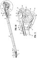
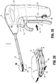
- Instrument 10 is configured for grasping, treating, and/or dissecting tissue and may find particular applicability for use in performing tonsillectomy and/or adenoidectomy procedures, although use of instrument 10 in various other surgical procedures is also contemplated and within the scope of the present disclosure.
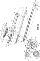
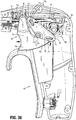
- instrument 10 generally includes a housing 20, a handle assembly 30, a trigger assembly 70, a shaft 80, an end effector assembly 100, a drive assembly 140, a knife assembly 170, and an energy activation assembly 190.
- shaft 80 extends distally from housing 20 and supports end effector assembly 100 at distal end 85 thereof
- drive assembly 140 operably couples handle assembly 30 with end effector assembly 100 to enable selective manipulation of jaw members 110, 120 of end effector assembly 100
- knife assembly 170 is operably coupled with trigger assembly 70 to enable selective translation of a knife blade 174 of knife assembly 170 relative to end effector assembly 100
- energy activation assembly 190 enables energy to be selectively delivered to end effector assembly 100.
- Instrument 10 may also include an electrosurgical cable (not shown) that connects instrument 10 to a generator (not shown) or other suitable power source, although instrument 10 may alternatively be configured as a battery-powered instrument.
- the electrosurgical cable includes lead wires, e.g., lead wires 107 ( FIG. 12 ), extending therethrough that have sufficient length to extend through housing 20 and shaft 80 in order to operably couple the generator, energy activation assembly 190, and end effector assembly 100 with one another to enable the selective supply of energy to electrically-conductive plates 112, 122 of jaw members 110, 120 of end effector assembly 100, e.g., upon activation of activation switch 194 of energy activation assembly 190.
- housing 20 houses the internal working components of instrument 10 and is formed from first and second housing components 22a, 22b configured to engage one another via a plurality of pin-aperture engagements 23 spaced around the perimeter of housing 20.
- Housing 20 defines a pistol-style configuration having a longitudinally-extending barrel portion 24 and a fixed handle portion 26 that extends from barrel portion 24 in generally perpendicular orientation relative thereto.
- Housing 20 movable handle 40 of handle assembly 30, and trigger 72 of trigger assembly 70 are ergonomically configured to enable operable grasping of instrument 10 in a plurality of different positions.
- Movable handle 40 defines a grasping portion 42 having an elongated proximal leg 43 that extends the length of fixed handle portion 26 of housing 20, a proximal foot 44 disposed at the free end of proximal leg 43 and angled distally relative to proximal leg 43, and an arcuate segment 45 disposed at the opposite end of proximal leg 43 and extending distally therefrom.
- Arcuate segment 45 culminates in a distal tail 46 and defines a sufficient diameter so as to operably receive a user's finger between distal tail 46 and proximal leg 43.
- Trigger 72 more specifically, includes a concave trigger surface 73 defining a saddle 74 configured to help retain a user's finger therein.
- the user's hand in a first operable grasping position, is positioned such that the thumb is partially received within waist 28, the tip of the index finger extends across trigger 72 and is partially received within saddle 74, the middle finger extends across movable handle 40 and is positioned adjacent arcuate segment 45 of movable handle 40 between proximal leg 43 and distal tail 46, and the ring finger and pinky are positioned distally of and adjacent to proximal leg 43.
- waist 28 inhibits slipping of the thumb
- saddle 74 inhibits slipping of the index finger
- proximal leg 43 and distal tail 46 retain the middle finger therebetween to enable both proximal and distal movement of movable handle 40
- proximal leg 43 provides a surface against which the ring finger and pinky can be utilized to urge movable handle 40 proximally
- proximal foot 44 inhibits slipping of the ring finger and pinky off the free end of movable handle 40.
- the user's hand in a second operable grasping position, is positioned such that the index finger is partially received within elongated indentation 27 on the opposite side of housing 20, the middle finger extends transversely across trigger 72 and is partially received within saddle 74, the ring finger extends across movable handle 40 and is positioned adjacent arcuate segment 45 of movable handle 40 between proximal leg 43 and distal tail 46, and the pinky is positioned distally of and adjacent to proximal leg 43.
- elongated indentation 27 inhibits slipping of the index finger
- saddle 74 inhibits slipping of the middle finger
- proximal leg 43 and distal tail 46 retain the ring finger therebetween to enable both proximal and distal movement of movable handle 40
- proximal leg 43 provides a surface against which the pinky can be utilized to urge movable handle 40 proximally.
- the user's hand in a third operable grasping position, is positioned such that the thumb is wrapped around a free end of fixed handle portion 26 of housing 20, the index finger and middle finger are positioned proximally of and adjacent the free end of proximal leg 43 of movable handle 40, the ring finger extends across movable handle 40 and is positioned adjacent arcuate segment 45 of movable handle 40 between proximal leg 43 and distal tail 46, and the pinky extends across trigger 72 and is partially received within saddle 74.
- proximal foot 44 inhibits slipping of the index finger off the free end of movable handle 40
- proximal leg 43 and distal tail 46 retain the ring finger therebetween to enable both proximal and distal movement of movable handle 40
- proximal leg 43 provides a surface against which the index and middle fingers can be utilized to urge movable handle 40 proximally
- saddle 74 inhibits slipping of the pinky.
- fixed handle portion 26 of housing 20 defines a bay 29a configured to receive and support energy activation assembly 190, which is operable to initiate and terminate the delivery of energy to end effector assembly 100.
- Energy activation assembly 190 includes a depressible button 192 that is mechanically coupled to a switch 194 mounted within bay 29a of fixed handle portion 26 and is engagable by a button activation post 196 extending proximally from a proximal side of movable handle 40 upon movement of the movable handle 40 to the activated position, as detailed below.
- Switch 194 is configured to electrically communicate with end effector assembly 100 and the generator (not shown) via suitable electrical wiring, e.g., leads 107 ( FIG. 12 ), extending through housing 20, shaft 80, and/or an external cable (not shown) to enable energy to be supplied from the generator (not shown) to end effector assembly 100 upon activation of switch 194.
- barrel portion 24 of housing 20 defines a distal aperture 29b ( FIG. 7 ) configured to receive proximal end 82 of shaft 80 therein, and an engagement feature (not shown) extending inwardly from each of first and second housing components 22a, 22b for receipt within opposed apertures 83 defined through proximal end 82 of shaft 80 for securing proximal end 82 of shaft 80 within barrel portion 24 of housing 20.
- Shaft 80 extends distally from housing 20 and defines a generally rectangular cross-sectional configuration oriented such that the larger width dimension thereof extends laterally and the smaller height dimension thereof extends vertically. This configuration of shaft 80 relative to the orientation of jaw members 110, 120 ( FIG.
- shaft 80 includes a pair of spaced-apart clevis members 84 extending from the top and bottom walls, e.g., the larger width dimension walls, of shaft 80 at distal end 85 thereof, each of which defines an aperture 86 for receiving a pivot pin 103 to operably support end effector assembly 100 at distal end 85 of shaft 80.
- apertures 86 are vertically-aligned with one another.
- Shaft 80 further includes, as noted above, opposed apertures 83 defined through the side walls, e.g., the smaller height dimension walls, of shaft 80 at proximal end 82 thereof for receiving engagement features (not shown) extending inwardly from first and second housing components 22a, 22b to secure proximal end 82 of shaft 80 within housing 20.
- Barrel portion 24 of housing further includes a pair of pivot apertures 29c, a longitudinal track 29d ( FIG. 13 ), a pivot boss 29e, and a retention pin 29f.
- Each pivot aperture 29c is defined on the inwardly-facing surface of one of first and second housing components 22a, 22b (only pivot aperture 29c of first housing component 22a is shown) and is configured to receive pivot pin 48 to pivotably couple movable handle 40 and trigger 72 to housing 20.
- Longitudinal track 29d ( FIG. 13 ) is defined on the inwardly-facing surface of first housing component 22a and is configured to guide translation of drive assembly 140 relative to housing 20.
- Pivot boss 29e extends inwardly from first housing component 22a and is configured to pivotably couple linkage 76 of trigger assembly 70 to housing 20.
- Retention pin 29f extends inwardly from first housing component 22a and is configured to retain a fixed end 71a of biasing member 71 of trigger assembly 70 in fixed position relative to housing 20.
- handle assembly 30 includes a movable handle 40 that is movable relative to fixed handle portion 26 of housing 20 between an initial position, a compressed position, and an activated position, as explained in greater detail below, to impart movement of jaw members 110, 120 of end effector assembly 100 between a spaced-apart position and an approximated position for grasping tissue therebetween and for initiating the supply of energy to end effector assembly 100 for treating grasped tissue.
- Movable handle 40 includes grasping portion 42, detailed above, which extends from housing 20 adjacent fixed handle portion 26, and flange portion 47, which extends upwardly into housing 20. Flange portion 47 is pivotably coupled within housing 20 at the free end of flange portion 47 via pivot pin 48.
- Pivot pin 48 is engaged within and extends between pivot apertures 29c of first and second housing components 22a, 22b of housing 20 to permit movable handle 40 to pivot about pivot pin 48 and relative to housing 20 between the initial position, the compressed position, and the activated position.
- Pivot pin 48 is disposed on one side of, e.g., above, drive assembly 140, while grasping portion 42 of movable handle 40 is disposed on the other side of, e.g., below, drive assembly 140, to provide a mechanical advantage when actuating movable handle 40.
- Flange portion 47 of movable handle 40 further includes a cut-out 49 defined therein and an engagement bulge 51 protruding therefrom.
- Cut-out 49 is configured to slidably receive drive plate 142 of drive assembly 140 and knife plate 172 of knife assembly 170.
- Engagement bulge 51 is configured to operably engage flange portion 47 of movable handle 40 with slider assembly 150 of drive assembly 140, as detailed below.
- Drive assembly 140 includes drive plate 142 and slider assembly 150.
- Drive plate 142 extends distally from housing 20 and through shaft 80 to operably engage end effector assembly 100 such that, as detailed below, translation of drive plate 142 through shaft 80 and relative to end effector assembly 100 pivots jaw members 110, 120 of end effector assembly 100 between the spaced-apart and approximated positions.
- Slider assembly 150 operably couples flange portion 47 of movable handle 40 with drive plate 142 such that pivoting of movable handle 40 between the initial position and the compressed position pivots jaw members 110, 120 of end effector assembly 100 between the spaced-apart and approximated positions, while ensuring application of an appropriate closure force or closure force within an appropriate closure force range to tissue grasped between jaw members 110, 120 in the approximated position thereof.
- Slider assembly 150 includes a proximal housing 152, a distal extension 154 extending distally from proximal housing 152, and a mandrel 156 disposed at the distal end of distal extension 154.
- Proximal housing 152 includes a post 153a configured to receive a torsion spring 160 thereabout, a first slot 153b configured to retain a first leg 161 of torsion spring 160 therein in fixed relation relative thereto, and a second slot 153c configured to operably receive second leg 162 of torsion spring 160 therein.
- Proximal housing 152 further includes an abutment rib 153d disposed thereon adjacent second slot 153c, and a flange member 153e configured for receipt within longitudinal track 29d ( FIG. 13 ) of first housing component 22a of housing 20.
- FIG. 11A another slider assembly 2150 provided in accordance with the present disclosure is similar to slider assembly 150 ( FIGS. 10- 11 ) except for the configuration of the proximal housing and spring; thus, only these differences are detailed below.
- Proximal housing 2152 of slider assembly 2150 is configured to house a compression spring 2160 therein.
- Compression spring 2160 defines a first end 2161 and a second end 2162. First end 2161 of compression spring 2160 is engaged with a vertical plate. Second end 2162 of compression spring 2160 is engaged with an inner wall of proximal housing 2152.
- compression spring 2160 functions similar to torsion spring 160 ( FIGS. 10-11 ), as detailed below, except that, rather than being further tensioned via application of a torsional force thereto, compression spring 2160 is further tensioned via application of a compressive force thereto.
- Mandrel 156 is disposed at the distal end of distal extension 154 of slider assembly 150.
- Mandrel 156 includes a pair of spaced-apart walls 157 defining a channel 158 therebetween.
- Channel 158 is configured to receive engagement bulge 51 of flange portion 47 of movable handle 40 while permitting vertical sliding of engagement bulge 51 within channel 158.
- engagement bulge 51 is urged into contact with one of the walls 157 defining channel 158 to thereby translate slider assembly 150 within housing 20.
- the vertical sliding of engagement bulge 51 within channel 158 during such urging ensures that slider assembly 150 is translated longitudinally within and relative to housing 20 despite the arcuate travel of movable handle 40 as movable handle is pivoted about pivot pin 48 relative to housing 20.
- Drive plate 142 includes a flange 143 disposed at the proximal end thereof.
- Flange 143 defines an aperture 144 configured to receive second leg 162 of torsion spring 160 therein such that translation of second leg 162 of torsion spring 160 relative to housing 20 effects corresponding translation of drive plate 142 relative to housing 20.
- vertical plate 2163 is engaged within a slot 2144 defined within drive plate 142 (see FIG. 11A ), and functions in a similar manner as detailed below with respect to slider assembly 150.
- Flange 143 further defines a proximal edge 145 configured to abut abutment rib 153d of proximal housing 152 in a proximal-most position of drive plate 142 relative to slider assembly 150 to inhibit further proximal movement of drive plate 142 relative to slider assembly 150.
- Drive plate 142 extends distally from housing 20 and through shaft 80 to operably engage end effector assembly 100.
- Drive plate 142 is oriented similarly to shaft 80, e.g., such that the width of drive plate 142 extends along the width dimension of shaft 80.
- Drive plate 142 further defines a track edge 146 extending along a portion of each longitudinal side thereof. Track edges 146 are configured to slidably receive knife plate 172, as detailed below.
- a cam-pin aperture 147 configured to receive a cam pin 105 associated with end effector assembly 100 is defined transversely through drive plate 142 towards the distal end of drive plate 142.
- a mouth 149 configured to receive a pivot pin 103 associated with end effector assembly 100 is defined at the distal end of drive plate 142.
- a torsion spring 1160 may be operably coupled between movable handle 40 and drive plate 142 without a slider assembly. More specifically, in some embodiments, torsion spring 1160 is mounted about a post 1153a extending transversely from movable handle 40 and includes a first leg 1161 and a second leg 1162.
- First leg 1161 of torsion spring 1160 is configured for receipt within an aperture 1144 defined through drive plate 142 to operably couple movable handle 40 with drive plate 142, while second leg 1162 of torsion spring 1160 is fixed relative to movable handle 40 via abutment with a protrusion 1153c thereof.
- torsion spring 1160 operates similarly to torsion spring 160 ( FIGS. 10-11 ) and, thus, a separate description of the use of torsion spring 1160 is omitted as being superfluous.
- end effector assembly 100 is operably supported at distal end 85 of shaft 80 and includes opposing jaw members 110, 120 pivotably coupled to one another and movable relative to one another and shaft 80 between a spaced-apart position and an approximated position for grasping tissue therebetween.
- Each jaw member 110, 120 includes an electrically-conductive plate 112, 122, a jaw frame 113, 123, a spacer 115 (only spacer 115 of jaw member 110 is shown ( FIG. 21 )), and an outer housing 118, 128, each of which is detailed below.
- Jaw members 110, 120 define curved configurations, wherein jaw members 110, 120 bend upwardly from a longitudinal axis of shaft 80, e.g., towards the upper, larger width dimension wall of shaft 80. This configuration facilitates use of instrument 10 in tonsillectomy and adenoidectomy procedures as well as other surgical procedures and allows for increased visualization of the surgical site in these and other procedures. Except where specifically noted otherwise, jaw members 110, 120 define mirror-image configurations of one another.
- Jaw frames 113, 123 of jaw members 110, 120 each include a pair of spaced-apart proximal flanges 113a, 123a and a distal jaw support 113b, 123b. Jaw frames 113, 123 are formed via stamping and made from stainless steel, although other manufacturing processes and/or materials for forming jaw frames 113, 123 are also contemplated. Proximal flanges 113a of jaw member 110 are spaced-apart further than proximal flanges 123a of jaw member 120 so as to allow proximal flanges 123a of jaw member 120 to be positioned between proximal flanges 113a of jaw member 110 during assembly.
- proximal flanges 113a, 123a of each pair define aligned pivot apertures 114a, 124a and aligned cam slots 114b, 124b.
- Pivot pin 103 of end effector assembly 100 is configured for vertical insertion through apertures 86 of clevis members 84 of shaft 80 and pivot apertures 114a, 124a to pivotably couple jaw members 110, 120 to shaft 80 and one another with jaw members 110, 120 being laterally movable, e.g., along the larger width dimension of shaft 80, between the spaced-apart and approximated positions.
- Pivot pin 103 is configured to at least partially enter mouth 149 of drive plate 142 to permit drive plate 142 to slide further distally relative to end effector assembly 100 to a position wherein mouth 149 of drive plate 142 at least partially surrounds pivot pin 103.
- cam slots 114b of proximal flanges 113a of jaw member 110 are oppositely angled relative to the cam slots 124b of proximal flanges 123a of jaw member 120.
- Cam pin 105 of end effector assembly 100 is configured for insertion through each cam slot 114b, 124b as well as cam-pin aperture 147 of drive plate 142 to operable couple drive plate 142 with jaw members 110, 120 such that translation of drive plate 142 relative to jaw members 110, 120 pivots jaw members 110, 120 about pivot pin 103 and relative to one another and shaft 80 between the spaced-apart and approximated positions.
- jaw members 110, 120 defines a mirror-image configurations of one another (unless specifically contradicted herein) and, thus, any description and/or illustration of one jaw member 110, 120 applies similarly to the other jaw member 110, 120.
- Distal jaw support 113b of jaw frame 113 of jaw member 110 extends distally from proximal flange 113a and defines a generally "L-shaped" configuration.
- Distal jaw support 113b is configured to support electrically-conductive plate 112, spacer 115, and outer housing 118 of jaw member 110 thereon.
- distal jaw support 113b do not extend distally the entire length of jaw member 110. Rather, distal jaw support 113b defines a length of about 50% to about 75% of the lengths of electrically-conductive plate 112, spacer 115, and outer housing 118 such that about 25% to about 50% of the lengths of these components extend distally beyond distal jaw support 113b.
- Spacer 115 of jaw member 110 defines a generally "M-shaped" configuration, is formed from an electrically-insulative material, and is overmolded onto distal jaw support 113b during a first overmold, although other manufacturing processes are also contemplated.
- Spacer 115 defines a body 116a and a pair of wings 116b surrounding body 116a. Spacer 115 is positioned to electrically-isolate electrically-conductive plate 112 and distal jaw support 113b from one another.
- a knife slot 116c extends longitudinally through body 116a of spaced 115 and is generally centered relative to body 116a.
- Knife slot 116c is open only to the top of spacer 115, except for the distal portion thereof, which extends beyond distal jaw support 113b and is open on both the top and bottom sides thereof to provide a window 116d.
- a support-receiving channel 116e extends longitudinally through body 116a at a position laterally offset relative to knife slot 116c so as to not interfere therewith.
- Support-receiving channel 116e is open to the bottom of spacer 115 and is configured to receive the upright of the "L-shaped" distal jaw support 113b upon the first overmolding of spacer 115 thereabout.
- Body 116a of spacer 115 further defines a tunnel 116f configured to permit passage of lead wire 107 therethrough.
- each jaw member 110, 120 defines a generally planar tissue-contacting surface 112a, 122a, an elongated slot 112b, 122b extending through the respective tissue-contacting surface 112a, 122a, a pair of legs 112c, 122c extending downwardly from each side of the respective tissue-contacting surface 112a, 122b, and a distal edge 112d, 122d disposed at the distal end of the respective tissue-contacting surface 112a, 122a.
- Electrically-conductive plates 112, 122 extend from the proximal heels of jaw members 110, 120, e.g., the interface between flanges 113a, 123a and the distal portions of jaw members 110, 120, to the distal tips of jaw members 110, 120.
- Jaw housing 118 of jaw member 110 includes a pair of proximal tissue stops that extend therefrom about either side of jaw member 120 such that, in conjunction with the positioning of electrically-conductive plates 112, 122 at the proximal heel of jaw members 110, 120, grasping of tissue proximally of electrically-conductive plates 112, 122 is inhibited.
- Tissue-contacting surfaces 112a, 122a define a plurality of spaced-apart recesses 112e, 122e therein that facilitate grasping tissue.
- Tissue-contacting surface 112a of electrically-conductive plate 112 of jaw member 110 and/or tissue-contacting surface 122a of electrically-conductive plate 122 of jaw member 120 may further include a plurality of stop members 122f disposed thereon.
- Stop members 122f may be constructed of a heat-resistant ceramic deposited onto the tissue-contacting surfaces 112a, 122a, an electrically non-conductive plastic molded onto tissue-contacting surfaces 112a, 122a, an electrical conductive material isolated from the respective tissue-contacting surface 112a, 122a, or may be formed from and/or manufactured in any other suitable fashion.
- Each wing 116b of spacer 115 of jaw member 110 defines a slot 116g, open at the top end thereof, that is configured for receiving one of the legs 112c of electrically-conductive plate 112.
- Wire 107 which extends through tunnel 116f defined within spacer 115 is configured to electrical connect to an underside of electrically-conductive plate 112 towards the distal end thereof for enabling the selective supply of energy thereto.
- Wire 107 is configured to extend proximally through shaft 80 and into housing 20, ultimately coupling to energy activation assembly 190 ( FIG. 7 ) and/or extending through the cable (not shown) to couple to the generator (not shown).
- Outer housings 118, 128 are formed about jaw members 110, 120 via a second overmold process, such that each outer housing 118, 128 partially encloses respective jaw members 110, 120 with the exception of a portion of the distal jaw support 113b, 123b thereof and the tissue-contacting surface 112a, 122a thereof, which remain exposed.
- legs 112c, 122c of electrically-conductive plates 112, 122 of jaw members 110, 120 and the spacers 115 (only spacer 115 of jaw member 110 is shown) thereof each define a plurality of fill-apertures 122g (only fill-apertures 122g of electrically-conductive plate 122 of jaw member 120 are illustrated) that, upon overmolding of outer housings 118, 128 about respective jaw members 110, 120 are filled with the overmolded material forming outer housings 118, 128 to lock the components of each jaw member 110, 120 in an assembled condition.
- outer housings 118, 128 define lengths extending along the sides of respective jaw members 110, 120 and thicknesses that decrease in the proximal-to-distal direction along the lengths thereof. Outer housings 118, 128 also define windows 119, 129 that align with and communicate with the windows 116d of the respective spacers 115 (only spacer 115 of jaw member 110 is illustrated) and the knife slots 112b, 122b of the respective electrically-conductive plate 112, 122 thereof so as to define an opening 131, 132 extending through the distal portion of each jaw member 110, 120 transversely relative to the plane defined by the respective tissue-contacting surface 112a, 122a.
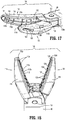
- distal edges 112d, 122d of electrically-conductive plates 112, 122 overlap the distal ends of outer housings 118, 128 such that, as illustrated in FIGS. 15 and 16 , distal edges 112d, 122d can be utilized to pinch tissue therebetween.
- this configuration enables pinching of planar tissue structures that lack substantial protruding portions that would otherwise enable grasping, such as the tissue wall illustrated in FIGS. 15 and 16 .
- jaw members 110, 120 may further be utilized to spread and/or dissect tissue.
- end effector assembly 100 may be manipulated such that the distal tips of jaw members 110, 120 are pressed into contact with tissue to be spread and/or dissected, as shown in FIG. 15A .
- jaw members 110, 120 are moved to the spaced-apart position such that the distal ends of outer housings 118, 128 of jaw members 110, 120, respectively, push tissue in opposite directions, thus spreading and/or dissecting tissue.
- drive assembly 140 defines a pre-loaded configuration wherein drive assembly 140 ( FIG. 12 ) is always under tension, such that backlash upon moving jaw members 110, 120 from the approximated position back to the spaced-apart position is eliminated.
- Such a configuration facilitates spreading and/or dissecting tissue by allowing for a more smooth and consistent transition of jaw members 110, 120 from the approximated position back to the spaced-apart position.
- the distal ends of outer housings 118, 128 of jaw members 110, 120 define cut-outs that form shelves 118b, 128b between the distal ends of outer housings 118, 128 and the body portions 118a, 128a of housings 118, 128, respectively.
- Shelves 118b, 128b, as shown in FIGS. 15B, 15B', and 16B facilitate the retention of tissue via the distal ends of outer housings 118, 128, thus inhibiting slipping of tissue and facilitating spreading and/or dissecting tissue.
- the distal ends of outer housings 118, 128 of jaw members 110,120 define extensions 118c, 128c that are relatively narrow and relatively small-radiused as compared to body portions 118a, 128a of housings 118, 128.
- These extensions 118c, 128c facilitate pressing the distal ends of jaw members 110, 120 further into tissue (see FIG. 15C ) to ensure a relatively large contact area of tissue against shelves 118b, 128b upon moving jaw members 110, 120 to the spaced-apart position (see FIG. 16C ), thus facilitating the spreading and/or dissecting of tissue.
- the distal ends of outer housings 118, 128 of jaw members 110, 120 are cut-back to define angled surfaces 118d, 128d that define an angle " ⁇ " relative to the perpendicular extending from the distal ends of jaw members 110, 120 (see FIG. 16D ).
- Angled surfaces 118d, 128d similarly as with the previous embodiments, facilitate the pressing of the distal ends of jaw members 110, 120 further into tissue (see FIG. 15D ) as well as the retention of tissue while spreading and/or dissecting tissue.
- Trigger assembly 70 is operably coupled to knife assembly 170 to enable selective translation of knife blade 174 of knife assembly 170 relative to end effector assembly 100.
- Trigger assembly 70 includes trigger 72 and a linkage 76.
- Trigger 72 includes a grasping portion 75a which includes the concave trigger surface 73, a pivot extension 75b extending upwardly from grasping portion 75a, and a proximal extension 75c extending proximally from grasping portion 75a.
- Grasping portion 75a also includes a tab 75d extending distally therefrom.
- Tab 75d defines an aperture 75e configured to retain movable end 71b of biasing member 71 therein.
- fixed end 71a of biasing member 71 is engaged via retention pin 29f of first housing component 22a of housing 20. In this manner, biasing member 71 serves to bias trigger 72 distally towards an un-actuated position ( FIG. 35 ).
- Pivot extension 75b of trigger 72 is pivotably coupled to housing 20 via pivot pin 48, which is engaged within and extends between pivot apertures 29c of first and second housing components 22a, 22b of housing 20. It is noted that pivot pin 48 is shared by both trigger 72 and movable handle 40; that is, both trigger 72 and movable handle 40 are pivotable about the same point relative to housing 20.
- Proximal extension 75c of trigger 72 includes a post 75f that, as detailed below, is operably engaged within cam slot 77e of linkage 76.
- Linkage 76 serves to operably couple trigger 72 with knife assembly 170 such that pivoting of trigger 72 from the un-actuated position ( FIG. 35 ) to the actuated position ( FIG. 36 ) advances knife blade 174 relative to end effector assembly 100 to cut tissue grasped between jaw members 110, 120, as detailed below.
- Linkage 76 defines a generally triangular-shaped configuration including an apex 77a pointing in a distal direction and a base defining upper and lower corners 77b, 77c, respectively.
- Apex 77a includes a peg 77d that is configured for receipt within pivot boss 29e of first housing component 22a to pivotably couple linkage 76 relative to housing 20 about apex 77a thereof.
- a cam slot 77e, 77f is defined through linkage 76 adjacent upper and lower corners 77b, 77c, respectively.
- a coupling pin 78 operably couples cam slot 77e with knife plate 172 of knife assembly 170. More specifically, coupling pin 78 includes a cap 79a defining a slot 79c ( FIG. 9 ) configured to receive finger 173 of knife plate 172 and a rod 79b that is operably engaged within cam slot 77e. As noted above, post 75f of proximal extension 75c of trigger 72 is operably engaged within cam slot 77f.
- trigger assembly 70 pivoting of trigger 72 between the un-actuated and actuated positions ( FIGS. 35 and 36 , respectively) urges linkage 76 to pivot relative to housing 20 ultimately such that coupling pin 78 is urged to translate longitudinally within and relative to housing 20.
- coupling pin 78 As finger 173 of knife plate 172 is engaged with coupling pin 78, such longitudinal translation of coupling pin 78 is imparted to knife plate 172 for translating knife blade 174 between retracted and extended positions ( FIGS. 29-34 and 38-40 , respectively) relative to end effector assembly 100, as detailed below.
- Knife assembly 170 includes a knife plate 172 defining a finger 173 at the proximal end thereof. Knife plate 172 extends distally through housing 20 and shaft 80 atop drive plate 142 and is slidably engaged therewith via receipt of each end of knife plate 172 within track edges 146 of drive plate 142. Knife assembly 170 further includes knife blade 174 integrally formed with or otherwise engaged to knife plate 172 and extending distally therefrom. Knife blade 174 defines a width less than the combined thickness of jaw members 110, 120 at the proximal ends thereof but greater than or equal to the combined thickness of jaw members 110, 120 at the distal ends thereof.
- Knife blade 174 further defines an elongated opening 176 extending longitudinally therethrough.
- Elongated opening 176 permits knife blade 174 to be slidably disposed about pivot pin 103 and cam pin 105. More specifically, elongated opening 176 defines a first portion 177a having a first width configured to slidably receive pivot pin 103 and a second portion 177b having a second width configured to slidably receive cam pin 105 but sufficiently small to inhibit receipt of the larger-diameter pivot pin 103 therein.
- handle assembly 30, slider assembly 150 of drive assembly 1450, and trigger assembly 70 enable efficient assembly of instrument 10 in that these components may be operably positioned within housing 20 and relative to one another via a top-down assembly process.
- FIGS. 22-40 the use and operation of instrument 10 is described.
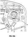
- movable handle 40 is disposed in the initial position and, correspondingly, jaw members 110, 120 are disposed in the spaced-apart position. More specifically, with movable handle 40 in the initial position, engagement bulge 51 is disposed in a distal-most position such that slider assembly 150 is disposed in a distal-most position. With slider assembly 150 disposed in its distal-most position, torsion spring 160 is less-tensioned and second leg 162 of torsion spring 160 retains drive plate 142 in a distal-most position.
- Torsion spring 160 is less-tensioned but not fully un-tensioned in the initial position of movable handle 40. This configuration maintains a pre-load on drive assembly 140 such that, as noted above, backlash due to the complete removal of tension from torsion spring 160 as jaw members 110, 120 move from the approximated position back to the spaced-apart position is eliminated.
- Drive plate 142 is inhibited from moving proximally relative to slider assembly 150 in this position due to the abutment of the proximal edge 145 of drive plate 142 with abutment rib 153d of proximal housing 152 of slider assembly 150. Further, in this distal-most position of drive plate 142, drive plate 142 maintains cam pin 105 at the distal ends of cam slots 114b, 124b and, thus, jaw members 110, 120 are maintained in the spaced-apart positon.
- a torsion spring 3160 may be provided including a first leg 3161 that extends through a slot 3153b defined within proximal housing 152 and is positioned to abut a block 3020 mounted within or monolithically formed with housing 20.
- torsion spring 3160 provides the additional function of biasing slider assembly 150 distally, thereby biasing jaw members 110, 120 towards the spaced-apart position (see FIG. 14 ). That is, upon movement of movable handle 40 to translate slider assembly 150 proximally (see FIG.
- first leg 3161 of torsion spring 3160 is maintained in position via its abutment with block 3020, thereby further tensioning torsion spring 3160 such that, upon release of movable handle 40 ( FIG. 9 ), torsion spring 3160 serves to bias slider assembly 150 distally, thereby biasing jaw members 110, 120 towards the spaced-apart position (see FIG. 14 ).
- multiple blocks 3020 may be provided at different positions within housing 20 such that, during assembly, first leg 3161 of torsion spring 3160 may be positioned to abut a selected one of the blocks 3020 to achieve a desired biasing force.
- trigger 72 is initially is disposed in the un-actuated position and, accordingly, knife blade 174 is disposed in the retracted position. More specifically, in the un-actuated position, trigger 72 is disposed in a distal-most position under the bias of biasing member 71 such that lower corner 77c of linkage 76, which is coupled to trigger 72 via engagement of post 75f within slot 77f, is disposed in a distal-most position.
- upper and lower corners 77b, 77c of linkage 76 are disposed on opposite sides of apex 77a, with lower corner 77c disposed in its distal-most position, upper corner 77b is disposed in a proximal-most position. With upper corner 77b disposed in its proximal-most position, knife plate 172 is likewise disposed in a proximal-most position due to the engagement of pin 78 within slot 77e.
- the proximal-most position of knife plate 172 corresponds to the retracted position of knife blade 174, wherein knife blade 174 is disposed between flanges 113a, 123a of jaw members 110, 120 but does not extend distally therefrom so as to avoid interference with tissue disposed between jaw members 110, 120. Further, in this position, pivot pin 103 is disposed at the distal end of first portion 177a of opening 176 of knife blade 174 and cam pin 105 is likewise disposed within first portion 177a of opening 176.
- movable handle 40 in order to move jaw members 110, 120 to the approximated position to grasp tissue therebetween, movable handle 40 is pulled proximally towards fixed handle portion 26 from the initial position ( FIG. 22 ) to the compressed position ( FIG. 27 ).
- engagement bulge 51 of movable handle 40 is moves proximally relative to housing 20, thereby urging slider assembly 150 proximally through housing 20.
- Torsion spring 160 in the less-tensioned state, is translated proximally together with slider assembly 150 such that second leg 162 of torsion spring 160 pulls drive plate 142 proximally in connection with the proximal translation of slider assembly 150.
- slider assembly 150 and drive plate 142 move in concert with one another.
- cam pin 105 is pulled proximally through cam slots 114b, 124b such that jaw members 110, 120 are pivoted from the spaced-apart position to the approximated position to grasp tissue therebetween.
- Drive plate 142 is still inhibited from moving proximally relative to slider assembly 150 in this position due to the abutment of the proximal edge 145 of drive plate 142 with abutment rib 153d of proximal housing 152 of slider assembly 150.
- instrument 10 may be utilized as a pliers to maneuver, manipulate, and/or reposition tissue.
- jaw members 110, 120 may be approximated adjacent a wall of tissue to pinch tissue between the distal tips of jaw members 110, 120 to enable maneuvering, manipulating, and/or repositioning thereof.
- movable handle 40 in order to apply energy to tissue grasped between jaw members 110, 120 to treat tissue, movable handle 40 is compressed further towards fixed handle portion 26 to an activation position, wherein an appropriate closure force or closure force within an appropriate range, is achieved and energy activation is initiated.
- an appropriate closure force or closure force within an appropriate range is imparted to tissue grasped between electrically-conductive plates 112, 122 of jaw members 110, 120 regardless of the thickness or compressibility of tissue or the position of movable handle 40. This is because, upon movement of movable handle 40 from the compressed position towards the activation position, slider assembly 150 is translated proximally while drive plate 142 is maintained in position.
- slider assembly 150 and drive plate 142 no longer move in concert with one another. Rather, as detailed below, slider assembly 150 and drive plate 142 are decoupled to permit relative motion therebetween.
- torsion spring 160 The decoupling of slider assembly 150 and drive plate 142 to permit relative motion therebetween is provided via torsion spring 160 according to the invention. More specifically, upon proximal movement of movable handle 40, a first force is imparted from movable handle 40, through slider assembly 150, first leg 161 of torsion spring 160, the body of torsion spring 160, and second leg 162 of torsion spring 160, to drive plate 142 to urge drive plate 142 in a proximal direction, while a second, opposite force acts on drive plate 142 and, thus, second leg 162 of torsion spring 160 in a distal direction to resist further compression of tissue between jaw members 110, 120.
- torsion spring 160 may be configured such that the second, opposite force exceeds the spring force of torsion spring 160 at a force corresponding to a closure pressure on tissue between 3 kg/cm 2 to 16 kg/cm 2 , as it has been found that closure forces within this range facilitate sealing of tissue grasped between jaw members 110, 120.
- other forces and/or force ranges are also contemplated, e.g., for treating tissue in other manners (coagulating, cauterizing, etc.).
- button activation post 196 ( FIG. 7 ) of movable handle 40 contacts depressible button 192 sufficiently so as to depress depressible button 192 into fixed handle portion 26 to activate switch 194.
- Switch 194 is disposed in electrical communication with the generator (not shown) and electrically-conductive plates 112, 122 of jaw members 110, 120, respectively, such that activation of switch 194 initiates the supply of energy to electrically-conductive plates 112, 122 to treat, e.g., coagulate, cauterize, and/or seal, tissue grasped therebetween.
- knife blade 174 may be advanced between jaw members 110, 120 to cut tissue grasped therebetween.
- trigger 72 is pulled proximally against the bias of biasing member 71 from the un-actuated position to the actuated position.
- post 75f is pushed proximally to urge linkage 76 to pivot counter-clockwise (from the orientation illustrated in FIG. 36 ) such that upper corner 77b of linkage 76 is moved distally.
- knife plate 172 moves from the un-actuated position to the actuated position urges knife plate 172 distally. More specifically, knife plate 172 is urged distally such that knife blade 174 is advanced distally from the retracted position to the extended position. As knife blade 174 is advanced distally, knife blade 174 enters the knife slots of jaw members 110, 120 defined by the respective knife slots 112b, 122b of electrically-conductive plates 112, 122 and the knife slots 116c of the respective spacers 115 (only spacer 115 of jaw member 110 is illustrated). As can be appreciated, translation of knife blade 174 through the knife slots of jaw members 110, 120 to the extended position thereof divides tissue grasped between jaw members 110, 120.
- knife blade 174 defines a width greater than or equal to the combined thickness of jaw members 110, 120 at the distal ends thereof, as knife blade 174 is advanced distally through the knife slots, knife blade 174 may extend at least partially through windows 119, 129 and openings 131, 132 of jaw members 110, 120, depending upon the thickness of tissue grasped between jaw members 110, 120 (see FIG. 39 ). Further, as knife blade 174 is advanced distally, pivot pin 103 and cam pin 105 translate proximally along opening 176 eventually such that cam pin 105 extends through second portion 177b of opening 176. As pivot pin 103 is too large to extend into second portion 177b of opening 176, interference therebetween defines the distal-most extent of travel of knife blade 174. However, other components of knife assembly 170 and/or trigger assembly 70 may additionally or alternatively inhibit the extension of knife blade 174.
- trigger 72 and knife plate 172 are returned proximally under the bias of biasing member 71 such that knife blade 174 is returned to the retracted position. Thereafter, movable handle 40 may be returned to the initial position to release the treated and/or divided tissue.
- the various embodiments disclosed herein may also be configured to work with robotic surgical systems and what is commonly referred to as "Telesurgery.”
- Such systems employ various robotic elements to assist the surgeon and allow remote operation (or partial remote operation) of surgical instrumentation.
- Various robotic arms, gears, cams, pulleys, electric and mechanical motors, etc. may be employed for this purpose and may be designed with a robotic surgical system to assist the surgeon during the course of an operation or treatment.
- Such robotic systems may include remotely steerable systems, automatically flexible surgical systems, remotely flexible surgical systems, remotely articulating surgical systems, wireless surgical systems, modular or selectively configurable remotely operated surgical systems, etc.
- the robotic surgical systems may be employed with one or more consoles that are next to the operating theater or located in a remote location.
- one team of surgeons or nurses may prep the patient for surgery and configure the robotic surgical system with one or more of the instruments disclosed herein while another surgeon (or group of surgeons) remotely control the instruments via the robotic surgical system.
- a highly skilled surgeon may perform multiple operations in multiple locations without leaving his/her remote console which can be both economically advantageous and a benefit to the patient or a series of patients.
- the robotic arms of the surgical system are typically coupled to a pair of master handles by a controller.
- the handles can be moved by the surgeon to produce a corresponding movement of the working ends of any type of surgical instrument (e.g., end effectors, graspers, knifes, scissors, etc.) which may complement the use of one or more of the embodiments described herein.
- the movement of the master handles may be scaled so that the working ends have a corresponding movement that is different, smaller or larger, than the movement performed by the operating hands of the surgeon.
- the scale factor or gearing ratio may be adjustable so that the operator can control the resolution of the working ends of the surgical instrument(s).
- the master handles may include various sensors to provide feedback to the surgeon relating to various tissue parameters or conditions, e.g., tissue resistance due to manipulation, cutting or otherwise treating, pressure by the instrument onto the tissue, tissue temperature, tissue impedance, etc. As can be appreciated, such sensors provide the surgeon with enhanced tactile feedback simulating actual operating conditions.
- the master handles may also include a variety of different actuators for delicate tissue manipulation or treatment further enhancing the surgeon's ability to mimic actual operating conditions.
Landscapes
- Health & Medical Sciences (AREA)
- Surgery (AREA)
- Life Sciences & Earth Sciences (AREA)
- Engineering & Computer Science (AREA)
- Medical Informatics (AREA)
- General Health & Medical Sciences (AREA)
- Nuclear Medicine, Radiotherapy & Molecular Imaging (AREA)
- Veterinary Medicine (AREA)
- Biomedical Technology (AREA)
- Heart & Thoracic Surgery (AREA)
- Public Health (AREA)
- Molecular Biology (AREA)
- Animal Behavior & Ethology (AREA)
- Otolaryngology (AREA)
- Physics & Mathematics (AREA)
- Plasma & Fusion (AREA)
- Hematology (AREA)
- Dentistry (AREA)
- Oral & Maxillofacial Surgery (AREA)
- Pulmonology (AREA)
- Surgical Instruments (AREA)
- Prostheses (AREA)
Claims (15)
- Instrument chirurgical (10) comprenant :un boîtier (20) ;un arbre (80) s'étendant de manière distale du boîtier ;un ensemble effecteur terminal (100) couplé à une extrémité distale de l'arbre ;une poignée mobile (40) couplée au boîtier ; etun ensemble d'entraînement (140) couplant en service la poignée mobile et l'ensemble effecteur terminal, l'ensemble d'entraînement comprenant :un élément d'entraînement (149) configuré pour effectuer une translation à travers l'arbre et par rapport à l'ensemble effecteur terminal pour actionner l'ensemble effecteur terminal ; caractérisé par :
un ressort de torsion (160) comprenant une première branche (161) et une seconde branche (162), la première branche étant couplée en service à la poignée mobile et configurée pour effectuer une translation longitudinale à travers le boîtier en réponse à un déplacement de la poignée mobile par rapport au boîtier, la seconde branche étant couplée en service à l'élément d'entraînement et configurée pour effectuer une translation longitudinale à travers le boîtier en coopération avec la première branche pour ainsi convertir son mouvement longitudinal en mouvement longitudinal de l'élément d'entraînement lorsqu'une force agissant sur l'élément d'entraînement est inférieure à une force de seuil, la seconde branche étant configurée pour rester en position fixe, plaçant ainsi sous tension le ressort de torsion et retenant l'élément d'entraînement en position fixe en réponse à un mouvement longitudinal de la première branche lorsque la force agissant sur l'élément d'entraînement est égale ou supérieure à la force de seuil. - Instrument chirurgical selon la revendication 1, dans lequel l'ensemble d'entraînement comprend en outre un coulisseau (150) comprenant une partie de boîtier (152) y retenant en service le ressort de torsion et une partie de mandrin (156) couplée en service à la poignée mobile, le coulisseau étant configuré pour effectuer une translation longitudinale à travers le boîtier en réponse au mouvement de la poignée mobile par rapport au boîtier, de préférence dans lequel la première branche du ressort de torsion est engagée sur le boîtier pour solliciter le coulisseau et dans lequel la seconde branche du ressort de torsion est mobile par rapport à la partie de boîtier du coulisseau, plus de préférence dans lequel une partie de corps du ressort de torsion est supportée en rotation sur un montant (153a) disposé dans la partie de boîtier du coulisseau, le montant étant configuré pour permettre la mise en tension du ressort de torsion en réponse au déplacement de la première branche par rapport à la seconde branche.
- Instrument chirurgical selon la revendication 1, dans lequel la première branche (3161) du ressort de torsion (3160) est positionnée en service par rapport à un bloc (3020) disposé dans le boîtier pour presser l'élément d'entraînement par rapport au boîtier.
- Instrument chirurgical selon l'une quelconque des revendications précédentes, dans lequel la poignée mobile peut se déplacer par rapport au boîtier entre une position initiale, une position comprimée et une position activée, dans lequel la seconde branche est configurée pour effectuer une translation en coopération avec la première branche en réponse au mouvement de la poignée mobile entre les positions initiale et comprimée et dans lequel la seconde branche est configurée pour rester en position fixe en réponse au mouvement de la poignée mobile entre la position comprimée et la position activée.
- Instrument chirurgical selon l'une quelconque des revendications précédentes, dans lequel le ressort de torsion est pré-sollicité dans un état de moindre tension et dans lequel, en réponse au mouvement longitudinal de la première branche lorsque la force agissant sur l'élément d'entraînement est égale ou supérieure à la force de seuil, le ressort de torsion est en outre placé dans un état de plus grande tension.
- Instrument chirurgical selon la revendication 1, dans lequel l'ensemble effecteur terminal comprend un premier et un second élément de mors (110, 120), au moins l'un des premier et second éléments de mors étant mobile par rapport à l'autre entre une position espacée et une position rapprochée pour saisir un tissu qui se trouve entre eux, de préférence dans lequel (a) l'élément d'entraînement est configuré pour effectuer une translation à travers l'arbre et par rapport à l'ensemble effecteur terminal pour déplacer le premier et le second élément de mors entre les positions espacée et rapprochée.
- Instrument chirurgical selon la revendication 6, dans lequel au moins l'un des premier et second éléments de mors est adapté pour se connecter à une source d'énergie pour traiter le tissu saisi entre les premier et second éléments de mors, de préférence dans lequel l'instrument chirurgical comprend en outre un ensemble d'activation d'énergie (190) disposé sur le boîtier, l'ensemble d'activation d'énergie comprenant un commutateur (194) configuré pour fournir de l'énergie à au moins l'un des premier et second éléments de mors, plus de préférence dans lequel la poignée mobile peut se déplacer par rapport au boîtier entre une position initiale, une position comprimée et une position activée, dans lequel la seconde branche est configurée pour rester en position fixe en réponse au mouvement de la poignée mobile entre les positions comprimée et activée et dans lequel, en position activée, au moins une partie de la poignée est configurée pour venir en contact avec l'ensemble d'activation d'énergie afin d'activer le commutateur, encore plus de préférence dans lequel la seconde branche est configurée pour effectuer une translation en coopération avec la première branche en réponse au mouvement de la poignée mobile entre les positions initiale et comprimée de sorte que le premier et le second élément de mors appliquent une force de fermeture appropriée au tissu saisi entre eux et, le plus de préférence , dans lequel la force de fermeture appropriée est maintenue au cours du déplacement de la poignée mobile entre les positions comprimée et activée.
- Instrument chirurgical selon la revendication 1, dans lequel :le ressort de torsion comprend un corps et la seconde branche du ressort de torsion est engagée sur l'élément d'entraînement ;l'instrument chirurgical comprend un coulisseau (150) comprenant :un boîtier (152) comprenant un montant (153a) supportant en rotation le corps du ressort de torsion et configuré pour permettre le mouvement de la seconde branche du ressort de torsion par rapport au boîtier ; etun mandrin (156) s'étendant du boîtier, le mandrin étant couplé en service à la poignée mobile de sorte que le mouvement de la poignée mobile assure une translation longitudinale du coulisseau,lorsqu'une force agissant sur l'élément d'entraînement est inférieure à la force de seuil, le coulisseau et la seconde branche du ressort de torsion sont configurés pour effectuer une translation longitudinale à travers le boîtier en coopération l'un avec l'autre en réponse au mouvement de la poignée mobile, convertissant de la sorte le mouvement longitudinal du coulisseau en mouvement longitudinal de l'élément d'entraînement, et,lorsque la force agissant sur l'élément d'entraînement est égale ou supérieure à la force de seuil, le ressort de torsion étant placé sous tension en réponse au mouvement de la poignée mobile de sorte que la seconde branche du ressort de torsion et l'élément d'entraînement restent en position fixe au cours du mouvement longitudinal du coulisseau.
- Instrument chirurgical selon la revendication 8, dans lequel le ressort de torsion est pré-sollicité à un moindre état de tension et dans lequel, lorsque la force agissant sur l'élément d'entraînement est égale ou supérieure à la force de seuil, le ressort de torsion est en outre placé dans un plus grand état de tension.
- Instrument chirurgical selon la revendication 8, comprenant en outre un ensemble effecteur terminal (100) couplé en service à l'élément d'entraînement, l'élément d'entraînement étant configuré pour effectuer une translation par rapport à l'ensemble effecteur terminal pour actionner l'ensemble effecteur terminal, de préférence, dans lequel l'ensemble effecteur terminal comprend un premier et un second élément de mors (110, 120), au moins l'un des premier et second éléments de mors étant mobile par rapport à l'autre entre une position espacée et une position rapprochée pour saisir un tissu qui se trouve entre eux en réponse à la translation de l'élément d'entraînement par rapport à l'ensemble effecteur terminal.
- Instrument chirurgical selon la revendication 8, dans lequel la poignée mobile peut se déplacer par rapport au boîtier entre une position initiale, une position comprimée et une position activée, dans lequel le coulisseau et la seconde branche du ressort de torsion sont configurés pour effectuer une translation longitudinale à travers le boîtier en coopération l'un avec l'autre en réponse au déplacement de la poignée mobile entre les positions initiale et comprimée, et dans lequel la seconde branche du ressort de torsion et de l'élément d'entraînement reste en position fixe au cours du mouvement longitudinal du coulisseau en réponse au mouvement de la poignée mobile entre les positions comprimée et activée.
- Instrument chirurgical selon la revendication 11, dans lequel au moins l'un des premier et second éléments de mors est adapté pour se connecter à une source d'énergie afin de traiter un tissu saisi entre le premier et le second élément de mors, de préférence dans lequel de l'énergie est fournie à au moins l'un des premier et second éléments de mors en réponse au mouvement de la poignée mobile en position activée.
- Instrument chirurgical selon la revendication 8, dans lequel le boîtier (152) du coulisseau retient la première branche du ressort de torsion en position fixe par rapport à celui-ci.
- Instrument chirurgical selon la revendication 8, dans lequel la première branche du ressort de torsion est positionnée en service pour solliciter l'élément d'entraînement dans une direction longitudinale.
- Instrument chirurgical selon l'une quelconque des revendications précédentes, dans lequel l'élément d'entraînement comprend une ouverture (144) recevant la seconde branche (162) du ressort de torsion (160).
Priority Applications (1)
| Application Number | Priority Date | Filing Date | Title |
|---|---|---|---|
| EP18167604.0A EP3366238B1 (fr) | 2015-05-22 | 2016-05-20 | Instruments chirurgicaux permettant de réaliser une amygdalectomie, une adénoïdectomie et d'autres procédures chirurgicales |
Applications Claiming Priority (5)
| Application Number | Priority Date | Filing Date | Title |
|---|---|---|---|
| US14/719,475 US9918781B2 (en) | 2015-05-22 | 2015-05-22 | Surgical instruments and methods for performing tonsillectomy, adenoidectomy, and other surgical procedures |
| US14/719,464 US9795435B2 (en) | 2015-05-22 | 2015-05-22 | Surgical instruments and methods for performing tonsillectomy, adenoidectomy, and other surgical procedures |
| US14/719,422 US9918779B2 (en) | 2015-05-22 | 2015-05-22 | Surgical instruments and methods for performing tonsillectomy, adenoidectomy, and other surgical procedures |
| US14/719,452 US10624662B2 (en) | 2015-05-22 | 2015-05-22 | Surgical instruments and methods for performing tonsillectomy, adenoidectomy, and other surgical procedures |
| US14/719,434 US9918780B2 (en) | 2015-05-22 | 2015-05-22 | Surgical instruments and methods for performing tonsillectomy, adenoidectomy, and other surgical procedures |
Related Child Applications (2)
| Application Number | Title | Priority Date | Filing Date |
|---|---|---|---|
| EP18167604.0A Division-Into EP3366238B1 (fr) | 2015-05-22 | 2016-05-20 | Instruments chirurgicaux permettant de réaliser une amygdalectomie, une adénoïdectomie et d'autres procédures chirurgicales |
| EP18167604.0A Division EP3366238B1 (fr) | 2015-05-22 | 2016-05-20 | Instruments chirurgicaux permettant de réaliser une amygdalectomie, une adénoïdectomie et d'autres procédures chirurgicales |
Publications (4)
| Publication Number | Publication Date |
|---|---|
| EP3095399A2 EP3095399A2 (fr) | 2016-11-23 |
| EP3095399A3 EP3095399A3 (fr) | 2017-01-04 |
| EP3095399B1 true EP3095399B1 (fr) | 2018-07-04 |
| EP3095399B8 EP3095399B8 (fr) | 2019-04-17 |
Family
ID=56081264
Family Applications (2)
| Application Number | Title | Priority Date | Filing Date |
|---|---|---|---|
| EP16170578.5A Active EP3095399B8 (fr) | 2015-05-22 | 2016-05-20 | Instruments chirurgicaux permettant de réaliser une amygdalectomie, une adénoïdectomie et autres procédures chirurgicales |
| EP18167604.0A Active EP3366238B1 (fr) | 2015-05-22 | 2016-05-20 | Instruments chirurgicaux permettant de réaliser une amygdalectomie, une adénoïdectomie et d'autres procédures chirurgicales |
Family Applications After (1)
| Application Number | Title | Priority Date | Filing Date |
|---|---|---|---|
| EP18167604.0A Active EP3366238B1 (fr) | 2015-05-22 | 2016-05-20 | Instruments chirurgicaux permettant de réaliser une amygdalectomie, une adénoïdectomie et d'autres procédures chirurgicales |
Country Status (4)
| Country | Link |
|---|---|
| EP (2) | EP3095399B8 (fr) |
| CN (2) | CN206080635U (fr) |
| AU (3) | AU2016203259B2 (fr) |
| CA (2) | CA3029355A1 (fr) |
Families Citing this family (523)
| Publication number | Priority date | Publication date | Assignee | Title |
|---|---|---|---|---|
| US9060770B2 (en) | 2003-05-20 | 2015-06-23 | Ethicon Endo-Surgery, Inc. | Robotically-driven surgical instrument with E-beam driver |
| US20070084897A1 (en) | 2003-05-20 | 2007-04-19 | Shelton Frederick E Iv | Articulating surgical stapling instrument incorporating a two-piece e-beam firing mechanism |
| US8215531B2 (en) | 2004-07-28 | 2012-07-10 | Ethicon Endo-Surgery, Inc. | Surgical stapling instrument having a medical substance dispenser |
| US11998198B2 (en) | 2004-07-28 | 2024-06-04 | Cilag Gmbh International | Surgical stapling instrument incorporating a two-piece E-beam firing mechanism |
| US11890012B2 (en) | 2004-07-28 | 2024-02-06 | Cilag Gmbh International | Staple cartridge comprising cartridge body and attached support |
| US9072535B2 (en) | 2011-05-27 | 2015-07-07 | Ethicon Endo-Surgery, Inc. | Surgical stapling instruments with rotatable staple deployment arrangements |
| US11484312B2 (en) | 2005-08-31 | 2022-11-01 | Cilag Gmbh International | Staple cartridge comprising a staple driver arrangement |
| US11246590B2 (en) | 2005-08-31 | 2022-02-15 | Cilag Gmbh International | Staple cartridge including staple drivers having different unfired heights |
| US10159482B2 (en) | 2005-08-31 | 2018-12-25 | Ethicon Llc | Fastener cartridge assembly comprising a fixed anvil and different staple heights |
| US9237891B2 (en) | 2005-08-31 | 2016-01-19 | Ethicon Endo-Surgery, Inc. | Robotically-controlled surgical stapling devices that produce formed staples having different lengths |
| US7934630B2 (en) | 2005-08-31 | 2011-05-03 | Ethicon Endo-Surgery, Inc. | Staple cartridges for forming staples having differing formed staple heights |
| US7669746B2 (en) | 2005-08-31 | 2010-03-02 | Ethicon Endo-Surgery, Inc. | Staple cartridges for forming staples having differing formed staple heights |
| US20070106317A1 (en) | 2005-11-09 | 2007-05-10 | Shelton Frederick E Iv | Hydraulically and electrically actuated articulation joints for surgical instruments |
| US11224427B2 (en) | 2006-01-31 | 2022-01-18 | Cilag Gmbh International | Surgical stapling system including a console and retraction assembly |
| US20110290856A1 (en) | 2006-01-31 | 2011-12-01 | Ethicon Endo-Surgery, Inc. | Robotically-controlled surgical instrument with force-feedback capabilities |
| US8708213B2 (en) | 2006-01-31 | 2014-04-29 | Ethicon Endo-Surgery, Inc. | Surgical instrument having a feedback system |
| US20120292367A1 (en) | 2006-01-31 | 2012-11-22 | Ethicon Endo-Surgery, Inc. | Robotically-controlled end effector |
| US11278279B2 (en) | 2006-01-31 | 2022-03-22 | Cilag Gmbh International | Surgical instrument assembly |
| US7845537B2 (en) | 2006-01-31 | 2010-12-07 | Ethicon Endo-Surgery, Inc. | Surgical instrument having recording capabilities |
| US7753904B2 (en) | 2006-01-31 | 2010-07-13 | Ethicon Endo-Surgery, Inc. | Endoscopic surgical instrument with a handle that can articulate with respect to the shaft |
| US11793518B2 (en) | 2006-01-31 | 2023-10-24 | Cilag Gmbh International | Powered surgical instruments with firing system lockout arrangements |
| US8186555B2 (en) | 2006-01-31 | 2012-05-29 | Ethicon Endo-Surgery, Inc. | Motor-driven surgical cutting and fastening instrument with mechanical closure system |
| US20110024477A1 (en) | 2009-02-06 | 2011-02-03 | Hall Steven G | Driven Surgical Stapler Improvements |
| US8820603B2 (en) | 2006-01-31 | 2014-09-02 | Ethicon Endo-Surgery, Inc. | Accessing data stored in a memory of a surgical instrument |
| US8992422B2 (en) | 2006-03-23 | 2015-03-31 | Ethicon Endo-Surgery, Inc. | Robotically-controlled endoscopic accessory channel |
| US8322455B2 (en) | 2006-06-27 | 2012-12-04 | Ethicon Endo-Surgery, Inc. | Manually driven surgical cutting and fastening instrument |
| US10568652B2 (en) | 2006-09-29 | 2020-02-25 | Ethicon Llc | Surgical staples having attached drivers of different heights and stapling instruments for deploying the same |
| US11980366B2 (en) | 2006-10-03 | 2024-05-14 | Cilag Gmbh International | Surgical instrument |
| US8684253B2 (en) | 2007-01-10 | 2014-04-01 | Ethicon Endo-Surgery, Inc. | Surgical instrument with wireless communication between a control unit of a robotic system and remote sensor |
| US11291441B2 (en) | 2007-01-10 | 2022-04-05 | Cilag Gmbh International | Surgical instrument with wireless communication between control unit and remote sensor |
| US8632535B2 (en) | 2007-01-10 | 2014-01-21 | Ethicon Endo-Surgery, Inc. | Interlock and surgical instrument including same |
| US11039836B2 (en) | 2007-01-11 | 2021-06-22 | Cilag Gmbh International | Staple cartridge for use with a surgical stapling instrument |
| US20080169332A1 (en) | 2007-01-11 | 2008-07-17 | Shelton Frederick E | Surgical stapling device with a curved cutting member |
| US8727197B2 (en) | 2007-03-15 | 2014-05-20 | Ethicon Endo-Surgery, Inc. | Staple cartridge cavity configuration with cooperative surgical staple |
| US11857181B2 (en) | 2007-06-04 | 2024-01-02 | Cilag Gmbh International | Robotically-controlled shaft based rotary drive systems for surgical instruments |
| US8931682B2 (en) | 2007-06-04 | 2015-01-13 | Ethicon Endo-Surgery, Inc. | Robotically-controlled shaft based rotary drive systems for surgical instruments |
| US7753245B2 (en) | 2007-06-22 | 2010-07-13 | Ethicon Endo-Surgery, Inc. | Surgical stapling instruments |
| US11849941B2 (en) | 2007-06-29 | 2023-12-26 | Cilag Gmbh International | Staple cartridge having staple cavities extending at a transverse angle relative to a longitudinal cartridge axis |
| US7819298B2 (en) | 2008-02-14 | 2010-10-26 | Ethicon Endo-Surgery, Inc. | Surgical stapling apparatus with control features operable with one hand |
| US9179912B2 (en) | 2008-02-14 | 2015-11-10 | Ethicon Endo-Surgery, Inc. | Robotically-controlled motorized surgical cutting and fastening instrument |
| US7866527B2 (en) | 2008-02-14 | 2011-01-11 | Ethicon Endo-Surgery, Inc. | Surgical stapling apparatus with interlockable firing system |
| US8636736B2 (en) | 2008-02-14 | 2014-01-28 | Ethicon Endo-Surgery, Inc. | Motorized surgical cutting and fastening instrument |
| US8573465B2 (en) | 2008-02-14 | 2013-11-05 | Ethicon Endo-Surgery, Inc. | Robotically-controlled surgical end effector system with rotary actuated closure systems |
| US8758391B2 (en) | 2008-02-14 | 2014-06-24 | Ethicon Endo-Surgery, Inc. | Interchangeable tools for surgical instruments |
| RU2493788C2 (ru) | 2008-02-14 | 2013-09-27 | Этикон Эндо-Серджери, Инк. | Хирургический режущий и крепежный инструмент, имеющий радиочастотные электроды |
| US11986183B2 (en) | 2008-02-14 | 2024-05-21 | Cilag Gmbh International | Surgical cutting and fastening instrument comprising a plurality of sensors to measure an electrical parameter |
| US20130153641A1 (en) | 2008-02-15 | 2013-06-20 | Ethicon Endo-Surgery, Inc. | Releasable layer of material and surgical end effector having the same |
| US9005230B2 (en) | 2008-09-23 | 2015-04-14 | Ethicon Endo-Surgery, Inc. | Motorized surgical instrument |
| US8210411B2 (en) | 2008-09-23 | 2012-07-03 | Ethicon Endo-Surgery, Inc. | Motor-driven surgical cutting instrument |
| US9386983B2 (en) | 2008-09-23 | 2016-07-12 | Ethicon Endo-Surgery, Llc | Robotically-controlled motorized surgical instrument |
| US11648005B2 (en) | 2008-09-23 | 2023-05-16 | Cilag Gmbh International | Robotically-controlled motorized surgical instrument with an end effector |
| US8608045B2 (en) | 2008-10-10 | 2013-12-17 | Ethicon Endo-Sugery, Inc. | Powered surgical cutting and stapling apparatus with manually retractable firing system |
| US8517239B2 (en) | 2009-02-05 | 2013-08-27 | Ethicon Endo-Surgery, Inc. | Surgical stapling instrument comprising a magnetic element driver |
| JP2012517287A (ja) | 2009-02-06 | 2012-08-02 | エシコン・エンド−サージェリィ・インコーポレイテッド | 被駆動式手術用ステープラの改良 |
| US8851354B2 (en) | 2009-12-24 | 2014-10-07 | Ethicon Endo-Surgery, Inc. | Surgical cutting instrument that analyzes tissue thickness |
| US8220688B2 (en) | 2009-12-24 | 2012-07-17 | Ethicon Endo-Surgery, Inc. | Motor-driven surgical cutting instrument with electric actuator directional control assembly |
| US8783543B2 (en) | 2010-07-30 | 2014-07-22 | Ethicon Endo-Surgery, Inc. | Tissue acquisition arrangements and methods for surgical stapling devices |
| US11812965B2 (en) | 2010-09-30 | 2023-11-14 | Cilag Gmbh International | Layer of material for a surgical end effector |
| US9113865B2 (en) | 2010-09-30 | 2015-08-25 | Ethicon Endo-Surgery, Inc. | Staple cartridge comprising a layer |
| US9320523B2 (en) | 2012-03-28 | 2016-04-26 | Ethicon Endo-Surgery, Llc | Tissue thickness compensator comprising tissue ingrowth features |
| US12213666B2 (en) | 2010-09-30 | 2025-02-04 | Cilag Gmbh International | Tissue thickness compensator comprising layers |
| US11925354B2 (en) | 2010-09-30 | 2024-03-12 | Cilag Gmbh International | Staple cartridge comprising staples positioned within a compressible portion thereof |
| US10405854B2 (en) | 2010-09-30 | 2019-09-10 | Ethicon Llc | Surgical stapling cartridge with layer retention features |
| US10945731B2 (en) | 2010-09-30 | 2021-03-16 | Ethicon Llc | Tissue thickness compensator comprising controlled release and expansion |
| US9629814B2 (en) | 2010-09-30 | 2017-04-25 | Ethicon Endo-Surgery, Llc | Tissue thickness compensator configured to redistribute compressive forces |
| US9241714B2 (en) | 2011-04-29 | 2016-01-26 | Ethicon Endo-Surgery, Inc. | Tissue thickness compensator and method for making the same |
| US11298125B2 (en) | 2010-09-30 | 2022-04-12 | Cilag Gmbh International | Tissue stapler having a thickness compensator |
| US8695866B2 (en) | 2010-10-01 | 2014-04-15 | Ethicon Endo-Surgery, Inc. | Surgical instrument having a power control circuit |
| BR112013027794B1 (pt) | 2011-04-29 | 2020-12-15 | Ethicon Endo-Surgery, Inc | Conjunto de cartucho de grampos |
| US11207064B2 (en) | 2011-05-27 | 2021-12-28 | Cilag Gmbh International | Automated end effector component reloading system for use with a robotic system |
| MX358135B (es) | 2012-03-28 | 2018-08-06 | Ethicon Endo Surgery Inc | Compensador de grosor de tejido que comprende una pluralidad de capas. |
| MX350846B (es) | 2012-03-28 | 2017-09-22 | Ethicon Endo Surgery Inc | Compensador de grosor de tejido que comprende cápsulas que definen un ambiente de baja presión. |
| CN104379068B (zh) | 2012-03-28 | 2017-09-22 | 伊西康内外科公司 | 包括组织厚度补偿件的保持器组件 |
| US11871901B2 (en) | 2012-05-20 | 2024-01-16 | Cilag Gmbh International | Method for situational awareness for surgical network or surgical network connected device capable of adjusting function based on a sensed situation or usage |
| US9101358B2 (en) | 2012-06-15 | 2015-08-11 | Ethicon Endo-Surgery, Inc. | Articulatable surgical instrument comprising a firing drive |
| US9289256B2 (en) | 2012-06-28 | 2016-03-22 | Ethicon Endo-Surgery, Llc | Surgical end effectors having angled tissue-contacting surfaces |
| US12383267B2 (en) | 2012-06-28 | 2025-08-12 | Cilag Gmbh International | Robotically powered surgical device with manually-actuatable reversing system |
| US20140001231A1 (en) | 2012-06-28 | 2014-01-02 | Ethicon Endo-Surgery, Inc. | Firing system lockout arrangements for surgical instruments |
| BR112014032776B1 (pt) | 2012-06-28 | 2021-09-08 | Ethicon Endo-Surgery, Inc | Sistema de instrumento cirúrgico e kit cirúrgico para uso com um sistema de instrumento cirúrgico |
| US9282974B2 (en) | 2012-06-28 | 2016-03-15 | Ethicon Endo-Surgery, Llc | Empty clip cartridge lockout |
| US11197671B2 (en) | 2012-06-28 | 2021-12-14 | Cilag Gmbh International | Stapling assembly comprising a lockout |
| JP6290201B2 (ja) | 2012-06-28 | 2018-03-07 | エシコン・エンド−サージェリィ・インコーポレイテッドEthicon Endo−Surgery,Inc. | 空クリップカートリッジ用のロックアウト |
| US9226751B2 (en) | 2012-06-28 | 2016-01-05 | Ethicon Endo-Surgery, Inc. | Surgical instrument system including replaceable end effectors |
| RU2669463C2 (ru) | 2013-03-01 | 2018-10-11 | Этикон Эндо-Серджери, Инк. | Хирургический инструмент с мягким упором |
| MX368026B (es) | 2013-03-01 | 2019-09-12 | Ethicon Endo Surgery Inc | Instrumento quirúrgico articulable con vías conductoras para la comunicación de la señal. |
| US9629629B2 (en) | 2013-03-14 | 2017-04-25 | Ethicon Endo-Surgey, LLC | Control systems for surgical instruments |
| US9351726B2 (en) | 2013-03-14 | 2016-05-31 | Ethicon Endo-Surgery, Llc | Articulation control system for articulatable surgical instruments |
| BR112015026109B1 (pt) | 2013-04-16 | 2022-02-22 | Ethicon Endo-Surgery, Inc | Instrumento cirúrgico |
| US9801626B2 (en) | 2013-04-16 | 2017-10-31 | Ethicon Llc | Modular motor driven surgical instruments with alignment features for aligning rotary drive shafts with surgical end effector shafts |
| MX369362B (es) | 2013-08-23 | 2019-11-06 | Ethicon Endo Surgery Llc | Dispositivos de retraccion de miembros de disparo para instrumentos quirurgicos electricos. |
| US20150053737A1 (en) | 2013-08-23 | 2015-02-26 | Ethicon Endo-Surgery, Inc. | End effector detection systems for surgical instruments |
| US9962161B2 (en) | 2014-02-12 | 2018-05-08 | Ethicon Llc | Deliverable surgical instrument |
| US9750499B2 (en) | 2014-03-26 | 2017-09-05 | Ethicon Llc | Surgical stapling instrument system |
| BR112016021943B1 (pt) | 2014-03-26 | 2022-06-14 | Ethicon Endo-Surgery, Llc | Instrumento cirúrgico para uso por um operador em um procedimento cirúrgico |
| US10013049B2 (en) | 2014-03-26 | 2018-07-03 | Ethicon Llc | Power management through sleep options of segmented circuit and wake up control |
| US12232723B2 (en) | 2014-03-26 | 2025-02-25 | Cilag Gmbh International | Systems and methods for controlling a segmented circuit |
| US20150272557A1 (en) | 2014-03-26 | 2015-10-01 | Ethicon Endo-Surgery, Inc. | Modular surgical instrument system |
| US10561422B2 (en) | 2014-04-16 | 2020-02-18 | Ethicon Llc | Fastener cartridge comprising deployable tissue engaging members |
| JP6532889B2 (ja) | 2014-04-16 | 2019-06-19 | エシコン エルエルシーEthicon LLC | 締結具カートリッジ組立体及びステープル保持具カバー配置構成 |
| US10327764B2 (en) | 2014-09-26 | 2019-06-25 | Ethicon Llc | Method for creating a flexible staple line |
| US20150297223A1 (en) | 2014-04-16 | 2015-10-22 | Ethicon Endo-Surgery, Inc. | Fastener cartridges including extensions having different configurations |
| CN106456176B (zh) | 2014-04-16 | 2019-06-28 | 伊西康内外科有限责任公司 | 包括具有不同构型的延伸部的紧固件仓 |
| CN106456158B (zh) | 2014-04-16 | 2019-02-05 | 伊西康内外科有限责任公司 | 包括非一致紧固件的紧固件仓 |
| US11311294B2 (en) | 2014-09-05 | 2022-04-26 | Cilag Gmbh International | Powered medical device including measurement of closure state of jaws |
| BR112017004361B1 (pt) | 2014-09-05 | 2023-04-11 | Ethicon Llc | Sistema eletrônico para um instrumento cirúrgico |
| US9724094B2 (en) | 2014-09-05 | 2017-08-08 | Ethicon Llc | Adjunct with integrated sensors to quantify tissue compression |
| US10105142B2 (en) | 2014-09-18 | 2018-10-23 | Ethicon Llc | Surgical stapler with plurality of cutting elements |
| US11523821B2 (en) | 2014-09-26 | 2022-12-13 | Cilag Gmbh International | Method for creating a flexible staple line |
| JP6648119B2 (ja) | 2014-09-26 | 2020-02-14 | エシコン エルエルシーEthicon LLC | 外科ステープル留めバットレス及び付属物材料 |
| US9924944B2 (en) | 2014-10-16 | 2018-03-27 | Ethicon Llc | Staple cartridge comprising an adjunct material |
| US10517594B2 (en) | 2014-10-29 | 2019-12-31 | Ethicon Llc | Cartridge assemblies for surgical staplers |
| US11141153B2 (en) | 2014-10-29 | 2021-10-12 | Cilag Gmbh International | Staple cartridges comprising driver arrangements |
| US11504192B2 (en) | 2014-10-30 | 2022-11-22 | Cilag Gmbh International | Method of hub communication with surgical instrument systems |
| US9844376B2 (en) | 2014-11-06 | 2017-12-19 | Ethicon Llc | Staple cartridge comprising a releasable adjunct material |
| US10736636B2 (en) | 2014-12-10 | 2020-08-11 | Ethicon Llc | Articulatable surgical instrument system |
| US9844374B2 (en) | 2014-12-18 | 2017-12-19 | Ethicon Llc | Surgical instrument systems comprising an articulatable end effector and means for adjusting the firing stroke of a firing member |
| US10245027B2 (en) | 2014-12-18 | 2019-04-02 | Ethicon Llc | Surgical instrument with an anvil that is selectively movable about a discrete non-movable axis relative to a staple cartridge |
| US9987000B2 (en) | 2014-12-18 | 2018-06-05 | Ethicon Llc | Surgical instrument assembly comprising a flexible articulation system |
| RU2703684C2 (ru) | 2014-12-18 | 2019-10-21 | ЭТИКОН ЭНДО-СЕРДЖЕРИ, ЭлЭлСи | Хирургический инструмент с упором, который выполнен с возможностью избирательного перемещения относительно кассеты со скобами вокруг дискретной неподвижной оси |
| US9844375B2 (en) | 2014-12-18 | 2017-12-19 | Ethicon Llc | Drive arrangements for articulatable surgical instruments |
| US10085748B2 (en) | 2014-12-18 | 2018-10-02 | Ethicon Llc | Locking arrangements for detachable shaft assemblies with articulatable surgical end effectors |
| US11154301B2 (en) | 2015-02-27 | 2021-10-26 | Cilag Gmbh International | Modular stapling assembly |
| JP2020121162A (ja) | 2015-03-06 | 2020-08-13 | エシコン エルエルシーEthicon LLC | 測定の安定性要素、クリープ要素、及び粘弾性要素を決定するためのセンサデータの時間依存性評価 |
| US10548504B2 (en) | 2015-03-06 | 2020-02-04 | Ethicon Llc | Overlaid multi sensor radio frequency (RF) electrode system to measure tissue compression |
| US9993248B2 (en) | 2015-03-06 | 2018-06-12 | Ethicon Endo-Surgery, Llc | Smart sensors with local signal processing |
| US9808246B2 (en) | 2015-03-06 | 2017-11-07 | Ethicon Endo-Surgery, Llc | Method of operating a powered surgical instrument |
| US10441279B2 (en) | 2015-03-06 | 2019-10-15 | Ethicon Llc | Multiple level thresholds to modify operation of powered surgical instruments |
| US9901342B2 (en) | 2015-03-06 | 2018-02-27 | Ethicon Endo-Surgery, Llc | Signal and power communication system positioned on a rotatable shaft |
| US10245033B2 (en) | 2015-03-06 | 2019-04-02 | Ethicon Llc | Surgical instrument comprising a lockable battery housing |
| US10390825B2 (en) | 2015-03-31 | 2019-08-27 | Ethicon Llc | Surgical instrument with progressive rotary drive systems |
| US11058425B2 (en) | 2015-08-17 | 2021-07-13 | Ethicon Llc | Implantable layers for a surgical instrument |
| US10105139B2 (en) | 2015-09-23 | 2018-10-23 | Ethicon Llc | Surgical stapler having downstream current-based motor control |
| US10238386B2 (en) | 2015-09-23 | 2019-03-26 | Ethicon Llc | Surgical stapler having motor control based on an electrical parameter related to a motor current |
| US10299878B2 (en) | 2015-09-25 | 2019-05-28 | Ethicon Llc | Implantable adjunct systems for determining adjunct skew |
| US10736633B2 (en) | 2015-09-30 | 2020-08-11 | Ethicon Llc | Compressible adjunct with looping members |
| US10980539B2 (en) | 2015-09-30 | 2021-04-20 | Ethicon Llc | Implantable adjunct comprising bonded layers |
| US11890015B2 (en) | 2015-09-30 | 2024-02-06 | Cilag Gmbh International | Compressible adjunct with crossing spacer fibers |
| US10172620B2 (en) | 2015-09-30 | 2019-01-08 | Ethicon Llc | Compressible adjuncts with bonding nodes |
| US10292704B2 (en) | 2015-12-30 | 2019-05-21 | Ethicon Llc | Mechanisms for compensating for battery pack failure in powered surgical instruments |
| US10265068B2 (en) | 2015-12-30 | 2019-04-23 | Ethicon Llc | Surgical instruments with separable motors and motor control circuits |
| US10368865B2 (en) | 2015-12-30 | 2019-08-06 | Ethicon Llc | Mechanisms for compensating for drivetrain failure in powered surgical instruments |
| BR112018016098B1 (pt) | 2016-02-09 | 2023-02-23 | Ethicon Llc | Instrumento cirúrgico |
| US11213293B2 (en) | 2016-02-09 | 2022-01-04 | Cilag Gmbh International | Articulatable surgical instruments with single articulation link arrangements |
| US10448948B2 (en) | 2016-02-12 | 2019-10-22 | Ethicon Llc | Mechanisms for compensating for drivetrain failure in powered surgical instruments |
| US11224426B2 (en) | 2016-02-12 | 2022-01-18 | Cilag Gmbh International | Mechanisms for compensating for drivetrain failure in powered surgical instruments |
| US10828028B2 (en) | 2016-04-15 | 2020-11-10 | Ethicon Llc | Surgical instrument with multiple program responses during a firing motion |
| US10456137B2 (en) | 2016-04-15 | 2019-10-29 | Ethicon Llc | Staple formation detection mechanisms |
| US10335145B2 (en) | 2016-04-15 | 2019-07-02 | Ethicon Llc | Modular surgical instrument with configurable operating mode |
| US11607239B2 (en) | 2016-04-15 | 2023-03-21 | Cilag Gmbh International | Systems and methods for controlling a surgical stapling and cutting instrument |
| US10357247B2 (en) | 2016-04-15 | 2019-07-23 | Ethicon Llc | Surgical instrument with multiple program responses during a firing motion |
| US10492783B2 (en) | 2016-04-15 | 2019-12-03 | Ethicon, Llc | Surgical instrument with improved stop/start control during a firing motion |
| US11179150B2 (en) | 2016-04-15 | 2021-11-23 | Cilag Gmbh International | Systems and methods for controlling a surgical stapling and cutting instrument |
| US10426467B2 (en) | 2016-04-15 | 2019-10-01 | Ethicon Llc | Surgical instrument with detection sensors |
| US10433840B2 (en) | 2016-04-18 | 2019-10-08 | Ethicon Llc | Surgical instrument comprising a replaceable cartridge jaw |
| US20170296173A1 (en) | 2016-04-18 | 2017-10-19 | Ethicon Endo-Surgery, Llc | Method for operating a surgical instrument |
| US11317917B2 (en) | 2016-04-18 | 2022-05-03 | Cilag Gmbh International | Surgical stapling system comprising a lockable firing assembly |
| US10500000B2 (en) | 2016-08-16 | 2019-12-10 | Ethicon Llc | Surgical tool with manual control of end effector jaws |
| US11272947B2 (en) | 2016-11-17 | 2022-03-15 | Covidien Lp | Surgical instruments for performing tonsillectomy, adenoidectomy, and other surgical procedures |
| US11007003B2 (en) * | 2016-11-17 | 2021-05-18 | Covidien Lp | Surgical instruments and methods of manufacturing surgical instruments for performing tonsillectomy, adenoidectomy, and other surgical procedures |
| US20180168623A1 (en) | 2016-12-21 | 2018-06-21 | Ethicon Endo-Surgery, Llc | Surgical stapling systems |
| CN110099619B (zh) | 2016-12-21 | 2022-07-15 | 爱惜康有限责任公司 | 用于外科端部执行器和可替换工具组件的闭锁装置 |
| US10568626B2 (en) | 2016-12-21 | 2020-02-25 | Ethicon Llc | Surgical instruments with jaw opening features for increasing a jaw opening distance |
| US11419606B2 (en) | 2016-12-21 | 2022-08-23 | Cilag Gmbh International | Shaft assembly comprising a clutch configured to adapt the output of a rotary firing member to two different systems |
| US10779823B2 (en) | 2016-12-21 | 2020-09-22 | Ethicon Llc | Firing member pin angle |
| JP7010956B2 (ja) | 2016-12-21 | 2022-01-26 | エシコン エルエルシー | 組織をステープル留めする方法 |
| US10617414B2 (en) | 2016-12-21 | 2020-04-14 | Ethicon Llc | Closure member arrangements for surgical instruments |
| US10499914B2 (en) | 2016-12-21 | 2019-12-10 | Ethicon Llc | Staple forming pocket arrangements |
| US10918385B2 (en) | 2016-12-21 | 2021-02-16 | Ethicon Llc | Surgical system comprising a firing member rotatable into an articulation state to articulate an end effector of the surgical system |
| US11090048B2 (en) | 2016-12-21 | 2021-08-17 | Cilag Gmbh International | Method for resetting a fuse of a surgical instrument shaft |
| US10667811B2 (en) | 2016-12-21 | 2020-06-02 | Ethicon Llc | Surgical stapling instruments and staple-forming anvils |
| CN110114014B (zh) | 2016-12-21 | 2022-08-09 | 爱惜康有限责任公司 | 包括端部执行器闭锁件和击发组件闭锁件的外科器械系统 |
| US20180168615A1 (en) | 2016-12-21 | 2018-06-21 | Ethicon Endo-Surgery, Llc | Method of deforming staples from two different types of staple cartridges with the same surgical stapling instrument |
| JP7010957B2 (ja) | 2016-12-21 | 2022-01-26 | エシコン エルエルシー | ロックアウトを備えるシャフトアセンブリ |
| JP2020501815A (ja) | 2016-12-21 | 2020-01-23 | エシコン エルエルシーEthicon LLC | 外科用ステープル留めシステム |
| US10758230B2 (en) | 2016-12-21 | 2020-09-01 | Ethicon Llc | Surgical instrument with primary and safety processors |
| US10639035B2 (en) | 2016-12-21 | 2020-05-05 | Ethicon Llc | Surgical stapling instruments and replaceable tool assemblies thereof |
| US11134942B2 (en) | 2016-12-21 | 2021-10-05 | Cilag Gmbh International | Surgical stapling instruments and staple-forming anvils |
| MX2019007311A (es) | 2016-12-21 | 2019-11-18 | Ethicon Llc | Sistemas de engrapado quirurgico. |
| DE102017109891A1 (de) * | 2017-05-09 | 2018-11-15 | Aesculap Ag | Chirurgisches Instrument mit verbesserter Schließcharakteristik |
| US11166759B2 (en) * | 2017-05-16 | 2021-11-09 | Covidien Lp | Surgical forceps |
| US10779820B2 (en) | 2017-06-20 | 2020-09-22 | Ethicon Llc | Systems and methods for controlling motor speed according to user input for a surgical instrument |
| US11090046B2 (en) | 2017-06-20 | 2021-08-17 | Cilag Gmbh International | Systems and methods for controlling displacement member motion of a surgical stapling and cutting instrument |
| US11653914B2 (en) | 2017-06-20 | 2023-05-23 | Cilag Gmbh International | Systems and methods for controlling motor velocity of a surgical stapling and cutting instrument according to articulation angle of end effector |
| US10980537B2 (en) | 2017-06-20 | 2021-04-20 | Ethicon Llc | Closed loop feedback control of motor velocity of a surgical stapling and cutting instrument based on measured time over a specified number of shaft rotations |
| US11071554B2 (en) | 2017-06-20 | 2021-07-27 | Cilag Gmbh International | Closed loop feedback control of motor velocity of a surgical stapling and cutting instrument based on magnitude of velocity error measurements |
| US10881399B2 (en) | 2017-06-20 | 2021-01-05 | Ethicon Llc | Techniques for adaptive control of motor velocity of a surgical stapling and cutting instrument |
| USD879809S1 (en) | 2017-06-20 | 2020-03-31 | Ethicon Llc | Display panel with changeable graphical user interface |
| US10307170B2 (en) | 2017-06-20 | 2019-06-04 | Ethicon Llc | Method for closed loop control of motor velocity of a surgical stapling and cutting instrument |
| US10888321B2 (en) | 2017-06-20 | 2021-01-12 | Ethicon Llc | Systems and methods for controlling velocity of a displacement member of a surgical stapling and cutting instrument |
| US11382638B2 (en) | 2017-06-20 | 2022-07-12 | Cilag Gmbh International | Closed loop feedback control of motor velocity of a surgical stapling and cutting instrument based on measured time over a specified displacement distance |
| US11517325B2 (en) | 2017-06-20 | 2022-12-06 | Cilag Gmbh International | Closed loop feedback control of motor velocity of a surgical stapling and cutting instrument based on measured displacement distance traveled over a specified time interval |
| US12490980B2 (en) | 2017-06-20 | 2025-12-09 | Cilag Gmbh International | Surgical instrument having controllable articulation velocity |
| US11090049B2 (en) | 2017-06-27 | 2021-08-17 | Cilag Gmbh International | Staple forming pocket arrangements |
| US11324503B2 (en) | 2017-06-27 | 2022-05-10 | Cilag Gmbh International | Surgical firing member arrangements |
| US11266405B2 (en) | 2017-06-27 | 2022-03-08 | Cilag Gmbh International | Surgical anvil manufacturing methods |
| US10993716B2 (en) | 2017-06-27 | 2021-05-04 | Ethicon Llc | Surgical anvil arrangements |
| EP4070740B1 (fr) | 2017-06-28 | 2025-03-26 | Cilag GmbH International | Instrument chirurgical comprenant des coupleurs rotatifs actionnables de façon sélective |
| US11246592B2 (en) | 2017-06-28 | 2022-02-15 | Cilag Gmbh International | Surgical instrument comprising an articulation system lockable to a frame |
| US11000279B2 (en) | 2017-06-28 | 2021-05-11 | Ethicon Llc | Surgical instrument comprising an articulation system ratio |
| US10903685B2 (en) | 2017-06-28 | 2021-01-26 | Ethicon Llc | Surgical shaft assemblies with slip ring assemblies forming capacitive channels |
| US11259805B2 (en) | 2017-06-28 | 2022-03-01 | Cilag Gmbh International | Surgical instrument comprising firing member supports |
| BR112019027065B1 (pt) | 2017-06-28 | 2023-12-26 | Ethicon Llc | Instrumento cirúrgico e sistema cirúrgico |
| US10765427B2 (en) | 2017-06-28 | 2020-09-08 | Ethicon Llc | Method for articulating a surgical instrument |
| USD906355S1 (en) | 2017-06-28 | 2020-12-29 | Ethicon Llc | Display screen or portion thereof with a graphical user interface for a surgical instrument |
| US11564686B2 (en) | 2017-06-28 | 2023-01-31 | Cilag Gmbh International | Surgical shaft assemblies with flexible interfaces |
| US20190000461A1 (en) * | 2017-06-28 | 2019-01-03 | Ethicon Llc | Surgical cutting and fastening devices with pivotable anvil with a tissue locating arrangement in close proximity to an anvil pivot axis |
| US10932772B2 (en) | 2017-06-29 | 2021-03-02 | Ethicon Llc | Methods for closed loop velocity control for robotic surgical instrument |
| JP7171080B2 (ja) * | 2017-07-22 | 2022-11-15 | リダ,ヘイダー | 扁桃摘出術用吸引切除装置 |
| US11944300B2 (en) | 2017-08-03 | 2024-04-02 | Cilag Gmbh International | Method for operating a surgical system bailout |
| US11304695B2 (en) | 2017-08-03 | 2022-04-19 | Cilag Gmbh International | Surgical system shaft interconnection |
| US11471155B2 (en) | 2017-08-03 | 2022-10-18 | Cilag Gmbh International | Surgical system bailout |
| US11974742B2 (en) | 2017-08-03 | 2024-05-07 | Cilag Gmbh International | Surgical system comprising an articulation bailout |
| USD907647S1 (en) | 2017-09-29 | 2021-01-12 | Ethicon Llc | Display screen or portion thereof with animated graphical user interface |
| USD917500S1 (en) | 2017-09-29 | 2021-04-27 | Ethicon Llc | Display screen or portion thereof with graphical user interface |
| USD907648S1 (en) | 2017-09-29 | 2021-01-12 | Ethicon Llc | Display screen or portion thereof with animated graphical user interface |
| US10743872B2 (en) | 2017-09-29 | 2020-08-18 | Ethicon Llc | System and methods for controlling a display of a surgical instrument |
| US11399829B2 (en) | 2017-09-29 | 2022-08-02 | Cilag Gmbh International | Systems and methods of initiating a power shutdown mode for a surgical instrument |
| US11020852B2 (en) | 2017-10-05 | 2021-06-01 | Brooks Automation, Inc. | Substrate transport apparatus with independent accessory feedthrough |
| US11911045B2 (en) | 2017-10-30 | 2024-02-27 | Cllag GmbH International | Method for operating a powered articulating multi-clip applier |
| US11116485B2 (en) | 2017-10-30 | 2021-09-14 | Cilag Gmbh International | Surgical instrument with modular power sources |
| US10932804B2 (en) | 2017-10-30 | 2021-03-02 | Ethicon Llc | Surgical instrument with sensor and/or control systems |
| US11564756B2 (en) | 2017-10-30 | 2023-01-31 | Cilag Gmbh International | Method of hub communication with surgical instrument systems |
| US11311342B2 (en) | 2017-10-30 | 2022-04-26 | Cilag Gmbh International | Method for communicating with surgical instrument systems |
| US11793537B2 (en) | 2017-10-30 | 2023-10-24 | Cilag Gmbh International | Surgical instrument comprising an adaptive electrical system |
| US11129634B2 (en) | 2017-10-30 | 2021-09-28 | Cilag Gmbh International | Surgical instrument with rotary drive selectively actuating multiple end effector functions |
| US11090075B2 (en) | 2017-10-30 | 2021-08-17 | Cilag Gmbh International | Articulation features for surgical end effector |
| US11026687B2 (en) | 2017-10-30 | 2021-06-08 | Cilag Gmbh International | Clip applier comprising clip advancing systems |
| EP3476348B1 (fr) * | 2017-10-30 | 2024-07-03 | Ethicon LLC | Dissecteurs chirurgicaux conçus pour appliquer de l'énergie mécanique et électrique |
| US11291510B2 (en) | 2017-10-30 | 2022-04-05 | Cilag Gmbh International | Method of hub communication with surgical instrument systems |
| US11801098B2 (en) | 2017-10-30 | 2023-10-31 | Cilag Gmbh International | Method of hub communication with surgical instrument systems |
| US11317919B2 (en) | 2017-10-30 | 2022-05-03 | Cilag Gmbh International | Clip applier comprising a clip crimping system |
| US11229436B2 (en) | 2017-10-30 | 2022-01-25 | Cilag Gmbh International | Surgical system comprising a surgical tool and a surgical hub |
| US11134944B2 (en) | 2017-10-30 | 2021-10-05 | Cilag Gmbh International | Surgical stapler knife motion controls |
| CN111587093B (zh) * | 2017-10-30 | 2024-08-09 | 爱惜康有限责任公司 | 被构造成能够在储存状态下储存夹具的外科施夹器 |
| US11510741B2 (en) | 2017-10-30 | 2022-11-29 | Cilag Gmbh International | Method for producing a surgical instrument comprising a smart electrical system |
| US10842490B2 (en) | 2017-10-31 | 2020-11-24 | Ethicon Llc | Cartridge body design with force reduction based on firing completion |
| US11071543B2 (en) | 2017-12-15 | 2021-07-27 | Cilag Gmbh International | Surgical end effectors with clamping assemblies configured to increase jaw aperture ranges |
| US10966718B2 (en) | 2017-12-15 | 2021-04-06 | Ethicon Llc | Dynamic clamping assemblies with improved wear characteristics for use in connection with electromechanical surgical instruments |
| US10828033B2 (en) | 2017-12-15 | 2020-11-10 | Ethicon Llc | Handheld electromechanical surgical instruments with improved motor control arrangements for positioning components of an adapter coupled thereto |
| US10743875B2 (en) | 2017-12-15 | 2020-08-18 | Ethicon Llc | Surgical end effectors with jaw stiffener arrangements configured to permit monitoring of firing member |
| US11033267B2 (en) | 2017-12-15 | 2021-06-15 | Ethicon Llc | Systems and methods of controlling a clamping member firing rate of a surgical instrument |
| US10779826B2 (en) | 2017-12-15 | 2020-09-22 | Ethicon Llc | Methods of operating surgical end effectors |
| US11006955B2 (en) * | 2017-12-15 | 2021-05-18 | Ethicon Llc | End effectors with positive jaw opening features for use with adapters for electromechanical surgical instruments |
| US11197670B2 (en) | 2017-12-15 | 2021-12-14 | Cilag Gmbh International | Surgical end effectors with pivotal jaws configured to touch at their respective distal ends when fully closed |
| US10869666B2 (en) | 2017-12-15 | 2020-12-22 | Ethicon Llc | Adapters with control systems for controlling multiple motors of an electromechanical surgical instrument |
| US10779825B2 (en) | 2017-12-15 | 2020-09-22 | Ethicon Llc | Adapters with end effector position sensing and control arrangements for use in connection with electromechanical surgical instruments |
| US10729509B2 (en) | 2017-12-19 | 2020-08-04 | Ethicon Llc | Surgical instrument comprising closure and firing locking mechanism |
| US11020112B2 (en) | 2017-12-19 | 2021-06-01 | Ethicon Llc | Surgical tools configured for interchangeable use with different controller interfaces |
| US10835330B2 (en) | 2017-12-19 | 2020-11-17 | Ethicon Llc | Method for determining the position of a rotatable jaw of a surgical instrument attachment assembly |
| USD910847S1 (en) | 2017-12-19 | 2021-02-16 | Ethicon Llc | Surgical instrument assembly |
| US12336705B2 (en) | 2017-12-21 | 2025-06-24 | Cilag Gmbh International | Continuous use self-propelled stapling instrument |
| US11751867B2 (en) | 2017-12-21 | 2023-09-12 | Cilag Gmbh International | Surgical instrument comprising sequenced systems |
| US11076853B2 (en) | 2017-12-21 | 2021-08-03 | Cilag Gmbh International | Systems and methods of displaying a knife position during transection for a surgical instrument |
| US11311290B2 (en) | 2017-12-21 | 2022-04-26 | Cilag Gmbh International | Surgical instrument comprising an end effector dampener |
| US11129680B2 (en) | 2017-12-21 | 2021-09-28 | Cilag Gmbh International | Surgical instrument comprising a projector |
| US10758310B2 (en) | 2017-12-28 | 2020-09-01 | Ethicon Llc | Wireless pairing of a surgical device with another device within a sterile surgical field based on the usage and situational awareness of devices |
| US11213359B2 (en) | 2017-12-28 | 2022-01-04 | Cilag Gmbh International | Controllers for robot-assisted surgical platforms |
| US11432885B2 (en) | 2017-12-28 | 2022-09-06 | Cilag Gmbh International | Sensing arrangements for robot-assisted surgical platforms |
| US11896443B2 (en) | 2017-12-28 | 2024-02-13 | Cilag Gmbh International | Control of a surgical system through a surgical barrier |
| US11410259B2 (en) | 2017-12-28 | 2022-08-09 | Cilag Gmbh International | Adaptive control program updates for surgical devices |
| US11419630B2 (en) | 2017-12-28 | 2022-08-23 | Cilag Gmbh International | Surgical system distributed processing |
| US11100631B2 (en) | 2017-12-28 | 2021-08-24 | Cilag Gmbh International | Use of laser light and red-green-blue coloration to determine properties of back scattered light |
| US10892899B2 (en) | 2017-12-28 | 2021-01-12 | Ethicon Llc | Self describing data packets generated at an issuing instrument |
| US11423007B2 (en) | 2017-12-28 | 2022-08-23 | Cilag Gmbh International | Adjustment of device control programs based on stratified contextual data in addition to the data |
| US11576677B2 (en) | 2017-12-28 | 2023-02-14 | Cilag Gmbh International | Method of hub communication, processing, display, and cloud analytics |
| US10695081B2 (en) | 2017-12-28 | 2020-06-30 | Ethicon Llc | Controlling a surgical instrument according to sensed closure parameters |
| US11633237B2 (en) | 2017-12-28 | 2023-04-25 | Cilag Gmbh International | Usage and technique analysis of surgeon / staff performance against a baseline to optimize device utilization and performance for both current and future procedures |
| US11253315B2 (en) | 2017-12-28 | 2022-02-22 | Cilag Gmbh International | Increasing radio frequency to create pad-less monopolar loop |
| US11304699B2 (en) | 2017-12-28 | 2022-04-19 | Cilag Gmbh International | Method for adaptive control schemes for surgical network control and interaction |
| US11969216B2 (en) | 2017-12-28 | 2024-04-30 | Cilag Gmbh International | Surgical network recommendations from real time analysis of procedure variables against a baseline highlighting differences from the optimal solution |
| US11678881B2 (en) | 2017-12-28 | 2023-06-20 | Cilag Gmbh International | Spatial awareness of surgical hubs in operating rooms |
| US12376855B2 (en) | 2017-12-28 | 2025-08-05 | Cilag Gmbh International | Safety systems for smart powered surgical stapling |
| US11051876B2 (en) | 2017-12-28 | 2021-07-06 | Cilag Gmbh International | Surgical evacuation flow paths |
| US11666331B2 (en) | 2017-12-28 | 2023-06-06 | Cilag Gmbh International | Systems for detecting proximity of surgical end effector to cancerous tissue |
| US11324557B2 (en) | 2017-12-28 | 2022-05-10 | Cilag Gmbh International | Surgical instrument with a sensing array |
| US11786251B2 (en) | 2017-12-28 | 2023-10-17 | Cilag Gmbh International | Method for adaptive control schemes for surgical network control and interaction |
| US11464535B2 (en) | 2017-12-28 | 2022-10-11 | Cilag Gmbh International | Detection of end effector emersion in liquid |
| US11202570B2 (en) | 2017-12-28 | 2021-12-21 | Cilag Gmbh International | Communication hub and storage device for storing parameters and status of a surgical device to be shared with cloud based analytics systems |
| US11969142B2 (en) | 2017-12-28 | 2024-04-30 | Cilag Gmbh International | Method of compressing tissue within a stapling device and simultaneously displaying the location of the tissue within the jaws |
| US12396806B2 (en) | 2017-12-28 | 2025-08-26 | Cilag Gmbh International | Adjustment of a surgical device function based on situational awareness |
| US11045591B2 (en) | 2017-12-28 | 2021-06-29 | Cilag Gmbh International | Dual in-series large and small droplet filters |
| US11937769B2 (en) | 2017-12-28 | 2024-03-26 | Cilag Gmbh International | Method of hub communication, processing, storage and display |
| US11284936B2 (en) | 2017-12-28 | 2022-03-29 | Cilag Gmbh International | Surgical instrument having a flexible electrode |
| US11446052B2 (en) | 2017-12-28 | 2022-09-20 | Cilag Gmbh International | Variation of radio frequency and ultrasonic power level in cooperation with varying clamp arm pressure to achieve predefined heat flux or power applied to tissue |
| US10849697B2 (en) | 2017-12-28 | 2020-12-01 | Ethicon Llc | Cloud interface for coupled surgical devices |
| US10943454B2 (en) | 2017-12-28 | 2021-03-09 | Ethicon Llc | Detection and escalation of security responses of surgical instruments to increasing severity threats |
| US11559308B2 (en) | 2017-12-28 | 2023-01-24 | Cilag Gmbh International | Method for smart energy device infrastructure |
| US11464559B2 (en) | 2017-12-28 | 2022-10-11 | Cilag Gmbh International | Estimating state of ultrasonic end effector and control system therefor |
| US11529187B2 (en) | 2017-12-28 | 2022-12-20 | Cilag Gmbh International | Surgical evacuation sensor arrangements |
| US11998193B2 (en) | 2017-12-28 | 2024-06-04 | Cilag Gmbh International | Method for usage of the shroud as an aspect of sensing or controlling a powered surgical device, and a control algorithm to adjust its default operation |
| US10918310B2 (en) | 2018-01-03 | 2021-02-16 | Biosense Webster (Israel) Ltd. | Fast anatomical mapping (FAM) using volume filling |
| US11273001B2 (en) | 2017-12-28 | 2022-03-15 | Cilag Gmbh International | Surgical hub and modular device response adjustment based on situational awareness |
| US11659023B2 (en) | 2017-12-28 | 2023-05-23 | Cilag Gmbh International | Method of hub communication |
| US10595887B2 (en) | 2017-12-28 | 2020-03-24 | Ethicon Llc | Systems for adjusting end effector parameters based on perioperative information |
| US11857152B2 (en) | 2017-12-28 | 2024-01-02 | Cilag Gmbh International | Surgical hub spatial awareness to determine devices in operating theater |
| US11571234B2 (en) | 2017-12-28 | 2023-02-07 | Cilag Gmbh International | Temperature control of ultrasonic end effector and control system therefor |
| US11832899B2 (en) | 2017-12-28 | 2023-12-05 | Cilag Gmbh International | Surgical systems with autonomously adjustable control programs |
| US11179208B2 (en) | 2017-12-28 | 2021-11-23 | Cilag Gmbh International | Cloud-based medical analytics for security and authentication trends and reactive measures |
| US12062442B2 (en) | 2017-12-28 | 2024-08-13 | Cilag Gmbh International | Method for operating surgical instrument systems |
| US11304763B2 (en) | 2017-12-28 | 2022-04-19 | Cilag Gmbh International | Image capturing of the areas outside the abdomen to improve placement and control of a surgical device in use |
| US11317937B2 (en) | 2018-03-08 | 2022-05-03 | Cilag Gmbh International | Determining the state of an ultrasonic end effector |
| US11602393B2 (en) | 2017-12-28 | 2023-03-14 | Cilag Gmbh International | Surgical evacuation sensing and generator control |
| US10932872B2 (en) | 2017-12-28 | 2021-03-02 | Ethicon Llc | Cloud-based medical analytics for linking of local usage trends with the resource acquisition behaviors of larger data set |
| US11304720B2 (en) | 2017-12-28 | 2022-04-19 | Cilag Gmbh International | Activation of energy devices |
| US11257589B2 (en) | 2017-12-28 | 2022-02-22 | Cilag Gmbh International | Real-time analysis of comprehensive cost of all instrumentation used in surgery utilizing data fluidity to track instruments through stocking and in-house processes |
| US11109866B2 (en) | 2017-12-28 | 2021-09-07 | Cilag Gmbh International | Method for circular stapler control algorithm adjustment based on situational awareness |
| US11612444B2 (en) | 2017-12-28 | 2023-03-28 | Cilag Gmbh International | Adjustment of a surgical device function based on situational awareness |
| US20190201090A1 (en) | 2017-12-28 | 2019-07-04 | Ethicon Llc | Capacitive coupled return path pad with separable array elements |
| US11818052B2 (en) | 2017-12-28 | 2023-11-14 | Cilag Gmbh International | Surgical network determination of prioritization of communication, interaction, or processing based on system or device needs |
| JP2021509061A (ja) | 2017-12-28 | 2021-03-18 | エシコン エルエルシーEthicon LLC | 状況認識に基づく外科用デバイスの機能の調節 |
| US11013563B2 (en) | 2017-12-28 | 2021-05-25 | Ethicon Llc | Drive arrangements for robot-assisted surgical platforms |
| US11864728B2 (en) | 2017-12-28 | 2024-01-09 | Cilag Gmbh International | Characterization of tissue irregularities through the use of mono-chromatic light refractivity |
| US11744604B2 (en) | 2017-12-28 | 2023-09-05 | Cilag Gmbh International | Surgical instrument with a hardware-only control circuit |
| US11147607B2 (en) | 2017-12-28 | 2021-10-19 | Cilag Gmbh International | Bipolar combination device that automatically adjusts pressure based on energy modality |
| US11166772B2 (en) | 2017-12-28 | 2021-11-09 | Cilag Gmbh International | Surgical hub coordination of control and communication of operating room devices |
| US11278281B2 (en) | 2017-12-28 | 2022-03-22 | Cilag Gmbh International | Interactive surgical system |
| US10966791B2 (en) | 2017-12-28 | 2021-04-06 | Ethicon Llc | Cloud-based medical analytics for medical facility segmented individualization of instrument function |
| US11076921B2 (en) | 2017-12-28 | 2021-08-03 | Cilag Gmbh International | Adaptive control program updates for surgical hubs |
| US11056244B2 (en) | 2017-12-28 | 2021-07-06 | Cilag Gmbh International | Automated data scaling, alignment, and organizing based on predefined parameters within surgical networks |
| US12127729B2 (en) | 2017-12-28 | 2024-10-29 | Cilag Gmbh International | Method for smoke evacuation for surgical hub |
| US10944728B2 (en) | 2017-12-28 | 2021-03-09 | Ethicon Llc | Interactive surgical systems with encrypted communication capabilities |
| US10892995B2 (en) | 2017-12-28 | 2021-01-12 | Ethicon Llc | Surgical network determination of prioritization of communication, interaction, or processing based on system or device needs |
| US11311306B2 (en) | 2017-12-28 | 2022-04-26 | Cilag Gmbh International | Surgical systems for detecting end effector tissue distribution irregularities |
| US11308075B2 (en) | 2017-12-28 | 2022-04-19 | Cilag Gmbh International | Surgical network, instrument, and cloud responses based on validation of received dataset and authentication of its source and integrity |
| US11160605B2 (en) | 2017-12-28 | 2021-11-02 | Cilag Gmbh International | Surgical evacuation sensing and motor control |
| WO2019133143A1 (fr) | 2017-12-28 | 2019-07-04 | Ethicon Llc | Concentrateur chirurgical et ajustement de réponse de dispositif modulaire sur la base d'une perception situationnelle |
| US20190206569A1 (en) | 2017-12-28 | 2019-07-04 | Ethicon Llc | Method of cloud based data analytics for use with the hub |
| US11419667B2 (en) | 2017-12-28 | 2022-08-23 | Cilag Gmbh International | Ultrasonic energy device which varies pressure applied by clamp arm to provide threshold control pressure at a cut progression location |
| US11266468B2 (en) | 2017-12-28 | 2022-03-08 | Cilag Gmbh International | Cooperative utilization of data derived from secondary sources by intelligent surgical hubs |
| US11903601B2 (en) | 2017-12-28 | 2024-02-20 | Cilag Gmbh International | Surgical instrument comprising a plurality of drive systems |
| US12096916B2 (en) | 2017-12-28 | 2024-09-24 | Cilag Gmbh International | Method of sensing particulate from smoke evacuated from a patient, adjusting the pump speed based on the sensed information, and communicating the functional parameters of the system to the hub |
| US11304745B2 (en) | 2017-12-28 | 2022-04-19 | Cilag Gmbh International | Surgical evacuation sensing and display |
| US11540855B2 (en) | 2017-12-28 | 2023-01-03 | Cilag Gmbh International | Controlling activation of an ultrasonic surgical instrument according to the presence of tissue |
| US11234756B2 (en) | 2017-12-28 | 2022-02-01 | Cilag Gmbh International | Powered surgical tool with predefined adjustable control algorithm for controlling end effector parameter |
| US11291495B2 (en) | 2017-12-28 | 2022-04-05 | Cilag Gmbh International | Interruption of energy due to inadvertent capacitive coupling |
| US10755813B2 (en) | 2017-12-28 | 2020-08-25 | Ethicon Llc | Communication of smoke evacuation system parameters to hub or cloud in smoke evacuation module for interactive surgical platform |
| US12458351B2 (en) | 2017-12-28 | 2025-11-04 | Cilag Gmbh International | Variable output cartridge sensor assembly |
| US11424027B2 (en) | 2017-12-28 | 2022-08-23 | Cilag Gmbh International | Method for operating surgical instrument systems |
| US11832840B2 (en) | 2017-12-28 | 2023-12-05 | Cilag Gmbh International | Surgical instrument having a flexible circuit |
| US20190201112A1 (en) | 2017-12-28 | 2019-07-04 | Ethicon Llc | Computer implemented interactive surgical systems |
| US11096693B2 (en) | 2017-12-28 | 2021-08-24 | Cilag Gmbh International | Adjustment of staple height of at least one row of staples based on the sensed tissue thickness or force in closing |
| US11364075B2 (en) | 2017-12-28 | 2022-06-21 | Cilag Gmbh International | Radio frequency energy device for delivering combined electrical signals |
| US11026751B2 (en) | 2017-12-28 | 2021-06-08 | Cilag Gmbh International | Display of alignment of staple cartridge to prior linear staple line |
| US11896322B2 (en) | 2017-12-28 | 2024-02-13 | Cilag Gmbh International | Sensing the patient position and contact utilizing the mono-polar return pad electrode to provide situational awareness to the hub |
| US20190201042A1 (en) | 2017-12-28 | 2019-07-04 | Ethicon Llc | Determining the state of an ultrasonic electromechanical system according to frequency shift |
| US11376002B2 (en) | 2017-12-28 | 2022-07-05 | Cilag Gmbh International | Surgical instrument cartridge sensor assemblies |
| US11389164B2 (en) | 2017-12-28 | 2022-07-19 | Cilag Gmbh International | Method of using reinforced flexible circuits with multiple sensors to optimize performance of radio frequency devices |
| US11771487B2 (en) | 2017-12-28 | 2023-10-03 | Cilag Gmbh International | Mechanisms for controlling different electromechanical systems of an electrosurgical instrument |
| US10987178B2 (en) | 2017-12-28 | 2021-04-27 | Ethicon Llc | Surgical hub control arrangements |
| US11132462B2 (en) | 2017-12-28 | 2021-09-28 | Cilag Gmbh International | Data stripping method to interrogate patient records and create anonymized record |
| US11786245B2 (en) | 2017-12-28 | 2023-10-17 | Cilag Gmbh International | Surgical systems with prioritized data transmission capabilities |
| US11559307B2 (en) | 2017-12-28 | 2023-01-24 | Cilag Gmbh International | Method of robotic hub communication, detection, and control |
| US11069012B2 (en) | 2017-12-28 | 2021-07-20 | Cilag Gmbh International | Interactive surgical systems with condition handling of devices and data capabilities |
| US11589888B2 (en) | 2017-12-28 | 2023-02-28 | Cilag Gmbh International | Method for controlling smart energy devices |
| WO2019157000A1 (fr) * | 2018-02-06 | 2019-08-15 | Conmed Corporation | Ensemble de limitation de force pour instrument chirurgical |
| US11986233B2 (en) | 2018-03-08 | 2024-05-21 | Cilag Gmbh International | Adjustment of complex impedance to compensate for lost power in an articulating ultrasonic device |
| US11259830B2 (en) | 2018-03-08 | 2022-03-01 | Cilag Gmbh International | Methods for controlling temperature in ultrasonic device |
| US11464532B2 (en) | 2018-03-08 | 2022-10-11 | Cilag Gmbh International | Methods for estimating and controlling state of ultrasonic end effector |
| US12303159B2 (en) | 2018-03-08 | 2025-05-20 | Cilag Gmbh International | Methods for estimating and controlling state of ultrasonic end effector |
| US11129611B2 (en) | 2018-03-28 | 2021-09-28 | Cilag Gmbh International | Surgical staplers with arrangements for maintaining a firing member thereof in a locked configuration unless a compatible cartridge has been installed therein |
| US11471156B2 (en) | 2018-03-28 | 2022-10-18 | Cilag Gmbh International | Surgical stapling devices with improved rotary driven closure systems |
| US11090047B2 (en) | 2018-03-28 | 2021-08-17 | Cilag Gmbh International | Surgical instrument comprising an adaptive control system |
| US11096688B2 (en) | 2018-03-28 | 2021-08-24 | Cilag Gmbh International | Rotary driven firing members with different anvil and channel engagement features |
| US10973520B2 (en) | 2018-03-28 | 2021-04-13 | Ethicon Llc | Surgical staple cartridge with firing member driven camming assembly that has an onboard tissue cutting feature |
| US11259806B2 (en) | 2018-03-28 | 2022-03-01 | Cilag Gmbh International | Surgical stapling devices with features for blocking advancement of a camming assembly of an incompatible cartridge installed therein |
| US11207067B2 (en) | 2018-03-28 | 2021-12-28 | Cilag Gmbh International | Surgical stapling device with separate rotary driven closure and firing systems and firing member that engages both jaws while firing |
| US11278280B2 (en) | 2018-03-28 | 2022-03-22 | Cilag Gmbh International | Surgical instrument comprising a jaw closure lockout |
| US11219453B2 (en) | 2018-03-28 | 2022-01-11 | Cilag Gmbh International | Surgical stapling devices with cartridge compatible closure and firing lockout arrangements |
| US20190321048A1 (en) * | 2018-04-24 | 2019-10-24 | Covidien Lp | End effector assemblies, drive sleeves, and surgical clip appliers incorporating the same |
| US11123133B2 (en) | 2018-04-24 | 2021-09-21 | Covidien Lp | Method of reprocessing a surgical instrument |
| CN112243362B (zh) * | 2018-04-27 | 2024-12-27 | 赛特里克斯整形公司 | 缝合线穿引器装置及方法 |
| US20190388074A1 (en) * | 2018-06-22 | 2019-12-26 | Boston Scientific Scimed, Inc. | Tissue removal devices and related methods |
| US11039834B2 (en) | 2018-08-20 | 2021-06-22 | Cilag Gmbh International | Surgical stapler anvils with staple directing protrusions and tissue stability features |
| US11083458B2 (en) | 2018-08-20 | 2021-08-10 | Cilag Gmbh International | Powered surgical instruments with clutching arrangements to convert linear drive motions to rotary drive motions |
| US11253256B2 (en) | 2018-08-20 | 2022-02-22 | Cilag Gmbh International | Articulatable motor powered surgical instruments with dedicated articulation motor arrangements |
| US20200054321A1 (en) | 2018-08-20 | 2020-02-20 | Ethicon Llc | Surgical instruments with progressive jaw closure arrangements |
| US10912559B2 (en) | 2018-08-20 | 2021-02-09 | Ethicon Llc | Reinforced deformable anvil tip for surgical stapler anvil |
| US11324501B2 (en) | 2018-08-20 | 2022-05-10 | Cilag Gmbh International | Surgical stapling devices with improved closure members |
| US11207065B2 (en) | 2018-08-20 | 2021-12-28 | Cilag Gmbh International | Method for fabricating surgical stapler anvils |
| US11045192B2 (en) | 2018-08-20 | 2021-06-29 | Cilag Gmbh International | Fabricating techniques for surgical stapler anvils |
| USD914878S1 (en) | 2018-08-20 | 2021-03-30 | Ethicon Llc | Surgical instrument anvil |
| US11291440B2 (en) | 2018-08-20 | 2022-04-05 | Cilag Gmbh International | Method for operating a powered articulatable surgical instrument |
| US10856870B2 (en) | 2018-08-20 | 2020-12-08 | Ethicon Llc | Switching arrangements for motor powered articulatable surgical instruments |
| CN109223172B (zh) * | 2018-11-10 | 2019-09-27 | 马晓丽 | 一种妇产科手术电凝钳 |
| CN109223173B (zh) * | 2018-11-10 | 2019-10-15 | 吉林大学 | 一种口腔科多角度操作电凝钳 |
| US11317915B2 (en) | 2019-02-19 | 2022-05-03 | Cilag Gmbh International | Universal cartridge based key feature that unlocks multiple lockout arrangements in different surgical staplers |
| US11369377B2 (en) | 2019-02-19 | 2022-06-28 | Cilag Gmbh International | Surgical stapling assembly with cartridge based retainer configured to unlock a firing lockout |
| US11259807B2 (en) | 2019-02-19 | 2022-03-01 | Cilag Gmbh International | Staple cartridges with cam surfaces configured to engage primary and secondary portions of a lockout of a surgical stapling device |
| US11357503B2 (en) | 2019-02-19 | 2022-06-14 | Cilag Gmbh International | Staple cartridge retainers with frangible retention features and methods of using same |
| US11464511B2 (en) | 2019-02-19 | 2022-10-11 | Cilag Gmbh International | Surgical staple cartridges with movable authentication key arrangements |
| US11696761B2 (en) | 2019-03-25 | 2023-07-11 | Cilag Gmbh International | Firing drive arrangements for surgical systems |
| US11147551B2 (en) | 2019-03-25 | 2021-10-19 | Cilag Gmbh International | Firing drive arrangements for surgical systems |
| US11172929B2 (en) | 2019-03-25 | 2021-11-16 | Cilag Gmbh International | Articulation drive arrangements for surgical systems |
| US11147553B2 (en) | 2019-03-25 | 2021-10-19 | Cilag Gmbh International | Firing drive arrangements for surgical systems |
| US11253254B2 (en) | 2019-04-30 | 2022-02-22 | Cilag Gmbh International | Shaft rotation actuator on a surgical instrument |
| US11426251B2 (en) | 2019-04-30 | 2022-08-30 | Cilag Gmbh International | Articulation directional lights on a surgical instrument |
| US11648009B2 (en) | 2019-04-30 | 2023-05-16 | Cilag Gmbh International | Rotatable jaw tip for a surgical instrument |
| US11432816B2 (en) | 2019-04-30 | 2022-09-06 | Cilag Gmbh International | Articulation pin for a surgical instrument |
| US11452528B2 (en) | 2019-04-30 | 2022-09-27 | Cilag Gmbh International | Articulation actuators for a surgical instrument |
| US11471157B2 (en) | 2019-04-30 | 2022-10-18 | Cilag Gmbh International | Articulation control mapping for a surgical instrument |
| US11903581B2 (en) | 2019-04-30 | 2024-02-20 | Cilag Gmbh International | Methods for stapling tissue using a surgical instrument |
| US20200390488A1 (en) * | 2019-06-17 | 2020-12-17 | Covidien Lp | Surgical instruments for performing tonsillectomy, adenoidectomy, and other surgical procedures |
| USD964564S1 (en) | 2019-06-25 | 2022-09-20 | Cilag Gmbh International | Surgical staple cartridge retainer with a closure system authentication key |
| USD952144S1 (en) | 2019-06-25 | 2022-05-17 | Cilag Gmbh International | Surgical staple cartridge retainer with firing system authentication key |
| USD950728S1 (en) | 2019-06-25 | 2022-05-03 | Cilag Gmbh International | Surgical staple cartridge |
| US11638587B2 (en) | 2019-06-28 | 2023-05-02 | Cilag Gmbh International | RFID identification systems for surgical instruments |
| US11051807B2 (en) | 2019-06-28 | 2021-07-06 | Cilag Gmbh International | Packaging assembly including a particulate trap |
| US11627959B2 (en) | 2019-06-28 | 2023-04-18 | Cilag Gmbh International | Surgical instruments including manual and powered system lockouts |
| US12004740B2 (en) | 2019-06-28 | 2024-06-11 | Cilag Gmbh International | Surgical stapling system having an information decryption protocol |
| US11771419B2 (en) | 2019-06-28 | 2023-10-03 | Cilag Gmbh International | Packaging for a replaceable component of a surgical stapling system |
| US11553971B2 (en) | 2019-06-28 | 2023-01-17 | Cilag Gmbh International | Surgical RFID assemblies for display and communication |
| US11219455B2 (en) | 2019-06-28 | 2022-01-11 | Cilag Gmbh International | Surgical instrument including a lockout key |
| US11399837B2 (en) | 2019-06-28 | 2022-08-02 | Cilag Gmbh International | Mechanisms for motor control adjustments of a motorized surgical instrument |
| US11478241B2 (en) | 2019-06-28 | 2022-10-25 | Cilag Gmbh International | Staple cartridge including projections |
| US11224497B2 (en) | 2019-06-28 | 2022-01-18 | Cilag Gmbh International | Surgical systems with multiple RFID tags |
| US11291451B2 (en) | 2019-06-28 | 2022-04-05 | Cilag Gmbh International | Surgical instrument with battery compatibility verification functionality |
| US11298132B2 (en) | 2019-06-28 | 2022-04-12 | Cilag GmbH Inlernational | Staple cartridge including a honeycomb extension |
| US11246678B2 (en) | 2019-06-28 | 2022-02-15 | Cilag Gmbh International | Surgical stapling system having a frangible RFID tag |
| US11426167B2 (en) | 2019-06-28 | 2022-08-30 | Cilag Gmbh International | Mechanisms for proper anvil attachment surgical stapling head assembly |
| US11523822B2 (en) | 2019-06-28 | 2022-12-13 | Cilag Gmbh International | Battery pack including a circuit interrupter |
| US11376098B2 (en) | 2019-06-28 | 2022-07-05 | Cilag Gmbh International | Surgical instrument system comprising an RFID system |
| US11464601B2 (en) | 2019-06-28 | 2022-10-11 | Cilag Gmbh International | Surgical instrument comprising an RFID system for tracking a movable component |
| US11259803B2 (en) | 2019-06-28 | 2022-03-01 | Cilag Gmbh International | Surgical stapling system having an information encryption protocol |
| US11684434B2 (en) | 2019-06-28 | 2023-06-27 | Cilag Gmbh International | Surgical RFID assemblies for instrument operational setting control |
| US11497492B2 (en) | 2019-06-28 | 2022-11-15 | Cilag Gmbh International | Surgical instrument including an articulation lock |
| US11241235B2 (en) | 2019-06-28 | 2022-02-08 | Cilag Gmbh International | Method of using multiple RFID chips with a surgical assembly |
| US11298127B2 (en) | 2019-06-28 | 2022-04-12 | Cilag GmbH Interational | Surgical stapling system having a lockout mechanism for an incompatible cartridge |
| US11660163B2 (en) | 2019-06-28 | 2023-05-30 | Cilag Gmbh International | Surgical system with RFID tags for updating motor assembly parameters |
| CN112401959B (zh) * | 2019-08-23 | 2022-11-18 | 江苏风和医疗器材股份有限公司 | 用于外科器械的端部执行器驱动装置及外科器械 |
| US11701111B2 (en) | 2019-12-19 | 2023-07-18 | Cilag Gmbh International | Method for operating a surgical stapling instrument |
| US11304696B2 (en) | 2019-12-19 | 2022-04-19 | Cilag Gmbh International | Surgical instrument comprising a powered articulation system |
| US11504122B2 (en) | 2019-12-19 | 2022-11-22 | Cilag Gmbh International | Surgical instrument comprising a nested firing member |
| US11844520B2 (en) | 2019-12-19 | 2023-12-19 | Cilag Gmbh International | Staple cartridge comprising driver retention members |
| US11234698B2 (en) | 2019-12-19 | 2022-02-01 | Cilag Gmbh International | Stapling system comprising a clamp lockout and a firing lockout |
| US11529137B2 (en) | 2019-12-19 | 2022-12-20 | Cilag Gmbh International | Staple cartridge comprising driver retention members |
| US11576672B2 (en) | 2019-12-19 | 2023-02-14 | Cilag Gmbh International | Surgical instrument comprising a closure system including a closure member and an opening member driven by a drive screw |
| US11607219B2 (en) | 2019-12-19 | 2023-03-21 | Cilag Gmbh International | Staple cartridge comprising a detachable tissue cutting knife |
| US12035913B2 (en) | 2019-12-19 | 2024-07-16 | Cilag Gmbh International | Staple cartridge comprising a deployable knife |
| US11931033B2 (en) | 2019-12-19 | 2024-03-19 | Cilag Gmbh International | Staple cartridge comprising a latch lockout |
| US11291447B2 (en) | 2019-12-19 | 2022-04-05 | Cilag Gmbh International | Stapling instrument comprising independent jaw closing and staple firing systems |
| US11529139B2 (en) | 2019-12-19 | 2022-12-20 | Cilag Gmbh International | Motor driven surgical instrument |
| US11446029B2 (en) | 2019-12-19 | 2022-09-20 | Cilag Gmbh International | Staple cartridge comprising projections extending from a curved deck surface |
| US11911032B2 (en) | 2019-12-19 | 2024-02-27 | Cilag Gmbh International | Staple cartridge comprising a seating cam |
| US11559304B2 (en) | 2019-12-19 | 2023-01-24 | Cilag Gmbh International | Surgical instrument comprising a rapid closure mechanism |
| US11464512B2 (en) | 2019-12-19 | 2022-10-11 | Cilag Gmbh International | Staple cartridge comprising a curved deck surface |
| USD975851S1 (en) | 2020-06-02 | 2023-01-17 | Cilag Gmbh International | Staple cartridge |
| USD976401S1 (en) | 2020-06-02 | 2023-01-24 | Cilag Gmbh International | Staple cartridge |
| USD975278S1 (en) | 2020-06-02 | 2023-01-10 | Cilag Gmbh International | Staple cartridge |
| USD974560S1 (en) | 2020-06-02 | 2023-01-03 | Cilag Gmbh International | Staple cartridge |
| USD967421S1 (en) | 2020-06-02 | 2022-10-18 | Cilag Gmbh International | Staple cartridge |
| USD975850S1 (en) | 2020-06-02 | 2023-01-17 | Cilag Gmbh International | Staple cartridge |
| USD966512S1 (en) | 2020-06-02 | 2022-10-11 | Cilag Gmbh International | Staple cartridge |
| US11638582B2 (en) | 2020-07-28 | 2023-05-02 | Cilag Gmbh International | Surgical instruments with torsion spine drive arrangements |
| US20220079658A1 (en) * | 2020-09-14 | 2022-03-17 | Covidien Lp | Beveled end effector assembly |
| US11517390B2 (en) | 2020-10-29 | 2022-12-06 | Cilag Gmbh International | Surgical instrument comprising a limited travel switch |
| US11931025B2 (en) | 2020-10-29 | 2024-03-19 | Cilag Gmbh International | Surgical instrument comprising a releasable closure drive lock |
| US11717289B2 (en) | 2020-10-29 | 2023-08-08 | Cilag Gmbh International | Surgical instrument comprising an indicator which indicates that an articulation drive is actuatable |
| US11896217B2 (en) | 2020-10-29 | 2024-02-13 | Cilag Gmbh International | Surgical instrument comprising an articulation lock |
| USD1013170S1 (en) | 2020-10-29 | 2024-01-30 | Cilag Gmbh International | Surgical instrument assembly |
| US11617577B2 (en) | 2020-10-29 | 2023-04-04 | Cilag Gmbh International | Surgical instrument comprising a sensor configured to sense whether an articulation drive of the surgical instrument is actuatable |
| US11779330B2 (en) | 2020-10-29 | 2023-10-10 | Cilag Gmbh International | Surgical instrument comprising a jaw alignment system |
| US12053175B2 (en) | 2020-10-29 | 2024-08-06 | Cilag Gmbh International | Surgical instrument comprising a stowed closure actuator stop |
| US11534259B2 (en) | 2020-10-29 | 2022-12-27 | Cilag Gmbh International | Surgical instrument comprising an articulation indicator |
| US11452526B2 (en) | 2020-10-29 | 2022-09-27 | Cilag Gmbh International | Surgical instrument comprising a staged voltage regulation start-up system |
| USD980425S1 (en) | 2020-10-29 | 2023-03-07 | Cilag Gmbh International | Surgical instrument assembly |
| US11844518B2 (en) | 2020-10-29 | 2023-12-19 | Cilag Gmbh International | Method for operating a surgical instrument |
| US11653915B2 (en) | 2020-12-02 | 2023-05-23 | Cilag Gmbh International | Surgical instruments with sled location detection and adjustment features |
| US11744581B2 (en) | 2020-12-02 | 2023-09-05 | Cilag Gmbh International | Powered surgical instruments with multi-phase tissue treatment |
| US11737751B2 (en) | 2020-12-02 | 2023-08-29 | Cilag Gmbh International | Devices and methods of managing energy dissipated within sterile barriers of surgical instrument housings |
| US20220167982A1 (en) * | 2020-12-02 | 2022-06-02 | Ethicon Llc | Surgical instruments with electrical connectors for power transmission across sterile barrier |
| US11678882B2 (en) | 2020-12-02 | 2023-06-20 | Cilag Gmbh International | Surgical instruments with interactive features to remedy incidental sled movements |
| US11890010B2 (en) | 2020-12-02 | 2024-02-06 | Cllag GmbH International | Dual-sided reinforced reload for surgical instruments |
| US11653920B2 (en) | 2020-12-02 | 2023-05-23 | Cilag Gmbh International | Powered surgical instruments with communication interfaces through sterile barrier |
| US11627960B2 (en) | 2020-12-02 | 2023-04-18 | Cilag Gmbh International | Powered surgical instruments with smart reload with separately attachable exteriorly mounted wiring connections |
| US12471982B2 (en) | 2020-12-02 | 2025-11-18 | Cilag Gmbh International | Method for tissue treatment by surgical instrument |
| US11944296B2 (en) | 2020-12-02 | 2024-04-02 | Cilag Gmbh International | Powered surgical instruments with external connectors |
| US11849943B2 (en) | 2020-12-02 | 2023-12-26 | Cilag Gmbh International | Surgical instrument with cartridge release mechanisms |
| US11950779B2 (en) | 2021-02-26 | 2024-04-09 | Cilag Gmbh International | Method of powering and communicating with a staple cartridge |
| US11950777B2 (en) | 2021-02-26 | 2024-04-09 | Cilag Gmbh International | Staple cartridge comprising an information access control system |
| US11751869B2 (en) | 2021-02-26 | 2023-09-12 | Cilag Gmbh International | Monitoring of multiple sensors over time to detect moving characteristics of tissue |
| US12324580B2 (en) | 2021-02-26 | 2025-06-10 | Cilag Gmbh International | Method of powering and communicating with a staple cartridge |
| US11723657B2 (en) | 2021-02-26 | 2023-08-15 | Cilag Gmbh International | Adjustable communication based on available bandwidth and power capacity |
| US11696757B2 (en) | 2021-02-26 | 2023-07-11 | Cilag Gmbh International | Monitoring of internal systems to detect and track cartridge motion status |
| US11793514B2 (en) | 2021-02-26 | 2023-10-24 | Cilag Gmbh International | Staple cartridge comprising sensor array which may be embedded in cartridge body |
| US11925349B2 (en) | 2021-02-26 | 2024-03-12 | Cilag Gmbh International | Adjustment to transfer parameters to improve available power |
| US11812964B2 (en) | 2021-02-26 | 2023-11-14 | Cilag Gmbh International | Staple cartridge comprising a power management circuit |
| US11744583B2 (en) | 2021-02-26 | 2023-09-05 | Cilag Gmbh International | Distal communication array to tune frequency of RF systems |
| US11980362B2 (en) | 2021-02-26 | 2024-05-14 | Cilag Gmbh International | Surgical instrument system comprising a power transfer coil |
| US11730473B2 (en) | 2021-02-26 | 2023-08-22 | Cilag Gmbh International | Monitoring of manufacturing life-cycle |
| US11749877B2 (en) | 2021-02-26 | 2023-09-05 | Cilag Gmbh International | Stapling instrument comprising a signal antenna |
| US11701113B2 (en) | 2021-02-26 | 2023-07-18 | Cilag Gmbh International | Stapling instrument comprising a separate power antenna and a data transfer antenna |
| US12108951B2 (en) | 2021-02-26 | 2024-10-08 | Cilag Gmbh International | Staple cartridge comprising a sensing array and a temperature control system |
| US11717291B2 (en) | 2021-03-22 | 2023-08-08 | Cilag Gmbh International | Staple cartridge comprising staples configured to apply different tissue compression |
| US11759202B2 (en) | 2021-03-22 | 2023-09-19 | Cilag Gmbh International | Staple cartridge comprising an implantable layer |
| US11826042B2 (en) | 2021-03-22 | 2023-11-28 | Cilag Gmbh International | Surgical instrument comprising a firing drive including a selectable leverage mechanism |
| US11826012B2 (en) | 2021-03-22 | 2023-11-28 | Cilag Gmbh International | Stapling instrument comprising a pulsed motor-driven firing rack |
| US11806011B2 (en) | 2021-03-22 | 2023-11-07 | Cilag Gmbh International | Stapling instrument comprising tissue compression systems |
| US11723658B2 (en) | 2021-03-22 | 2023-08-15 | Cilag Gmbh International | Staple cartridge comprising a firing lockout |
| US11737749B2 (en) | 2021-03-22 | 2023-08-29 | Cilag Gmbh International | Surgical stapling instrument comprising a retraction system |
| US11786243B2 (en) | 2021-03-24 | 2023-10-17 | Cilag Gmbh International | Firing members having flexible portions for adapting to a load during a surgical firing stroke |
| US11944336B2 (en) | 2021-03-24 | 2024-04-02 | Cilag Gmbh International | Joint arrangements for multi-planar alignment and support of operational drive shafts in articulatable surgical instruments |
| US11857183B2 (en) | 2021-03-24 | 2024-01-02 | Cilag Gmbh International | Stapling assembly components having metal substrates and plastic bodies |
| US11832816B2 (en) | 2021-03-24 | 2023-12-05 | Cilag Gmbh International | Surgical stapling assembly comprising nonplanar staples and planar staples |
| US11849945B2 (en) | 2021-03-24 | 2023-12-26 | Cilag Gmbh International | Rotary-driven surgical stapling assembly comprising eccentrically driven firing member |
| US11744603B2 (en) | 2021-03-24 | 2023-09-05 | Cilag Gmbh International | Multi-axis pivot joints for surgical instruments and methods for manufacturing same |
| US11896219B2 (en) | 2021-03-24 | 2024-02-13 | Cilag Gmbh International | Mating features between drivers and underside of a cartridge deck |
| US11793516B2 (en) | 2021-03-24 | 2023-10-24 | Cilag Gmbh International | Surgical staple cartridge comprising longitudinal support beam |
| US11903582B2 (en) | 2021-03-24 | 2024-02-20 | Cilag Gmbh International | Leveraging surfaces for cartridge installation |
| US11849944B2 (en) | 2021-03-24 | 2023-12-26 | Cilag Gmbh International | Drivers for fastener cartridge assemblies having rotary drive screws |
| US11786239B2 (en) | 2021-03-24 | 2023-10-17 | Cilag Gmbh International | Surgical instrument articulation joint arrangements comprising multiple moving linkage features |
| US11896218B2 (en) | 2021-03-24 | 2024-02-13 | Cilag Gmbh International | Method of using a powered stapling device |
| US12102323B2 (en) | 2021-03-24 | 2024-10-01 | Cilag Gmbh International | Rotary-driven surgical stapling assembly comprising a floatable component |
| US20220378425A1 (en) | 2021-05-28 | 2022-12-01 | Cilag Gmbh International | Stapling instrument comprising a control system that controls a firing stroke length |
| US11957337B2 (en) | 2021-10-18 | 2024-04-16 | Cilag Gmbh International | Surgical stapling assembly with offset ramped drive surfaces |
| US11980363B2 (en) | 2021-10-18 | 2024-05-14 | Cilag Gmbh International | Row-to-row staple array variations |
| US11877745B2 (en) | 2021-10-18 | 2024-01-23 | Cilag Gmbh International | Surgical stapling assembly having longitudinally-repeating staple leg clusters |
| US12239317B2 (en) | 2021-10-18 | 2025-03-04 | Cilag Gmbh International | Anvil comprising an arrangement of forming pockets proximal to tissue stop |
| US12432790B2 (en) | 2021-10-28 | 2025-09-30 | Cilag Gmbh International | Method and device for transmitting UART communications over a security short range wireless communication |
| US11937816B2 (en) | 2021-10-28 | 2024-03-26 | Cilag Gmbh International | Electrical lead arrangements for surgical instruments |
| US12089841B2 (en) | 2021-10-28 | 2024-09-17 | Cilag CmbH International | Staple cartridge identification systems |
| CN113893021B (zh) * | 2021-12-02 | 2022-05-13 | 厚凯(北京)医疗科技有限公司 | 手术器械 |
| US20250241719A1 (en) * | 2022-08-01 | 2025-07-31 | Intuitive Surgical Operations, Inc. | Adapter for manual actuation of surgical instrument |
| CN115969463B (zh) * | 2023-02-02 | 2024-07-02 | 苏州新云医疗设备有限公司 | 一种骨组织切除装置 |
Family Cites Families (13)
| Publication number | Priority date | Publication date | Assignee | Title |
|---|---|---|---|---|
| US6716226B2 (en) * | 2001-06-25 | 2004-04-06 | Inscope Development, Llc | Surgical clip |
| US7357806B2 (en) * | 2001-12-06 | 2008-04-15 | Ethicon Endo-Surgery, Inc. | Clip ejector for endoscopic clip applier |
| US7708756B2 (en) * | 2003-09-29 | 2010-05-04 | Ethicon Endo-Surgery, Inc. | Actuation mechanism for flexible endoscopic device |
| US7922953B2 (en) * | 2005-09-30 | 2011-04-12 | Covidien Ag | Method for manufacturing an end effector assembly |
| US8256080B2 (en) * | 2008-01-28 | 2012-09-04 | Tyco Healthcare Group Lp | System and method for manufacturing a medical instrument |
| ES2651687T3 (es) * | 2008-03-31 | 2018-01-29 | Applied Medical Resources Corporation | Sistema electroquirúrgico con un módulo de memoria |
| US20100063526A1 (en) * | 2008-09-05 | 2010-03-11 | Jean Michael Beaupre | Jaw |
| US8979890B2 (en) * | 2010-10-01 | 2015-03-17 | Ethicon Endo-Surgery, Inc. | Surgical instrument with jaw member |
| JP6518403B2 (ja) * | 2011-02-18 | 2019-05-22 | インテュイティブ サージカル オペレーションズ, インコーポレイテッド | 融合及び切断用外科用器具とこれに関連する方法 |
| US8968311B2 (en) * | 2012-05-01 | 2015-03-03 | Covidien Lp | Surgical instrument with stamped double-flag jaws and actuation mechanism |
| US9820765B2 (en) * | 2012-05-01 | 2017-11-21 | Covidien Lp | Surgical instrument with stamped double-flange jaws |
| US9456863B2 (en) * | 2013-03-11 | 2016-10-04 | Covidien Lp | Surgical instrument with switch activation control |
| US9655673B2 (en) * | 2013-03-11 | 2017-05-23 | Covidien Lp | Surgical instrument |
-
2016
- 2016-05-18 CA CA3029355A patent/CA3029355A1/fr active Pending
- 2016-05-18 CA CA2930309A patent/CA2930309C/fr not_active Expired - Fee Related
- 2016-05-19 AU AU2016203259A patent/AU2016203259B2/en not_active Ceased
- 2016-05-20 EP EP16170578.5A patent/EP3095399B8/fr active Active
- 2016-05-20 EP EP18167604.0A patent/EP3366238B1/fr active Active
- 2016-05-23 CN CN201620473297.8U patent/CN206080635U/zh active Active
- 2016-05-23 CN CN201610343869.5A patent/CN106166085B/zh active Active
-
2018
- 2018-03-19 AU AU2018201955A patent/AU2018201955B2/en not_active Ceased
-
2019
- 2019-01-31 AU AU2019200661A patent/AU2019200661B2/en not_active Ceased
Non-Patent Citations (1)
| Title |
|---|
| None * |
Also Published As
| Publication number | Publication date |
|---|---|
| CN106166085A (zh) | 2016-11-30 |
| EP3095399B8 (fr) | 2019-04-17 |
| AU2018201955B2 (en) | 2018-11-08 |
| EP3366238A1 (fr) | 2018-08-29 |
| AU2016203259B2 (en) | 2017-12-21 |
| EP3366238B1 (fr) | 2023-07-05 |
| CA3029355A1 (fr) | 2016-11-22 |
| EP3095399A2 (fr) | 2016-11-23 |
| AU2016203259A1 (en) | 2016-12-08 |
| AU2018201955A1 (en) | 2018-04-12 |
| AU2019200661B2 (en) | 2019-08-01 |
| CA2930309C (fr) | 2019-02-26 |
| CA2930309A1 (fr) | 2016-11-22 |
| CN206080635U (zh) | 2017-04-12 |
| CN106166085B (zh) | 2019-03-05 |
| EP3095399A3 (fr) | 2017-01-04 |
| AU2019200661A1 (en) | 2019-02-21 |
Similar Documents
| Publication | Publication Date | Title |
|---|---|---|
| AU2019200661B2 (en) | Surgical Instruments and methods for performing tonsillectomy, adenoidectomy, and other surgical procedures | |
| US9918779B2 (en) | Surgical instruments and methods for performing tonsillectomy, adenoidectomy, and other surgical procedures | |
| US9918781B2 (en) | Surgical instruments and methods for performing tonsillectomy, adenoidectomy, and other surgical procedures | |
| US9918780B2 (en) | Surgical instruments and methods for performing tonsillectomy, adenoidectomy, and other surgical procedures | |
| US12414810B2 (en) | Surgical instruments and methods for performing tonsillectomy, adenoidectomy, and other surgical procedures | |
| US11272947B2 (en) | Surgical instruments for performing tonsillectomy, adenoidectomy, and other surgical procedures | |
| US10624662B2 (en) | Surgical instruments and methods for performing tonsillectomy, adenoidectomy, and other surgical procedures | |
| US20210267668A1 (en) | Surgical instruments and methods of manufacturing surgical instruments for performing tonsillectomy, adenoidectomy, and other surgical procedures | |
| US12048477B2 (en) | Method of reprocessing a surgical instrument | |
| US11026710B2 (en) | Surgical instruments and methods of manufacturing surgical instruments for performing tonsillectomy, adenoidectomy, and other surgical procedures | |
| US20200390488A1 (en) | Surgical instruments for performing tonsillectomy, adenoidectomy, and other surgical procedures | |
| EP3799817A1 (fr) | Instruments chirurgicaux permettant de réaliser une amygdalectomie, une adénoïdectomie et d'autres procédures chirurgicales |
Legal Events
| Date | Code | Title | Description |
|---|---|---|---|
| PUAI | Public reference made under article 153(3) epc to a published international application that has entered the european phase |
Free format text: ORIGINAL CODE: 0009012 |
|
| 17P | Request for examination filed |
Effective date: 20160520 |
|
| AK | Designated contracting states |
Kind code of ref document: A2 Designated state(s): AL AT BE BG CH CY CZ DE DK EE ES FI FR GB GR HR HU IE IS IT LI LT LU LV MC MK MT NL NO PL PT RO RS SE SI SK SM TR |
|
| AX | Request for extension of the european patent |
Extension state: BA ME |
|
| PUAL | Search report despatched |
Free format text: ORIGINAL CODE: 0009013 |
|
| AK | Designated contracting states |
Kind code of ref document: A3 Designated state(s): AL AT BE BG CH CY CZ DE DK EE ES FI FR GB GR HR HU IE IS IT LI LT LU LV MC MK MT NL NO PL PT RO RS SE SI SK SM TR |
|
| AX | Request for extension of the european patent |
Extension state: BA ME |
|
| RIC1 | Information provided on ipc code assigned before grant |
Ipc: A61B 17/28 20060101ALI20161129BHEP Ipc: A61B 17/29 20060101ALI20161129BHEP Ipc: A61B 17/26 20060101AFI20161129BHEP Ipc: A61B 17/00 20060101ALI20161129BHEP Ipc: A61B 90/00 20160101ALI20161129BHEP Ipc: A61B 18/14 20060101ALI20161129BHEP Ipc: A61B 18/00 20060101ALI20161129BHEP |
|
| RBV | Designated contracting states (corrected) |
Designated state(s): AL AT BE BG CH CY CZ DE DK EE ES FI FR GB GR HR HU IE IS IT LI LT LU LV MC MK MT NL NO PL PT RO RS SE SI SK SM TR |
|
| GRAP | Despatch of communication of intention to grant a patent |
Free format text: ORIGINAL CODE: EPIDOSNIGR1 |
|
| STAA | Information on the status of an ep patent application or granted ep patent |
Free format text: STATUS: GRANT OF PATENT IS INTENDED |
|
| RIC1 | Information provided on ipc code assigned before grant |
Ipc: A61B 17/00 20060101ALI20171129BHEP Ipc: A61B 17/29 20060101ALI20171129BHEP Ipc: A61B 18/14 20060101ALI20171129BHEP Ipc: A61B 17/26 20060101AFI20171129BHEP Ipc: A61B 18/00 20060101ALI20171129BHEP |
|
| INTG | Intention to grant announced |
Effective date: 20171211 |
|
| GRAS | Grant fee paid |
Free format text: ORIGINAL CODE: EPIDOSNIGR3 |
|
| GRAA | (expected) grant |
Free format text: ORIGINAL CODE: 0009210 |
|
| STAA | Information on the status of an ep patent application or granted ep patent |
Free format text: STATUS: THE PATENT HAS BEEN GRANTED |
|
| AK | Designated contracting states |
Kind code of ref document: B1 Designated state(s): AL AT BE BG CH CY CZ DE DK EE ES FI FR GB GR HR HU IE IS IT LI LT LU LV MC MK MT NL NO PL PT RO RS SE SI SK SM TR |
|
| REG | Reference to a national code |
Ref country code: GB Ref legal event code: FG4D |
|
| REG | Reference to a national code |
Ref country code: CH Ref legal event code: EP |
|
| REG | Reference to a national code |
Ref country code: AT Ref legal event code: REF Ref document number: 1013670 Country of ref document: AT Kind code of ref document: T Effective date: 20180715 |
|
| REG | Reference to a national code |
Ref country code: IE Ref legal event code: FG4D |
|
| REG | Reference to a national code |
Ref country code: DE Ref legal event code: R096 Ref document number: 602016003919 Country of ref document: DE |
|
| REG | Reference to a national code |
Ref country code: NL Ref legal event code: MP Effective date: 20180704 |
|
| REG | Reference to a national code |
Ref country code: LT Ref legal event code: MG4D |
|
| REG | Reference to a national code |
Ref country code: AT Ref legal event code: MK05 Ref document number: 1013670 Country of ref document: AT Kind code of ref document: T Effective date: 20180704 |
|
| PG25 | Lapsed in a contracting state [announced via postgrant information from national office to epo] |
Ref country code: NL Free format text: LAPSE BECAUSE OF FAILURE TO SUBMIT A TRANSLATION OF THE DESCRIPTION OR TO PAY THE FEE WITHIN THE PRESCRIBED TIME-LIMIT Effective date: 20180704 |
|
| PG25 | Lapsed in a contracting state [announced via postgrant information from national office to epo] |
Ref country code: RS Free format text: LAPSE BECAUSE OF FAILURE TO SUBMIT A TRANSLATION OF THE DESCRIPTION OR TO PAY THE FEE WITHIN THE PRESCRIBED TIME-LIMIT Effective date: 20180704 Ref country code: FI Free format text: LAPSE BECAUSE OF FAILURE TO SUBMIT A TRANSLATION OF THE DESCRIPTION OR TO PAY THE FEE WITHIN THE PRESCRIBED TIME-LIMIT Effective date: 20180704 Ref country code: LT Free format text: LAPSE BECAUSE OF FAILURE TO SUBMIT A TRANSLATION OF THE DESCRIPTION OR TO PAY THE FEE WITHIN THE PRESCRIBED TIME-LIMIT Effective date: 20180704 Ref country code: SE Free format text: LAPSE BECAUSE OF FAILURE TO SUBMIT A TRANSLATION OF THE DESCRIPTION OR TO PAY THE FEE WITHIN THE PRESCRIBED TIME-LIMIT Effective date: 20180704 Ref country code: PL Free format text: LAPSE BECAUSE OF FAILURE TO SUBMIT A TRANSLATION OF THE DESCRIPTION OR TO PAY THE FEE WITHIN THE PRESCRIBED TIME-LIMIT Effective date: 20180704 Ref country code: GR Free format text: LAPSE BECAUSE OF FAILURE TO SUBMIT A TRANSLATION OF THE DESCRIPTION OR TO PAY THE FEE WITHIN THE PRESCRIBED TIME-LIMIT Effective date: 20181005 Ref country code: AT Free format text: LAPSE BECAUSE OF FAILURE TO SUBMIT A TRANSLATION OF THE DESCRIPTION OR TO PAY THE FEE WITHIN THE PRESCRIBED TIME-LIMIT Effective date: 20180704 Ref country code: CZ Free format text: LAPSE BECAUSE OF FAILURE TO SUBMIT A TRANSLATION OF THE DESCRIPTION OR TO PAY THE FEE WITHIN THE PRESCRIBED TIME-LIMIT Effective date: 20180704 Ref country code: BG Free format text: LAPSE BECAUSE OF FAILURE TO SUBMIT A TRANSLATION OF THE DESCRIPTION OR TO PAY THE FEE WITHIN THE PRESCRIBED TIME-LIMIT Effective date: 20181004 Ref country code: IS Free format text: LAPSE BECAUSE OF FAILURE TO SUBMIT A TRANSLATION OF THE DESCRIPTION OR TO PAY THE FEE WITHIN THE PRESCRIBED TIME-LIMIT Effective date: 20181104 Ref country code: NO Free format text: LAPSE BECAUSE OF FAILURE TO SUBMIT A TRANSLATION OF THE DESCRIPTION OR TO PAY THE FEE WITHIN THE PRESCRIBED TIME-LIMIT Effective date: 20181004 |
|
| GRAT | Correction requested after decision to grant or after decision to maintain patent in amended form |
Free format text: ORIGINAL CODE: EPIDOSNCDEC |
|
| PG25 | Lapsed in a contracting state [announced via postgrant information from national office to epo] |
Ref country code: HR Free format text: LAPSE BECAUSE OF FAILURE TO SUBMIT A TRANSLATION OF THE DESCRIPTION OR TO PAY THE FEE WITHIN THE PRESCRIBED TIME-LIMIT Effective date: 20180704 Ref country code: ES Free format text: LAPSE BECAUSE OF FAILURE TO SUBMIT A TRANSLATION OF THE DESCRIPTION OR TO PAY THE FEE WITHIN THE PRESCRIBED TIME-LIMIT Effective date: 20180704 Ref country code: AL Free format text: LAPSE BECAUSE OF FAILURE TO SUBMIT A TRANSLATION OF THE DESCRIPTION OR TO PAY THE FEE WITHIN THE PRESCRIBED TIME-LIMIT Effective date: 20180704 Ref country code: LV Free format text: LAPSE BECAUSE OF FAILURE TO SUBMIT A TRANSLATION OF THE DESCRIPTION OR TO PAY THE FEE WITHIN THE PRESCRIBED TIME-LIMIT Effective date: 20180704 |
|
| REG | Reference to a national code |
Ref country code: CH Ref legal event code: PK Free format text: BERICHTIGUNGEN |
|
| RIN2 | Information on inventor provided after grant (corrected) |
Inventor name: WEIHE, JASON G. Inventor name: OLSON, JESSICA E.C. Inventor name: ALLEN, JAMES D. Inventor name: KRASTINS, CRAIG V. |
|
| REG | Reference to a national code |
Ref country code: CH Ref legal event code: PK Free format text: BERICHTIGUNG B8 |
|
| REG | Reference to a national code |
Ref country code: DE Ref legal event code: R083 Ref document number: 602016003919 Country of ref document: DE |
|
| REG | Reference to a national code |
Ref country code: DE Ref legal event code: R097 Ref document number: 602016003919 Country of ref document: DE |
|
| PG25 | Lapsed in a contracting state [announced via postgrant information from national office to epo] |
Ref country code: IT Free format text: LAPSE BECAUSE OF FAILURE TO SUBMIT A TRANSLATION OF THE DESCRIPTION OR TO PAY THE FEE WITHIN THE PRESCRIBED TIME-LIMIT Effective date: 20180704 Ref country code: RO Free format text: LAPSE BECAUSE OF FAILURE TO SUBMIT A TRANSLATION OF THE DESCRIPTION OR TO PAY THE FEE WITHIN THE PRESCRIBED TIME-LIMIT Effective date: 20180704 Ref country code: EE Free format text: LAPSE BECAUSE OF FAILURE TO SUBMIT A TRANSLATION OF THE DESCRIPTION OR TO PAY THE FEE WITHIN THE PRESCRIBED TIME-LIMIT Effective date: 20180704 |
|
| PLBE | No opposition filed within time limit |
Free format text: ORIGINAL CODE: 0009261 |
|
| STAA | Information on the status of an ep patent application or granted ep patent |
Free format text: STATUS: NO OPPOSITION FILED WITHIN TIME LIMIT |
|
| PG25 | Lapsed in a contracting state [announced via postgrant information from national office to epo] |
Ref country code: DK Free format text: LAPSE BECAUSE OF FAILURE TO SUBMIT A TRANSLATION OF THE DESCRIPTION OR TO PAY THE FEE WITHIN THE PRESCRIBED TIME-LIMIT Effective date: 20180704 Ref country code: SK Free format text: LAPSE BECAUSE OF FAILURE TO SUBMIT A TRANSLATION OF THE DESCRIPTION OR TO PAY THE FEE WITHIN THE PRESCRIBED TIME-LIMIT Effective date: 20180704 Ref country code: SM Free format text: LAPSE BECAUSE OF FAILURE TO SUBMIT A TRANSLATION OF THE DESCRIPTION OR TO PAY THE FEE WITHIN THE PRESCRIBED TIME-LIMIT Effective date: 20180704 |
|
| 26N | No opposition filed |
Effective date: 20190405 |
|
| PG25 | Lapsed in a contracting state [announced via postgrant information from national office to epo] |
Ref country code: SI Free format text: LAPSE BECAUSE OF FAILURE TO SUBMIT A TRANSLATION OF THE DESCRIPTION OR TO PAY THE FEE WITHIN THE PRESCRIBED TIME-LIMIT Effective date: 20180704 |
|
| REG | Reference to a national code |
Ref country code: CH Ref legal event code: PL |
|
| PG25 | Lapsed in a contracting state [announced via postgrant information from national office to epo] |
Ref country code: LI Free format text: LAPSE BECAUSE OF NON-PAYMENT OF DUE FEES Effective date: 20190531 Ref country code: CH Free format text: LAPSE BECAUSE OF NON-PAYMENT OF DUE FEES Effective date: 20190531 Ref country code: MC Free format text: LAPSE BECAUSE OF FAILURE TO SUBMIT A TRANSLATION OF THE DESCRIPTION OR TO PAY THE FEE WITHIN THE PRESCRIBED TIME-LIMIT Effective date: 20180704 |
|
| REG | Reference to a national code |
Ref country code: BE Ref legal event code: MM Effective date: 20190531 |
|
| PG25 | Lapsed in a contracting state [announced via postgrant information from national office to epo] |
Ref country code: LU Free format text: LAPSE BECAUSE OF NON-PAYMENT OF DUE FEES Effective date: 20190520 |
|
| PG25 | Lapsed in a contracting state [announced via postgrant information from national office to epo] |
Ref country code: TR Free format text: LAPSE BECAUSE OF FAILURE TO SUBMIT A TRANSLATION OF THE DESCRIPTION OR TO PAY THE FEE WITHIN THE PRESCRIBED TIME-LIMIT Effective date: 20180704 |
|
| PG25 | Lapsed in a contracting state [announced via postgrant information from national office to epo] |
Ref country code: IE Free format text: LAPSE BECAUSE OF NON-PAYMENT OF DUE FEES Effective date: 20190520 |
|
| PG25 | Lapsed in a contracting state [announced via postgrant information from national office to epo] |
Ref country code: BE Free format text: LAPSE BECAUSE OF NON-PAYMENT OF DUE FEES Effective date: 20190531 |
|
| PG25 | Lapsed in a contracting state [announced via postgrant information from national office to epo] |
Ref country code: PT Free format text: LAPSE BECAUSE OF FAILURE TO SUBMIT A TRANSLATION OF THE DESCRIPTION OR TO PAY THE FEE WITHIN THE PRESCRIBED TIME-LIMIT Effective date: 20181104 |
|
| PG25 | Lapsed in a contracting state [announced via postgrant information from national office to epo] |
Ref country code: CY Free format text: LAPSE BECAUSE OF FAILURE TO SUBMIT A TRANSLATION OF THE DESCRIPTION OR TO PAY THE FEE WITHIN THE PRESCRIBED TIME-LIMIT Effective date: 20180704 |
|
| PG25 | Lapsed in a contracting state [announced via postgrant information from national office to epo] |
Ref country code: MT Free format text: LAPSE BECAUSE OF FAILURE TO SUBMIT A TRANSLATION OF THE DESCRIPTION OR TO PAY THE FEE WITHIN THE PRESCRIBED TIME-LIMIT Effective date: 20180704 Ref country code: HU Free format text: LAPSE BECAUSE OF FAILURE TO SUBMIT A TRANSLATION OF THE DESCRIPTION OR TO PAY THE FEE WITHIN THE PRESCRIBED TIME-LIMIT; INVALID AB INITIO Effective date: 20160520 |
|
| PG25 | Lapsed in a contracting state [announced via postgrant information from national office to epo] |
Ref country code: MK Free format text: LAPSE BECAUSE OF FAILURE TO SUBMIT A TRANSLATION OF THE DESCRIPTION OR TO PAY THE FEE WITHIN THE PRESCRIBED TIME-LIMIT Effective date: 20180704 |
|
| PGFP | Annual fee paid to national office [announced via postgrant information from national office to epo] |
Ref country code: DE Payment date: 20250423 Year of fee payment: 10 |
|
| PGFP | Annual fee paid to national office [announced via postgrant information from national office to epo] |
Ref country code: FR Payment date: 20250423 Year of fee payment: 10 |
|
| PGFP | Annual fee paid to national office [announced via postgrant information from national office to epo] |
Ref country code: GB Payment date: 20260317 Year of fee payment: 11 |