EP3095421A1 - Dispositif de génération de pression négative et son application - Google Patents
Dispositif de génération de pression négative et son application Download PDFInfo
- Publication number
- EP3095421A1 EP3095421A1 EP14907504.6A EP14907504A EP3095421A1 EP 3095421 A1 EP3095421 A1 EP 3095421A1 EP 14907504 A EP14907504 A EP 14907504A EP 3095421 A1 EP3095421 A1 EP 3095421A1
- Authority
- EP
- European Patent Office
- Prior art keywords
- negative pressure
- cover member
- flexible
- vacuum pump
- module
- Prior art date
- Legal status (The legal status is an assumption and is not a legal conclusion. Google has not performed a legal analysis and makes no representation as to the accuracy of the status listed.)
- Granted
Links
Images


Classifications
-
- A—HUMAN NECESSITIES
- A61—MEDICAL OR VETERINARY SCIENCE; HYGIENE
- A61F—FILTERS IMPLANTABLE INTO BLOOD VESSELS; PROSTHESES; DEVICES PROVIDING PATENCY TO, OR PREVENTING COLLAPSING OF, TUBULAR STRUCTURES OF THE BODY, e.g. STENTS; ORTHOPAEDIC, NURSING OR CONTRACEPTIVE DEVICES; FOMENTATION; TREATMENT OR PROTECTION OF EYES OR EARS; BANDAGES, DRESSINGS OR ABSORBENT PADS; FIRST-AID KITS
- A61F5/00—Orthopaedic methods or devices for non-surgical treatment of bones or joints; Nursing devices ; Anti-rape devices
- A61F5/56—Devices for preventing snoring
- A61F5/566—Intra-oral devices
-
- A—HUMAN NECESSITIES
- A61—MEDICAL OR VETERINARY SCIENCE; HYGIENE
- A61F—FILTERS IMPLANTABLE INTO BLOOD VESSELS; PROSTHESES; DEVICES PROVIDING PATENCY TO, OR PREVENTING COLLAPSING OF, TUBULAR STRUCTURES OF THE BODY, e.g. STENTS; ORTHOPAEDIC, NURSING OR CONTRACEPTIVE DEVICES; FOMENTATION; TREATMENT OR PROTECTION OF EYES OR EARS; BANDAGES, DRESSINGS OR ABSORBENT PADS; FIRST-AID KITS
- A61F5/00—Orthopaedic methods or devices for non-surgical treatment of bones or joints; Nursing devices ; Anti-rape devices
- A61F5/56—Devices for preventing snoring
-
- A—HUMAN NECESSITIES
- A61—MEDICAL OR VETERINARY SCIENCE; HYGIENE
- A61M—DEVICES FOR INTRODUCING MEDIA INTO, OR ONTO, THE BODY; DEVICES FOR TRANSDUCING BODY MEDIA OR FOR TAKING MEDIA FROM THE BODY; DEVICES FOR PRODUCING OR ENDING SLEEP OR STUPOR
- A61M16/00—Devices for influencing the respiratory system of patients by gas treatment, e.g. ventilators; Tracheal tubes
- A61M16/0003—Accessories therefor, e.g. sensors, vibrators, negative pressure
- A61M16/0009—Accessories therefor, e.g. sensors, vibrators, negative pressure with sub-atmospheric pressure, e.g. during expiration
-
- A—HUMAN NECESSITIES
- A61—MEDICAL OR VETERINARY SCIENCE; HYGIENE
- A61M—DEVICES FOR INTRODUCING MEDIA INTO, OR ONTO, THE BODY; DEVICES FOR TRANSDUCING BODY MEDIA OR FOR TAKING MEDIA FROM THE BODY; DEVICES FOR PRODUCING OR ENDING SLEEP OR STUPOR
- A61M16/00—Devices for influencing the respiratory system of patients by gas treatment, e.g. ventilators; Tracheal tubes
- A61M16/0057—Pumps therefor
-
- A—HUMAN NECESSITIES
- A61—MEDICAL OR VETERINARY SCIENCE; HYGIENE
- A61M—DEVICES FOR INTRODUCING MEDIA INTO, OR ONTO, THE BODY; DEVICES FOR TRANSDUCING BODY MEDIA OR FOR TAKING MEDIA FROM THE BODY; DEVICES FOR PRODUCING OR ENDING SLEEP OR STUPOR
- A61M16/00—Devices for influencing the respiratory system of patients by gas treatment, e.g. ventilators; Tracheal tubes
- A61M16/04—Tracheal tubes
- A61M16/0488—Mouthpieces; Means for guiding, securing or introducing the tubes
- A61M16/049—Mouthpieces
-
- A—HUMAN NECESSITIES
- A61—MEDICAL OR VETERINARY SCIENCE; HYGIENE
- A61M—DEVICES FOR INTRODUCING MEDIA INTO, OR ONTO, THE BODY; DEVICES FOR TRANSDUCING BODY MEDIA OR FOR TAKING MEDIA FROM THE BODY; DEVICES FOR PRODUCING OR ENDING SLEEP OR STUPOR
- A61M16/00—Devices for influencing the respiratory system of patients by gas treatment, e.g. ventilators; Tracheal tubes
- A61M16/0003—Accessories therefor, e.g. sensors, vibrators, negative pressure
- A61M2016/0027—Accessories therefor, e.g. sensors, vibrators, negative pressure pressure meter
-
- A—HUMAN NECESSITIES
- A61—MEDICAL OR VETERINARY SCIENCE; HYGIENE
- A61M—DEVICES FOR INTRODUCING MEDIA INTO, OR ONTO, THE BODY; DEVICES FOR TRANSDUCING BODY MEDIA OR FOR TAKING MEDIA FROM THE BODY; DEVICES FOR PRODUCING OR ENDING SLEEP OR STUPOR
- A61M2205/00—General characteristics of the apparatus
- A61M2205/18—General characteristics of the apparatus with alarm
-
- A—HUMAN NECESSITIES
- A61—MEDICAL OR VETERINARY SCIENCE; HYGIENE
- A61M—DEVICES FOR INTRODUCING MEDIA INTO, OR ONTO, THE BODY; DEVICES FOR TRANSDUCING BODY MEDIA OR FOR TAKING MEDIA FROM THE BODY; DEVICES FOR PRODUCING OR ENDING SLEEP OR STUPOR
- A61M2205/00—General characteristics of the apparatus
- A61M2205/33—Controlling, regulating or measuring
- A61M2205/3331—Pressure; Flow
-
- A—HUMAN NECESSITIES
- A61—MEDICAL OR VETERINARY SCIENCE; HYGIENE
- A61M—DEVICES FOR INTRODUCING MEDIA INTO, OR ONTO, THE BODY; DEVICES FOR TRANSDUCING BODY MEDIA OR FOR TAKING MEDIA FROM THE BODY; DEVICES FOR PRODUCING OR ENDING SLEEP OR STUPOR
- A61M2205/00—General characteristics of the apparatus
- A61M2205/42—Reducing noise
-
- A—HUMAN NECESSITIES
- A61—MEDICAL OR VETERINARY SCIENCE; HYGIENE
- A61M—DEVICES FOR INTRODUCING MEDIA INTO, OR ONTO, THE BODY; DEVICES FOR TRANSDUCING BODY MEDIA OR FOR TAKING MEDIA FROM THE BODY; DEVICES FOR PRODUCING OR ENDING SLEEP OR STUPOR
- A61M2205/00—General characteristics of the apparatus
- A61M2205/82—Internal energy supply devices
- A61M2205/8206—Internal energy supply devices battery-operated
-
- A—HUMAN NECESSITIES
- A61—MEDICAL OR VETERINARY SCIENCE; HYGIENE
- A61M—DEVICES FOR INTRODUCING MEDIA INTO, OR ONTO, THE BODY; DEVICES FOR TRANSDUCING BODY MEDIA OR FOR TAKING MEDIA FROM THE BODY; DEVICES FOR PRODUCING OR ENDING SLEEP OR STUPOR
- A61M2205/00—General characteristics of the apparatus
- A61M2205/82—Internal energy supply devices
- A61M2205/8262—Internal energy supply devices connectable to external power source, e.g. connecting to automobile battery through the cigarette lighter
Definitions
- the present invention relates to a negative pressure generator, and more particularly, to a negative pressure generator for providing a vacuum source to an oral interface device placed in an oral cavity of a patient with sleep breathing problem.
- Obstructive sleep apnea (OSA,), hypopnea, and upper airway resistance syndrome (UARS) are among a variety of known disorders characterized by episodes of complete or partial upper airway blockage during sleep, anesthetization, or post anesthesia.
- OSA, hypopnea, and UARS cause intermittent interruption of breathing during sleep with the consequence of potentially severe oxyhemoglobin desaturation.
- those afflicted with OSA, hypopnea, and/or WARS experience repeated, frequent arousal from sleep in response to the oxygen deprivation. The arousals result in sleep fragmentation and poor sleep continuity.
- CPAP Constant Positive Airway Pressure
- the CPAP machine which consists of a mask, a pump and a humidifier continuously blows pressurized air into a patient's nose to keep his/her airway open during sleep.
- the CPAP machine is quite effective; however, it causes unpleasant side effects such as dry throat and nasal congestion. Patients who use the CPAP machine often have swollen nasal mucosa and experience headaches in the morning.
- the treatment with the CPAP machine has a low patient compliance because of its significant side effects.
- an improved treatment of OSA involves applying a negative pressure to a forward end of a patient's oral cavity, typically at or just behind the lips so that the negative pressure will pull his/her tongue forward to lift the rear portion of the tongue away from the back of the airway.
- Various oral devices using oral negative pressure such as the oral interface device disclosed in the PCT International Patent Application No. PCT/US14/11129 filed on January 10, 2014 , have been developed to facilitate breathing for those suffering from OSA, hypopnea, and/or UARS by properly controlling negative pressure applied to the oral cavity.
- oral devices using oral negative pressure can use a negative pressure control system, such as an electronic pump disclosed in the U.S. Patent Publication No. 2009/0288660 or the like, to provide a vacuum source.
- An object of the present invention is to provide a negative pressure generator for providing a vacuum source to oral interface devices for treating patients with sleep breathing problem.
- Another object of the present invention is to provide a portable negative pressure generator for the user's convenience.
- Another object of the present invention is to provide a negative pressure generator with reduced noise interference so that the user can have a quiet and comfortable sleeping environment.
- Another object of the present invention is to utilize a soundproofing module enclosing a vacuum pump of a negative pressure generator and a silencing tube structure as a combination of an intake tube and an exhaust tube for the vacuum pump so as to reduce noise and vibration generated when the vacuum pump is in operation.
- Another object of the present invention is to utilize a single tube in a loop configuration, a plurality of tubes connected in parallel or a multiply bent tube as an intake tube and/or an exhaust tube for a vacuum pump so that the length of the intake/exhaust tube can be extended without increasing the size of the negative pressure generator of the present invention, thereby reducing noise generated at the intake end and/or the exhaust end when the vacuum pump is in operation.
- the present invention provides a negative pressure generator, comprising: a vacuum pump having an intake end and an exhaust end; a soundproofing module having a compartment for accommodating the vacuum pump, the soundproofing module being configured to insulate noise and vibration generated when the vacuum pump is in operation; and a silencing tube module comprising a flexible intake tube having one open end communicating with the intake end of the vacuum pump and a flexible exhaust tube having one open end communicating with the exhaust end of the vacuum pump, the silencing tube module being configured to reduce noise generated at the intake end and/or the exhaust end of the vacuum pump when the vacuum pump is in operation and disposed on a surface of the soundproofing module or embedded into a main body of the soundproofing module.
- the soundproofing module and/or the silencing tube module can be made of a material selected from the group consisting of silicone, plastic, ethylene vinyl acetate copolymer (EVA) and polyurethane (PU).
- EVA ethylene vinyl acetate copolymer
- PU polyurethane
- the flexible intake tube and/or the flexible exhaust tube of the silencing tube module can be in a form of a single tube in a loop configuration, a plurality of tubes connected in parallel or a multiply bent tube so that the length(s) of the flexible intake tube and/or the flexible exhaust tube of the silencing tube module can be extended without increasing the size of the negative pressure generator, thereby reducing noise generated at the intake end and/or the exhaust end when the vacuum pump of the negative pressure generator is in operation.
- the flexible exhaust tube is a single tube winding around the exterior of the soundproofing module in a multiple loop configuration.
- the flexible exhaust tube comprises a plurality of individual tubes connected in parallel and winding around the exterior of the soundproofing module.
- the soundproofing module comprises a first cover member, an intermediate housing and a second cover member, and the flexible exhaust tube comprises at least one first multiply bent tube disposed inside the first cover member.
- the flexible exhaust tube comprises a plurality of first multiply bent tubes connected in parallel and disposed inside the first cover member.
- the flexible exhaust tube is arranged in a grating-shaped loop configuration on a surface of the first cover member opposite to the surface thereof facing the vacuum pump, and a porous material is filled in the flexible exhaust tube.
- the flexible intake tube comprises at least one second multiply bent tube disposed inside the second cover member. In one embodiment of the present invention, the flexible intake tube comprises a plurality of second multiply bent tubes connected in parallel and disposed inside the second cover member. In one embodiment of the present invention, the flexible intake tube is arranged in a grating-shaped loop configuration on a surface of the second cover member opposite to the surface thereof facing the vacuum pump, and a porous material is filled in the flexible intake tube.
- the negative pressure generator is a portable device with a built-in power supply.
- the present invention provides an apparatus for generating negative pressure in the oral cavity, comprising a negative pressure generator of the present invention and an oral interface device.
- the oral interface device comprises an oral interface and an air conduit having an inlet and an outlet and passing through the oral interface.
- the oral interface is placed in a user's oral cavity to secure the inlet of the air conduit therein, and the outlet of the air conduit communicates with the other open end of the flexible intake tube.
- the air conduit, the flexible intake tube, the vacuum pump and the flexible exhaust tube constitute a negative pressure path so as to create a negative pressure environment in the user's oral cavity.
- the above applicable materials and the various embodiments thereof can be used in the apparatus for generating negative pressure in the oral cavity of the present invention.
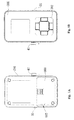
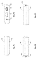
- Figs. 1A to 1F , Fig. 2 and Fig. 3 show a negative pressure generator according to the first embodiment of the present invention.
- Fig. 1A through Fig. 1F illustrates various aspects of the appearance of the negative pressure generator according to the first embodiment of the present invention, in which Fig. 1A is a top view, Fig. 1B is a bottom view, Fig. 1 C is a front view relative to the bottom view of Fig. 1 B , Fig. 1D is a rear view relative to the bottom view of Fig. 1B , Fig. 1E is a left side view relative to the bottom view of Fig. 1B , and Fig. 1F is a right side view relative to the bottom view of Fig. 1B .
- Fig. 1A is a top view
- Fig. 1B is a bottom view
- Fig. 1 C is a front view relative to the bottom view of Fig. 1 B
- Fig. 1D is a rear view relative to the bottom view
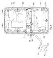
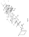
- FIG. 2 is a perspective exploded view of the negative pressure generator according to the first embodiment of the present invention.
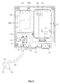
- Fig. 3 is a diagram showing an arrangement relationship among the components of a bottom housing module of the negative pressure generator connected with an oral interface device according to the first embodiment of the present invention.
- the negative pressure generator is capable of providing a vacuum source to various oral interface devices for treating OSA.
- the negative pressure generator mainly comprises a vacuum pump module 10, a control module 20, a bottom housing module 200, a top housing module 300, a front cover module 500 and a power supply source.
- the power supply source can supply power by connecting to an external power source via an external power source connection port 35.
- the power supply source is a battery pack (not shown) installed in the battery holder 202 formed in a lower compartment of the bottom housing module 200.
- a battery protective cover 600 is arranged at the lower portion of the back of the bottom housing module 200 to cover the battery holder 202.
- the battery protective cover 600 defines a plurality of exhaust vents 602 at one side thereof close to the external power source connection port 35.
- the vacuum pump module 10 comprises a vacuum pump 100, a flexible intake tube 101, a flexible exhaust tube 102 and a soundproofing module 103.
- the vacuum pump 100 has an intake end 1001 communicating with one open end of the flexible intake tube 101 and an exhaust end 1002 communicating with one open end of the flexible exhaust tube 102.
- the soundproofing module 103 encloses the vacuum pump 100; the flexible intake tube 101 extends from the intake end 1001 to the exterior of the soundproofing module 103; the flexible exhaust tube 102 extends from the exhaust end 1002 and winds around the exterior of the soundproofing module 103 in a multiple loop configuration; one open end of the flexible exhaust tube 102 opposite to the open end thereof facing the exhaust end 1002 passes through a hole 203 (see Fig. 3 ) defined at the side of the bottom housing module 200 close to the external power source connection port 35 to communicate with the exhaust vent 602 defined on the battery protective cover 600 to discharge; via the exhaust vent 602, air sucked by the vacuum pump 100 to the ambient environment.
- the soundproofing module 103 can insulate the ambient environment against noise and vibration generated when the vacuum pump 100 is in operation.
- the soundproofing module 103 can be made of a porous sound absorbing material, such as a sound absorbing foam, e.g., polyurethane (PU) foam, polyethylene (PE) foam, etc.
- the soundproofing module 103 can be made of a material selected from a group consisting of silicone, plastic (e.g., PMMA, PC, PP), EVA and PU.
- the soundproofing module 103 can comprise a first cover member 1030, an intermediate housing 1032 having a hollow chamber 1033 for accommodating the vacuum pump 100 (see Fig.
- the flexible exhaust tube 102 winds around the exterior of the soundproofing module 103 in a multiple loop configuration.
- the length of the flexible exhaust tube 102 can be extended without increasing the size of the vacuum pump module 10, thereby reducing noise generated at the exhaust end 1002 of the vacuum pump 100 when the vacuum pump 100 is in operation.
- the flexible intake tube 101 and the flexible exhaust tube 102 can be made of a material selected from a group consisting of silicone, plastic (e.g., PMMA, PC, PP), EVA and PU.
- the flexible intake tube 101 and/or the flexible exhaust tube 102 of the present invention can adopt other configurations to extend the length(s) thereof without increasing the size of the vacuum pump module 10, thereby reducing noise generated at the intake end 1001 and/or the exhaust end 1002 when the vacuum pump 100 is in operation.
- Fig. 5 shows a first variation of the vacuum pump module of the present invention.
- the vacuum pump module comprises a vacuum pump 100 having an intake end 1001 and an exhaust end 1002, a soundproofing module (1030a, 1032a, 1034a), a flexible multiply bent intake tube 101a and a flexible multiply bent exhaust tube 102a.
- the soundproofing module comprises a first cover member 1030a, an intermediate housing 1032a having a hollow chamber for accommodating the vacuum pump 100, and a second cover member 1034a.
- the flexible intake tube 101a is disposed inside the second cover member 1034a with one open end thereof extending out of the second cover member 1034a to communicate with the intake end 1001 of the vacuum pump 100 and the other open end thereof extending out of the second cover member 1034a.
- the flexible exhaust tube 102a is disposed inside the first cover member 1030a with one open end thereof extending out of the first cover member 1030a to communicate with the exhaust end 1002 of the vacuum pump 100 and the other open end thereof extending out of the first cover member 1030a.
- the flexible intake tube 101a and the second cover member 1034a can be formed integrally through injection molding.
- the flexible exhaust tube 102a and the first cover member 1030a can be formed integrally through injection molding.
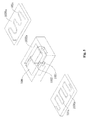
- Fig. 6 shows a second variation of the vacuum pump module of the present invention.
- the vacuum pump module is different from the vacuum pump module 10 of the first embodiment in that the flexible exhaust tube 102b comprises a plurality of flexible tubes connected in parallel and clustered at the open ends 1022b and 1024b.
- the open end 1022b communicates with the exhaust end 1002 of the vacuum pump 100.
- the open end 1024b communicates with the ambient environment.
- the vacuum pump 100 is disposed in the hollow chamber 1033 of the intermediate housing 1032, and the flexible exhaust tube 102b comprising a plurality of flexible tubes connected in parallel winds around an exterior of the intermediate housing 1032.
- the intake end 1001 of the vacuum pump 100 communicates with a flexible intake tube 101b.
- Fig. 7 shows another variation of the flexible intake tube 101 and the flexible exhaust tube 102 of the present invention.
- a plurality of multiply bent tubes connected in parallel serve as the flexible intake tube 101c and the flexible exhaust tube 102c, which are disposed inside the second cover member 1034c and the first cover member 1030c of the soundproofing module, respectively.
- the flexible intake tube 101c and the second cover member 1034c can be integrally formed through injection molding, and the flexible exhaust tube 102c and the first cover member 1030c can be formed integrally through injection molding.
- the rest of the components of the vacuum pump module are the same as the corresponding components of the variation shown in Fig. 5 , thus the descriptions thereof are not presented.
- Fig. 8 shows another variation of the flexible intake tube 101 and the flexible exhaust tube 102 of the present invention.
- the flexible intake tube 101d and the flexible exhaust tube 102d are arranged in a grating-shaped loop configuration, and a porous material 1035 is filled in the flexible intake tube 101d and the flexible exhaust tube 102d.
- the flexible intake tube 101d is disposed on a surface of the second cover member 1034d of the soundproofing module opposite to the surface thereof facing the vacuum pump 100, and the flexible exhaust tube 102d is disposed on a surface of the first cover member 1030d of the soundproofing module opposite to the surface thereof facing the vacuum pump 100.
- the rest of the components of the vacuum pump module are the same as the corresponding components of the variation shown in Fig. 5 , thus the descriptions thereof are not presented.
- an ordinarily skilled person in the art can easily infer the complete structure of the vacuum pump module adopting the configuration of the flexible intake tube and the flexible exhaust tube illustrated in Fig. 8 from the vacuum pump module shown in Fig. 5 .
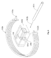
- the negative pressure generator of the present invention further comprises a tri-way connector module 40 and a check valve module 50.
- the tri-way connector module 40 one port thereof is connected to the check valve module 50, another port thereof communicates with a pressure relief valve 60, and another port thereof can communicate with an oral interface device 70 for generating negative pressure in the oral cavity.
- the oral interface device 70 has an air conduit 700 whose one open end 702 communicates with a corresponding port of the tri-way connector module 40 and whose the other open end 704 is placed in a user's oral cavity.
- the oral interface device 70 further comprises an oral interface 710 placed in the user's oral cavity to secure the open end 704 of the air conduit 700 in the oral cavity.
- the present invention can use the oral interface device disclosed in the PCT International Patent Application No. PCT/US14/11129 filed on January 10, 2014 and incorporated herein by reference.
- the other open end of the check valve module 50 communicates with one open end of the flexible intake tube 101 opposite to the open end thereof facing the intake end 1001 of the vacuum pump.
- the air conduit 700 can communicate with the tri-way connector module 40 via an adaptor 42.
- the negative pressure generator of the present invention provides a vacuum source to the oral interface device 70, the air conduit 700, the flexible intake tube 101, the vacuum pump 100 and the flexible exhaust tube 102 constitute a negative pressure path so as to favorably create a negative pressure environment in the user's oral cavity.
- the check valve module 50 can direct the flow of air in the negative pressure path from the air conduit 700 to the flexible exhaust tube 102.
- one open end of the flexible exhaust tube 102 opposite to the open end thereof facing the exhaust end 1002 or the vacuum pump can communicate with a saliva container (not shown).
- the negative pressure generator can include a pressure sensor (not shown) communicating with an air flow channel 52 of the check valve module 50 so as to measure a pressure value of the negative pressure path.
- the pressure sensor (not shown) can be disposed in the control module 20.
- the power supply source of the negative pressure generator can be a battery pack installed in the battery holder 202 so that the negative pressure generator can be favorably manufactured as a portable device for the better convenience of users.
- the power supply source can be an external power source.
- the negative pressure generator is connected to an external power source through the external power source connection port 35.
- the power supply source is electrically connected to the control module 20 through which the magnitude of the power supplied to the vacuum pump 100 can be controlled, thereby reaching the desired negative pressure value in the user's oral cavity.
- the control module 20 can adjust the magnitude of the power supplied to the vacuum pump 100 according to the negative pressure value detected by the pressure sensor. As shown in Fig.
- a pair of extension portions 1034e is respectively disposed at two opposing sides of the second cover member 1034 of the soundproofing module 103 of the vacuum pump module 10. After the pair of extension portions 1034e have been bent upwards (as shown in the dotted lines in Fig.
- the vacuum pump module 10 can be installed in the corresponding compartment of the bottom housing module 200 so that the pair of bent extension portions 1034e can secure the flexible intake tube 101 and the exhaust tube 102 winding around the exterior of the soundproofing module 103.
- the tri-way connector module 40 can be secured to the bottom housing module 200 via a threaded member.
- the external power source connection port 35 can be defined at an outer side of the bottom housing module 200 while the adaptor 42 that communicates with the air conduit 700 of the oral interface device 70 can be disposed at another outer side opposite thereto. The manner in which the components of the negative pressure generator of the present invention are assembled is shown in Fig. 2 .
- the control module 20 is disposed between the top housing module 300 and the bottom housing module 200 which is shown partially assembled in Fig. 3 .
- the control module 20 is secured over the bottom housing module 200 via a threaded member.
- the top housing module 300 has a slot 301 defined at a lower portion thereof.
- a deformable member 30 is disposed in the slot 301, and a cover panel 302 is inlaid above the slot 301 to press against the deformable member 30.
- the top surface of the cover panel 302 are provided with a plurality of buttons 3020 corresponding to different functions executed through the control module 20.
- the negative pressure generator further comprises a protective cover 400 covering over the top housing module 300.
- the protective cover 400 has a cavity 402 defined at a lower portion thereof.
- the buttons 3020 of the cover panel 302 are exposed alter being engaged with the cavity 402 so that the user can press any of them to execute the desired function correspondingly.
- the front cover module 500 of the negative pressure generator of the present invention is disposed at the front sides of the bottom housing module 200 and the top housing module 300.
- the front cover module 500 comprises a front cover 502, a sliding bump 504, a position limiting bump 506 and a positioning threaded member 508.
- the front cover 502 has an accommodation hole 5020, a pair of first engaging members 5022 and a pair of second engaging members 5024.
- the sliding bump 504 passes through the accommodation hole 5020 and abuts against a slanted surface of the position limiting bump 506.
- the positioning threaded member 508 is threadedly engaged with the front cover 502 at a proper position and abuts against the position limiting bump 506 to position the sliding bump 504 and the position limiting bump 506.
- the pair of first engaging members 5022 are engaged with a pair of corresponding engaging slots defined on the bottom housing module 200
- the pair of second engaging members 5024 are engaged with a pair of corresponding engaging slots defined on the top housing module 300.
- the present invention also discloses the assembling of the bottom housing module 200 and the top housing module 300 through threaded engagement by using, for example, various threaded members and the corresponding threaded holes illustrated in Fig. 2 .
- Fig. 9 , Fig. 10 and Fig. 11 show a negative pressure generator according to the second embodiment of the present invention.
- Fig.9A through Fig. 9F illustrates various aspects of the appearance of the negative pressure generator according to the second embodiment of the present invention, in which Fig. 9A is a top view, Fig. 9B is a bottom view, Fig. 9C is a front view relative to the bottom view of Fig. 9B , Fig. 9D is a rear view relative to the bottom view of Fig. 9B , Fig. 9E is a left side view relative to the bottom view of Fig. 9B , and Fig. 9F is a right side view relative to the bottom view of Fig. 9B .
- Fig. 9A is a top view
- Fig. 9B is a bottom view
- Fig. 9C is a front view relative to the bottom view of Fig. 9B
- Fig. 9D is a rear view relative to the bottom view of Fig. 9
- the negative pressure generator mainly comprises a vacuum pump module 90, a control module 91, a bottom housing module 95, a top housing module 96 and a power supply source.
- the power supply source is the battery pack (not shown) installed in a battery holder 952 of the bottom housing module 95.
- a battery holder cover 953 is provided with engaging blocks at two opposing sides thereof to engage with the corresponding engaging recesses of the bottom housing module 95 so as to cover the battery holder 952 and to serve as a base of the battery holder. The user can simply lift the battery holder cover 953 to replace the battery pack.
- the vacuum pump module 90 is disposed in a compartment 950 of the bottom housing module 95 besides the battery holder 952.
- the vacuum pump module 90 comprises a vacuum pump 900, a flexible intake tube 901, a flexible exhaust tube 902 and a soundproofing module 903.
- the vacuum pump 900 has an intake end 9001 communicating with one open end of the flexible intake tube 901 and an exhaust end 9002 communicating with one open end of the flexible exhaust tube 902.
- the soundproofing module 903 encloses the vacuum pump 900, the flexible intake tube 901 extends from the intake end 9001 to an exterior of the soundproofing module 903, the flexible exhaust tube 902 extends from the exhaust end 9002 and winds around the exterior of the soundproofing module 903 in a multiple loop configuration.
- the soundproofing module 903 can insulate the ambient environment against noise and vibration generated when the vacuum pump 900 is in operation.
- the soundproofing module 903 is made of a material selected from the same group of materials for the soundproofing module 103 in the first embodiment.
- the soundproofing module 903 can comprise a first cover member 9030, an intermediate housing 9032 and a second cover member 9034, wherein the intermediate housing 9032 has a hollow chamber 9033 for accommodating the vacuum pump 900 (see Fig. 12F ).
- the flexible exhaust tube 902 winds around the exterior of the soundproofing module 903 in a multiple loop configuration. With such a multiple loop configuration, the length of the flexible exhaust tube 902 can be extended without increasing the size of the vacuum pump module 90, thereby reducing noise generated at the exhaust end 9002 of the vacuum pump 900 when the vacuum pump 900 is in operation.
- the flexible intake tube 901 and the flexible exhaust tube 902 are made of any material selected from the same group of materials used in the first embodiment.
- the negative pressure generator of the second embodiment of the present invention further comprises a check valve module 92, a tri-way connector module 93 and an adaptor 94.
- the check valve module 92 and the tri-way connector module 93 are disposed at the lower portion of the compartment 950 of the bottom housing module 95.
- One end of the check valve module 92 communicates with one open end of the flexible intake tube 901 opposite to the open end thereof facing the intake end 9001, and the other end of the check valve module 92 communicates with one port of the tri-way connector module 93.
- the adaptor 94 communicates with another port 932 of the tri-way connector module 93 and passes through the respective one sides of the top housing module 96 and the bottom housing module 95 (as shown in Fig. 9D ).
- One open end of the air conduit 700 of the oral interface device 70 communicates with the adaptor 94 through which the air conduit 700 communicates with the flexible intake tube 901.
- the negative pressure generator of the present invention provides a vacuum source to the oral interface device 70
- the air conduit 700, the flexible intake tube 901, the vacuum pump 900 and the flexible exhaust tube 902 constitute a negative pressure path so as to create a negative pressure environment in the user's oral cavity.
- the check valve module 92 can direct air in the negative pressure path to flow from the air conduit 700 to the flexible exhaust tube 902.
- An indentation 955 is defined at one top corner of the compartment 950 of the bottom housing module 95 to receive an exhaust filter component 954 comprising a cotton filter pad 954a and an exhaust vent cover 954b.
- the exhaust vent cover 954b engages with the indentation 955 to secure the cotton filter pad 954a inside the indentation 955.
- one open end 9022 of the flexible exhaust tube 902 opposite to the open end thereof facing the exhaust end 9002 communicates with the cotton filter pad 954a inside the indentation 955 and discharges air sucked by the vacuum pump 900 to the ambient environment via the cotton filter pad 954a and the exhaust vent cover 954b.
- another port of the tri-way connector module 93 can be connected to a pressure sensor (not shown) disposed in the control module 91 so as to detect a negative pressure value of the negative pressure path.
- the power supply source is electrically connected to the control module 91 through which the magnitude of the power supplied to the vacuum pump 900 can be controlled so as to favorably reach a desired negative pressure value in the user's oral cavity.
- the control module 91 can adjust the magnitude of the power supplied to the vacuum pump 900 according to the negative pressure value detected by the pressure sensor.
- the negative pressure generator further comprises a power switch 98 and a communication connection port 99.
- the power switch 98 is electrically connected to the control module 91, and the user can press the power switch 98 to turn on or turn off the power supply via the control module 91.
- the communication connection port 99 is electrically connected to the control module 91, and the user can select the operation mode of the vacuum pump 900 through the comnunication connection port 99.
- the negative pressure generator can further comprise a warning device 97 electrically connected to the control module 91 and passing through the outer surface of the top housing module 96 so that the state presented on the warning device 97 can be observed easily.
- the warning device 97 can call the attention of the user or another person near the user to the usage condition of the negative pressure generator.
- the warning device 97 can be embodied by an LED light set comprising a plurality of LED indicators of different colors.
- the control module 91 can light up an LED indicator of a certain color to call the attention of the user or another person near the user to the likely occurrence of an air leakage or occlusion of the air conduit of the negative pressure generator.
- the control module 91 can light up another LED indicator of a different color to indicate that the negative pressure generator functions normally.
Landscapes
- Health & Medical Sciences (AREA)
- Pulmonology (AREA)
- Animal Behavior & Ethology (AREA)
- General Health & Medical Sciences (AREA)
- Veterinary Medicine (AREA)
- Engineering & Computer Science (AREA)
- Biomedical Technology (AREA)
- Heart & Thoracic Surgery (AREA)
- Public Health (AREA)
- Life Sciences & Earth Sciences (AREA)
- Otolaryngology (AREA)
- Emergency Medicine (AREA)
- Anesthesiology (AREA)
- Hematology (AREA)
- Nursing (AREA)
- Vascular Medicine (AREA)
- Orthopedic Medicine & Surgery (AREA)
- Reciprocating Pumps (AREA)
- Orthopedics, Nursing, And Contraception (AREA)
- External Artificial Organs (AREA)
- Respiratory Apparatuses And Protective Means (AREA)
- Compressors, Vaccum Pumps And Other Relevant Systems (AREA)
Applications Claiming Priority (1)
| Application Number | Priority Date | Filing Date | Title |
|---|---|---|---|
| PCT/CN2014/093160 WO2016086418A1 (fr) | 2014-12-05 | 2014-12-05 | Dispositif de génération de pression négative et son application |
Publications (3)
| Publication Number | Publication Date |
|---|---|
| EP3095421A1 true EP3095421A1 (fr) | 2016-11-23 |
| EP3095421A4 EP3095421A4 (fr) | 2017-01-18 |
| EP3095421B1 EP3095421B1 (fr) | 2018-08-08 |
Family
ID=56090859
Family Applications (1)
| Application Number | Title | Priority Date | Filing Date |
|---|---|---|---|
| EP14907504.6A Active EP3095421B1 (fr) | 2014-12-05 | 2014-12-05 | Dispositif de génération de pression négative et son application |
Country Status (5)
| Country | Link |
|---|---|
| US (1) | US10159595B2 (fr) |
| EP (1) | EP3095421B1 (fr) |
| JP (1) | JP6346997B2 (fr) |
| CN (1) | CN106170272B (fr) |
| WO (1) | WO2016086418A1 (fr) |
Families Citing this family (9)
| Publication number | Priority date | Publication date | Assignee | Title |
|---|---|---|---|---|
| US10806877B2 (en) * | 2015-03-24 | 2020-10-20 | Micomme Medical Technology Development Co., Ltd. | Portable breathing machine |
| GB201718752D0 (en) * | 2017-11-13 | 2017-12-27 | Edwards Ltd | Vacuum and abatement systems |
| CN109011072A (zh) * | 2018-06-26 | 2018-12-18 | 北京大学深圳医院 | 麻醉气管固定装置 |
| AU2020410910B2 (en) * | 2019-12-24 | 2025-12-04 | ResMed Pty Ltd | Respiratory therapy apparatus with removable connectivity module and components thereof |
| US11197969B2 (en) * | 2020-04-27 | 2021-12-14 | EFK Consulting, INC | Miniature air filtration assembly for a medical field |
| EP4154851A4 (fr) | 2020-05-21 | 2024-05-29 | Good News Medical Co., Ltd. | Dispositif d'atténuation d'obstruction respiratoire durant le sommeil |
| EP3915601A1 (fr) * | 2020-05-25 | 2021-12-01 | Mölnlycke Health Care AB | Dispositif mobile de traitement de plaies par pression négative avec réduction du bruit de pompe |
| US12508382B2 (en) | 2021-06-18 | 2025-12-30 | University Of Rochester | Myofunctional training with negative airway pressure for obstructive sleep apnea |
| USD1088233S1 (en) * | 2021-07-14 | 2025-08-12 | Somnics, Inc. | Silencer housing for sleep breathing-treatment device |
Family Cites Families (24)
| Publication number | Priority date | Publication date | Assignee | Title |
|---|---|---|---|---|
| US5957133A (en) * | 1997-07-21 | 1999-09-28 | Hart; William T. | Oral appliance with negative air supply for reducing sleep apnea and snoring |
| AUPP015197A0 (en) * | 1997-11-03 | 1997-11-27 | Resmed Limited | A muffler for an apparatus for supplying breathable gas |
| US8517012B2 (en) * | 2001-12-10 | 2013-08-27 | Resmed Limited | Multiple stage blowers and volutes therefor |
| CN100591380C (zh) * | 2003-06-10 | 2010-02-24 | 雷斯梅德有限公司 | 多级吹风机及其外壳 |
| EP1684836A1 (fr) * | 2003-11-05 | 2006-08-02 | MAP Medizin-Technologie GmbH | Dispositif servant a conduire un gaz a respirer, et structure de guidage d'air placee dans ce dispositif |
| DE102004002031B4 (de) * | 2004-01-14 | 2006-05-24 | Seleon Gmbh | Pumpemodul und Beatmungsgerät |
| US7398855B2 (en) | 2004-05-14 | 2008-07-15 | Emerson Climate Technologies, Inc. | Compressor sound attenuation enclosure |
| DE102006024839A1 (de) * | 2006-05-24 | 2007-11-29 | Seleon Gmbh | Fördereinheit und Förderverfahren |
| ES2358134T3 (es) * | 2006-05-30 | 2011-05-05 | Industrial Technology Research Institute | Aparato para tratar apnea del sueño obstructiva usando presión oral negativa en un paciente. |
| US7918222B2 (en) * | 2006-05-30 | 2011-04-05 | Industrial Technology Research Institute | Method and apparatus for treating obstructive sleep apnea by using negative oral pressure to a patient |
| WO2008028247A1 (fr) | 2006-09-07 | 2008-03-13 | Resmed Ltd | Masque et système générateur de flux |
| JP5468747B2 (ja) * | 2007-06-05 | 2014-04-09 | レスメド・モーター・テクノロジーズ・インコーポレーテッド | 軸受管を有するブロワ |
| GB0712739D0 (en) * | 2007-07-02 | 2007-08-08 | Smith & Nephew | Apparatus |
| US8122890B2 (en) * | 2007-11-13 | 2012-02-28 | Apnicure, Inc. | Methods and systems for saliva management with an oral device |
| CN201200652Y (zh) | 2008-03-31 | 2009-03-04 | 天津市同业科技发展有限公司 | 一种便携式负压吸引器 |
| GB2465364B (en) * | 2008-11-13 | 2011-03-30 | Thermo Fisher Scient | Enclosure,assembly and method for reducing noise from a pump |
| WO2011011524A2 (fr) * | 2009-07-21 | 2011-01-27 | Deka Products Limited Partnership | Atténuation acoustique pour dispositif mécanique |
| TWI499408B (zh) | 2009-09-28 | 2015-09-11 | Somnics Inc Taiwan | 負壓式口部裝置 |
| US20120053542A1 (en) * | 2010-08-31 | 2012-03-01 | Apex Medical Corp. | Actuator for a negative pressure wound therapy system |
| GB2485417B (en) | 2010-11-15 | 2018-07-18 | Oellgaard Jensen Frede | Reversible proportional fluid control valve |
| DE102011055782A1 (de) | 2011-11-28 | 2013-05-29 | Birgit Riesinger | Wundpflegevorrichtung zur behandlung von wunden mittels atmosphärischem unterdruck |
| US10149782B2 (en) | 2012-08-03 | 2018-12-11 | Somnics, Inc. | Oral interface and method using the same |
| WO2014145869A1 (fr) * | 2013-03-15 | 2014-09-18 | Human Design Medical, Llc | Systèmes et procédés permettant de produire une pression positive à faible niveau de bruit pour les voies respiratoires |
| CN203189231U (zh) | 2013-04-28 | 2013-09-11 | 苏州盟通利机电设备有限公司 | 真空泵抽气装置 |
-
2014
- 2014-12-05 JP JP2017529724A patent/JP6346997B2/ja active Active
- 2014-12-05 CN CN201480042066.5A patent/CN106170272B/zh active Active
- 2014-12-05 WO PCT/CN2014/093160 patent/WO2016086418A1/fr not_active Ceased
- 2014-12-05 US US15/308,048 patent/US10159595B2/en active Active
- 2014-12-05 EP EP14907504.6A patent/EP3095421B1/fr active Active
Also Published As
| Publication number | Publication date |
|---|---|
| JP2017536204A (ja) | 2017-12-07 |
| WO2016086418A1 (fr) | 2016-06-09 |
| CN106170272A (zh) | 2016-11-30 |
| CN106170272B (zh) | 2018-06-12 |
| US10159595B2 (en) | 2018-12-25 |
| EP3095421A4 (fr) | 2017-01-18 |
| JP6346997B2 (ja) | 2018-06-20 |
| EP3095421B1 (fr) | 2018-08-08 |
| US20170049606A1 (en) | 2017-02-23 |
Similar Documents
| Publication | Publication Date | Title |
|---|---|---|
| US10159595B2 (en) | Negative pressure generating device and application thereof | |
| TWI829798B (zh) | 霧劑輸送裝置 | |
| JP5616359B2 (ja) | 被検者の気道をサポートするためのシステム及び呼吸器具 | |
| EP3432956B1 (fr) | Système électronique de fourniture de vapeur | |
| JP5616358B2 (ja) | 対象者の気道を支持するためのシステム及び呼吸用機器 | |
| CA2753378C (fr) | Appareil respiratoire pour inhalation de gaz, muni d'un humidificateur | |
| CN102083492B (zh) | 用于呼吸系统的加湿器 | |
| CN102271631B (zh) | 用于支撑对象气道的系统和呼吸器具 | |
| US9216266B2 (en) | System and respiration appliance for supporting the airway of a subject | |
| US20130056010A1 (en) | Autonomous positive airway pressure system | |
| US9302068B2 (en) | Humidity control in a pressure support system | |
| WO2007139531A1 (fr) | masque de ventilation hybride avec interfAce nasale et procÉdÉ DE CONFIGURATION D'un tel masque | |
| EP4034209B1 (fr) | Interface patient avec oxymètre | |
| WO2012028971A1 (fr) | Accessoire de soupape pour faciliter la parole pendant une thérapie respiratoire non invasive | |
| US20070000493A1 (en) | Apparatus for maintaining airway patency | |
| KR20130001750A (ko) | 금연보조기의 수동 주입 노즐형 카트리지 | |
| US20130239965A1 (en) | Humidification system with signal transmission optimization | |
| EP3758184A1 (fr) | Dispositif de chargement et kit de substitution du tabac | |
| TWI569827B (zh) | 負壓產生裝置及其應用 | |
| KR101812518B1 (ko) | 공기공급기능을 구비한 마스크 | |
| JP3252534U (ja) | 水素吸入具 | |
| CN216536610U (zh) | 对寒冷干燥空气加热加湿的装置 | |
| CN110367601A (zh) | 易装拆卡扣式的壳体及一次性电子烟 |
Legal Events
| Date | Code | Title | Description |
|---|---|---|---|
| PUAI | Public reference made under article 153(3) epc to a published international application that has entered the european phase |
Free format text: ORIGINAL CODE: 0009012 |
|
| 17P | Request for examination filed |
Effective date: 20160816 |
|
| AK | Designated contracting states |
Kind code of ref document: A1 Designated state(s): AL AT BE BG CH CY CZ DE DK EE ES FI FR GB GR HR HU IE IS IT LI LT LU LV MC MK MT NL NO PL PT RO RS SE SI SK SM TR |
|
| AX | Request for extension of the european patent |
Extension state: BA ME |
|
| A4 | Supplementary search report drawn up and despatched |
Effective date: 20161220 |
|
| RIC1 | Information provided on ipc code assigned before grant |
Ipc: A61F 5/56 20060101AFI20161214BHEP Ipc: A61M 16/00 20060101ALI20161214BHEP |
|
| 17Q | First examination report despatched |
Effective date: 20170904 |
|
| DAX | Request for extension of the european patent (deleted) | ||
| GRAP | Despatch of communication of intention to grant a patent |
Free format text: ORIGINAL CODE: EPIDOSNIGR1 |
|
| INTG | Intention to grant announced |
Effective date: 20180423 |
|
| GRAS | Grant fee paid |
Free format text: ORIGINAL CODE: EPIDOSNIGR3 |
|
| GRAA | (expected) grant |
Free format text: ORIGINAL CODE: 0009210 |
|
| AK | Designated contracting states |
Kind code of ref document: B1 Designated state(s): AL AT BE BG CH CY CZ DE DK EE ES FI FR GB GR HR HU IE IS IT LI LT LU LV MC MK MT NL NO PL PT RO RS SE SI SK SM TR |
|
| REG | Reference to a national code |
Ref country code: GB Ref legal event code: FG4D |
|
| REG | Reference to a national code |
Ref country code: CH Ref legal event code: EP Ref country code: AT Ref legal event code: REF Ref document number: 1026131 Country of ref document: AT Kind code of ref document: T Effective date: 20180815 |
|
| REG | Reference to a national code |
Ref country code: FR Ref legal event code: PLFP Year of fee payment: 5 |
|
| REG | Reference to a national code |
Ref country code: IE Ref legal event code: FG4D |
|
| REG | Reference to a national code |
Ref country code: DE Ref legal event code: R096 Ref document number: 602014030273 Country of ref document: DE |
|
| REG | Reference to a national code |
Ref country code: NL Ref legal event code: MP Effective date: 20180808 |
|
| REG | Reference to a national code |
Ref country code: LT Ref legal event code: MG4D |
|
| REG | Reference to a national code |
Ref country code: AT Ref legal event code: MK05 Ref document number: 1026131 Country of ref document: AT Kind code of ref document: T Effective date: 20180808 |
|
| PG25 | Lapsed in a contracting state [announced via postgrant information from national office to epo] |
Ref country code: PL Free format text: LAPSE BECAUSE OF FAILURE TO SUBMIT A TRANSLATION OF THE DESCRIPTION OR TO PAY THE FEE WITHIN THE PRESCRIBED TIME-LIMIT Effective date: 20180808 Ref country code: RS Free format text: LAPSE BECAUSE OF FAILURE TO SUBMIT A TRANSLATION OF THE DESCRIPTION OR TO PAY THE FEE WITHIN THE PRESCRIBED TIME-LIMIT Effective date: 20180808 Ref country code: IS Free format text: LAPSE BECAUSE OF FAILURE TO SUBMIT A TRANSLATION OF THE DESCRIPTION OR TO PAY THE FEE WITHIN THE PRESCRIBED TIME-LIMIT Effective date: 20181208 Ref country code: SE Free format text: LAPSE BECAUSE OF FAILURE TO SUBMIT A TRANSLATION OF THE DESCRIPTION OR TO PAY THE FEE WITHIN THE PRESCRIBED TIME-LIMIT Effective date: 20180808 Ref country code: FI Free format text: LAPSE BECAUSE OF FAILURE TO SUBMIT A TRANSLATION OF THE DESCRIPTION OR TO PAY THE FEE WITHIN THE PRESCRIBED TIME-LIMIT Effective date: 20180808 Ref country code: GR Free format text: LAPSE BECAUSE OF FAILURE TO SUBMIT A TRANSLATION OF THE DESCRIPTION OR TO PAY THE FEE WITHIN THE PRESCRIBED TIME-LIMIT Effective date: 20181109 Ref country code: NO Free format text: LAPSE BECAUSE OF FAILURE TO SUBMIT A TRANSLATION OF THE DESCRIPTION OR TO PAY THE FEE WITHIN THE PRESCRIBED TIME-LIMIT Effective date: 20181108 Ref country code: AT Free format text: LAPSE BECAUSE OF FAILURE TO SUBMIT A TRANSLATION OF THE DESCRIPTION OR TO PAY THE FEE WITHIN THE PRESCRIBED TIME-LIMIT Effective date: 20180808 Ref country code: NL Free format text: LAPSE BECAUSE OF FAILURE TO SUBMIT A TRANSLATION OF THE DESCRIPTION OR TO PAY THE FEE WITHIN THE PRESCRIBED TIME-LIMIT Effective date: 20180808 Ref country code: LT Free format text: LAPSE BECAUSE OF FAILURE TO SUBMIT A TRANSLATION OF THE DESCRIPTION OR TO PAY THE FEE WITHIN THE PRESCRIBED TIME-LIMIT Effective date: 20180808 Ref country code: BG Free format text: LAPSE BECAUSE OF FAILURE TO SUBMIT A TRANSLATION OF THE DESCRIPTION OR TO PAY THE FEE WITHIN THE PRESCRIBED TIME-LIMIT Effective date: 20181108 |
|
| PG25 | Lapsed in a contracting state [announced via postgrant information from national office to epo] |
Ref country code: HR Free format text: LAPSE BECAUSE OF FAILURE TO SUBMIT A TRANSLATION OF THE DESCRIPTION OR TO PAY THE FEE WITHIN THE PRESCRIBED TIME-LIMIT Effective date: 20180808 Ref country code: LV Free format text: LAPSE BECAUSE OF FAILURE TO SUBMIT A TRANSLATION OF THE DESCRIPTION OR TO PAY THE FEE WITHIN THE PRESCRIBED TIME-LIMIT Effective date: 20180808 Ref country code: AL Free format text: LAPSE BECAUSE OF FAILURE TO SUBMIT A TRANSLATION OF THE DESCRIPTION OR TO PAY THE FEE WITHIN THE PRESCRIBED TIME-LIMIT Effective date: 20180808 |
|
| PG25 | Lapsed in a contracting state [announced via postgrant information from national office to epo] |
Ref country code: RO Free format text: LAPSE BECAUSE OF FAILURE TO SUBMIT A TRANSLATION OF THE DESCRIPTION OR TO PAY THE FEE WITHIN THE PRESCRIBED TIME-LIMIT Effective date: 20180808 Ref country code: CZ Free format text: LAPSE BECAUSE OF FAILURE TO SUBMIT A TRANSLATION OF THE DESCRIPTION OR TO PAY THE FEE WITHIN THE PRESCRIBED TIME-LIMIT Effective date: 20180808 Ref country code: ES Free format text: LAPSE BECAUSE OF FAILURE TO SUBMIT A TRANSLATION OF THE DESCRIPTION OR TO PAY THE FEE WITHIN THE PRESCRIBED TIME-LIMIT Effective date: 20180808 Ref country code: EE Free format text: LAPSE BECAUSE OF FAILURE TO SUBMIT A TRANSLATION OF THE DESCRIPTION OR TO PAY THE FEE WITHIN THE PRESCRIBED TIME-LIMIT Effective date: 20180808 Ref country code: IT Free format text: LAPSE BECAUSE OF FAILURE TO SUBMIT A TRANSLATION OF THE DESCRIPTION OR TO PAY THE FEE WITHIN THE PRESCRIBED TIME-LIMIT Effective date: 20180808 |
|
| REG | Reference to a national code |
Ref country code: DE Ref legal event code: R097 Ref document number: 602014030273 Country of ref document: DE |
|
| PG25 | Lapsed in a contracting state [announced via postgrant information from national office to epo] |
Ref country code: SM Free format text: LAPSE BECAUSE OF FAILURE TO SUBMIT A TRANSLATION OF THE DESCRIPTION OR TO PAY THE FEE WITHIN THE PRESCRIBED TIME-LIMIT Effective date: 20180808 Ref country code: DK Free format text: LAPSE BECAUSE OF FAILURE TO SUBMIT A TRANSLATION OF THE DESCRIPTION OR TO PAY THE FEE WITHIN THE PRESCRIBED TIME-LIMIT Effective date: 20180808 Ref country code: SK Free format text: LAPSE BECAUSE OF FAILURE TO SUBMIT A TRANSLATION OF THE DESCRIPTION OR TO PAY THE FEE WITHIN THE PRESCRIBED TIME-LIMIT Effective date: 20180808 |
|
| PLBE | No opposition filed within time limit |
Free format text: ORIGINAL CODE: 0009261 |
|
| STAA | Information on the status of an ep patent application or granted ep patent |
Free format text: STATUS: NO OPPOSITION FILED WITHIN TIME LIMIT |
|
| 26N | No opposition filed |
Effective date: 20190509 |
|
| REG | Reference to a national code |
Ref country code: CH Ref legal event code: PL |
|
| PG25 | Lapsed in a contracting state [announced via postgrant information from national office to epo] |
Ref country code: LU Free format text: LAPSE BECAUSE OF NON-PAYMENT OF DUE FEES Effective date: 20181205 Ref country code: SI Free format text: LAPSE BECAUSE OF FAILURE TO SUBMIT A TRANSLATION OF THE DESCRIPTION OR TO PAY THE FEE WITHIN THE PRESCRIBED TIME-LIMIT Effective date: 20180808 Ref country code: MC Free format text: LAPSE BECAUSE OF FAILURE TO SUBMIT A TRANSLATION OF THE DESCRIPTION OR TO PAY THE FEE WITHIN THE PRESCRIBED TIME-LIMIT Effective date: 20180808 |
|
| REG | Reference to a national code |
Ref country code: IE Ref legal event code: MM4A |
|
| REG | Reference to a national code |
Ref country code: BE Ref legal event code: MM Effective date: 20181231 |
|
| PG25 | Lapsed in a contracting state [announced via postgrant information from national office to epo] |
Ref country code: IE Free format text: LAPSE BECAUSE OF NON-PAYMENT OF DUE FEES Effective date: 20181205 |
|
| PG25 | Lapsed in a contracting state [announced via postgrant information from national office to epo] |
Ref country code: BE Free format text: LAPSE BECAUSE OF NON-PAYMENT OF DUE FEES Effective date: 20181231 |
|
| PG25 | Lapsed in a contracting state [announced via postgrant information from national office to epo] |
Ref country code: CH Free format text: LAPSE BECAUSE OF NON-PAYMENT OF DUE FEES Effective date: 20181231 Ref country code: LI Free format text: LAPSE BECAUSE OF NON-PAYMENT OF DUE FEES Effective date: 20181231 |
|
| PG25 | Lapsed in a contracting state [announced via postgrant information from national office to epo] |
Ref country code: MT Free format text: LAPSE BECAUSE OF NON-PAYMENT OF DUE FEES Effective date: 20181205 |
|
| PG25 | Lapsed in a contracting state [announced via postgrant information from national office to epo] |
Ref country code: TR Free format text: LAPSE BECAUSE OF FAILURE TO SUBMIT A TRANSLATION OF THE DESCRIPTION OR TO PAY THE FEE WITHIN THE PRESCRIBED TIME-LIMIT Effective date: 20180808 |
|
| PG25 | Lapsed in a contracting state [announced via postgrant information from national office to epo] |
Ref country code: PT Free format text: LAPSE BECAUSE OF FAILURE TO SUBMIT A TRANSLATION OF THE DESCRIPTION OR TO PAY THE FEE WITHIN THE PRESCRIBED TIME-LIMIT Effective date: 20180808 |
|
| PG25 | Lapsed in a contracting state [announced via postgrant information from national office to epo] |
Ref country code: MK Free format text: LAPSE BECAUSE OF NON-PAYMENT OF DUE FEES Effective date: 20180808 Ref country code: HU Free format text: LAPSE BECAUSE OF FAILURE TO SUBMIT A TRANSLATION OF THE DESCRIPTION OR TO PAY THE FEE WITHIN THE PRESCRIBED TIME-LIMIT; INVALID AB INITIO Effective date: 20141205 Ref country code: CY Free format text: LAPSE BECAUSE OF FAILURE TO SUBMIT A TRANSLATION OF THE DESCRIPTION OR TO PAY THE FEE WITHIN THE PRESCRIBED TIME-LIMIT Effective date: 20180808 |
|
| P01 | Opt-out of the competence of the unified patent court (upc) registered |
Effective date: 20230519 |
|
| PGFP | Annual fee paid to national office [announced via postgrant information from national office to epo] |
Ref country code: DE Payment date: 20251113 Year of fee payment: 12 |
|
| PGFP | Annual fee paid to national office [announced via postgrant information from national office to epo] |
Ref country code: GB Payment date: 20251113 Year of fee payment: 12 |
|
| PGFP | Annual fee paid to national office [announced via postgrant information from national office to epo] |
Ref country code: FR Payment date: 20251113 Year of fee payment: 12 |