EP3095427A1 - Table d'opération - Google Patents
Table d'opération Download PDFInfo
- Publication number
- EP3095427A1 EP3095427A1 EP15761445.4A EP15761445A EP3095427A1 EP 3095427 A1 EP3095427 A1 EP 3095427A1 EP 15761445 A EP15761445 A EP 15761445A EP 3095427 A1 EP3095427 A1 EP 3095427A1
- Authority
- EP
- European Patent Office
- Prior art keywords
- patient
- patient placement
- securing means
- main body
- operating table
- Prior art date
- Legal status (The legal status is an assumption and is not a legal conclusion. Google has not performed a legal analysis and makes no representation as to the accuracy of the status listed.)
- Granted
Links
Images



Classifications
-
- A—HUMAN NECESSITIES
- A61—MEDICAL OR VETERINARY SCIENCE; HYGIENE
- A61G—TRANSPORT, PERSONAL CONVEYANCES, OR ACCOMMODATION SPECIALLY ADAPTED FOR PATIENTS OR DISABLED PERSONS; OPERATING TABLES OR CHAIRS; CHAIRS FOR DENTISTRY; FUNERAL DEVICES
- A61G13/00—Operating tables; Auxiliary appliances therefor
- A61G13/10—Parts, details or accessories
- A61G13/12—Rests specially adapted therefor; Arrangements of patient-supporting surfaces
- A61G13/128—Rests specially adapted therefor; Arrangements of patient-supporting surfaces with mechanical surface adaptations
- A61G13/1295—Rests specially adapted therefor; Arrangements of patient-supporting surfaces with mechanical surface adaptations having alignment devices for the patient's body
-
- A—HUMAN NECESSITIES
- A61—MEDICAL OR VETERINARY SCIENCE; HYGIENE
- A61N—ELECTROTHERAPY; MAGNETOTHERAPY; RADIATION THERAPY; ULTRASOUND THERAPY
- A61N5/00—Radiation therapy
- A61N5/10—X-ray therapy; Gamma-ray therapy; Particle-irradiation therapy
-
- A—HUMAN NECESSITIES
- A61—MEDICAL OR VETERINARY SCIENCE; HYGIENE
- A61B—DIAGNOSIS; SURGERY; IDENTIFICATION
- A61B6/00—Apparatus or devices for radiation diagnosis; Apparatus or devices for radiation diagnosis combined with radiation therapy equipment
- A61B6/04—Positioning of patients; Tiltable beds or the like
- A61B6/0407—Supports, e.g. tables or beds, for the body or parts of the body
-
- A—HUMAN NECESSITIES
- A61—MEDICAL OR VETERINARY SCIENCE; HYGIENE
- A61G—TRANSPORT, PERSONAL CONVEYANCES, OR ACCOMMODATION SPECIALLY ADAPTED FOR PATIENTS OR DISABLED PERSONS; OPERATING TABLES OR CHAIRS; CHAIRS FOR DENTISTRY; FUNERAL DEVICES
- A61G13/00—Operating tables; Auxiliary appliances therefor
- A61G13/02—Adjustable operating tables; Controls therefor
- A61G13/04—Adjustable operating tables; Controls therefor tiltable around transverse or longitudinal axis
-
- A—HUMAN NECESSITIES
- A61—MEDICAL OR VETERINARY SCIENCE; HYGIENE
- A61G—TRANSPORT, PERSONAL CONVEYANCES, OR ACCOMMODATION SPECIALLY ADAPTED FOR PATIENTS OR DISABLED PERSONS; OPERATING TABLES OR CHAIRS; CHAIRS FOR DENTISTRY; FUNERAL DEVICES
- A61G13/00—Operating tables; Auxiliary appliances therefor
- A61G13/10—Parts, details or accessories
- A61G13/12—Rests specially adapted therefor; Arrangements of patient-supporting surfaces
- A61G13/1205—Rests specially adapted therefor; Arrangements of patient-supporting surfaces for specific parts of the body
- A61G13/122—Upper body, e.g. chest
-
- A—HUMAN NECESSITIES
- A61—MEDICAL OR VETERINARY SCIENCE; HYGIENE
- A61N—ELECTROTHERAPY; MAGNETOTHERAPY; RADIATION THERAPY; ULTRASOUND THERAPY
- A61N5/00—Radiation therapy
- A61N5/10—X-ray therapy; Gamma-ray therapy; Particle-irradiation therapy
- A61N2005/1085—X-ray therapy; Gamma-ray therapy; Particle-irradiation therapy characterised by the type of particles applied to the patient
- A61N2005/1087—Ions; Protons
-
- A—HUMAN NECESSITIES
- A61—MEDICAL OR VETERINARY SCIENCE; HYGIENE
- A61N—ELECTROTHERAPY; MAGNETOTHERAPY; RADIATION THERAPY; ULTRASOUND THERAPY
- A61N5/00—Radiation therapy
- A61N5/10—X-ray therapy; Gamma-ray therapy; Particle-irradiation therapy
- A61N2005/1092—Details
- A61N2005/1097—Means for immobilizing the patient
Definitions
- the present invention relates to an operating table configured to rotate a placed patient with a head-feet direction as a rotation axis and secure the patient at any given angle.
- the therapeutic bed is constituted of a base frame and a platform that turns a patient around a rotation axis along a head-feet direction with respect to the base frame.
- Patent Document 1 Japanese Unexamined Patent Application Publication No. 2002-516719
- the conventional therapeutic bed disclosed in Patent Document 1 does not include a mechanism to secure a part of a body of the patient to the platform on which the patient is placed. This causes a failure that, it is difficult to perform the radiation therapy with proton beam without adversely affecting sites other than a lesion. Since the base frame and the platform are integrated, the conventional therapeutic bed has a large size. Accordingly, for examinations such as MRI and CT, it is necessary to take down the patient from the therapeutic bed and move and load the patient to another bed. This also causes a failure that data of the lesion site specified through the examinations is difficult to be used for the radiation therapy with proton beam.
- An object of the present invention is to provide an operating table that solves the problems of the conventional therapeutic bed.
- the operating table eases the radiation therapy with proton beam without adversely affecting the sites other than the lesion. Additionally, information on the lesion site specified by a survey instrument is usable for the radiation with proton beam as it is. Thus, the operating table ensures effective treatment with proton beam.
- the invention described in claim 1 is an operating table configured as follows.
- the operating table includes patient placement securing means, a main body, coupling means, and rotatable drive control means.
- the patient placement securing means places and secures a patient in a required posture.
- the main body supports the patient placement securing means.
- the coupling means removably couples the patient placement securing means to the main body.
- the rotatable drive control means rotates the patient placement securing means with a head-feet direction of the patient as a rotation axis to hold the patient placement securing means at any given rotation angle.
- the invention described in claim 2 according to the invention described in claim 1 is configured as follows.
- the patient placement securing means includes a mounting member for mounting securing means.
- the securing means secures a part of a body of the secured patient.
- the invention described in claim 3 according to the invention described in claim 1 or claim 2 further includes movement and load assistance means including a friction reduction member disposed on a contact surface of the patient placement securing means in contact with the main body and/or on a contact surface of the main body in contact with the patient placement securing means.
- the invention described in claim 4 according to the invention described in any one of claims 1 to claim 3 is configured as follows.
- the patient placement securing means includes strip-shaped side plates with wide width disposed upright near both right and left end edges of a rectangular bottom plate. The bottom plate and/or the side plates partially have a cutout.
- the invention described in claim 5 according to the invention described in any one of claims 1 to claim 4 is configured as follows. Even when the rotatable drive control means rotates the patient placement securing means to be any posture, the coupling means holds a joined part at which the patient placement securing means and the main body are joined together without separation, and a deviation of a relative position between the patient placement securing means and the main body is held at required accuracy.
- the patient placement securing means can be separated from the main body.
- the patient placement securing means on which the patient whose body is secured is placed is conveyed with the stretcher or a similar member for predetermined examinations on the patient such as MRI and CT.
- the patient placement securing means is further moved and loaded on the bed for treatment with proton beam with the stretcher or a similar member, thus the treatment with proton beam on the patient who keeps the identical posture becomes possible. Accordingly, with the operating table according to claim 1, the radiation therapy with proton beam can be effectively performed.
- the patient placement securing means includes the mounting member to mount the securing means that secures a part of the body of the secured patient.
- the predetermined examinations and the radiation therapy with proton beam can be performed with the breasts of the patient keeping away from the chest wall and secured and held with the securing means on the patient placement securing means. Accordingly, with the operating table according to claim 2, the radiation therapy with proton beam can be more effectively performed.
- the operating table according to claim 3 uses the movement and load assistance means disposed at the main body. This allows the smooth separation of the patient placement securing means from the main body without applying a massive force. This also ensures moving and loading the patient placement securing means from conveyance means such as the stretcher to the main body.
- the operating table according to claim 4 includes the cutouts at the patient placement securing means.
- the use of these cutouts ensures disposing the mounting members, which are to mount the securing means to secure a part of the body, at positions appropriate for the patient and/or an affected part to be treated.
- the operating table With the operating table according to claim 5, even if the patient placement securing means is rotated to be any posture, the operating table holds the joined part at which the patient placement securing means joins to the main body without separation. Additionally, a deviation of the relative position between the patient placement securing means and the main body is held at required accuracy. Accordingly, the operating table can provide the patient placed on the patient placement securing means with a sense of security. Additionally, the operating table ensures the irradiation of proton beam on the lesion site at extremely good accuracy to treat the patient with proton beam or a similar beam.
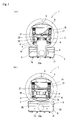
- An operating table 1 includes a patient placement table (patient placement securing means) 2, a main body 3, engaging pieces 4, 4, and so on, a drive control unit 5, and a similar member.
- the patient placement table 2 is to place and secure a patient P in a required posture.
- the main body 3 supports the patient placement table 2.
- the engaging pieces 4, 4, and so on function as coupling means that removably couple the patient placement table 2 to the main body 3.
- the drive control unit 5 controls a driving of a motor 14, which rotates the patient placement table 2, and a similar member.
- the patient placement table 2 and the main body 3 are separatable as necessary.
- the main body 3 includes a base 6, which functions as a foundation, a front side annular portion 7, a rear side annular portion 8, a lower side beam 10, an upper side beam 9, and a similar member.
- the front side annular portion 7 and the rear side annular portion 8 incorporate a rotation mechanism to rotate the patient placement table 2.
- the lower side beam 10 and the upper side beam 9 place and hold the patient placement table 2.
- the base 6 is made of a metal plate formed into a longitudinally-elongated flat rectangular parallelepiped shape whose side edge on one side is notched.
- the base 6 has casters 11, 11, and so on to move, at near four corners on the lower surface and securing means 12, 12, and so on to secure itself at a movement destination.
- the longitudinally-elongated rectangular-parallelepiped-shaped drive control unit 5 is installed on the rear surface of the base 6.
- This drive control unit 5 incorporates a controller (not illustrated) to control a rotation angle of the patient placement table 2, a controller (not illustrated) to control a height position when a pressing plate 17 is moved up and down, and a similar member.
- the base 6 internally includes the motor 14 at the approximately center of the base 6.
- the motor 14 rotates the patient placement table 2 with a head-feet direction of the patient P as a rotation axis to secure the patient placement table 2 at any given rotation angle.
- the base 6 internally includes a long shaft 25 vertically across the front-to-rear. Gears 24a and 24b are fixedly secured to respective both ends on the front and the rear of this shaft 25. A gear (not illustrated) of a main shaft of the motor 14 meshes with a gear (not illustrated) at the center of the shaft 25. A rotation force of the motor 14 is transmitted to the front and the rear gears 24a and 24b via the shaft 25.
- Both the front side annular portion 7 and the rear side annular portion 8 are formed by coating annular inner ring-shaped gears (not illustrated) and outer ring-shaped frames (not illustrated), which are relatively rotatable, with doughnut-shaped housings having hollows.
- the outer ring-shaped frame is fixedly secured to the base 6.
- the inner ring-shaped gears each mesh with the gears 24a and 24b, which are disposed at both ends of the shaft 25.
- both the upper side beam 9 and the lower side beam 10 are formed into an I shape in plan view where both right and left side portions of longitudinally-elongated rectangle are largely notched.
- Outer surfaces of parts near front and rear end edges (wide width parts) are each fixedly secured to the inner ring-shaped gear, which is rotatably incorporated into the front side annular portion 7, and to the inner ring-shaped gear, which is rotatably incorporated into the rear side annular portion 8.
- the lower surface of the upper side beam 9 is disposed parallel to the top surface of the lower side beam 10 with a predetermined distance.
- ball bearings (movement and load assistance means) 26, 26, and so on are fitted to two parallel frames (not illustrated), which are disposed along a front-rear direction.
- the ball bearings 26, 26, and so on for smoothly moving and loading the patient onto the patient placement table 2 are rotatably disposed with a part of the upper portions projecting from the surface of the lower side beam 10.
- the quadrangular prism-shaped engaging pieces 4, 4, and so on are disposed near four corners on the top surface of the lower side beam 10 so as to be slidable to the inside and the outside by an air cylinder mechanism with the longitudinal direction matched with a width direction of the patient placement table 2.
- the engaging pieces 4, 4, and so on function as the coupling means to removably couple the patient placement table 2 to the main body 3.
- Elastic members 22 and 23 are mounted at the front and the rear of the lower surface of the pressing plate 17.
- a reinforcing frame 21 is mounted to the top surface of the pressing plate 17. A part of this reinforcing frame 21 droops from the right and left of the pressing plate 17.
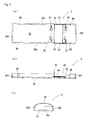
- Fig. 5 illustrates the patient placement table 2 separated from the main body 3.
- the patient placement table 2 is made of a transparent synthetic resin and has a box shape (a box shape whose top surface is open) formed by disposing side plates 32a, 32b, 32c, and 32d with predetermined width upright near the front, rear, right, and left end edges of a rectangular bottom plate 31.
- the patient placement table 2 internally lays an elastic member 20 made of polyurethane or a similar material.
- Band members 37, 37, and so on are symmetrically disposed by two at each of the front and the rear on the front side of the bottom plate 31.
- the band members 37, 37, and so on couple belts to secure (restrain) the patient at the required posture (a supine position, an abdominal position, or a similar position).
- the right and left side plates 32a and 32b have cutouts (notches) 33 with constant width at the front side parts.
- a plurality of taps 34, 34, and so on are disposed on the cutouts 33.
- arch-shaped shafts 35 and 35 can be mounted (threadably mounted) at any given front and rear positions.
- the arch-shaped shafts 35 and 35 function as mounting members to mount the securing means, which secure a chest of the patient.
- rectangular engaging holes 36 and 36 are drilled near end edges at the front and the rear of the right and left side plates 32a and 32b.
- the engaging pieces 4, 4, and so on, which are on the top surface of the lower side beam 10, are insertable into the engaging holes 36 and 36.
- the patient P is placed on the bottom plate 31 (the elastic member 20) of the patient placement table 2.
- the body of the patient P is secured at the required posture (the supine position).
- the patient placement table 2 on which the patient P is thus secured is inserted from the feet side of the patient P (or the head side of the patient P) from the front of the front side annular portion 7 to the inside so as to slide the top surface of the lower side beam 10.
- the patient placement table 2 is pushed in up to a position at which the end edge of the feet side of the patient P (or the head side of the patient P) projects to the rear of the rear side annular portion 8.
- the engaging pieces 4, 4, and so on of the lower side beam 10 are engaged with the engaging holes 36 and 36 on the patient placement table 2, thus installing the patient placement table 2 to the main body 3.
- the patient placement table 2 can be smoothly pushed.
- a power source is supplied to the ball screws 18 and 18 and the pressing plate 17 is brought down up to an appropriate position at which the patient P can be loosely pushed.
- driving the motor 14 allows the patient placement table 2 to be rotated with respect to the main body 3 with the head-feet direction of the patient P as the rotation axis. That is, driving the motor 14 transmits the rotation force by the motor 14 to the front and the rear gears 24a and 24b via the shaft 25, thus rotating the gears 24a and 24b.
- the rotation of the gears 24a and 24b also rotates the inner ring-shaped gears, which mesh with the gears 24a and 24b, inside the front side annular portion 7 and the rear side annular portion 8.
- the controller incorporated into the drive control unit 5 controls the rotation angle of the motor 14 and the rotation angle of the patient placement table 2 with respect to the main body 3 is stored as necessary.
- the patient P is secured with the securing means, which are mounted to the arch-shaped shafts 35 and 35, with the breasts of the patient P drooped.
- the patient placement table 2 is rotated again by 180 degrees or any given angle such that the lower side beam 10 is positioned on the lower side.
- the coupled state of the patient placement table 2 with the engaging pieces 4, 4, and so on is released.
- the patient placement table 2 is moved and loaded on a stretcher or a similar member for examinations required for the patient P such as MRI and CT (to identify the lesion site).
- the patient placement table 2 is moved and loaded on a bed for treatment with proton beam with the stretcher or a similar member as it is (with the posture and the breasts of the patient P secured on the patient placement table 2) for treatment with proton beam on the patient P.
- the operating table 1 includes the patient placement table (the patient placement securing means) 2, the main body 3, the engaging pieces (the coupling means) 4, 4, and so on, and the motor (the rotatable drive control means) 14.
- the patient placement table 2 is to place and secure the patient P in the required posture.
- the main body 3 supports the patient placement table 2.
- the engaging pieces 4, 4, and so on removably couple the patient placement table 2 to the main body 3.
- the motor 14 rotates the patient placement table 2 with the head-feet direction of the patient as the rotation axis to hold the patient placement table 2 at any given rotation angle. Accordingly, while the body of the patient P is secured (restrained) on the patient placement table 2 in the required posture, the patient placement table 2 can be separated from the main body 3.
- the patient placement table 2 on which the patient P whose body is secured is placed is conveyed with the stretcher or a similar member for predetermined examinations on the patient P such as MRI and CT. After that, the patient placement table 2 is moved and loaded on the bed for treatment with proton beam as it is using the stretcher or a similar member. This makes the treatment with proton beam on the patient P who keeps the identical posture possible. Accordingly, with the operating table 1, the radiation therapy with proton beam can be effectively performed.
- the patient placement table 2 includes the arch-shaped shafts 35 and 35, which are the mounting members, to mount the securing means that secure a part of the body of the secured patient.
- the predetermined examinations and the radiation therapy with proton beam can be performed with the breasts of the patient P keeping away from the chest wall and secured and held with the securing means on the patient placement table 2. Accordingly, with the operating table 1, the radiation therapy with proton beam can be more effectively performed.
- the operating table 1 includes the bearing members (the movement and load assistance means) 26, 26, and so on, which use friction reduction members, on the surface (the top surface of the lower side beam 10) of the main body 3 in contact with the patient placement table 2.
- the use of the bearing member 26, 26, and so on allows the smooth separation of the patient placement table 2 from the main body 3 without applying a massive force. This also ensures moving and loading the patient placement table 2 from the stretcher or a similar member to the main body 3.
- the patient placement table 2 includes the strip-shaped side plates 32a and 32b with wide width disposed upright near both right and left end edges of the rectangular bottom plate 31.
- the cutouts 33 are disposed at a part of the side plates 32a and 32b. This ensures disposing the mounting members, which are to mount the securing means to secure a part of the body, at positions appropriate for the patient and/or an affected part to be treated.
- the operating table 1 Even if the patient placement table 2 is rotated to be any posture, the operating table 1 holds the joined part at which the patient placement table 2 joins to the main body 3 without separation. Additionally, a deviation of the relative position between the patient placement table 2 and the main body 3 is held at required accuracy. Accordingly, the operating table 1 allows the patient P to have a sense of security. Additionally, the operating table 1 ensures the irradiation of proton beam on the lesion site at extremely good accuracy to treat the patient P with proton beam or a similar beam.
- the configuration of the operating table according to the present invention is not limited to the aspects of the above-described embodiments, and configurations such as materials, shapes, structures of the patient placement securing means, the main body, the coupling means, the rotatable drive control means, the mounting member, the securing means, the movement and load assistance means, and similar means can be changed as necessary without departing from the spirit of the disclosure.
- the operating table is not limited to one that forms the cutouts on the side plates of the patient placement table like the above-described embodiment.
- the operating table can be changed to: one that forms cutouts on the bottom plate of the patient placement table, one that forms cutouts on both the side plates and the bottom plate, and one with a similar configuration.
- the operating table is not limited to one that includes the movement and load assistance means on the surface of the patient placement table in contact with the main body like the above-described embodiment.
- the operating table can be changed to: one that includes the movement and load assistance means on the surface of the main body in contact with the patient placement table, one that includes the movement and load assistance means on both surfaces of the patient placement table, and one with a similar configuration.
- the movement and load assistance means using the friction reduction member is not limited to the bearing members like the above-described embodiment, the one that uses a wheel and one with a similar configuration may be used.
- the coupling means to couple the patient placement table to the main body is not limited to one that uses air pressure like the above-described embodiment.
- the coupling means can be changed to: one that uses a hydraulic pressure and one with a similar configuration.
- the operating table is not limited to one that couples the sites near the four corners of the patient placement securing means to the main body with the coupling means like the above-described embodiment.
- the operating table can be changed to: one that couples the entire right and left side edges of the patient placement securing means to the main body, one that couples the entire outer peripheral edge of the patient placement securing means to the main body, and one with a similar configuration.
- the operating table is applicable to examinations and treatments for various diseases.
- the operating table is preferably applicable as a device used for treatment with proton beam, treatment with heavy particle beam, and examinations for breast cancer.
Landscapes
- Health & Medical Sciences (AREA)
- Engineering & Computer Science (AREA)
- Biomedical Technology (AREA)
- Life Sciences & Earth Sciences (AREA)
- Animal Behavior & Ethology (AREA)
- General Health & Medical Sciences (AREA)
- Public Health (AREA)
- Veterinary Medicine (AREA)
- Radiology & Medical Imaging (AREA)
- Nuclear Medicine, Radiotherapy & Molecular Imaging (AREA)
- Pathology (AREA)
- Medical Informatics (AREA)
- Physics & Mathematics (AREA)
- Biophysics (AREA)
- High Energy & Nuclear Physics (AREA)
- Optics & Photonics (AREA)
- Heart & Thoracic Surgery (AREA)
- Molecular Biology (AREA)
- Surgery (AREA)
- Accommodation For Nursing Or Treatment Tables (AREA)
- Radiation-Therapy Devices (AREA)
Applications Claiming Priority (2)
| Application Number | Priority Date | Filing Date | Title |
|---|---|---|---|
| JP2014046982 | 2014-03-10 | ||
| PCT/JP2015/056891 WO2015137290A1 (fr) | 2014-03-10 | 2015-03-10 | Table d'opération |
Publications (3)
| Publication Number | Publication Date |
|---|---|
| EP3095427A1 true EP3095427A1 (fr) | 2016-11-23 |
| EP3095427A4 EP3095427A4 (fr) | 2017-09-27 |
| EP3095427B1 EP3095427B1 (fr) | 2019-09-18 |
Family
ID=54071734
Family Applications (1)
| Application Number | Title | Priority Date | Filing Date |
|---|---|---|---|
| EP15761445.4A Active EP3095427B1 (fr) | 2014-03-10 | 2015-03-10 | Table d'opération |
Country Status (9)
| Country | Link |
|---|---|
| US (1) | US10322051B2 (fr) |
| EP (1) | EP3095427B1 (fr) |
| JP (1) | JP6244011B2 (fr) |
| KR (1) | KR20170008203A (fr) |
| CN (1) | CN106456430B (fr) |
| BR (1) | BR112016020790A2 (fr) |
| CA (1) | CA2942252A1 (fr) |
| RU (1) | RU2694910C2 (fr) |
| WO (1) | WO2015137290A1 (fr) |
Families Citing this family (5)
| Publication number | Priority date | Publication date | Assignee | Title |
|---|---|---|---|---|
| CN109952041A (zh) * | 2016-10-20 | 2019-06-28 | 株式会社新日本科学 | 文胸的制造方法 |
| US11020304B2 (en) * | 2017-08-08 | 2021-06-01 | Warsaw Orthopedic, Inc. | Surgical frame including main beam for facilitating patient access |
| EP3639893B1 (fr) * | 2018-10-17 | 2024-12-04 | Ion Beam Applications | Système de thérapie par particules avec distribution de faisceau rotatif |
| US20230285796A1 (en) * | 2020-08-03 | 2023-09-14 | Rudy Alexander Riveron | Tissue configuration platform |
| JP2024511277A (ja) | 2021-02-19 | 2024-03-13 | メビオン・メディカル・システムズ・インコーポレーテッド | 粒子線治療システムのためのガントリー |
Family Cites Families (14)
| Publication number | Priority date | Publication date | Assignee | Title |
|---|---|---|---|---|
| RU2039546C1 (ru) * | 1992-12-29 | 1995-07-20 | Малое государственное предприятие "Энергетик" | Офтальмологический операционный стол |
| US5590429A (en) | 1995-09-13 | 1997-01-07 | General Electric Company | Electrophysiology table |
| US6260220B1 (en) * | 1997-02-13 | 2001-07-17 | Orthopedic Systems, Inc. | Surgical table for lateral procedures |
| JP2001513365A (ja) | 1997-08-08 | 2001-09-04 | ヒル−ロム,インコーポレイティド | うつ伏せベッド |
| EP1083857B1 (fr) * | 1998-06-03 | 2004-03-03 | Alliance Investments Ltd | Lit therapeutique |
| AU4368100A (en) * | 1999-04-21 | 2000-11-02 | Vincent L. Babson | Proning bed |
| FR2818116B1 (fr) * | 2000-12-19 | 2004-08-27 | Ge Med Sys Global Tech Co Llc | Appareil de mammographie |
| US6671905B2 (en) * | 2001-03-29 | 2004-01-06 | Kci Licensing, Inc. | Prone positioning therapeutic bed |
| CN100542511C (zh) * | 2004-10-31 | 2009-09-23 | 文宜平 | 轻便通用翻身病床 |
| US9186291B2 (en) * | 2005-02-22 | 2015-11-17 | Roger P. Jackson | Patient positioning support structure with trunk translator |
| JP2011220771A (ja) * | 2010-04-07 | 2011-11-04 | Shimadzu Corp | 乳房検診用放射線断層撮影装置 |
| US8584281B2 (en) * | 2011-04-07 | 2013-11-19 | Mizuho Orthopedic Systems, Inc | Surgery table having coordinated motion |
| US20130019876A1 (en) * | 2011-07-21 | 2013-01-24 | Nicholas Zacharopoulos | Breast Treatment Device |
| US9498397B2 (en) * | 2012-04-16 | 2016-11-22 | Allen Medical Systems, Inc. | Dual column surgical support system |
-
2015
- 2015-03-10 WO PCT/JP2015/056891 patent/WO2015137290A1/fr not_active Ceased
- 2015-03-10 JP JP2016507740A patent/JP6244011B2/ja active Active
- 2015-03-10 CN CN201580012813.5A patent/CN106456430B/zh active Active
- 2015-03-10 BR BR112016020790-4A patent/BR112016020790A2/pt not_active Application Discontinuation
- 2015-03-10 US US15/124,371 patent/US10322051B2/en active Active
- 2015-03-10 CA CA2942252A patent/CA2942252A1/fr not_active Abandoned
- 2015-03-10 KR KR1020167028043A patent/KR20170008203A/ko not_active Withdrawn
- 2015-03-10 EP EP15761445.4A patent/EP3095427B1/fr active Active
- 2015-03-10 RU RU2016139362A patent/RU2694910C2/ru not_active IP Right Cessation
Also Published As
| Publication number | Publication date |
|---|---|
| RU2016139362A3 (fr) | 2018-09-11 |
| BR112016020790A2 (pt) | 2018-01-23 |
| US20170020761A1 (en) | 2017-01-26 |
| KR20170008203A (ko) | 2017-01-23 |
| WO2015137290A1 (fr) | 2015-09-17 |
| EP3095427B1 (fr) | 2019-09-18 |
| CA2942252A1 (fr) | 2015-09-17 |
| RU2016139362A (ru) | 2018-04-10 |
| JP6244011B2 (ja) | 2017-12-06 |
| US10322051B2 (en) | 2019-06-18 |
| RU2694910C2 (ru) | 2019-07-18 |
| EP3095427A4 (fr) | 2017-09-27 |
| CN106456430A (zh) | 2017-02-22 |
| JPWO2015137290A1 (ja) | 2017-06-15 |
| CN106456430B (zh) | 2019-11-12 |
Similar Documents
| Publication | Publication Date | Title |
|---|---|---|
| US10322051B2 (en) | Operating table | |
| US6152599A (en) | Tomotherapy treatment table positioning device | |
| JP3577221B2 (ja) | 放射線治療用ベッドシステム | |
| JP6538631B2 (ja) | 粒子線医療装置およびその運転方法 | |
| WO2016044966A1 (fr) | Lit de traitement à mouvement angulaire multiple | |
| US20130276232A1 (en) | Iso-roll table | |
| CN108433741A (zh) | 回转装置和包括该回转装置的医疗设备 | |
| CN108348209A (zh) | 放射线照射装置 | |
| WO2017032345A1 (fr) | Dispositif de radiothérapie à modulation d'intensité conforme | |
| TW201902530A (zh) | 粒子束醫療裝置 | |
| CN111714148B (zh) | 患者支承装置和医学成像装置 | |
| KR101796512B1 (ko) | 유지 보수가 편리한 듀얼 헤드 타입의 방사선 치료장치 | |
| CN105101876A (zh) | X射线装置 | |
| US10143860B2 (en) | Radiation therapy apparatus | |
| CN106693213B (zh) | 加速器治疗装置用底座及加速器治疗装置 | |
| JP2004255160A (ja) | 放射線治療用複合装置 | |
| CN111249628A (zh) | 治疗床及放疗设备 | |
| US10813602B2 (en) | Patient support apparatus with six degrees of freedom | |
| US20150374567A1 (en) | Patient transportation system | |
| CN107854780A (zh) | 载人旋转舱装置 | |
| EP4732895A1 (fr) | Dispositif de réglage pour radiothérapie, procédé de réglage et système de transport | |
| Sommer | Industrial robots for patient support | |
| Zhang et al. | Recent Patents on Radiotherapy Bed | |
| CN119185801A (zh) | 用于放射治疗的调节装置、调节方法及载置系统 | |
| JP2012061039A (ja) | 放射線治療寝台用天板及び放射線治療寝台 |
Legal Events
| Date | Code | Title | Description |
|---|---|---|---|
| PUAI | Public reference made under article 153(3) epc to a published international application that has entered the european phase |
Free format text: ORIGINAL CODE: 0009012 |
|
| 17P | Request for examination filed |
Effective date: 20160819 |
|
| AK | Designated contracting states |
Kind code of ref document: A1 Designated state(s): AL AT BE BG CH CY CZ DE DK EE ES FI FR GB GR HR HU IE IS IT LI LT LU LV MC MK MT NL NO PL PT RO RS SE SI SK SM TR |
|
| AX | Request for extension of the european patent |
Extension state: BA ME |
|
| DAV | Request for validation of the european patent (deleted) | ||
| DAX | Request for extension of the european patent (deleted) | ||
| A4 | Supplementary search report drawn up and despatched |
Effective date: 20170830 |
|
| RIC1 | Information provided on ipc code assigned before grant |
Ipc: A61G 13/00 20060101AFI20170824BHEP Ipc: A61G 7/00 20060101ALI20170824BHEP Ipc: A61G 13/12 20060101ALI20170824BHEP Ipc: A61B 6/04 20060101ALI20170824BHEP Ipc: A61N 5/10 20060101ALI20170824BHEP Ipc: A61G 13/02 20060101ALI20170824BHEP |
|
| STAA | Information on the status of an ep patent application or granted ep patent |
Free format text: STATUS: EXAMINATION IS IN PROGRESS |
|
| 17Q | First examination report despatched |
Effective date: 20180613 |
|
| GRAP | Despatch of communication of intention to grant a patent |
Free format text: ORIGINAL CODE: EPIDOSNIGR1 |
|
| STAA | Information on the status of an ep patent application or granted ep patent |
Free format text: STATUS: GRANT OF PATENT IS INTENDED |
|
| INTG | Intention to grant announced |
Effective date: 20190404 |
|
| GRAS | Grant fee paid |
Free format text: ORIGINAL CODE: EPIDOSNIGR3 |
|
| GRAA | (expected) grant |
Free format text: ORIGINAL CODE: 0009210 |
|
| STAA | Information on the status of an ep patent application or granted ep patent |
Free format text: STATUS: THE PATENT HAS BEEN GRANTED |
|
| AK | Designated contracting states |
Kind code of ref document: B1 Designated state(s): AL AT BE BG CH CY CZ DE DK EE ES FI FR GB GR HR HU IE IS IT LI LT LU LV MC MK MT NL NO PL PT RO RS SE SI SK SM TR |
|
| REG | Reference to a national code |
Ref country code: GB Ref legal event code: FG4D |
|
| REG | Reference to a national code |
Ref country code: CH Ref legal event code: EP |
|
| REG | Reference to a national code |
Ref country code: DE Ref legal event code: R096 Ref document number: 602015038276 Country of ref document: DE |
|
| REG | Reference to a national code |
Ref country code: AT Ref legal event code: REF Ref document number: 1180443 Country of ref document: AT Kind code of ref document: T Effective date: 20191015 |
|
| REG | Reference to a national code |
Ref country code: IE Ref legal event code: FG4D |
|
| REG | Reference to a national code |
Ref country code: NL Ref legal event code: MP Effective date: 20190918 |
|
| PG25 | Lapsed in a contracting state [announced via postgrant information from national office to epo] |
Ref country code: LT Free format text: LAPSE BECAUSE OF FAILURE TO SUBMIT A TRANSLATION OF THE DESCRIPTION OR TO PAY THE FEE WITHIN THE PRESCRIBED TIME-LIMIT Effective date: 20190918 Ref country code: FI Free format text: LAPSE BECAUSE OF FAILURE TO SUBMIT A TRANSLATION OF THE DESCRIPTION OR TO PAY THE FEE WITHIN THE PRESCRIBED TIME-LIMIT Effective date: 20190918 Ref country code: BG Free format text: LAPSE BECAUSE OF FAILURE TO SUBMIT A TRANSLATION OF THE DESCRIPTION OR TO PAY THE FEE WITHIN THE PRESCRIBED TIME-LIMIT Effective date: 20191218 Ref country code: NO Free format text: LAPSE BECAUSE OF FAILURE TO SUBMIT A TRANSLATION OF THE DESCRIPTION OR TO PAY THE FEE WITHIN THE PRESCRIBED TIME-LIMIT Effective date: 20191218 Ref country code: SE Free format text: LAPSE BECAUSE OF FAILURE TO SUBMIT A TRANSLATION OF THE DESCRIPTION OR TO PAY THE FEE WITHIN THE PRESCRIBED TIME-LIMIT Effective date: 20190918 Ref country code: HR Free format text: LAPSE BECAUSE OF FAILURE TO SUBMIT A TRANSLATION OF THE DESCRIPTION OR TO PAY THE FEE WITHIN THE PRESCRIBED TIME-LIMIT Effective date: 20190918 |
|
| REG | Reference to a national code |
Ref country code: LT Ref legal event code: MG4D |
|
| PG25 | Lapsed in a contracting state [announced via postgrant information from national office to epo] |
Ref country code: RS Free format text: LAPSE BECAUSE OF FAILURE TO SUBMIT A TRANSLATION OF THE DESCRIPTION OR TO PAY THE FEE WITHIN THE PRESCRIBED TIME-LIMIT Effective date: 20190918 Ref country code: GR Free format text: LAPSE BECAUSE OF FAILURE TO SUBMIT A TRANSLATION OF THE DESCRIPTION OR TO PAY THE FEE WITHIN THE PRESCRIBED TIME-LIMIT Effective date: 20191219 Ref country code: AL Free format text: LAPSE BECAUSE OF FAILURE TO SUBMIT A TRANSLATION OF THE DESCRIPTION OR TO PAY THE FEE WITHIN THE PRESCRIBED TIME-LIMIT Effective date: 20190918 Ref country code: LV Free format text: LAPSE BECAUSE OF FAILURE TO SUBMIT A TRANSLATION OF THE DESCRIPTION OR TO PAY THE FEE WITHIN THE PRESCRIBED TIME-LIMIT Effective date: 20190918 |
|
| REG | Reference to a national code |
Ref country code: AT Ref legal event code: MK05 Ref document number: 1180443 Country of ref document: AT Kind code of ref document: T Effective date: 20190918 |
|
| PG25 | Lapsed in a contracting state [announced via postgrant information from national office to epo] |
Ref country code: PT Free format text: LAPSE BECAUSE OF FAILURE TO SUBMIT A TRANSLATION OF THE DESCRIPTION OR TO PAY THE FEE WITHIN THE PRESCRIBED TIME-LIMIT Effective date: 20200120 Ref country code: PL Free format text: LAPSE BECAUSE OF FAILURE TO SUBMIT A TRANSLATION OF THE DESCRIPTION OR TO PAY THE FEE WITHIN THE PRESCRIBED TIME-LIMIT Effective date: 20190918 Ref country code: AT Free format text: LAPSE BECAUSE OF FAILURE TO SUBMIT A TRANSLATION OF THE DESCRIPTION OR TO PAY THE FEE WITHIN THE PRESCRIBED TIME-LIMIT Effective date: 20190918 Ref country code: EE Free format text: LAPSE BECAUSE OF FAILURE TO SUBMIT A TRANSLATION OF THE DESCRIPTION OR TO PAY THE FEE WITHIN THE PRESCRIBED TIME-LIMIT Effective date: 20190918 Ref country code: IT Free format text: LAPSE BECAUSE OF FAILURE TO SUBMIT A TRANSLATION OF THE DESCRIPTION OR TO PAY THE FEE WITHIN THE PRESCRIBED TIME-LIMIT Effective date: 20190918 Ref country code: ES Free format text: LAPSE BECAUSE OF FAILURE TO SUBMIT A TRANSLATION OF THE DESCRIPTION OR TO PAY THE FEE WITHIN THE PRESCRIBED TIME-LIMIT Effective date: 20190918 Ref country code: RO Free format text: LAPSE BECAUSE OF FAILURE TO SUBMIT A TRANSLATION OF THE DESCRIPTION OR TO PAY THE FEE WITHIN THE PRESCRIBED TIME-LIMIT Effective date: 20190918 Ref country code: NL Free format text: LAPSE BECAUSE OF FAILURE TO SUBMIT A TRANSLATION OF THE DESCRIPTION OR TO PAY THE FEE WITHIN THE PRESCRIBED TIME-LIMIT Effective date: 20190918 |
|
| PG25 | Lapsed in a contracting state [announced via postgrant information from national office to epo] |
Ref country code: SM Free format text: LAPSE BECAUSE OF FAILURE TO SUBMIT A TRANSLATION OF THE DESCRIPTION OR TO PAY THE FEE WITHIN THE PRESCRIBED TIME-LIMIT Effective date: 20190918 Ref country code: SK Free format text: LAPSE BECAUSE OF FAILURE TO SUBMIT A TRANSLATION OF THE DESCRIPTION OR TO PAY THE FEE WITHIN THE PRESCRIBED TIME-LIMIT Effective date: 20190918 Ref country code: CZ Free format text: LAPSE BECAUSE OF FAILURE TO SUBMIT A TRANSLATION OF THE DESCRIPTION OR TO PAY THE FEE WITHIN THE PRESCRIBED TIME-LIMIT Effective date: 20190918 Ref country code: IS Free format text: LAPSE BECAUSE OF FAILURE TO SUBMIT A TRANSLATION OF THE DESCRIPTION OR TO PAY THE FEE WITHIN THE PRESCRIBED TIME-LIMIT Effective date: 20200224 |
|
| REG | Reference to a national code |
Ref country code: DE Ref legal event code: R097 Ref document number: 602015038276 Country of ref document: DE |
|
| PLBE | No opposition filed within time limit |
Free format text: ORIGINAL CODE: 0009261 |
|
| STAA | Information on the status of an ep patent application or granted ep patent |
Free format text: STATUS: NO OPPOSITION FILED WITHIN TIME LIMIT |
|
| PG2D | Information on lapse in contracting state deleted |
Ref country code: IS |
|
| PG25 | Lapsed in a contracting state [announced via postgrant information from national office to epo] |
Ref country code: DK Free format text: LAPSE BECAUSE OF FAILURE TO SUBMIT A TRANSLATION OF THE DESCRIPTION OR TO PAY THE FEE WITHIN THE PRESCRIBED TIME-LIMIT Effective date: 20190918 Ref country code: IS Free format text: LAPSE BECAUSE OF FAILURE TO SUBMIT A TRANSLATION OF THE DESCRIPTION OR TO PAY THE FEE WITHIN THE PRESCRIBED TIME-LIMIT Effective date: 20200119 |
|
| 26N | No opposition filed |
Effective date: 20200619 |
|
| PG25 | Lapsed in a contracting state [announced via postgrant information from national office to epo] |
Ref country code: SI Free format text: LAPSE BECAUSE OF FAILURE TO SUBMIT A TRANSLATION OF THE DESCRIPTION OR TO PAY THE FEE WITHIN THE PRESCRIBED TIME-LIMIT Effective date: 20190918 |
|
| PG25 | Lapsed in a contracting state [announced via postgrant information from national office to epo] |
Ref country code: MC Free format text: LAPSE BECAUSE OF FAILURE TO SUBMIT A TRANSLATION OF THE DESCRIPTION OR TO PAY THE FEE WITHIN THE PRESCRIBED TIME-LIMIT Effective date: 20190918 |
|
| REG | Reference to a national code |
Ref country code: CH Ref legal event code: PL |
|
| REG | Reference to a national code |
Ref country code: BE Ref legal event code: MM Effective date: 20200331 |
|
| PG25 | Lapsed in a contracting state [announced via postgrant information from national office to epo] |
Ref country code: LU Free format text: LAPSE BECAUSE OF NON-PAYMENT OF DUE FEES Effective date: 20200310 |
|
| PG25 | Lapsed in a contracting state [announced via postgrant information from national office to epo] |
Ref country code: CH Free format text: LAPSE BECAUSE OF NON-PAYMENT OF DUE FEES Effective date: 20200331 Ref country code: IE Free format text: LAPSE BECAUSE OF NON-PAYMENT OF DUE FEES Effective date: 20200310 Ref country code: LI Free format text: LAPSE BECAUSE OF NON-PAYMENT OF DUE FEES Effective date: 20200331 |
|
| PG25 | Lapsed in a contracting state [announced via postgrant information from national office to epo] |
Ref country code: BE Free format text: LAPSE BECAUSE OF NON-PAYMENT OF DUE FEES Effective date: 20200331 |
|
| PG25 | Lapsed in a contracting state [announced via postgrant information from national office to epo] |
Ref country code: TR Free format text: LAPSE BECAUSE OF FAILURE TO SUBMIT A TRANSLATION OF THE DESCRIPTION OR TO PAY THE FEE WITHIN THE PRESCRIBED TIME-LIMIT Effective date: 20190918 Ref country code: MT Free format text: LAPSE BECAUSE OF FAILURE TO SUBMIT A TRANSLATION OF THE DESCRIPTION OR TO PAY THE FEE WITHIN THE PRESCRIBED TIME-LIMIT Effective date: 20190918 Ref country code: CY Free format text: LAPSE BECAUSE OF FAILURE TO SUBMIT A TRANSLATION OF THE DESCRIPTION OR TO PAY THE FEE WITHIN THE PRESCRIBED TIME-LIMIT Effective date: 20190918 |
|
| PG25 | Lapsed in a contracting state [announced via postgrant information from national office to epo] |
Ref country code: MK Free format text: LAPSE BECAUSE OF FAILURE TO SUBMIT A TRANSLATION OF THE DESCRIPTION OR TO PAY THE FEE WITHIN THE PRESCRIBED TIME-LIMIT Effective date: 20190918 |
|
| PGFP | Annual fee paid to national office [announced via postgrant information from national office to epo] |
Ref country code: GB Payment date: 20260202 Year of fee payment: 12 |
|
| PGFP | Annual fee paid to national office [announced via postgrant information from national office to epo] |
Ref country code: DE Payment date: 20260128 Year of fee payment: 12 |
|
| PGFP | Annual fee paid to national office [announced via postgrant information from national office to epo] |
Ref country code: FR Payment date: 20260209 Year of fee payment: 12 |