EP3095473A1 - Systèmes et procédés permettant de distribuer un fluide dans le cadre du traitement de plaies par un pansement - Google Patents
Systèmes et procédés permettant de distribuer un fluide dans le cadre du traitement de plaies par un pansement Download PDFInfo
- Publication number
- EP3095473A1 EP3095473A1 EP16177808.9A EP16177808A EP3095473A1 EP 3095473 A1 EP3095473 A1 EP 3095473A1 EP 16177808 A EP16177808 A EP 16177808A EP 3095473 A1 EP3095473 A1 EP 3095473A1
- Authority
- EP
- European Patent Office
- Prior art keywords
- fluid
- negative pressure
- wound dressing
- dressing
- wound
- Prior art date
- Legal status (The legal status is an assumption and is not a legal conclusion. Google has not performed a legal analysis and makes no representation as to the accuracy of the status listed.)
- Granted
Links
Images


Classifications
-
- A—HUMAN NECESSITIES
- A61—MEDICAL OR VETERINARY SCIENCE; HYGIENE
- A61M—DEVICES FOR INTRODUCING MEDIA INTO, OR ONTO, THE BODY; DEVICES FOR TRANSDUCING BODY MEDIA OR FOR TAKING MEDIA FROM THE BODY; DEVICES FOR PRODUCING OR ENDING SLEEP OR STUPOR
- A61M3/00—Medical syringes, e.g. enemata; Irrigators
- A61M3/02—Enemata; Irrigators
- A61M3/0204—Physical characteristics of the irrigation fluid, e.g. conductivity or turbidity
- A61M3/0208—Physical characteristics of the irrigation fluid, e.g. conductivity or turbidity before use
-
- A—HUMAN NECESSITIES
- A61—MEDICAL OR VETERINARY SCIENCE; HYGIENE
- A61M—DEVICES FOR INTRODUCING MEDIA INTO, OR ONTO, THE BODY; DEVICES FOR TRANSDUCING BODY MEDIA OR FOR TAKING MEDIA FROM THE BODY; DEVICES FOR PRODUCING OR ENDING SLEEP OR STUPOR
- A61M1/00—Suction or pumping devices for medical purposes; Devices for carrying-off, for treatment of, or for carrying-over, body-liquids; Drainage systems
- A61M1/71—Suction drainage systems
- A61M1/74—Suction control
-
- A—HUMAN NECESSITIES
- A61—MEDICAL OR VETERINARY SCIENCE; HYGIENE
- A61M—DEVICES FOR INTRODUCING MEDIA INTO, OR ONTO, THE BODY; DEVICES FOR TRANSDUCING BODY MEDIA OR FOR TAKING MEDIA FROM THE BODY; DEVICES FOR PRODUCING OR ENDING SLEEP OR STUPOR
- A61M1/00—Suction or pumping devices for medical purposes; Devices for carrying-off, for treatment of, or for carrying-over, body-liquids; Drainage systems
- A61M1/84—Drainage tubes; Aspiration tips
- A61M1/85—Drainage tubes; Aspiration tips with gas or fluid supply means, e.g. for supplying rinsing fluids or anticoagulants
-
- A—HUMAN NECESSITIES
- A61—MEDICAL OR VETERINARY SCIENCE; HYGIENE
- A61M—DEVICES FOR INTRODUCING MEDIA INTO, OR ONTO, THE BODY; DEVICES FOR TRANSDUCING BODY MEDIA OR FOR TAKING MEDIA FROM THE BODY; DEVICES FOR PRODUCING OR ENDING SLEEP OR STUPOR
- A61M1/00—Suction or pumping devices for medical purposes; Devices for carrying-off, for treatment of, or for carrying-over, body-liquids; Drainage systems
- A61M1/90—Negative pressure wound therapy devices, i.e. devices for applying suction to a wound to promote healing, e.g. including a vacuum dressing
- A61M1/92—Negative pressure wound therapy devices, i.e. devices for applying suction to a wound to promote healing, e.g. including a vacuum dressing with liquid supply means
-
- A—HUMAN NECESSITIES
- A61—MEDICAL OR VETERINARY SCIENCE; HYGIENE
- A61M—DEVICES FOR INTRODUCING MEDIA INTO, OR ONTO, THE BODY; DEVICES FOR TRANSDUCING BODY MEDIA OR FOR TAKING MEDIA FROM THE BODY; DEVICES FOR PRODUCING OR ENDING SLEEP OR STUPOR
- A61M3/00—Medical syringes, e.g. enemata; Irrigators
- A61M3/02—Enemata; Irrigators
- A61M3/0204—Physical characteristics of the irrigation fluid, e.g. conductivity or turbidity
- A61M3/0216—Pressure
-
- A—HUMAN NECESSITIES
- A61—MEDICAL OR VETERINARY SCIENCE; HYGIENE
- A61M—DEVICES FOR INTRODUCING MEDIA INTO, OR ONTO, THE BODY; DEVICES FOR TRANSDUCING BODY MEDIA OR FOR TAKING MEDIA FROM THE BODY; DEVICES FOR PRODUCING OR ENDING SLEEP OR STUPOR
- A61M3/00—Medical syringes, e.g. enemata; Irrigators
- A61M3/02—Enemata; Irrigators
- A61M3/0204—Physical characteristics of the irrigation fluid, e.g. conductivity or turbidity
- A61M3/022—Volume; Flow rate
-
- A—HUMAN NECESSITIES
- A61—MEDICAL OR VETERINARY SCIENCE; HYGIENE
- A61M—DEVICES FOR INTRODUCING MEDIA INTO, OR ONTO, THE BODY; DEVICES FOR TRANSDUCING BODY MEDIA OR FOR TAKING MEDIA FROM THE BODY; DEVICES FOR PRODUCING OR ENDING SLEEP OR STUPOR
- A61M2205/00—General characteristics of the apparatus
- A61M2205/15—Detection of leaks
-
- A—HUMAN NECESSITIES
- A61—MEDICAL OR VETERINARY SCIENCE; HYGIENE
- A61M—DEVICES FOR INTRODUCING MEDIA INTO, OR ONTO, THE BODY; DEVICES FOR TRANSDUCING BODY MEDIA OR FOR TAKING MEDIA FROM THE BODY; DEVICES FOR PRODUCING OR ENDING SLEEP OR STUPOR
- A61M2205/00—General characteristics of the apparatus
- A61M2205/33—Controlling, regulating or measuring
- A61M2205/3331—Pressure; Flow
- A61M2205/3334—Measuring or controlling the flow rate
-
- A—HUMAN NECESSITIES
- A61—MEDICAL OR VETERINARY SCIENCE; HYGIENE
- A61M—DEVICES FOR INTRODUCING MEDIA INTO, OR ONTO, THE BODY; DEVICES FOR TRANSDUCING BODY MEDIA OR FOR TAKING MEDIA FROM THE BODY; DEVICES FOR PRODUCING OR ENDING SLEEP OR STUPOR
- A61M2205/00—General characteristics of the apparatus
- A61M2205/33—Controlling, regulating or measuring
- A61M2205/3331—Pressure; Flow
- A61M2205/3344—Measuring or controlling pressure at the body treatment site
Definitions
- the subject matter of this specification relates generally to healing of wounds and wound-treatment therapies. More particularly, but not by way of limitation, the subject matter relates to systems and methods for improving fluid-instillation and negative pressure wound therapy (NPWT) apparatuses and methods.
- NGWT negative pressure wound therapy
- reduced pressure is applied to tissue through a porous pad or other manifold device.
- the porous pad contains cells or pores that are capable of distributing reduced pressure to the tissue and channeling fluids that are drawn from the tissue.
- the porous pad may be incorporated into a dressing having other components that facilitate treatment.
- Typical instillation therapy instills fluid into a wound under a low positive pressure. For maximum therapeutic effect, the instilled fluid should reach all exposed tissue surfaces.
- the practice of fully filling a wound with instillation fluid, combined with the application of porous wound fillers and negative pressure to help distribute fluid, are techniques used to try and achieve good instillation therapy. Such techniques include numerous disadvantages, including difficulty in delivering the desired volume of fluid without overfilling the system and causing leakage.
- Certain embodiments comprise a system configured for delivering fluid to a negative pressure wound therapy dressing, wherein the system comprises a biasing mechanism configured to compress a fluid reservoir.
- the system comprises a housing configured to receive a fluid reservoir.
- the biasing mechanism is configured to secure a fluid reservoir within the housing.
- the biasing mechanism is configured as a spring.
- the spring is a constant-force spring.
- the positive pressure exerted on the fluid in the reservoir is greater than or equal to approximately 75 mm Hg.
- the fluid reservoir is a polyethylene bag.
- a control circuit configured to control a flow of fluid from the fluid reservoir.
- the control circuit is coupled to a flow sensor configured to detect the flow rate of fluid from the fluid reservoir and to provide a fluid flow rate signal to the control circuit.
- the control circuit is coupled to a flow controller.
- the flow controller may be adapted to be positioned in fluid communication between the fluid reservoir and the wound therapy dressing.
- the flow controller is configured as a control valve.
- Certain embodiments also comprise a conduit in fluid communication with a wound dressing.
- Particular embodiments also comprise a negative pressure source in fluid communication with the wound dressing.
- the biasing mechanism is disposed within a receptacle configured to extend from a housing.
- Certain embodiments also include a method of delivering a fluid to a wound dressing.
- the method comprises exerting a force from a biasing mechanism on a fluid reservoir and compressing the fluid reservoir, wherein a fluid is directed from the fluid reservoir to the wound dressing via a conduit.
- Specific embodiments further comprise controlling a flow of fluid from the fluid reservoir via a flow controller.
- the flow controller is controlled by a control circuit.
- the biasing mechanism is a spring.
- Particular embodiments also comprise securing the fluid reservoir within a housing via the biasing mechanism. Exerting the force from the biasing mechanism may create a positive pressure on the fluid in the reservoir that is, for example, greater than or equal to approximately 75 mm Hg.
- Certain embodiments also comprise providing a negative pressure to the wound dressing.
- Particular embodiments also include a method of providing instillation fluid and negative pressure to a wound dressing.
- the method comprises: applying negative pressure to the wound dressing while inhibiting instillation fluid flow to the wound dressing; ceasing to apply negative pressure to the wound dressing and measuring a volumetric leak rate from the wound dressing; enabling instillation fluid flow to the wound dressing; measuring the flow rate of the instillation fluid and the pressure at the wound dressing; verifying wound dressing pressure is approximately atmospheric pressure; ceasing the flow of instillation fluid to the wound dressing; allowing the instillation fluid to remain in the wound dressing; and removing the instillation fluid from the wound dressing.
- enabling instillation fluid flow to the wound dressing comprises creating a pressure in a fluid reservoir by exerting a force from a biasing mechanism.
- the biasing mechanism is a spring.
- Specific embodiments also include a system for treating a wound with a wound dressing.
- the system comprises: a housing with a receptacle configured to receive a fluid reservoir; a biasing mechanism disposed within the receptacle for compressing the fluid reservoir; a negative pressure source disposed within the housing; and a conduit for fluidly connecting the reservoir, the negative pressure source, and the wound dressing.
- the biasing mechanism is a spring.
- the negative pressure source comprises a vacuum pump and a negative pressure controller.
- the vacuum pump and the negative pressure controller may be adapted to be controlled by a control circuit according to a negative pressure input signal received from the wound therapy dressing.
- the receptacle is slideably received within the housing and configured to extend from the housing.
- Certain embodiments also comprise a flow sensor and a flow controller coupled to the conduit. The flow sensor and the flow controller may be adapted to be positioned in fluid communication between the fluid reservoir and the wound therapy dressing.
- a system adapted to deliver fluid to a wound therapy dressing including a negative pressure source, a housing, a biasing mechanism, and a control circuit.
- the negative pressure source is adapted to be in fluid communication with the wound therapy dressing to provide negative pressure to the wound therapy dressing.
- the housing is adapted to receive a fluid reservoir, the fluid reservoir adapted to be in fluid communication with the wound therapy dressing to provide fluid from the fluid reservoir to the wound therapy dressing.
- the biasing mechanism is adapted to secure the fluid reservoir in the housing and to exert a positive pressure on the fluid in the fluid reservoir.
- the control circuit is adapted to control the negative pressure in the wound therapy dressing.
- a system adapted to deliver fluid to a wound therapy dressing including a negative pressure source, a housing, a flow sensor, a flow controller, and a control circuit.
- the negative pressure source is adapted to be in fluid communication with the wound therapy dressing to provide negative pressure to the wound therapy dressing.
- the housing is adapted to receive a fluid reservoir, the fluid reservoir adapted to be in fluid communication with the wound therapy dressing to provide fluid from the fluid reservoir to the wound therapy dressing.
- the flow sensor is adapted to be positioned in fluid communication between the fluid reservoir and the wound therapy dressing and to detect a flow rate of the fluid from the fluid reservoir to the wound therapy dressing.
- the flow controller is adapted to be positioned in fluid communication between the fluid reservoir and the wound therapy dressing and to control a flow of the fluid from the fluid reservoir to the wound therapy dressing.
- the control circuit is adapted to control the negative pressure source. Additionally, the control circuit is adapted to receive a fluid flow rate signal from the flow sensor that corresponds to the flow rate of the fluid from the fluid reservoir and a negative pressure signal that corresponds to the negative pressure in the wound therapy dressing.
- a method of providing instillation fluid and negative pressure to a wound dressing including: applying negative pressure to the wound dressing; ceasing to apply negative pressure to the wound dressing when the negative pressure in the wound dressing reaches a target negative pressure; measuring a volumetric leak rate of the negative pressure from the wound dressing; enabling instillation fluid flow to the wound dressing after the wound dressing reaches the target negative pressure, wherein the instillation fluid flow to the wound dressing is substantially inhibited prior to the negative pressure in the wound dressing reaching the target negative pressure and the volumetric leak rate being measured; measuring a flow rate of the instillation fluid to the wound dressing; monitoring the negative pressure in the wound dressing as the instillation fluid flows into the wound dressing; ceasing the instillation fluid flow to the wound dressing when the negative pressure in the wound dressing is approximately atmospheric pressure; allowing the instillation fluid to remain in the wound dressing for a predetermined time period; and removing the instillation fluid from the wound dressing after the predetermined time period.
- a method of providing instillation fluid and negative pressure to a wound dressing including applying negative pressure to the wound dressing until the negative pressure in the wound dressing reaches a target negative pressure; determining a required volumetric flow rate of the negative pressure to the wound dressing to maintain the negative pressure in the wound dressing substantially at the target negative pressure, the required volumetric flow rate of the negative pressure substantially corresponding to a volumetric leak rate of the negative pressure from the wound dressing; enabling instillation fluid flow to the wound dressing after the wound dressing reaches the target negative pressure; monitoring the negative pressure in the wound dressing as the instillation fluid flows into the wound dressing; applying negative pressure to the wound dressing while the instillation fluid flows into the wound dressing, wherein a flow rate of the negative pressure applied while the instillation fluid flows substantially corresponds to the volumetric leak rate of the negative pressure from the wound dressing; and ceasing the instillation fluid flow to the wound dressing when the negative pressure in the wound dressing is approximately atmospheric pressure.
- Coupled is defined as connected, although not necessarily directly, and not necessarily mechanically.
- substantially and its variations are defined as being largely but not necessarily wholly what is specified as understood by one of ordinary skill in the art, and in one non-limiting embodiment "substantially” refers to ranges within 10%, preferably within 5%, more preferably within 1%, and most preferably within 0.5% of what is specified.
- a step of a method or an element of a device that "comprises,” “has,” “includes” or “contains” one or more features possesses those one or more features, but is not limited to possessing only those one or more features.
- a device or structure that is configured in a certain way is configured in at least that way, but may also be configured in ways that are not listed.
- negative pressure refers to an absolute pressure that is lower than the absolute atmospheric pressure at the location of use of the device.
- a stated level of negative pressure in a region is therefore a relative measure between the absolute atmospheric pressure and the absolute pressure in the region.
- a statement that the negative pressure is decreasing means the pressure in the region is moving towards atmospheric pressure ( i.e. the absolute pressure is increasing).
- numeric values are used a negative sign is placed in front of the numeric pressure value to indicate the value is a negative pressure relative to atmospheric pressure.
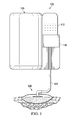
- FIGS. 1-3 illustrate an exemplary embodiment of a system 100 for providing fluid delivery to a wound therapy dressing.
- system 100 includes a housing 105 with a receptacle 130 configured to receive a reservoir 110.
- system 100 further comprises a conduit 125 and a wound dressing 120.
- Conduit 125 may be, for example, a muli-lumen conduit including more than one individual lumen or tube (not shown) housed within conduit 125.
- the individual lumens or tubes within conduit 125 may be in fluid communication with wound dressing 120.
- Each lumen or tube may be utilized for a different purpose, such as, for example, instillation of fluid to wound dressing 120, communication of negative pressure to wound dressing 120, and receipt of negative pressure feedback from wound dressing 120 as described further below.
- Reservoir 110 may be, for example, configured as a polyethylene bag similar to those used for intravenous fluid delivery. Compression of reservoir 110 can exert a positive pressure on fluid in reservoir 110 and force the fluid from reservoir 110 as described in more detail below.
- receptacle 130 comprises a biasing mechanism 136 configured to securely position reservoir 110.
- biasing mechanism 136 is configured to compress reservoir 110 by exerting an external force on reservoir 110.
- housing 105 of system 100 may include a negative pressure source 112, a negative pressure controller 113, a control circuit 114, a flow controller 116 and a flow sensor 118.
- Negative pressure source 112 may be, for example, a vacuum pump.
- Negative pressure controller 113 may be a valve, including for example, a control valve or a manually operated valve.
- Flow controller 116 may also be configured as a valve, including a control valve in certain embodiments.
- housing 105 may be configured to receive reservoir 110.
- receptacle 130 may be moved away from housing 105 in the direction indicated by arrow 131 for insertion of reservoir 110 into receptacle 130 in the direction indicated by arrow 111.
- Receptacle 130 can then be moved toward housing 105 ( e.g., in the direction opposite of arrow 131) so that reservoir 110 is received by housing 105 and in fluid communication with conduit 125, as depicted in FIGS. 1-2 .
- the exemplary embodiment of FIG. 3 depicts receptacle 130 slidably received within housing 105 and configured to extend from housing 105 in a lateral direction for insertion of reservoir 110 into receptacle 130.
- receptacle 130 may be configured to extend from housing 105 in any suitable direction for inserting reservoir 110.
- receptacle 130 may be coupled to housing 105 and stationary relative to housing 105.
- Biasing mechanism 136 is configured to bias reservoir 110 toward housing 105, thereby securing reservoir 110. Extending receptacle 130 from housing 105 as described above reduces the bias from biasing mechanism 136 on reservoir 110 so that a user may more easily insert reservoir 110 into receptacle 130.
- biasing mechanism 136 is configured to compress reservoir 110, thereby exerting a positive pressure on fluid in reservoir 110. The compression of reservoir 110 from biasing mechanism 136 exerts a positive pressure on the fluid in reservoir 110, providing fluid flow from reservoir 110 through conduit 125 without the need for an external pumping mechanism ( e.g ., a peristaltic pump).
- the ability to provide fluid flow from reservoir 110 to wound dressing 120 without a separate pumping mechanism can greatly reduce the complexity of a wound therapy system that provides both negative pressure treatment and fluid instillation. Such a configuration can also reduce the power requirements associated with fluid delivery.
- Biasing mechanism 136 may be configured as a constant-force type spring adapted to deliver a substantially constant mechanical load over a full length of travel of the spring.
- the pressure created by biasing mechanism 136 in reservoir 110 may reduce the potential for inconsistencies in fluid flow experienced by system 100 caused by, for example, height differences between wound dressing 120 and reservoir 110.
- biasing mechanism 136 may exert a substantially constant pressure on reservoir 110 that is greater than the pressure required to hold a static column of instillation fluid to a height approximating the typical distance reservoir 110 may be positioned below wound dressing 120 during use.
- biasing mechanism 136 may exert a substantially constant pressure on reservoir 110 of approximately 75mm Hg, corresponding to the pressure required to hold a static column of instillation fluid to a 1 meter height. In other exemplary embodiments, biasing mechanism 136 may be configured to exert pressure greater than or less than 75mm Hg.
- fluid in conduit 125 is directed through flow sensor 118 and flow controller 116.
- Flow sensor 118 and flow controller 116 are electrically coupled to control circuit 114 and in fluid communication with conduit 125 between fluid reservoir 110 and wound dressing 120.
- Flow sensor 118 can detect the rate and/or volume of fluid flow from reservoir 110 through conduit 125 and provide a corresponding measurement signal, such as a fluid flow rate signal, to control circuit 114.
- control circuit 114 can send a control signal to flow controller 116 to control the flow of fluid through conduit 125 to wound dressing 120.
- control circuit 114 can send a signal to flow controller 116 to reduce the amount of fluid flow to wound dressing 120.
- flow controller 116 may be a control valve adapted to reduce the amount of fluid flow by partial or complete closure of the control valve.
- flow controller 116 may stop fluid flow to wound dressing 120 after a particular volume of fluid has been delivered to wound dressing 120. The volume of fluid may be calculated, for example, based on the fluid flow rate and the length of time of fluid flow.
- FIG. 4 a flow chart is provided to illustrate an exemplary method for operating system 100.
- the order and labeled steps of the method depicted in FIG. 4 are indicative of one non-limiting embodiment.
- the format and symbols employed are understood not to limit the scope of the method, or the order of execution of the steps depicted in the method.
- a method 400 depicted therein includes steps that may be executed for the operation of an exemplary system according to this disclosure, including system 100 of FIGS. 1-3 .
- Certain embodiments may include a tangible computer readable medium comprising computer readable code that, when executed by a computer, causes the computer to perform operations and calculations comprising the steps described herein and depicted in FIG. 4 .
- step 401 represents the start of the therapy cycle.
- Step 402 includes bringing system 100 to a target negative pressure (via negative pressure source 112 and negative pressure controller 113) while inhibiting the instillation fluid flow ( e.g., by maintaining flow controller 116 in the closed position).
- Step 403 includes turning off negative pressure source 112 and/or closing negative pressure controller 113 in system 100 when the target negative pressure has been attained in wound dressing 120.
- Control circuit 114 may be adapted to control negative pressure source 112 for bringing wound dressing 120 up to the target negative pressure, or otherwise regulating the negative pressure in wound dressing 120.
- control circuit 114 may be adapted to receive a negative pressure signal that corresponds to the negative pressure in wound therapy dressing 120.
- Control circuit 114 may control the application of negative pressure from negative pressure source 112 to wound therapy dressing 120 by, for example, sending a signal to negative pressure controller 113 and/or negative pressure source 112 to increase or decrease the negative pressure applied to wound dressing 120 according to the negative pressure signal.
- Control circuit 114 may receive the negative pressure signal from, for example, a negative pressure feedback lumen (not shown) in fluid communication with a pressure sensor (not shown) associated with control circuit 114.
- the negative pressure feedback lumen may be housed within conduit 125, providing a multi-lumen configuration for conduit 125. In other embodiments, the negative pressure feedback lumen may be coupled to wound dressing 120 separate from conduit 125.
- the volumetric leak rate of system 100 and wound dressing 120 can be characterized in step 404, followed by an evaluation of whether the volumetric leak rate is acceptable in step 405. If the volumetric leak rate is not acceptable, the user can address the cause of the leak rate in step 406 and return to step 402 in the method.
- the volumetric leak rate of the negative pressure from wound dressing 120 may be substantially equal to a volumetric flow rate of the negative pressure to wound dressing 120 that is required to maintain the negative pressure in wound dressing 120 substantially at the target negative pressure.
- the volumetric leak rate may be measured, or characterized, by determining a required volumetric flow rate of the negative pressure to wound dressing 120 for maintaining the negative pressure in wound dressing 120 substantially at the target negative pressure.
- the required volumetric flow rate of the negative pressure may be determined, for example, by successively decreasing the volumetric flow rate of the negative pressure to wound dressing 120 as wound dressing 120 approaches the target negative pressure.
- the required volumetric flow rate of the negative pressure to wound dressing 120 is measured when the volumetric flow rate is decreased to a value that maintains wound dressing 120 at the target negative pressure without fluctuation of the negative pressure, i.e., a steady state condition.
- a processor including software that is associated with control circuit 114 may be employed to monitor the negative pressure in wound dressing 120 and the volumetric flow rate of the negative pressure from negative pressure source 112 as wound dressing 120 reaches the steady state condition at the target negative pressure.
- Negative pressure source 112 can then be turned off and/or negative pressure controller 113 closed in step 408, followed by enabling instillation fluid flow in step 409, e.g., by opening a valve in system 100, such as flow controller 116.
- Biasing mechanism 136 can provide sufficient positive pressure on fluid in fluid reservoir 110 to enable instillation fluid flow in step 409 without the use of a separate pumping mechanism as previously described.
- instillation fluid flow may be enabled by operation of the negative pressure in wound dressing 120 drawing fluid from fluid reservoir 110 into wound dressing 120. As fluid from reservoir 110 enters wound dressing 120, the negative pressure in wound dressing 120 gradually approaches or otherwise returns to atmospheric pressure, i.e., the negative pressure decreases.
- biasing mechanism 136 may be omitted.
- system 100 can monitor the volumetric flow rate of the instillation fluid, as well as the negative pressure at wound dressing 120.
- the monitored parameters of system 100 can be evaluated in step 411 to determine, for example, whether an unexpected change in pressure is present, such as the negative pressure at wound dressing 120 returning to atmospheric pressure sooner than expected based on the previously-measured volumetric leak rate. If the pressure change is not acceptable, the instillation fluid flow can be discontinued in step 412 and operation of system 100 can be terminated in step 413.
- system 100 can verify that the pressure has reached atmospheric pressure in step 414.
- System 100 may then stop the flow of instillation fluid in step 415 (e.g., by closing flow controller 116 in the instillation fluid flow path) and allow the wound to soak for a predetermined time period.
- the predetermined time period may be any suitable time period determined by a clinician as appropriate for the circumstances.
- system 100 can store the instilled volume for clinical reference and monitor the wound reduction. The wound reduction, or healing of the wound, may reduce the total volume of fluid instilled into wound dressing 120 by the method described above.
- the method may include the step of applying negative pressure to wound dressing 120 while the fluid from reservoir 110 flows into wound dressing 120.
- the flow rate of the negative pressure applied while the fluid flows into wound dressing 120 may substantially correspond to the previously-measured volumetric leak rate of the negative pressure from wound dressing 120.
- system 100 can enhance the accuracy of the volume of the fluid from reservoir 110 drawn into wound dressing 120 by operation of the negative pressure in wound dressing 120, i.e., the decreasing negative pressure in wound dressing 120 corresponds substantially to the fluid from reservoir 120 being instilled into wound dressing 120 rather than leakage of the negative pressure from wound dressing 120.
- System 100 can then determine if the soak time is complete in step 417. If the soak time is not complete, system 100 can continue to soak the wound as described in step 415. If the soak time is determined to be complete, system 100 can recover fluid in step 418 ( e.g. by operating the negative pressure source 112 and opening negative pressure controller 113 to apply negative pressure to wound dressing 120). The cycle can then be completed in step 419 and system 100 can be powered off.
- the method may include determining a total volume of the fluid flow from reservoir 110 into wound dressing 120.
- the total volume of the fluid flow may substantially correspond to the flow rate of the fluid into wound dressing 120 and a time period required for wound dressing 120 to reach approximately atmospheric pressure after enabling the fluid flow to wound dressing 120.
- variations in the total volume of fluid instilled into wound dressing 120 may be logged and compared to one another to indicate a rate of healing or reduction for the particular wound.
Landscapes
- Health & Medical Sciences (AREA)
- Heart & Thoracic Surgery (AREA)
- Life Sciences & Earth Sciences (AREA)
- Public Health (AREA)
- Anesthesiology (AREA)
- Biomedical Technology (AREA)
- Veterinary Medicine (AREA)
- Hematology (AREA)
- Engineering & Computer Science (AREA)
- Animal Behavior & Ethology (AREA)
- General Health & Medical Sciences (AREA)
- Vascular Medicine (AREA)
- Oral & Maxillofacial Surgery (AREA)
- Pulmonology (AREA)
- Surgery (AREA)
- Physics & Mathematics (AREA)
- Fluid Mechanics (AREA)
- Media Introduction/Drainage Providing Device (AREA)
- External Artificial Organs (AREA)
Applications Claiming Priority (3)
| Application Number | Priority Date | Filing Date | Title |
|---|---|---|---|
| US201261594033P | 2012-02-02 | 2012-02-02 | |
| EP13703687.7A EP2809372B1 (fr) | 2012-02-02 | 2013-01-28 | Systèmes et procédés permettant de distribuer un fluide dans le cadre du traitement de plaies par un pansement |
| PCT/US2013/023482 WO2013116158A2 (fr) | 2012-02-02 | 2013-01-28 | Systèmes et procédés permettant de distribuer un fluide dans le cadre du traitement de plaies par un pansement |
Related Parent Applications (1)
| Application Number | Title | Priority Date | Filing Date |
|---|---|---|---|
| EP13703687.7A Division EP2809372B1 (fr) | 2012-02-02 | 2013-01-28 | Systèmes et procédés permettant de distribuer un fluide dans le cadre du traitement de plaies par un pansement |
Publications (2)
| Publication Number | Publication Date |
|---|---|
| EP3095473A1 true EP3095473A1 (fr) | 2016-11-23 |
| EP3095473B1 EP3095473B1 (fr) | 2021-03-03 |
Family
ID=47684049
Family Applications (2)
| Application Number | Title | Priority Date | Filing Date |
|---|---|---|---|
| EP13703687.7A Active EP2809372B1 (fr) | 2012-02-02 | 2013-01-28 | Systèmes et procédés permettant de distribuer un fluide dans le cadre du traitement de plaies par un pansement |
| EP16177808.9A Active EP3095473B1 (fr) | 2012-02-02 | 2013-01-28 | Systèmes permettant de distribuer un fluide dans le cadre du traitement de plaies par un pansement |
Family Applications Before (1)
| Application Number | Title | Priority Date | Filing Date |
|---|---|---|---|
| EP13703687.7A Active EP2809372B1 (fr) | 2012-02-02 | 2013-01-28 | Systèmes et procédés permettant de distribuer un fluide dans le cadre du traitement de plaies par un pansement |
Country Status (8)
| Country | Link |
|---|---|
| US (3) | US8992494B2 (fr) |
| EP (2) | EP2809372B1 (fr) |
| JP (2) | JP6369865B2 (fr) |
| CN (1) | CN104066461B (fr) |
| AU (2) | AU2013215380B2 (fr) |
| CA (1) | CA2857971C (fr) |
| HK (1) | HK1203862A1 (fr) |
| WO (1) | WO2013116158A2 (fr) |
Families Citing this family (27)
| Publication number | Priority date | Publication date | Assignee | Title |
|---|---|---|---|---|
| EP2441409A1 (fr) | 2010-10-12 | 2012-04-18 | Smith&Nephew, Inc. | Dispositif médical |
| JP6333862B2 (ja) * | 2013-02-23 | 2018-05-30 | アスパイア・バリアトリックス・インコーポレーテッド | 胃から物質を排出するための装置および方法 |
| CN105492035B (zh) | 2013-03-14 | 2019-06-14 | 史密夫和内修有限公司 | 用于应用减压治疗的系统和方法 |
| US9737649B2 (en) | 2013-03-14 | 2017-08-22 | Smith & Nephew, Inc. | Systems and methods for applying reduced pressure therapy |
| EP3033119B1 (fr) | 2013-08-13 | 2023-10-11 | Smith & Nephew, Inc. | Systèmes pour appliquer une thérapie à pression réduite |
| EP3082893B8 (fr) | 2013-12-18 | 2017-09-13 | KCI Licensing, Inc. | Système d'instillation de fluide autonome à surveillance de pression de région de tissu |
| US10004884B2 (en) * | 2014-03-19 | 2018-06-26 | University Of Washington | Negative pressure wound treatment system |
| EP3659638B1 (fr) | 2014-07-31 | 2026-01-07 | Smith & Nephew, Inc. | Systèmes et procédés pour la mise en uvre d'une thérapie par pression réduite |
| US12133789B2 (en) | 2014-07-31 | 2024-11-05 | Smith & Nephew, Inc. | Reduced pressure therapy apparatus construction and control |
| CN104174111A (zh) * | 2014-09-11 | 2014-12-03 | 昆山韦睿医疗科技有限公司 | 负压伤口治疗设备及其控制方法 |
| DE102015110432A1 (de) | 2015-06-29 | 2016-12-29 | Paul Hartmann Ag | Instillationsadapter für ein Unterdruckwundbehandlungssystem |
| CN105597166B (zh) * | 2016-02-01 | 2017-12-15 | 中国人民解放军第三军医大学野战外科研究所 | 一种渐变式负压吸引方法和基于该方法的治疗装置 |
| EP3413945B1 (fr) | 2016-02-12 | 2024-04-24 | Smith & Nephew, Inc. | Systèmes et procédés de détection de conditions opérationnelles de pressothérapie par pression réduite |
| JP6975172B2 (ja) | 2016-05-03 | 2021-12-01 | スミス アンド ネフュー ピーエルシーSmith & Nephew Public Limited Company | 陰圧療法システムにおける陰圧源を駆動するためのシステム及び方法 |
| US11602461B2 (en) | 2016-05-13 | 2023-03-14 | Smith & Nephew, Inc. | Automatic wound coupling detection in negative pressure wound therapy systems |
| CN110650755A (zh) | 2017-03-09 | 2020-01-03 | 生物技术秘书部 | 用于联合的负压和流体输送系统的伤口敷料 |
| CN111565769B (zh) | 2017-12-20 | 2022-10-11 | 3M创新知识产权公司 | 用于伤口治疗装置的组合吊架臂延伸部及泵盖 |
| WO2019190993A1 (fr) * | 2018-03-29 | 2019-10-03 | Kci Licensing, Inc. | Système de traitement de plaie permettant une estimation du volume de la plaie |
| EP3773778B1 (fr) | 2018-04-02 | 2025-11-12 | IC Surgical, Inc. | Pompes à pression négative et procédés associés |
| EP3840794B1 (fr) | 2018-08-21 | 2023-10-11 | 3M Innovative Properties Company | Système d'utilisation d'une diminution de pression pour déterminer la capacité de fluide disponible dans un pansement à pression négative |
| WO2020154220A1 (fr) * | 2019-01-25 | 2020-07-30 | Kci Licensing, Inc. | Systèmes et méthodes de purge par instillation |
| CN118403235A (zh) * | 2019-03-27 | 2024-07-30 | 3M创新知识产权公司 | 具有伤口体积估计的伤口治疗系统 |
| JP2022540272A (ja) * | 2019-03-27 | 2022-09-15 | ケーシーアイ ライセンシング インコーポレイテッド | 創傷体積推定を伴う創傷療法システム |
| US11426506B2 (en) | 2019-03-27 | 2022-08-30 | Kci Licensing, Inc. | Wound therapy system with wound volume estimation |
| WO2020227258A1 (fr) * | 2019-05-07 | 2020-11-12 | Kci Licensing, Inc. | Système de thérapie de plaie par pression négative ayant une distribution de fluide dynamique |
| GB202002338D0 (en) * | 2020-02-20 | 2020-04-08 | Convatec Ltd | A method and control system for a wound therapy apparatus |
| WO2021178568A1 (fr) * | 2020-03-03 | 2021-09-10 | Deroyal Industries, Inc. | Système d'instillation de thérapie de plaie par pression négative |
Citations (5)
| Publication number | Priority date | Publication date | Assignee | Title |
|---|---|---|---|---|
| WO2000078372A1 (fr) * | 1999-06-18 | 2000-12-28 | Alcon Laboratories, Inc. | Systeme de regulation de perfusion |
| US20030236488A1 (en) * | 2002-06-24 | 2003-12-25 | Pavel Novak | Apparatus for irrigating a body cavity with a liquid |
| EP1900347A1 (fr) * | 2006-09-14 | 2008-03-19 | Alcon, Inc. | Procédé pour le contrôle d'un système d'aspiration/irrigation |
| WO2008098207A2 (fr) * | 2007-02-09 | 2008-08-14 | Twin Star Medical, Inc. | Procédé et système pour l'utilisation de cathéters à fibres creuses dans des applications topiques |
| DE102009025003A1 (de) * | 2009-06-16 | 2010-12-23 | Vcs Medical Technology Gmbh | Verfahren zum Betreiben eines therapeutischen Geräts zur Förderung der Wundheilung |
Family Cites Families (139)
| Publication number | Priority date | Publication date | Assignee | Title |
|---|---|---|---|---|
| US1355846A (en) | 1920-02-06 | 1920-10-19 | David A Rannells | Medical appliance |
| US2547758A (en) | 1949-01-05 | 1951-04-03 | Wilmer B Keeling | Instrument for treating the male urethra |
| US2632443A (en) | 1949-04-18 | 1953-03-24 | Eleanor P Lesher | Surgical dressing |
| GB692578A (en) | 1949-09-13 | 1953-06-10 | Minnesota Mining & Mfg | Improvements in or relating to drape sheets for surgical use |
| US2682873A (en) | 1952-07-30 | 1954-07-06 | Johnson & Johnson | General purpose protective dressing |
| NL189176B (nl) | 1956-07-13 | 1900-01-01 | Hisamitsu Pharmaceutical Co | Pleister op basis van een synthetische rubber. |
| US2969057A (en) | 1957-11-04 | 1961-01-24 | Brady Co W H | Nematodic swab |
| US3066672A (en) | 1960-09-27 | 1962-12-04 | Jr William H Crosby | Method and apparatus for serial sampling of intestinal juice |
| US3367332A (en) | 1965-08-27 | 1968-02-06 | Gen Electric | Product and process for establishing a sterile area of skin |
| US3520300A (en) | 1967-03-15 | 1970-07-14 | Amp Inc | Surgical sponge and suction device |
| US3568675A (en) | 1968-08-30 | 1971-03-09 | Clyde B Harvey | Fistula and penetrating wound dressing |
| US3682180A (en) | 1970-06-08 | 1972-08-08 | Coilform Co Inc | Drain clip for surgical drain |
| BE789293Q (fr) | 1970-12-07 | 1973-01-15 | Parke Davis & Co | Pansement medico-chirugical pour brulures et lesions analogues |
| US3826254A (en) | 1973-02-26 | 1974-07-30 | Verco Ind | Needle or catheter retaining appliance |
| US3989169A (en) * | 1975-06-13 | 1976-11-02 | Betz Laboratories, Inc. | Automatic self-leveling fluid dispenser |
| DE2527706A1 (de) | 1975-06-21 | 1976-12-30 | Hanfried Dr Med Weigand | Einrichtung zum einleiten von kontrastmittel in einen kuenstlichen darmausgang |
| DE2640413C3 (de) | 1976-09-08 | 1980-03-27 | Richard Wolf Gmbh, 7134 Knittlingen | Katheter-Überwachungsgerät |
| NL7710909A (nl) | 1976-10-08 | 1978-04-11 | Smith & Nephew | Samengestelde hechtstrook. |
| GB1562244A (en) | 1976-11-11 | 1980-03-05 | Lock P M | Wound dressing materials |
| US4080970A (en) | 1976-11-17 | 1978-03-28 | Miller Thomas J | Post-operative combination dressing and internal drain tube with external shield and tube connector |
| US4139004A (en) | 1977-02-17 | 1979-02-13 | Gonzalez Jr Harry | Bandage apparatus for treating burns |
| US4184510A (en) | 1977-03-15 | 1980-01-22 | Fibra-Sonics, Inc. | Valued device for controlling vacuum in surgery |
| US4165748A (en) | 1977-11-07 | 1979-08-28 | Johnson Melissa C | Catheter tube holder |
| US4245637A (en) | 1978-07-10 | 1981-01-20 | Nichols Robert L | Shutoff valve sleeve |
| SE414994B (sv) | 1978-11-28 | 1980-09-01 | Landstingens Inkopscentral | Venkateterforband |
| WO1980001139A1 (fr) | 1978-12-06 | 1980-06-12 | Svedman Paul | Dispositif de traitement des tissus, par exemple de la peau |
| US4266545A (en) | 1979-04-06 | 1981-05-12 | Moss James P | Portable suction device for collecting fluids from a closed wound |
| US4284079A (en) | 1979-06-28 | 1981-08-18 | Adair Edwin Lloyd | Method for applying a male incontinence device |
| US4261363A (en) | 1979-11-09 | 1981-04-14 | C. R. Bard, Inc. | Retention clips for body fluid drains |
| US4569348A (en) | 1980-02-22 | 1986-02-11 | Velcro Usa Inc. | Catheter tube holder strap |
| WO1981002516A1 (fr) | 1980-03-11 | 1981-09-17 | E Schmid | Coussin pour comprimer un element de peau greffe |
| US4297995A (en) | 1980-06-03 | 1981-11-03 | Key Pharmaceuticals, Inc. | Bandage containing attachment post |
| US4333468A (en) | 1980-08-18 | 1982-06-08 | Geist Robert W | Mesentery tube holder apparatus |
| US4465485A (en) | 1981-03-06 | 1984-08-14 | Becton, Dickinson And Company | Suction canister with unitary shut-off valve and filter features |
| US4392853A (en) | 1981-03-16 | 1983-07-12 | Rudolph Muto | Sterile assembly for protecting and fastening an indwelling device |
| US4373519A (en) | 1981-06-26 | 1983-02-15 | Minnesota Mining And Manufacturing Company | Composite wound dressing |
| US4392858A (en) | 1981-07-16 | 1983-07-12 | Sherwood Medical Company | Wound drainage device |
| US4419097A (en) | 1981-07-31 | 1983-12-06 | Rexar Industries, Inc. | Attachment for catheter tube |
| AU550575B2 (en) | 1981-08-07 | 1986-03-27 | Richard Christian Wright | Wound drainage device |
| SE429197B (sv) | 1981-10-14 | 1983-08-22 | Frese Nielsen | Anordning for behandling av sar |
| DE3146266A1 (de) | 1981-11-21 | 1983-06-01 | B. Braun Melsungen Ag, 3508 Melsungen | Kombinierte vorrichtung fuer eine medizinische saugdrainage |
| US4551139A (en) | 1982-02-08 | 1985-11-05 | Marion Laboratories, Inc. | Method and apparatus for burn wound treatment |
| US4475909A (en) | 1982-05-06 | 1984-10-09 | Eisenberg Melvin I | Male urinary device and method for applying the device |
| DE3361779D1 (en) | 1982-07-06 | 1986-02-20 | Dow Corning | Medical-surgical dressing and a process for the production thereof |
| NZ206837A (en) | 1983-01-27 | 1986-08-08 | Johnson & Johnson Prod Inc | Thin film adhesive dressing:backing material in three sections |
| US4548202A (en) | 1983-06-20 | 1985-10-22 | Ethicon, Inc. | Mesh tissue fasteners |
| US4540412A (en) | 1983-07-14 | 1985-09-10 | The Kendall Company | Device for moist heat therapy |
| US4543100A (en) | 1983-11-01 | 1985-09-24 | Brodsky Stuart A | Catheter and drain tube retainer |
| US4525374A (en) | 1984-02-27 | 1985-06-25 | Manresa, Inc. | Treating hydrophobic filters to render them hydrophilic |
| CA1286177C (fr) | 1984-05-03 | 1991-07-16 | Smith And Nephew Associated Companies Plc | Pansement adhesif |
| US4897081A (en) | 1984-05-25 | 1990-01-30 | Thermedics Inc. | Percutaneous access device |
| US5215522A (en) | 1984-07-23 | 1993-06-01 | Ballard Medical Products | Single use medical aspirating device and method |
| GB8419745D0 (en) | 1984-08-02 | 1984-09-05 | Smith & Nephew Ass | Wound dressing |
| US4872450A (en) | 1984-08-17 | 1989-10-10 | Austad Eric D | Wound dressing and method of forming same |
| US4655754A (en) | 1984-11-09 | 1987-04-07 | Stryker Corporation | Vacuum wound drainage system and lipids baffle therefor |
| US4826494A (en) | 1984-11-09 | 1989-05-02 | Stryker Corporation | Vacuum wound drainage system |
| US4605399A (en) | 1984-12-04 | 1986-08-12 | Complex, Inc. | Transdermal infusion device |
| US5037397A (en) | 1985-05-03 | 1991-08-06 | Medical Distributors, Inc. | Universal clamp |
| US4640688A (en) | 1985-08-23 | 1987-02-03 | Mentor Corporation | Urine collection catheter |
| US4710165A (en) | 1985-09-16 | 1987-12-01 | Mcneil Charles B | Wearable, variable rate suction/collection device |
| US4758220A (en) | 1985-09-26 | 1988-07-19 | Alcon Laboratories, Inc. | Surgical cassette proximity sensing and latching apparatus |
| US4733659A (en) | 1986-01-17 | 1988-03-29 | Seton Company | Foam bandage |
| WO1987004626A1 (fr) | 1986-01-31 | 1987-08-13 | Osmond, Roger, L., W. | Systeme de succion pour drainage de blessures et drainage gastro-intestinal |
| US4838883A (en) | 1986-03-07 | 1989-06-13 | Nissho Corporation | Urine-collecting device |
| JPS62281965A (ja) | 1986-05-29 | 1987-12-07 | テルモ株式会社 | カテ−テルおよびカテ−テル用固定部材 |
| GB8621884D0 (en) | 1986-09-11 | 1986-10-15 | Bard Ltd | Catheter applicator |
| GB2195255B (en) | 1986-09-30 | 1991-05-01 | Vacutec Uk Limited | Apparatus for vacuum treatment of an epidermal surface |
| US4743232A (en) | 1986-10-06 | 1988-05-10 | The Clinipad Corporation | Package assembly for plastic film bandage |
| DE3634569A1 (de) | 1986-10-10 | 1988-04-21 | Sachse Hans E | Kondomkatheter, ein harnroehrenkatheter zur verhinderung von aufsteigenden infektionen |
| US4773897A (en) * | 1986-11-06 | 1988-09-27 | Storz Instrument Company | Collection container for ophthalmic surgical system |
| JPS63135179A (ja) | 1986-11-26 | 1988-06-07 | 立花 俊郎 | 薬物の経皮投与具 |
| GB8628564D0 (en) | 1986-11-28 | 1987-01-07 | Smiths Industries Plc | Anti-foaming agent suction apparatus |
| GB8706116D0 (en) | 1987-03-14 | 1987-04-15 | Smith & Nephew Ass | Adhesive dressings |
| US4787888A (en) | 1987-06-01 | 1988-11-29 | University Of Connecticut | Disposable piezoelectric polymer bandage for percutaneous delivery of drugs and method for such percutaneous delivery (a) |
| US4863449A (en) | 1987-07-06 | 1989-09-05 | Hollister Incorporated | Adhesive-lined elastic condom cathether |
| US5176663A (en) | 1987-12-02 | 1993-01-05 | Pal Svedman | Dressing having pad with compressibility limiting elements |
| US4906240A (en) | 1988-02-01 | 1990-03-06 | Matrix Medica, Inc. | Adhesive-faced porous absorbent sheet and method of making same |
| US4985019A (en) | 1988-03-11 | 1991-01-15 | Michelson Gary K | X-ray marker |
| GB8812803D0 (en) | 1988-05-28 | 1988-06-29 | Smiths Industries Plc | Medico-surgical containers |
| US4919654A (en) | 1988-08-03 | 1990-04-24 | Kalt Medical Corporation | IV clamp with membrane |
| US5000741A (en) | 1988-08-22 | 1991-03-19 | Kalt Medical Corporation | Transparent tracheostomy tube dressing |
| US5059596A (en) | 1989-01-16 | 1991-10-22 | Roussel Uclaf | Azabicyclo compounds |
| GB8906100D0 (en) | 1989-03-16 | 1989-04-26 | Smith & Nephew | Laminates |
| US5261893A (en) | 1989-04-03 | 1993-11-16 | Zamierowski David S | Fastening system and method |
| US4969880A (en) | 1989-04-03 | 1990-11-13 | Zamierowski David S | Wound dressing and treatment method |
| US5527293A (en) | 1989-04-03 | 1996-06-18 | Kinetic Concepts, Inc. | Fastening system and method |
| US5100396A (en) | 1989-04-03 | 1992-03-31 | Zamierowski David S | Fluidic connection system and method |
| JP2719671B2 (ja) | 1989-07-11 | 1998-02-25 | 日本ゼオン株式会社 | 創傷被覆材 |
| US5358494A (en) | 1989-07-11 | 1994-10-25 | Svedman Paul | Irrigation dressing |
| US5232453A (en) | 1989-07-14 | 1993-08-03 | E. R. Squibb & Sons, Inc. | Catheter holder |
| GB2235877A (en) | 1989-09-18 | 1991-03-20 | Antonio Talluri | Closed wound suction apparatus |
| US5134994A (en) | 1990-02-12 | 1992-08-04 | Say Sam L | Field aspirator in a soft pack with externally mounted container |
| US5092858A (en) | 1990-03-20 | 1992-03-03 | Becton, Dickinson And Company | Liquid gelling agent distributor device |
| US5149331A (en) | 1991-05-03 | 1992-09-22 | Ariel Ferdman | Method and device for wound closure |
| US5278100A (en) | 1991-11-08 | 1994-01-11 | Micron Technology, Inc. | Chemical vapor deposition technique for depositing titanium silicide on semiconductor wafers |
| US5636643A (en) | 1991-11-14 | 1997-06-10 | Wake Forest University | Wound treatment employing reduced pressure |
| US5645081A (en) | 1991-11-14 | 1997-07-08 | Wake Forest University | Method of treating tissue damage and apparatus for same |
| US5279550A (en) | 1991-12-19 | 1994-01-18 | Gish Biomedical, Inc. | Orthopedic autotransfusion system |
| US5167613A (en) | 1992-03-23 | 1992-12-01 | The Kendall Company | Composite vented wound dressing |
| FR2690617B1 (fr) | 1992-04-29 | 1994-06-24 | Cbh Textile | Pansement adhesif transparent. |
| DE4306478A1 (de) | 1993-03-02 | 1994-09-08 | Wolfgang Dr Wagner | Drainagevorrichtung, insbesondere Pleuradrainagevorrichtung, und Drainageverfahren |
| US5342376A (en) | 1993-05-03 | 1994-08-30 | Dermagraphics, Inc. | Inserting device for a barbed tissue connector |
| US6241747B1 (en) | 1993-05-03 | 2001-06-05 | Quill Medical, Inc. | Barbed Bodily tissue connector |
| US5344415A (en) | 1993-06-15 | 1994-09-06 | Deroyal Industries, Inc. | Sterile system for dressing vascular access site |
| US5437651A (en) | 1993-09-01 | 1995-08-01 | Research Medical, Inc. | Medical suction apparatus |
| US5549584A (en) | 1994-02-14 | 1996-08-27 | The Kendall Company | Apparatus for removing fluid from a wound |
| US5556375A (en) | 1994-06-16 | 1996-09-17 | Hercules Incorporated | Wound dressing having a fenestrated base layer |
| US5607388A (en) | 1994-06-16 | 1997-03-04 | Hercules Incorporated | Multi-purpose wound dressing |
| US5664270A (en) | 1994-07-19 | 1997-09-09 | Kinetic Concepts, Inc. | Patient interface system |
| ATE172377T1 (de) | 1994-08-22 | 1998-11-15 | Kinetic Concepts Inc | Wunddrainagevorrichtung |
| DE29504378U1 (de) | 1995-03-15 | 1995-09-14 | MTG Medizinisch, technische Gerätebau GmbH, 66299 Friedrichsthal | Elektronisch geregelte Niedervakuumpumpe für die Thorax- und Wunddrainage |
| US5800383A (en) * | 1996-07-17 | 1998-09-01 | Aquarius Medical Corporation | Fluid management system for arthroscopic surgery |
| GB9523253D0 (en) | 1995-11-14 | 1996-01-17 | Mediscus Prod Ltd | Portable wound treatment apparatus |
| US6135116A (en) | 1997-07-28 | 2000-10-24 | Kci Licensing, Inc. | Therapeutic method for treating ulcers |
| GB9719520D0 (en) | 1997-09-12 | 1997-11-19 | Kci Medical Ltd | Surgical drape and suction heads for wound treatment |
| AU755496B2 (en) | 1997-09-12 | 2002-12-12 | Kci Licensing, Inc. | Surgical drape and suction head for wound treatment |
| US6071267A (en) | 1998-02-06 | 2000-06-06 | Kinetic Concepts, Inc. | Medical patient fluid management interface system and method |
| US6488643B1 (en) | 1998-10-08 | 2002-12-03 | Kci Licensing, Inc. | Wound healing foot wrap |
| US6287316B1 (en) | 1999-03-26 | 2001-09-11 | Ethicon, Inc. | Knitted surgical mesh |
| US6856821B2 (en) | 2000-05-26 | 2005-02-15 | Kci Licensing, Inc. | System for combined transcutaneous blood gas monitoring and vacuum assisted wound closure |
| US7799004B2 (en) | 2001-03-05 | 2010-09-21 | Kci Licensing, Inc. | Negative pressure wound treatment apparatus and infection identification system and method |
| US6991643B2 (en) | 2000-12-20 | 2006-01-31 | Usgi Medical Inc. | Multi-barbed device for retaining tissue in apposition and methods of use |
| CA2389981A1 (fr) | 1999-11-05 | 2001-05-10 | Tandem Medical, Inc. | Appareil de transport de medicaments et methodes d'infusion intraveineuse |
| US6764462B2 (en) * | 2000-11-29 | 2004-07-20 | Hill-Rom Services Inc. | Wound treatment apparatus |
| DE60039451D1 (de) | 1999-11-29 | 2008-08-21 | Hill Rom Services Inc | Vorrichtung zur behandlung einer wunde |
| US6824533B2 (en) * | 2000-11-29 | 2004-11-30 | Hill-Rom Services, Inc. | Wound treatment apparatus |
| CA2400895C (fr) | 2000-02-24 | 2011-09-13 | Venetec International, Inc. | Systeme polyvalent servant a fixer un catheter |
| US6540705B2 (en) | 2001-02-22 | 2003-04-01 | Core Products International, Inc. | Ankle brace providing upper and lower ankle adjustment |
| US7625362B2 (en) * | 2003-09-16 | 2009-12-01 | Boehringer Technologies, L.P. | Apparatus and method for suction-assisted wound healing |
| GB0224986D0 (en) * | 2002-10-28 | 2002-12-04 | Smith & Nephew | Apparatus |
| GB0409443D0 (en) * | 2004-04-28 | 2004-06-02 | Smith & Nephew | Apparatus |
| US7455681B2 (en) * | 2004-09-13 | 2008-11-25 | Wound Care Technologies, Llc | Wound closure product |
| US7837673B2 (en) * | 2005-08-08 | 2010-11-23 | Innovative Therapies, Inc. | Wound irrigation device |
| EP2010245B1 (fr) * | 2005-11-21 | 2015-10-14 | Joshua David Smith | Systeme de soin des plaies |
| NZ576472A (en) * | 2006-09-26 | 2011-12-22 | Boehringer Technologies Lp | Pump system for negative pressure wound therapy |
| US20100022990A1 (en) | 2008-07-25 | 2010-01-28 | Boehringer Technologies, L.P. | Pump system for negative pressure wound therapy and improvements thereon |
| WO2010039481A1 (fr) * | 2008-10-03 | 2010-04-08 | Kci Licensing, Inc. | Système et procédé destinés à utiliser des systèmes micro-électromécaniques (mems) pour guérir des blessures |
| US20110196321A1 (en) * | 2009-06-10 | 2011-08-11 | Tyco Healthcare Group Lp | Fluid Collection Canister Including Canister Top with Filter Membrane and Negative Pressure Wound Therapy Systems Including Same |
| US20110306941A1 (en) | 2010-06-14 | 2011-12-15 | Chandrasekar N R | Portable Lavage Apparatus |
-
2013
- 2013-01-28 HK HK15104536.6A patent/HK1203862A1/xx unknown
- 2013-01-28 JP JP2014555608A patent/JP6369865B2/ja active Active
- 2013-01-28 EP EP13703687.7A patent/EP2809372B1/fr active Active
- 2013-01-28 CN CN201380006134.8A patent/CN104066461B/zh active Active
- 2013-01-28 WO PCT/US2013/023482 patent/WO2013116158A2/fr not_active Ceased
- 2013-01-28 EP EP16177808.9A patent/EP3095473B1/fr active Active
- 2013-01-28 AU AU2013215380A patent/AU2013215380B2/en active Active
- 2013-01-28 CA CA2857971A patent/CA2857971C/fr active Active
- 2013-01-28 US US13/752,180 patent/US8992494B2/en active Active
-
2015
- 2015-03-12 US US14/656,458 patent/US9789234B2/en active Active
-
2017
- 2017-09-12 US US15/701,603 patent/US20180055977A1/en not_active Abandoned
- 2017-11-01 AU AU2017254890A patent/AU2017254890B9/en active Active
-
2018
- 2018-07-04 JP JP2018127228A patent/JP6745845B2/ja active Active
Patent Citations (5)
| Publication number | Priority date | Publication date | Assignee | Title |
|---|---|---|---|---|
| WO2000078372A1 (fr) * | 1999-06-18 | 2000-12-28 | Alcon Laboratories, Inc. | Systeme de regulation de perfusion |
| US20030236488A1 (en) * | 2002-06-24 | 2003-12-25 | Pavel Novak | Apparatus for irrigating a body cavity with a liquid |
| EP1900347A1 (fr) * | 2006-09-14 | 2008-03-19 | Alcon, Inc. | Procédé pour le contrôle d'un système d'aspiration/irrigation |
| WO2008098207A2 (fr) * | 2007-02-09 | 2008-08-14 | Twin Star Medical, Inc. | Procédé et système pour l'utilisation de cathéters à fibres creuses dans des applications topiques |
| DE102009025003A1 (de) * | 2009-06-16 | 2010-12-23 | Vcs Medical Technology Gmbh | Verfahren zum Betreiben eines therapeutischen Geräts zur Förderung der Wundheilung |
Also Published As
| Publication number | Publication date |
|---|---|
| AU2013215380B2 (en) | 2017-09-28 |
| US20180055977A1 (en) | 2018-03-01 |
| JP2018187411A (ja) | 2018-11-29 |
| WO2013116158A2 (fr) | 2013-08-08 |
| US9789234B2 (en) | 2017-10-17 |
| CN104066461B (zh) | 2018-04-03 |
| AU2017254890B9 (en) | 2019-08-08 |
| CA2857971A1 (fr) | 2013-08-08 |
| EP3095473B1 (fr) | 2021-03-03 |
| CA2857971C (fr) | 2022-08-02 |
| JP6369865B2 (ja) | 2018-08-08 |
| AU2017254890B2 (en) | 2019-07-18 |
| EP2809372A2 (fr) | 2014-12-10 |
| HK1203862A1 (en) | 2015-11-06 |
| AU2013215380A1 (en) | 2014-06-05 |
| US8992494B2 (en) | 2015-03-31 |
| CN104066461A (zh) | 2014-09-24 |
| EP2809372B1 (fr) | 2016-07-20 |
| US20130204210A1 (en) | 2013-08-08 |
| JP2015505508A (ja) | 2015-02-23 |
| WO2013116158A3 (fr) | 2013-11-28 |
| AU2017254890A1 (en) | 2017-11-23 |
| JP6745845B2 (ja) | 2020-08-26 |
| US20150224239A1 (en) | 2015-08-13 |
Similar Documents
| Publication | Publication Date | Title |
|---|---|---|
| AU2017254890B9 (en) | Systems and methods for delivering fluid to a wound therapy dressing | |
| US10792482B2 (en) | Systems and methods for delivering fluid to a wound therapy dressing | |
| US20210196871A1 (en) | Systems and methods for delivering fluid to a wound therapy dressing |
Legal Events
| Date | Code | Title | Description |
|---|---|---|---|
| PUAI | Public reference made under article 153(3) epc to a published international application that has entered the european phase |
Free format text: ORIGINAL CODE: 0009012 |
|
| AC | Divisional application: reference to earlier application |
Ref document number: 2809372 Country of ref document: EP Kind code of ref document: P |
|
| AK | Designated contracting states |
Kind code of ref document: A1 Designated state(s): AL AT BE BG CH CY CZ DE DK EE ES FI FR GB GR HR HU IE IS IT LI LT LU LV MC MK MT NL NO PL PT RO RS SE SI SK SM TR |
|
| RAP1 | Party data changed (applicant data changed or rights of an application transferred) |
Owner name: KCI LICENSING, INC. |
|
| STAA | Information on the status of an ep patent application or granted ep patent |
Free format text: STATUS: REQUEST FOR EXAMINATION WAS MADE |
|
| 17P | Request for examination filed |
Effective date: 20170523 |
|
| RBV | Designated contracting states (corrected) |
Designated state(s): AL AT BE BG CH CY CZ DE DK EE ES FI FR GB GR HR HU IE IS IT LI LT LU LV MC MK MT NL NO PL PT RO RS SE SI SK SM TR |
|
| RAP1 | Party data changed (applicant data changed or rights of an application transferred) |
Owner name: KCI LICENSING, INC. |
|
| GRAP | Despatch of communication of intention to grant a patent |
Free format text: ORIGINAL CODE: EPIDOSNIGR1 |
|
| STAA | Information on the status of an ep patent application or granted ep patent |
Free format text: STATUS: GRANT OF PATENT IS INTENDED |
|
| INTG | Intention to grant announced |
Effective date: 20200924 |
|
| RAP1 | Party data changed (applicant data changed or rights of an application transferred) |
Owner name: 3M INNOVATIVE PROPERTIES COMPANY |
|
| GRAS | Grant fee paid |
Free format text: ORIGINAL CODE: EPIDOSNIGR3 |
|
| GRAA | (expected) grant |
Free format text: ORIGINAL CODE: 0009210 |
|
| STAA | Information on the status of an ep patent application or granted ep patent |
Free format text: STATUS: THE PATENT HAS BEEN GRANTED |
|
| AC | Divisional application: reference to earlier application |
Ref document number: 2809372 Country of ref document: EP Kind code of ref document: P |
|
| AK | Designated contracting states |
Kind code of ref document: B1 Designated state(s): AL AT BE BG CH CY CZ DE DK EE ES FI FR GB GR HR HU IE IS IT LI LT LU LV MC MK MT NL NO PL PT RO RS SE SI SK SM TR |
|
| REG | Reference to a national code |
Ref country code: GB Ref legal event code: FG4D |
|
| REG | Reference to a national code |
Ref country code: AT Ref legal event code: REF Ref document number: 1366510 Country of ref document: AT Kind code of ref document: T Effective date: 20210315 Ref country code: CH Ref legal event code: EP |
|
| REG | Reference to a national code |
Ref country code: DE Ref legal event code: R096 Ref document number: 602013076096 Country of ref document: DE |
|
| REG | Reference to a national code |
Ref country code: IE Ref legal event code: FG4D |
|
| REG | Reference to a national code |
Ref country code: LT Ref legal event code: MG9D |
|
| PG25 | Lapsed in a contracting state [announced via postgrant information from national office to epo] |
Ref country code: NO Free format text: LAPSE BECAUSE OF FAILURE TO SUBMIT A TRANSLATION OF THE DESCRIPTION OR TO PAY THE FEE WITHIN THE PRESCRIBED TIME-LIMIT Effective date: 20210603 Ref country code: BG Free format text: LAPSE BECAUSE OF FAILURE TO SUBMIT A TRANSLATION OF THE DESCRIPTION OR TO PAY THE FEE WITHIN THE PRESCRIBED TIME-LIMIT Effective date: 20210603 Ref country code: HR Free format text: LAPSE BECAUSE OF FAILURE TO SUBMIT A TRANSLATION OF THE DESCRIPTION OR TO PAY THE FEE WITHIN THE PRESCRIBED TIME-LIMIT Effective date: 20210303 Ref country code: FI Free format text: LAPSE BECAUSE OF FAILURE TO SUBMIT A TRANSLATION OF THE DESCRIPTION OR TO PAY THE FEE WITHIN THE PRESCRIBED TIME-LIMIT Effective date: 20210303 Ref country code: GR Free format text: LAPSE BECAUSE OF FAILURE TO SUBMIT A TRANSLATION OF THE DESCRIPTION OR TO PAY THE FEE WITHIN THE PRESCRIBED TIME-LIMIT Effective date: 20210604 Ref country code: LT Free format text: LAPSE BECAUSE OF FAILURE TO SUBMIT A TRANSLATION OF THE DESCRIPTION OR TO PAY THE FEE WITHIN THE PRESCRIBED TIME-LIMIT Effective date: 20210303 |
|
| REG | Reference to a national code |
Ref country code: NL Ref legal event code: MP Effective date: 20210303 |
|
| REG | Reference to a national code |
Ref country code: AT Ref legal event code: MK05 Ref document number: 1366510 Country of ref document: AT Kind code of ref document: T Effective date: 20210303 |
|
| PG25 | Lapsed in a contracting state [announced via postgrant information from national office to epo] |
Ref country code: SE Free format text: LAPSE BECAUSE OF FAILURE TO SUBMIT A TRANSLATION OF THE DESCRIPTION OR TO PAY THE FEE WITHIN THE PRESCRIBED TIME-LIMIT Effective date: 20210303 Ref country code: RS Free format text: LAPSE BECAUSE OF FAILURE TO SUBMIT A TRANSLATION OF THE DESCRIPTION OR TO PAY THE FEE WITHIN THE PRESCRIBED TIME-LIMIT Effective date: 20210303 Ref country code: LV Free format text: LAPSE BECAUSE OF FAILURE TO SUBMIT A TRANSLATION OF THE DESCRIPTION OR TO PAY THE FEE WITHIN THE PRESCRIBED TIME-LIMIT Effective date: 20210303 Ref country code: PL Free format text: LAPSE BECAUSE OF FAILURE TO SUBMIT A TRANSLATION OF THE DESCRIPTION OR TO PAY THE FEE WITHIN THE PRESCRIBED TIME-LIMIT Effective date: 20210303 |
|
| PG25 | Lapsed in a contracting state [announced via postgrant information from national office to epo] |
Ref country code: NL Free format text: LAPSE BECAUSE OF FAILURE TO SUBMIT A TRANSLATION OF THE DESCRIPTION OR TO PAY THE FEE WITHIN THE PRESCRIBED TIME-LIMIT Effective date: 20210303 |
|
| PG25 | Lapsed in a contracting state [announced via postgrant information from national office to epo] |
Ref country code: EE Free format text: LAPSE BECAUSE OF FAILURE TO SUBMIT A TRANSLATION OF THE DESCRIPTION OR TO PAY THE FEE WITHIN THE PRESCRIBED TIME-LIMIT Effective date: 20210303 Ref country code: CZ Free format text: LAPSE BECAUSE OF FAILURE TO SUBMIT A TRANSLATION OF THE DESCRIPTION OR TO PAY THE FEE WITHIN THE PRESCRIBED TIME-LIMIT Effective date: 20210303 Ref country code: AT Free format text: LAPSE BECAUSE OF FAILURE TO SUBMIT A TRANSLATION OF THE DESCRIPTION OR TO PAY THE FEE WITHIN THE PRESCRIBED TIME-LIMIT Effective date: 20210303 Ref country code: SM Free format text: LAPSE BECAUSE OF FAILURE TO SUBMIT A TRANSLATION OF THE DESCRIPTION OR TO PAY THE FEE WITHIN THE PRESCRIBED TIME-LIMIT Effective date: 20210303 |
|
| PG25 | Lapsed in a contracting state [announced via postgrant information from national office to epo] |
Ref country code: PT Free format text: LAPSE BECAUSE OF FAILURE TO SUBMIT A TRANSLATION OF THE DESCRIPTION OR TO PAY THE FEE WITHIN THE PRESCRIBED TIME-LIMIT Effective date: 20210705 Ref country code: ES Free format text: LAPSE BECAUSE OF FAILURE TO SUBMIT A TRANSLATION OF THE DESCRIPTION OR TO PAY THE FEE WITHIN THE PRESCRIBED TIME-LIMIT Effective date: 20210303 Ref country code: SK Free format text: LAPSE BECAUSE OF FAILURE TO SUBMIT A TRANSLATION OF THE DESCRIPTION OR TO PAY THE FEE WITHIN THE PRESCRIBED TIME-LIMIT Effective date: 20210303 Ref country code: RO Free format text: LAPSE BECAUSE OF FAILURE TO SUBMIT A TRANSLATION OF THE DESCRIPTION OR TO PAY THE FEE WITHIN THE PRESCRIBED TIME-LIMIT Effective date: 20210303 Ref country code: IS Free format text: LAPSE BECAUSE OF FAILURE TO SUBMIT A TRANSLATION OF THE DESCRIPTION OR TO PAY THE FEE WITHIN THE PRESCRIBED TIME-LIMIT Effective date: 20210703 |
|
| REG | Reference to a national code |
Ref country code: DE Ref legal event code: R097 Ref document number: 602013076096 Country of ref document: DE |
|
| PLBE | No opposition filed within time limit |
Free format text: ORIGINAL CODE: 0009261 |
|
| STAA | Information on the status of an ep patent application or granted ep patent |
Free format text: STATUS: NO OPPOSITION FILED WITHIN TIME LIMIT |
|
| PG25 | Lapsed in a contracting state [announced via postgrant information from national office to epo] |
Ref country code: AL Free format text: LAPSE BECAUSE OF FAILURE TO SUBMIT A TRANSLATION OF THE DESCRIPTION OR TO PAY THE FEE WITHIN THE PRESCRIBED TIME-LIMIT Effective date: 20210303 Ref country code: DK Free format text: LAPSE BECAUSE OF FAILURE TO SUBMIT A TRANSLATION OF THE DESCRIPTION OR TO PAY THE FEE WITHIN THE PRESCRIBED TIME-LIMIT Effective date: 20210303 |
|
| 26N | No opposition filed |
Effective date: 20211206 |
|
| PG25 | Lapsed in a contracting state [announced via postgrant information from national office to epo] |
Ref country code: SI Free format text: LAPSE BECAUSE OF FAILURE TO SUBMIT A TRANSLATION OF THE DESCRIPTION OR TO PAY THE FEE WITHIN THE PRESCRIBED TIME-LIMIT Effective date: 20210303 |
|
| PG25 | Lapsed in a contracting state [announced via postgrant information from national office to epo] |
Ref country code: IT Free format text: LAPSE BECAUSE OF FAILURE TO SUBMIT A TRANSLATION OF THE DESCRIPTION OR TO PAY THE FEE WITHIN THE PRESCRIBED TIME-LIMIT Effective date: 20210303 |
|
| PG25 | Lapsed in a contracting state [announced via postgrant information from national office to epo] |
Ref country code: IS Free format text: LAPSE BECAUSE OF FAILURE TO SUBMIT A TRANSLATION OF THE DESCRIPTION OR TO PAY THE FEE WITHIN THE PRESCRIBED TIME-LIMIT Effective date: 20210703 |
|
| PG25 | Lapsed in a contracting state [announced via postgrant information from national office to epo] |
Ref country code: MC Free format text: LAPSE BECAUSE OF FAILURE TO SUBMIT A TRANSLATION OF THE DESCRIPTION OR TO PAY THE FEE WITHIN THE PRESCRIBED TIME-LIMIT Effective date: 20210303 |
|
| REG | Reference to a national code |
Ref country code: CH Ref legal event code: PL |
|
| REG | Reference to a national code |
Ref country code: BE Ref legal event code: MM Effective date: 20220131 |
|
| PG25 | Lapsed in a contracting state [announced via postgrant information from national office to epo] |
Ref country code: LU Free format text: LAPSE BECAUSE OF NON-PAYMENT OF DUE FEES Effective date: 20220128 |
|
| PG25 | Lapsed in a contracting state [announced via postgrant information from national office to epo] |
Ref country code: FR Free format text: LAPSE BECAUSE OF NON-PAYMENT OF DUE FEES Effective date: 20220131 Ref country code: BE Free format text: LAPSE BECAUSE OF NON-PAYMENT OF DUE FEES Effective date: 20220131 |
|
| PG25 | Lapsed in a contracting state [announced via postgrant information from national office to epo] |
Ref country code: LI Free format text: LAPSE BECAUSE OF NON-PAYMENT OF DUE FEES Effective date: 20220131 Ref country code: CH Free format text: LAPSE BECAUSE OF NON-PAYMENT OF DUE FEES Effective date: 20220131 |
|
| PG25 | Lapsed in a contracting state [announced via postgrant information from national office to epo] |
Ref country code: IE Free format text: LAPSE BECAUSE OF NON-PAYMENT OF DUE FEES Effective date: 20220128 |
|
| P01 | Opt-out of the competence of the unified patent court (upc) registered |
Effective date: 20230530 |
|
| REG | Reference to a national code |
Ref country code: GB Ref legal event code: 732E Free format text: REGISTERED BETWEEN 20240208 AND 20240214 |
|
| REG | Reference to a national code |
Ref country code: DE Ref legal event code: R081 Ref document number: 602013076096 Country of ref document: DE Owner name: SOLVENTUM INTELLECTUAL PROPERTIES CO. (N.D.GES, US Free format text: FORMER OWNER: 3M INNOVATIVE PROPERTIES COMPANY, ST. PAUL, MN, US |
|
| PG25 | Lapsed in a contracting state [announced via postgrant information from national office to epo] |
Ref country code: HU Free format text: LAPSE BECAUSE OF FAILURE TO SUBMIT A TRANSLATION OF THE DESCRIPTION OR TO PAY THE FEE WITHIN THE PRESCRIBED TIME-LIMIT; INVALID AB INITIO Effective date: 20130128 |
|
| PG25 | Lapsed in a contracting state [announced via postgrant information from national office to epo] |
Ref country code: MK Free format text: LAPSE BECAUSE OF FAILURE TO SUBMIT A TRANSLATION OF THE DESCRIPTION OR TO PAY THE FEE WITHIN THE PRESCRIBED TIME-LIMIT Effective date: 20210303 Ref country code: CY Free format text: LAPSE BECAUSE OF FAILURE TO SUBMIT A TRANSLATION OF THE DESCRIPTION OR TO PAY THE FEE WITHIN THE PRESCRIBED TIME-LIMIT Effective date: 20210303 |
|
| PG25 | Lapsed in a contracting state [announced via postgrant information from national office to epo] |
Ref country code: MT Free format text: LAPSE BECAUSE OF FAILURE TO SUBMIT A TRANSLATION OF THE DESCRIPTION OR TO PAY THE FEE WITHIN THE PRESCRIBED TIME-LIMIT Effective date: 20210303 |
|
| PG25 | Lapsed in a contracting state [announced via postgrant information from national office to epo] |
Ref country code: TR Free format text: LAPSE BECAUSE OF FAILURE TO SUBMIT A TRANSLATION OF THE DESCRIPTION OR TO PAY THE FEE WITHIN THE PRESCRIBED TIME-LIMIT Effective date: 20210303 |
|
| PGFP | Annual fee paid to national office [announced via postgrant information from national office to epo] |
Ref country code: GB Payment date: 20251217 Year of fee payment: 14 |
|
| PGFP | Annual fee paid to national office [announced via postgrant information from national office to epo] |
Ref country code: DE Payment date: 20251217 Year of fee payment: 14 |