EP3095492A1 - Machoire avant d'une fixation de surete - Google Patents
Machoire avant d'une fixation de surete Download PDFInfo
- Publication number
- EP3095492A1 EP3095492A1 EP16168131.7A EP16168131A EP3095492A1 EP 3095492 A1 EP3095492 A1 EP 3095492A1 EP 16168131 A EP16168131 A EP 16168131A EP 3095492 A1 EP3095492 A1 EP 3095492A1
- Authority
- EP
- European Patent Office
- Prior art keywords
- sole
- tension element
- tension
- sole holder
- front jaw
- Prior art date
- Legal status (The legal status is an assumption and is not a legal conclusion. Google has not performed a legal analysis and makes no representation as to the accuracy of the status listed.)
- Granted
Links
Images


Classifications
-
- A—HUMAN NECESSITIES
- A63—SPORTS; GAMES; AMUSEMENTS
- A63C—SKATES; SKIS; ROLLER SKATES; DESIGN OR LAYOUT OF COURTS, RINKS OR THE LIKE
- A63C9/00—Ski bindings
- A63C9/08—Ski bindings yieldable or self-releasing in the event of an accident, i.e. safety bindings
- A63C9/085—Ski bindings yieldable or self-releasing in the event of an accident, i.e. safety bindings with sole hold-downs, e.g. swingable
- A63C9/08507—Ski bindings yieldable or self-releasing in the event of an accident, i.e. safety bindings with sole hold-downs, e.g. swingable with a plurality of mobile jaws
- A63C9/08521—Ski bindings yieldable or self-releasing in the event of an accident, i.e. safety bindings with sole hold-downs, e.g. swingable with a plurality of mobile jaws pivoting about a vertical axis, e.g. side release
-
- A—HUMAN NECESSITIES
- A63—SPORTS; GAMES; AMUSEMENTS
- A63C—SKATES; SKIS; ROLLER SKATES; DESIGN OR LAYOUT OF COURTS, RINKS OR THE LIKE
- A63C9/00—Ski bindings
- A63C9/08—Ski bindings yieldable or self-releasing in the event of an accident, i.e. safety bindings
- A63C9/085—Ski bindings yieldable or self-releasing in the event of an accident, i.e. safety bindings with sole hold-downs, e.g. swingable
- A63C9/08557—Details of the release mechanism
- A63C9/08571—Details of the release mechanism using axis and lever
-
- A—HUMAN NECESSITIES
- A63—SPORTS; GAMES; AMUSEMENTS
- A63C—SKATES; SKIS; ROLLER SKATES; DESIGN OR LAYOUT OF COURTS, RINKS OR THE LIKE
- A63C9/00—Ski bindings
- A63C9/08—Ski bindings yieldable or self-releasing in the event of an accident, i.e. safety bindings
- A63C9/085—Ski bindings yieldable or self-releasing in the event of an accident, i.e. safety bindings with sole hold-downs, e.g. swingable
- A63C9/08557—Details of the release mechanism
- A63C9/08585—Details of the release mechanism using transverse biasing element
-
- A—HUMAN NECESSITIES
- A63—SPORTS; GAMES; AMUSEMENTS
- A63C—SKATES; SKIS; ROLLER SKATES; DESIGN OR LAYOUT OF COURTS, RINKS OR THE LIKE
- A63C9/00—Ski bindings
- A63C9/08—Ski bindings yieldable or self-releasing in the event of an accident, i.e. safety bindings
- A63C9/0805—Adjustment of the toe or heel holders; Indicators therefor
Definitions
- the invention relates to a front jaw of a safety ski binding with a housing and with two on the housing about vertical axes pivotable sole holders, which cooperate with elements which are arranged between the sole holders in Skiquerides and acted upon by a running in the direction of ski coil compression spring.
- Such a toe is from the EP 1 892 020 A2 known.
- the acted upon by the spring elements are pistons which are displaceably guided in a cylinder-like housing which has a cylinder axis parallel to the ski direction.
- Each sole holder is pivotable about a housing arranged on the vertical vertical axis and formed as a double lever.
- a link path interacting with the sole-remote arm of the respective sole holder, which is divided into two sections by an elevation, the sole holder being held in the release position on one of these sections.
- This known toe has a number of components which rub against each other when triggered, in particular, sliding friction occurs between the spring and the inner sides of the pistons in which the spring is held, between the outer sides of the pistons and the cylindrical housing and between the sole holders and the slide tracks of the piston, so that the release force is affected accordingly, especially at lower spring preload.
- the invention has for its object to make a toe of the type mentioned in such a way that in a simple and compact design, the sliding friction Triggering is significantly reduced and a defined release force is achieved even at a low spring preload.
- the acted upon by the helical compression spring elements are tension members, wherein the one tension member on one sole holder and the other tension member on the other sole holder is articulated, wherein the vertical axes of the sole holder, based on the position of the mounted on the ski front jaw, are arranged in front of the articulation points of the tension elements.
- the toe jaw can be made with a small number of friction causing points on components and it can also be achieved in setting with lower spring preload exact release forces.
- each tension element extends from its point of articulation on one sole holder in the direction of the other sole holder and in each case in the transverse direction.
- the helical compression spring is expediently supported on those end regions of the tension elements which are remote from their respective articulation points.
- the two tension elements are arranged running inside one another, wherein the helical compression spring is positioned in the mutually extending region of the tension elements.
- the vertical axes about which the sole holders are pivotable relative to the housing designed as a bolt or the like mounted on the housing.
- the sole holders have hinged vertical axes.
- the individual components involved are designed and arranged in a special way.
- the one, first tension member has two arms extending in the ski direction, which are connected at one end via a vertically extending, acted upon by the helical compression spring arm and are hinged on the other a sole holder.
- a bolt is further arranged on the sole holder, with which the ends of the arms of the one tension element are connected and against which the sole holder is rotatably arranged.
- a compact embodiment of the front jaw is supported by the fact that the other, second tension element is designed as a pull rod, which extends with a portion between the arms of the first tension element and is surrounded by the helical compression spring.
- the second tension member carries at its end a relation to the first tension member non-rotatably held first spring abutment which is adjustable in the longitudinal direction of the second tension element.
- the second spring abutment for the helical compression spring is arranged on the connecting arm of the first pulling element and passes in a rotationally movable manner by the second pulling element.
- the second traction element is mounted in a special way on the second sole holder, in order to ensure compression of the helical compression spring in a lateral release by the second sole holder.
- the second tension member passes through the second sole holder and has a widened end portion which sits in a recess of the second sole holder with play and can be supported at the bottom of the recess in a lateral release of this sole holder.
- the opening in the sole holder is widened in the direction of the housing interior and to the front in order to allow a slight tilting movement of the tension elements together with the helical compression spring about the pivot point of the first tension element on the first sole holder.
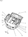
- the figures show a front jaw 1 of a safety ski binding, whose second binding part, a heel-jaw, is not shown. Also not shown is a ski, wherein the designated in the figures with S L dashed line mounted at Safety ski binding given Skilssensachse called, denoted by Q double arrow indicates the transverse direction - parallel to the ski upper side - or the Skiquerides. Indications such as “vertical”, “sideways” and the like relate to the ski mounted toe and a plane parallel to the ski top.
- the toe 1 is provided for receiving the toe-side end of the sole of a ski boot, not shown.
- the safety ski binding exclusively as Abfahrts Kunststoff both the toe 1 and the heel pieces, not shown, are arranged or attached in a conventional manner on the ski.
- an embodiment of the safety ski binding as touring binding is also possible, the toe jaw 1 being arranged on a towing plate likewise not shown, rotatably mounted in the region of the front jaw 1 about a transverse axis, which can be locked on the ski in a detachable manner in its rear region.
- the front jaw 1 has a one-piece or multi-part housing 2 with an upper housing part 2a, a lower housing part 2b and a front housing part 2c.
- the lower housing part 2b has a base plate 3, by means of which the toe 1 can be attached to the ski or on a touring plate in a manner not shown and known per se.
- the base plate 3 may also be a separate component, which is firmly connected to the housing 2, for example screwed.
- Inside the housing 2 are housed components of a triggering mechanism described in detail below.
- the toe 1 has two sole holders, a first sole holder 4 and a second sole holder 5, which are formed at their rear regions in particular in a conventional manner such that they from the top and the front portion of the sole of a ski boot used in the toe 1 overlap at the edge and rest on the side of the sole.
- the sole holders 4, 5 are "one arm" executed and in one embodiment ( Fig. 1 to 3 . Fig. 4 to 7 ) at their front portions 4a, 5a about vertical, for example as a bolt 6a ( Fig. 3 ) executed, arranged on the housing 2 axes 7 to the outside, in the direction of the arrows F 1 and F 2 in Fig. 6 and Fig. 7 , swing out.
- a bolt 6a Fig. 3
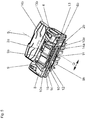
- each sole holder 4, 5 has a support element 4b, 5b which is circular in cross-section concentric with its axis 7, in each case at its region of its front portion 4a, 5a which is concentric with its axis 7, which has a countercurrent surface at one on the lateral edge region of the front part 2c of the housing Support surface 8a, 8b rests.
- the support surfaces 4b, 5b opposite to the support members 4b, 5b formed, more pronounced depressions, so that the support surfaces together with the support elements 4b, 5b form joints about which the sole holder 4, 5 are swung. In this case, no separate axes 7 are required.
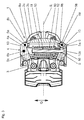
- a first tension element 9, on the second sole holder 5 a second tension member 10 is mounted or articulated.
- the articulation points of the tension elements 9, 10 on the sole holders 4, 5 are located between the axles 7 and the joints 4a, 5b, 8a, 8b and the sections of the sole holders 4, 5 coming into contact with the ski boot.
- Both tension elements 9, 10 extend between the sole holders 4, 5 in the housing interior and in the cross-section Q, that a tension element 10 extends within the other, as will be described.
- the tension element 9 has two arms 9a and 9b extending parallel to the ski upper side and in the ski direction (FIG. Fig. 5 ) and a connecting arm 9c connecting the arms 9a and 9b at one end thereof (FIG. Fig. 5 ), which runs perpendicular to the ski top.
- the second ends of the arms 9a and 9b are connected to a bolt 6b, which is held vertically in the sole holder 4, such that the sole holder 4 is rotatable relative to the pin 6b.
- the connecting arm 9c of the tension element 9 is provided with a through-hole through which the second tension element 10, which is designed as a pull rod in the embodiment shown, protrudes into the interior of the first tension element 9 between the arms 9a and 9b.
- the second tension element 10 is surrounded by a helical compression spring 11, which is supported with its one end via a first spring abutment 12 on the connecting arm 9c.
- the second end of the Helical compression spring 11 is supported on a second spring abutment 13 which is screwed on the end portion of the second tension member 10 and for adjusting the bias of the helical compression spring 11 in the longitudinal direction of the tension element 10 is adjustable.
- the second spring abutment 13 is held relative to the first traction element 9, as shown, for example, by means of two extensions 13a, 13b (FIG. Fig. 2 ) on its outer circumference, which in the longitudinal direction of the arms 9a, 9b of the first pulling element 9 formed openings 14a, 14b ( Fig. 5 ) intervene.
- the second, designed as a pull rod tension member 10 projects beyond the connecting arm 9c of the first tension member 9, passes through an opening 15 in the second sole holder 5 and has an example widened ball-like end portion 10a, which with a certain play in a on the outside of the sole holder 5 in Substantially counter-shaped recess 16 is seated and supported under the pressure of the spring 11 here.
- the opening 15 in the sole holder 5 is designed such that a certain mobility of the tension element 10 in a plane parallel to the ski surface forward is possible and therefore widening starting from the recess 16 in the direction of the housing interior accordingly.
- the end portion 10a is pressed under the action of the helical compression spring 11 against the bottom of the recess 16 so that both sole holders 4, 5 are loaded by the helical compression spring 11.
- the end portion 10a of the tension member 10 is provided with a slot to adjust and change the bias of the helical compression spring 11 in a known manner by means of a conventional tool, in particular a screwdriver.
- a conventional tool in particular a screwdriver.
- the position of the spring abutment 13 changes, so that the projecting through the opening 14a in the upper arm 9a of the tension element 9 extension 13a of the spring abutment 13 can serve as a display element for the selected setting of the bias of the helical compression spring 11.
- a transparent window printed with a scale can be provided in the upper housing part 2a, so that a reading of the set spring preload is possible.
Landscapes
- Footwear And Its Accessory, Manufacturing Method And Apparatuses (AREA)
Applications Claiming Priority (1)
| Application Number | Priority Date | Filing Date | Title |
|---|---|---|---|
| ATA50405/2015A AT517224B1 (de) | 2015-05-18 | 2015-05-18 | Vorderbacken einer Sicherheitsskibindung |
Publications (2)
| Publication Number | Publication Date |
|---|---|
| EP3095492A1 true EP3095492A1 (fr) | 2016-11-23 |
| EP3095492B1 EP3095492B1 (fr) | 2017-12-13 |
Family
ID=55910841
Family Applications (1)
| Application Number | Title | Priority Date | Filing Date |
|---|---|---|---|
| EP16168131.7A Active EP3095492B1 (fr) | 2015-05-18 | 2016-05-03 | Mâchoire avant d'une fixation de sûreté |
Country Status (2)
| Country | Link |
|---|---|
| EP (1) | EP3095492B1 (fr) |
| AT (1) | AT517224B1 (fr) |
Cited By (1)
| Publication number | Priority date | Publication date | Assignee | Title |
|---|---|---|---|---|
| AT526522A4 (de) * | 2023-02-20 | 2024-04-15 | Tyrolia Tech Gmbh | Vorderbacken und Sicherheitsskibindung mit einem Vorderbacken |
Citations (3)
| Publication number | Priority date | Publication date | Assignee | Title |
|---|---|---|---|---|
| FR1555185A (fr) * | 1967-03-13 | 1969-01-24 | ||
| FR2007363A1 (fr) * | 1968-04-02 | 1970-01-09 | Ver Baubeschlag Gretsch Co | |
| EP1892020A2 (fr) * | 2006-08-25 | 2008-02-27 | MARKER Deutschland GmbH | Agrégat de semelle d'une fixation de ski |
-
2015
- 2015-05-18 AT ATA50405/2015A patent/AT517224B1/de not_active IP Right Cessation
-
2016
- 2016-05-03 EP EP16168131.7A patent/EP3095492B1/fr active Active
Patent Citations (3)
| Publication number | Priority date | Publication date | Assignee | Title |
|---|---|---|---|---|
| FR1555185A (fr) * | 1967-03-13 | 1969-01-24 | ||
| FR2007363A1 (fr) * | 1968-04-02 | 1970-01-09 | Ver Baubeschlag Gretsch Co | |
| EP1892020A2 (fr) * | 2006-08-25 | 2008-02-27 | MARKER Deutschland GmbH | Agrégat de semelle d'une fixation de ski |
Cited By (3)
| Publication number | Priority date | Publication date | Assignee | Title |
|---|---|---|---|---|
| AT526522A4 (de) * | 2023-02-20 | 2024-04-15 | Tyrolia Tech Gmbh | Vorderbacken und Sicherheitsskibindung mit einem Vorderbacken |
| AT526522B1 (de) * | 2023-02-20 | 2024-04-15 | Tyrolia Tech Gmbh | Vorderbacken und Sicherheitsskibindung mit einem Vorderbacken |
| EP4417276A1 (fr) | 2023-02-20 | 2024-08-21 | Tyrolia Technology GmbH | Mâchoire avant et fixation de sécurité de ski dotée d'une mâchoire avant |
Also Published As
| Publication number | Publication date |
|---|---|
| AT517224B1 (de) | 2016-12-15 |
| EP3095492B1 (fr) | 2017-12-13 |
| AT517224A4 (de) | 2016-12-15 |
Similar Documents
| Publication | Publication Date | Title |
|---|---|---|
| EP2608853B1 (fr) | Butée arrière de randonnee avec plage de glissement dynamique | |
| DE102011079210A1 (de) | Ferseneinheit für eine Tourenskibindung | |
| DE102009046396A1 (de) | Vorderbacken für eine Tourenskibindung und Skischuh für eine Tourenskibindung | |
| DE3102010A1 (de) | "sicherheitsskibindung" | |
| EP3345659B1 (fr) | Talonnière automatique pour une fixation de ski | |
| EP3120903A1 (fr) | Talonnière | |
| CH638997A5 (de) | Sicherheitsskibindung mit einem um eine querachse schwenkbaren gehaeuse. | |
| EP3878528B1 (fr) | Unité avant pour une fixation de ski doté d'une aide au chaussage | |
| DE2356908C3 (de) | Haltekopf für eine Sicherheitsbindung | |
| EP3095492B1 (fr) | Mâchoire avant d'une fixation de sûreté | |
| DE69000206T2 (de) | Sicherheitsskibindung. | |
| DE2637871C3 (de) | Sicherheitsskibindung | |
| DE3124853C2 (de) | Backen, insbesondere Vorderbacken für eine Auslöseskibindung | |
| DE1956653A1 (de) | Vorderbacken fuer Sicherheits-Skibindungen | |
| DE2429610C3 (de) | Sicherheitsskibindung | |
| DE2456326A1 (de) | Sicherheitsskibindung | |
| EP4417276B1 (fr) | Mâchoire avant et fixation de sécurité de ski dotée d'une mâchoire avant | |
| AT515560B1 (de) | Vorderbacken | |
| DE2835732C3 (de) | Sicherheitsskibindung | |
| DE2211070B2 (fr) | ||
| EP3878527B1 (fr) | Unité avant pour une fixation de ski présentant une butée d'ouverture définie sur la platine de base | |
| EP2851108B1 (fr) | Mâchoire avant pour une fixation de ski | |
| DE2005664A1 (de) | Vorderabstutzvorrichtung fur Sicher heitsskibindungen | |
| CH472899A (de) | Fersensicherheitsskibindung | |
| DE1578721A1 (de) | Hinterbacken fuer Sicherheits-Skibindungen |
Legal Events
| Date | Code | Title | Description |
|---|---|---|---|
| PUAI | Public reference made under article 153(3) epc to a published international application that has entered the european phase |
Free format text: ORIGINAL CODE: 0009012 |
|
| AK | Designated contracting states |
Kind code of ref document: A1 Designated state(s): AL AT BE BG CH CY CZ DE DK EE ES FI FR GB GR HR HU IE IS IT LI LT LU LV MC MK MT NL NO PL PT RO RS SE SI SK SM TR |
|
| AX | Request for extension of the european patent |
Extension state: BA ME |
|
| 17P | Request for examination filed |
Effective date: 20170308 |
|
| RBV | Designated contracting states (corrected) |
Designated state(s): AL AT BE BG CH CY CZ DE DK EE ES FI FR GB GR HR HU IE IS IT LI LT LU LV MC MK MT NL NO PL PT RO RS SE SI SK SM TR |
|
| GRAP | Despatch of communication of intention to grant a patent |
Free format text: ORIGINAL CODE: EPIDOSNIGR1 |
|
| RIC1 | Information provided on ipc code assigned before grant |
Ipc: A63C 9/08 20120101ALI20170628BHEP Ipc: A63C 9/085 20120101AFI20170628BHEP |
|
| INTG | Intention to grant announced |
Effective date: 20170801 |
|
| GRAS | Grant fee paid |
Free format text: ORIGINAL CODE: EPIDOSNIGR3 |
|
| GRAA | (expected) grant |
Free format text: ORIGINAL CODE: 0009210 |
|
| REG | Reference to a national code |
Ref country code: GB Ref legal event code: FG4D Free format text: NOT ENGLISH |
|
| REG | Reference to a national code |
Ref country code: AT Ref legal event code: REF Ref document number: 953826 Country of ref document: AT Kind code of ref document: T Effective date: 20171215 Ref country code: CH Ref legal event code: EP |
|
| REG | Reference to a national code |
Ref country code: IE Ref legal event code: FG4D Free format text: LANGUAGE OF EP DOCUMENT: GERMAN |
|
| REG | Reference to a national code |
Ref country code: DE Ref legal event code: R096 Ref document number: 502016000347 Country of ref document: DE |
|
| REG | Reference to a national code |
Ref country code: NL Ref legal event code: MP Effective date: 20171213 |
|
| PG25 | Lapsed in a contracting state [announced via postgrant information from national office to epo] |
Ref country code: SE Free format text: LAPSE BECAUSE OF FAILURE TO SUBMIT A TRANSLATION OF THE DESCRIPTION OR TO PAY THE FEE WITHIN THE PRESCRIBED TIME-LIMIT Effective date: 20171213 Ref country code: NO Free format text: LAPSE BECAUSE OF FAILURE TO SUBMIT A TRANSLATION OF THE DESCRIPTION OR TO PAY THE FEE WITHIN THE PRESCRIBED TIME-LIMIT Effective date: 20180313 Ref country code: FI Free format text: LAPSE BECAUSE OF FAILURE TO SUBMIT A TRANSLATION OF THE DESCRIPTION OR TO PAY THE FEE WITHIN THE PRESCRIBED TIME-LIMIT Effective date: 20171213 |
|
| REG | Reference to a national code |
Ref country code: FR Ref legal event code: PLFP Year of fee payment: 3 |
|
| PG25 | Lapsed in a contracting state [announced via postgrant information from national office to epo] |
Ref country code: LV Free format text: LAPSE BECAUSE OF FAILURE TO SUBMIT A TRANSLATION OF THE DESCRIPTION OR TO PAY THE FEE WITHIN THE PRESCRIBED TIME-LIMIT Effective date: 20171213 Ref country code: RS Free format text: LAPSE BECAUSE OF FAILURE TO SUBMIT A TRANSLATION OF THE DESCRIPTION OR TO PAY THE FEE WITHIN THE PRESCRIBED TIME-LIMIT Effective date: 20171213 Ref country code: BG Free format text: LAPSE BECAUSE OF FAILURE TO SUBMIT A TRANSLATION OF THE DESCRIPTION OR TO PAY THE FEE WITHIN THE PRESCRIBED TIME-LIMIT Effective date: 20180313 Ref country code: GR Free format text: LAPSE BECAUSE OF FAILURE TO SUBMIT A TRANSLATION OF THE DESCRIPTION OR TO PAY THE FEE WITHIN THE PRESCRIBED TIME-LIMIT Effective date: 20180314 Ref country code: HR Free format text: LAPSE BECAUSE OF FAILURE TO SUBMIT A TRANSLATION OF THE DESCRIPTION OR TO PAY THE FEE WITHIN THE PRESCRIBED TIME-LIMIT Effective date: 20171213 |
|
| PG25 | Lapsed in a contracting state [announced via postgrant information from national office to epo] |
Ref country code: NL Free format text: LAPSE BECAUSE OF FAILURE TO SUBMIT A TRANSLATION OF THE DESCRIPTION OR TO PAY THE FEE WITHIN THE PRESCRIBED TIME-LIMIT Effective date: 20171213 |
|
| PG25 | Lapsed in a contracting state [announced via postgrant information from national office to epo] |
Ref country code: CY Free format text: LAPSE BECAUSE OF FAILURE TO SUBMIT A TRANSLATION OF THE DESCRIPTION OR TO PAY THE FEE WITHIN THE PRESCRIBED TIME-LIMIT Effective date: 20171213 Ref country code: EE Free format text: LAPSE BECAUSE OF FAILURE TO SUBMIT A TRANSLATION OF THE DESCRIPTION OR TO PAY THE FEE WITHIN THE PRESCRIBED TIME-LIMIT Effective date: 20171213 Ref country code: SK Free format text: LAPSE BECAUSE OF FAILURE TO SUBMIT A TRANSLATION OF THE DESCRIPTION OR TO PAY THE FEE WITHIN THE PRESCRIBED TIME-LIMIT Effective date: 20171213 Ref country code: ES Free format text: LAPSE BECAUSE OF FAILURE TO SUBMIT A TRANSLATION OF THE DESCRIPTION OR TO PAY THE FEE WITHIN THE PRESCRIBED TIME-LIMIT Effective date: 20171213 Ref country code: CZ Free format text: LAPSE BECAUSE OF FAILURE TO SUBMIT A TRANSLATION OF THE DESCRIPTION OR TO PAY THE FEE WITHIN THE PRESCRIBED TIME-LIMIT Effective date: 20171213 |
|
| PG25 | Lapsed in a contracting state [announced via postgrant information from national office to epo] |
Ref country code: PL Free format text: LAPSE BECAUSE OF FAILURE TO SUBMIT A TRANSLATION OF THE DESCRIPTION OR TO PAY THE FEE WITHIN THE PRESCRIBED TIME-LIMIT Effective date: 20171213 Ref country code: SM Free format text: LAPSE BECAUSE OF FAILURE TO SUBMIT A TRANSLATION OF THE DESCRIPTION OR TO PAY THE FEE WITHIN THE PRESCRIBED TIME-LIMIT Effective date: 20171213 Ref country code: IS Free format text: LAPSE BECAUSE OF FAILURE TO SUBMIT A TRANSLATION OF THE DESCRIPTION OR TO PAY THE FEE WITHIN THE PRESCRIBED TIME-LIMIT Effective date: 20180413 |
|
| REG | Reference to a national code |
Ref country code: DE Ref legal event code: R097 Ref document number: 502016000347 Country of ref document: DE |
|
| PG25 | Lapsed in a contracting state [announced via postgrant information from national office to epo] |
Ref country code: MT Free format text: LAPSE BECAUSE OF FAILURE TO SUBMIT A TRANSLATION OF THE DESCRIPTION OR TO PAY THE FEE WITHIN THE PRESCRIBED TIME-LIMIT Effective date: 20171213 |
|
| PLBE | No opposition filed within time limit |
Free format text: ORIGINAL CODE: 0009261 |
|
| STAA | Information on the status of an ep patent application or granted ep patent |
Free format text: STATUS: NO OPPOSITION FILED WITHIN TIME LIMIT |
|
| 26N | No opposition filed |
Effective date: 20180914 |
|
| PG25 | Lapsed in a contracting state [announced via postgrant information from national office to epo] |
Ref country code: DK Free format text: LAPSE BECAUSE OF FAILURE TO SUBMIT A TRANSLATION OF THE DESCRIPTION OR TO PAY THE FEE WITHIN THE PRESCRIBED TIME-LIMIT Effective date: 20171213 |
|
| REG | Reference to a national code |
Ref country code: BE Ref legal event code: MM Effective date: 20180531 |
|
| PG25 | Lapsed in a contracting state [announced via postgrant information from national office to epo] |
Ref country code: MC Free format text: LAPSE BECAUSE OF FAILURE TO SUBMIT A TRANSLATION OF THE DESCRIPTION OR TO PAY THE FEE WITHIN THE PRESCRIBED TIME-LIMIT Effective date: 20171213 |
|
| REG | Reference to a national code |
Ref country code: IE Ref legal event code: MM4A |
|
| PG25 | Lapsed in a contracting state [announced via postgrant information from national office to epo] |
Ref country code: SI Free format text: LAPSE BECAUSE OF FAILURE TO SUBMIT A TRANSLATION OF THE DESCRIPTION OR TO PAY THE FEE WITHIN THE PRESCRIBED TIME-LIMIT Effective date: 20171213 |
|
| PG25 | Lapsed in a contracting state [announced via postgrant information from national office to epo] |
Ref country code: LU Free format text: LAPSE BECAUSE OF NON-PAYMENT OF DUE FEES Effective date: 20180503 |
|
| PG25 | Lapsed in a contracting state [announced via postgrant information from national office to epo] |
Ref country code: IE Free format text: LAPSE BECAUSE OF NON-PAYMENT OF DUE FEES Effective date: 20180503 |
|
| PG25 | Lapsed in a contracting state [announced via postgrant information from national office to epo] |
Ref country code: BE Free format text: LAPSE BECAUSE OF NON-PAYMENT OF DUE FEES Effective date: 20180531 |
|
| PG25 | Lapsed in a contracting state [announced via postgrant information from national office to epo] |
Ref country code: TR Free format text: LAPSE BECAUSE OF FAILURE TO SUBMIT A TRANSLATION OF THE DESCRIPTION OR TO PAY THE FEE WITHIN THE PRESCRIBED TIME-LIMIT Effective date: 20171213 |
|
| PG25 | Lapsed in a contracting state [announced via postgrant information from national office to epo] |
Ref country code: PT Free format text: LAPSE BECAUSE OF FAILURE TO SUBMIT A TRANSLATION OF THE DESCRIPTION OR TO PAY THE FEE WITHIN THE PRESCRIBED TIME-LIMIT Effective date: 20171213 |
|
| PG25 | Lapsed in a contracting state [announced via postgrant information from national office to epo] |
Ref country code: LT Free format text: LAPSE BECAUSE OF FAILURE TO SUBMIT A TRANSLATION OF THE DESCRIPTION OR TO PAY THE FEE WITHIN THE PRESCRIBED TIME-LIMIT Effective date: 20171213 Ref country code: RO Free format text: LAPSE BECAUSE OF FAILURE TO SUBMIT A TRANSLATION OF THE DESCRIPTION OR TO PAY THE FEE WITHIN THE PRESCRIBED TIME-LIMIT Effective date: 20171213 Ref country code: MK Free format text: LAPSE BECAUSE OF NON-PAYMENT OF DUE FEES Effective date: 20171213 Ref country code: HU Free format text: LAPSE BECAUSE OF FAILURE TO SUBMIT A TRANSLATION OF THE DESCRIPTION OR TO PAY THE FEE WITHIN THE PRESCRIBED TIME-LIMIT; INVALID AB INITIO Effective date: 20160503 |
|
| PG25 | Lapsed in a contracting state [announced via postgrant information from national office to epo] |
Ref country code: AL Free format text: LAPSE BECAUSE OF FAILURE TO SUBMIT A TRANSLATION OF THE DESCRIPTION OR TO PAY THE FEE WITHIN THE PRESCRIBED TIME-LIMIT Effective date: 20171213 |
|
| GBPC | Gb: european patent ceased through non-payment of renewal fee |
Effective date: 20200503 |
|
| PG25 | Lapsed in a contracting state [announced via postgrant information from national office to epo] |
Ref country code: GB Free format text: LAPSE BECAUSE OF NON-PAYMENT OF DUE FEES Effective date: 20200503 |
|
| PGFP | Annual fee paid to national office [announced via postgrant information from national office to epo] |
Ref country code: DE Payment date: 20250521 Year of fee payment: 10 |
|
| PGFP | Annual fee paid to national office [announced via postgrant information from national office to epo] |
Ref country code: IT Payment date: 20250527 Year of fee payment: 10 |
|
| PGFP | Annual fee paid to national office [announced via postgrant information from national office to epo] |
Ref country code: FR Payment date: 20250528 Year of fee payment: 10 |
|
| PGFP | Annual fee paid to national office [announced via postgrant information from national office to epo] |
Ref country code: CH Payment date: 20250601 Year of fee payment: 10 |
|
| PGFP | Annual fee paid to national office [announced via postgrant information from national office to epo] |
Ref country code: AT Payment date: 20250522 Year of fee payment: 10 |