EP3095569A1 - Procédé de construction d'une tour constituée de segments en béton - Google Patents
Procédé de construction d'une tour constituée de segments en béton Download PDFInfo
- Publication number
- EP3095569A1 EP3095569A1 EP15153810.5A EP15153810A EP3095569A1 EP 3095569 A1 EP3095569 A1 EP 3095569A1 EP 15153810 A EP15153810 A EP 15153810A EP 3095569 A1 EP3095569 A1 EP 3095569A1
- Authority
- EP
- European Patent Office
- Prior art keywords
- tower
- segment
- segments
- cast
- tower segment
- Prior art date
- Legal status (The legal status is an assumption and is not a legal conclusion. Google has not performed a legal analysis and makes no representation as to the accuracy of the status listed.)
- Withdrawn
Links
- 238000000034 method Methods 0.000 title claims abstract description 27
- 238000005266 casting Methods 0.000 claims abstract description 25
- 238000009415 formwork Methods 0.000 claims description 16
- 125000006850 spacer group Chemical group 0.000 description 8
- 238000010276 construction Methods 0.000 description 3
- 238000000465 moulding Methods 0.000 description 3
- 230000000295 complement effect Effects 0.000 description 2
- 238000011065 in-situ storage Methods 0.000 description 2
- 230000007704 transition Effects 0.000 description 2
- 239000011230 binding agent Substances 0.000 description 1
- 230000007423 decrease Effects 0.000 description 1
- 238000005304 joining Methods 0.000 description 1
- 238000004519 manufacturing process Methods 0.000 description 1
- 239000004570 mortar (masonry) Substances 0.000 description 1
- 238000012805 post-processing Methods 0.000 description 1
Images


Classifications
-
- B—PERFORMING OPERATIONS; TRANSPORTING
- B28—WORKING CEMENT, CLAY, OR STONE
- B28B—SHAPING CLAY OR OTHER CERAMIC COMPOSITIONS; SHAPING SLAG; SHAPING MIXTURES CONTAINING CEMENTITIOUS MATERIAL, e.g. PLASTER
- B28B7/00—Moulds; Cores; Mandrels
- B28B7/0088—Moulds in which at least one surface of the moulded article serves as mould surface, e.g. moulding articles on or against a previously shaped article, between previously shaped articles
-
- E—FIXED CONSTRUCTIONS
- E04—BUILDING
- E04H—BUILDINGS OR LIKE STRUCTURES FOR PARTICULAR PURPOSES; SWIMMING OR SPLASH BATHS OR POOLS; MASTS; FENCING; TENTS OR CANOPIES, IN GENERAL
- E04H12/00—Towers; Masts or poles; Chimney stacks; Water-towers; Methods of erecting such structures
- E04H12/02—Structures made of specified materials
- E04H12/12—Structures made of specified materials of concrete or other stone-like material, with or without internal or external reinforcements, e.g. with metal coverings, with permanent form elements
-
- F—MECHANICAL ENGINEERING; LIGHTING; HEATING; WEAPONS; BLASTING
- F03—MACHINES OR ENGINES FOR LIQUIDS; WIND, SPRING, OR WEIGHT MOTORS; PRODUCING MECHANICAL POWER OR A REACTIVE PROPULSIVE THRUST, NOT OTHERWISE PROVIDED FOR
- F03D—WIND MOTORS
- F03D13/00—Assembly, mounting or commissioning of wind motors; Arrangements specially adapted for transporting wind motor components
- F03D13/20—Arrangements for mounting or supporting wind motors; Masts or towers for wind motors
- F03D13/22—Foundations specially adapted for wind motors
-
- Y—GENERAL TAGGING OF NEW TECHNOLOGICAL DEVELOPMENTS; GENERAL TAGGING OF CROSS-SECTIONAL TECHNOLOGIES SPANNING OVER SEVERAL SECTIONS OF THE IPC; TECHNICAL SUBJECTS COVERED BY FORMER USPC CROSS-REFERENCE ART COLLECTIONS [XRACs] AND DIGESTS
- Y02—TECHNOLOGIES OR APPLICATIONS FOR MITIGATION OR ADAPTATION AGAINST CLIMATE CHANGE
- Y02B—CLIMATE CHANGE MITIGATION TECHNOLOGIES RELATED TO BUILDINGS, e.g. HOUSING, HOUSE APPLIANCES OR RELATED END-USER APPLICATIONS
- Y02B10/00—Integration of renewable energy sources in buildings
- Y02B10/30—Wind power
-
- Y—GENERAL TAGGING OF NEW TECHNOLOGICAL DEVELOPMENTS; GENERAL TAGGING OF CROSS-SECTIONAL TECHNOLOGIES SPANNING OVER SEVERAL SECTIONS OF THE IPC; TECHNICAL SUBJECTS COVERED BY FORMER USPC CROSS-REFERENCE ART COLLECTIONS [XRACs] AND DIGESTS
- Y02—TECHNOLOGIES OR APPLICATIONS FOR MITIGATION OR ADAPTATION AGAINST CLIMATE CHANGE
- Y02E—REDUCTION OF GREENHOUSE GAS [GHG] EMISSIONS, RELATED TO ENERGY GENERATION, TRANSMISSION OR DISTRIBUTION
- Y02E10/00—Energy generation through renewable energy sources
- Y02E10/70—Wind energy
- Y02E10/72—Wind turbines with rotation axis in wind direction
-
- Y—GENERAL TAGGING OF NEW TECHNOLOGICAL DEVELOPMENTS; GENERAL TAGGING OF CROSS-SECTIONAL TECHNOLOGIES SPANNING OVER SEVERAL SECTIONS OF THE IPC; TECHNICAL SUBJECTS COVERED BY FORMER USPC CROSS-REFERENCE ART COLLECTIONS [XRACs] AND DIGESTS
- Y02—TECHNOLOGIES OR APPLICATIONS FOR MITIGATION OR ADAPTATION AGAINST CLIMATE CHANGE
- Y02E—REDUCTION OF GREENHOUSE GAS [GHG] EMISSIONS, RELATED TO ENERGY GENERATION, TRANSMISSION OR DISTRIBUTION
- Y02E10/00—Energy generation through renewable energy sources
- Y02E10/70—Wind energy
- Y02E10/728—Onshore wind turbines
Definitions
- the invention relates to a method of building a tower, in particular a mast or pylon for a wind turbine, the tower being at least partly formed by stacked concrete segments.
- the object of the invention is achieved with a method of constructing a tower with concrete tower segments. After casting and hardening of a first tower segment, a second tower segment is cast on top of the first tower segment. After hardening, the second tower segment is removed from the first tower segment. Subsequently a tower is erected by stacking the tower segments with the same relative position as during casting.
- the joining edges of the first and second tower segments match in that they have the same width and other dimensions and fit onto each other. With this method adjacent edges of two adjacent tower segments have complementary shapes and irregularities. As a result a higher tower segment will almost automatically be aligned with the adjacent lower tower segment. Time required for leveling the individual tower segments is substantially reduced.
- two adjacent tower segments have the same relevant position as during the step that one of them is cast on top of the other, so each point on the one edge joins the same point of the other edge during casting and in the final tower construction. To ensure this, markings can be applied on the segments during casting.
- the tower segment that is on top of the other segment during casting can be the lower one.
- the step of casting a next tower segment on top of an earlier cast tower segment can be repeated until all tower segments have been cast in the tower or it can be the higher one of the two.
- the tower segments can for example be annular segments with a tubular wall and open upper and lower sides.
- the tubular wall can for example be cylindrical or polygonal, e.g. polygonal or square with rounded corners.
- the segments may have concentric upper and lower edges extending in parallel planes, e.g., substantially horizontal planes after construction of the tower.
- the tubular wall may for example be of constant width.
- the tubular wall may for example taper, e.g., narrowing down in upward direction.
- the used edge of the first tower segment can be treated with a retarder to facilitate easy removal of the freshly cast and hardened second tower segment.
- the method can start with casting a higher tower segment. After hardening, the higher tower segment should then be turned upside down and a next lower segment should be cast on top of the upwardly pointing lower edge of the higher segment. Alternatively, the method can start with casting a lower tower segment. After hardening, a next higher segment can be cast on top of an upper edge of the lower segment.
- the tower segments can for example cast in a formwork comprising an inner mould and an outer mould coaxially spaced from the inner mould by a gap.
- the gap is bridged at a lower side of the formwork by a matching edge of an earlier cast tower segment.
- a modular set-up can be used to form the inner and/or outer mould.
- the inner and/or outer mould may comprise corner pieces and flat formwork panels between the corner pieces.
- the corner pieces may extend over the full height of the formwork.
- the corner pieces and the formwork panels can be joined to form a closed wall.
- larger panels can be used between the same corner pieces.
- the same corner pieces can be used for forming all tower segments and only the flat panels need to be replaced to cast a tower segment of a different size.
- Towers of wind turbines generally narrow down to the top.
- higher tower segments are generally of a smaller diameter than lower tower segments.
- the individual tower segments generally narrow down to provide a tower showing a gradual transition from a broad tower base to a slender tower top.
- the flat formwork panels may for example narrow down, e.g., in a trapezoidal manner, to form a formwork for annular tower segments of a diameter which decreases from bottom to top.
- the corner pieces of the inner and/or outer moulds may have the shape of a longitudinal segment of a cylinder.
- four corner pieces can be used having the shape of a quarter cylinder.
- Between the corner pieces trapezoidal flat panel segments can be used of a desired width. This results in square annular segments with rounded corners.
- the tower segments can be further stabilized, e.g., by post-tension cables.
- post-tension cables can for example be arranged through shafts in the segments forming the walls of the tower or mast. A number of the post-tension cables and shafts may run from the foot to the top of the tower. Optionally, some of the post-tension cables may be tensioned at a lower height.
- a mortar or a similar binder can be used for further fixating the tower segments.
- the method is particularly useful for building a tower or pylon for a wind turbine, e.g., of a multi-megawatt wind turbine which can be as high as, for example, 80 m or more.
- Figure 1 shows a building site 1 for a tower of a wind turbine.
- the building site 1 is formed by a foundation 2 to be used for supporting the wind turbine to be erected.
- wind turbines are built in parks with an array of turbines and foundations.
- One of these foundations can for example be used as a site for in situ casting of the tower segments.
- the tower segments can also be cast at any other suitable site.
- Two pairs of rails 3, 4 cross each other under right angles above the center of the foundation 2.
- Both pairs of rails 3, 4 carry a pair of symmetrically arranged opposite corner pieces 6 of an outer mould 5 of a formwork (see Figure 3 ).
- the corner pieces 6 have the shape of a longitudinal quarter segment of a cylinder.
- the corner pieces 6 have concave inner sides 7 facing each other and flat back faces 8 supported by a support structure 9. The corner pieces 6 can be moved over the rails 3, 4 into each other direction and back.
- An air rail 11 crosses the center of the building site 1 at a level above the corner pieces 6.
- the air rail 11 is used for transporting cast tower segments.
- the spacer 12 is used for casting the top tower segment.
- the spacer 12 fills part of the casting volume so a top tower segment is obtained with a height equal to the height of the mould minus the height of the spacer 12 and the base frame 15.
- the upwardly directed edge 17 of the spacer 12 has a diameter corresponding to the diameter of the upper edge of a tower segment that is to be cast.
- an inner mould 18 is provided via the air rail 11 and positioned coaxially on top of the spacer 12.
- the inner mould 18 comprises four corner pieces 19 having the shape of a longitudinal quarter of a cylinder.
- the corner pieces 19 are bolted together to form the inner mould 18.
- the four corner pieces 6 of the outer mould are moved inwardly via the rails 3, 4.
- the corner pieces 6 are bolted to each other to form the outer mould 5 coaxially enclosing the inner mould 18, as shown in Figure 3 .
- the corner pieces 19 of the inner mould 18 are aligned with the corner pieces 6 of the outer mould 5, leaving a gap 22 between the inner and outer moulds of essentially even width, corresponding to the width of the edge 17 of the top segment 16.
- the gap 22 forms an annular moulding space with a bottom closed off by the upwardly directed lower edge 17 of the spacer 12.
- the edge 17 can be treated with a retarder.
- Wind turbine towers typically have a slightly tapering configuration with a relatively broad base narrowing down to a slender top. To provide a smooth transition from the broad base diameter to the slender top diameter the individual tower segment may each be tapered.
- flat mould panels 20, 21 are used to space the corner pieces 6, 19 of the inner and outer moulds 5, 18. These panels 20, 21 are trapezoidal with tapered side edges. With a taper angle being about 0 ⁇ ⁇ ⁇ 2° the taper ratio per tower segment will be relatively small and not recognizable in the drawing.
- the corner elements 6, 19 are slightly inclined to join the inclined side edges of the side flat mould panels 20, 21.
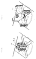
- a next step the spacer 12 is taken away and the inner mould 18 is released from the cast tower segment 23.
- the tower segment 23 is positioned upside down centrally on the foundation 2 ( Figure 6 ).
- Trapezoidal tapered side panels 20, 21 are positioned between the corner segments 6, 19 of the inner and outer moulds 5, 18 to enhance the diameter of the inner and outer moulds 5, 18, so they can be used for casting a next lower tower segment.
- the taper of these panels is such that the lower diameter of the inner mould corresponds to the largest inner diameter of the earlier cast tower segment 23.
- the inner and outer moulds 5, 18 accurately join the inner and outer diameter of the upwardly directed lower edge 24 of the last cast tower segment 23 which forms the bottom of the formwork for the new tower segment to be cast. Since the taper angle is quite small the trapezoidal side panels used for casting higher tower segments are actually narrow strips rather than panels.
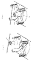
- Figures 7 and 8 show the casting of a final tower segment 31, which is used as the lowest tower segment for the tower to be built.
- the formwork for this segment 31 is formed by the upper edge of the next higher tower segment 33 - here positioned upside down centrally on the foundation 2 - the inner mould 18 expanded by wide tapered panels 21 and the outer mould 5, also expanded by wide tapered panels 20 to obtain a tower segment of a wide diameter, which is more square than circular in cross section.
- the lower segment 31 After the final tower segment 31 has been cast, the lower segment 31 is turned into its regular upright position with the broader side being the lower side. The lower segment is then transported to the site where the tower is to be built. The lower segment 31 is then accurately levelled and aligned, such that its axis is vertical.
- next tower segment 33 is stacked on top of it with the same relative position as during casting. Consequently, after stacking each point of the upper edge of the lower segment faces the same point of the lower edge of the higher segment as during casting of the lower segment. Since the upper edge of the lower tower segment was cast on top of the lower edge of the next higher tower segment, the two edges are complementary shaped so the second segment will accurately join the lower segment and will automatically also be aligned.
- the third tower segment is stacked on top of the second segment, again with the same relative position as during casting of the second tower segment. These steps are repeated until all segments of the tower have been stacked. After all tower segments have been stacked pre-tension cables can be used stretched between top segment and the foundation 2 to draw the tower segments firmly against each other.
Landscapes
- Engineering & Computer Science (AREA)
- Chemical & Material Sciences (AREA)
- Architecture (AREA)
- Life Sciences & Earth Sciences (AREA)
- Mechanical Engineering (AREA)
- Combustion & Propulsion (AREA)
- Sustainable Development (AREA)
- General Engineering & Computer Science (AREA)
- Manufacturing & Machinery (AREA)
- Ceramic Engineering (AREA)
- Materials Engineering (AREA)
- Wood Science & Technology (AREA)
- Sustainable Energy (AREA)
- Civil Engineering (AREA)
- Structural Engineering (AREA)
- Conveying And Assembling Of Building Elements In Situ (AREA)
Priority Applications (1)
| Application Number | Priority Date | Filing Date | Title |
|---|---|---|---|
| EP15153810.5A EP3095569A1 (fr) | 2015-02-04 | 2015-02-04 | Procédé de construction d'une tour constituée de segments en béton |
Applications Claiming Priority (1)
| Application Number | Priority Date | Filing Date | Title |
|---|---|---|---|
| EP15153810.5A EP3095569A1 (fr) | 2015-02-04 | 2015-02-04 | Procédé de construction d'une tour constituée de segments en béton |
Publications (1)
| Publication Number | Publication Date |
|---|---|
| EP3095569A1 true EP3095569A1 (fr) | 2016-11-23 |
Family
ID=52446272
Family Applications (1)
| Application Number | Title | Priority Date | Filing Date |
|---|---|---|---|
| EP15153810.5A Withdrawn EP3095569A1 (fr) | 2015-02-04 | 2015-02-04 | Procédé de construction d'une tour constituée de segments en béton |
Country Status (1)
| Country | Link |
|---|---|
| EP (1) | EP3095569A1 (fr) |
Cited By (1)
| Publication number | Priority date | Publication date | Assignee | Title |
|---|---|---|---|---|
| US12529239B2 (en) | 2022-10-31 | 2026-01-20 | Ge Infrastructure Technology Llc | Wind turbine tower structure with stacked tower sections |
Citations (4)
| Publication number | Priority date | Publication date | Assignee | Title |
|---|---|---|---|---|
| NL7003881A (fr) * | 1970-03-18 | 1971-09-21 | ||
| NL7612731A (en) * | 1976-11-16 | 1978-05-18 | Ballast Nedam Groep N V En Lie | Concrete structure erection system - uses truck with steering wheels lifting parts between horizontal beams while travelling over site |
| US20110107708A1 (en) | 2008-04-01 | 2011-05-12 | Norbert Holscher | Method for producing concrete prefinished parts |
| US20140283478A1 (en) | 2011-11-24 | 2014-09-25 | Wobben Properties Gmbh | Apparatus and method for processing a concrete tower segment of a wind turbine |
-
2015
- 2015-02-04 EP EP15153810.5A patent/EP3095569A1/fr not_active Withdrawn
Patent Citations (4)
| Publication number | Priority date | Publication date | Assignee | Title |
|---|---|---|---|---|
| NL7003881A (fr) * | 1970-03-18 | 1971-09-21 | ||
| NL7612731A (en) * | 1976-11-16 | 1978-05-18 | Ballast Nedam Groep N V En Lie | Concrete structure erection system - uses truck with steering wheels lifting parts between horizontal beams while travelling over site |
| US20110107708A1 (en) | 2008-04-01 | 2011-05-12 | Norbert Holscher | Method for producing concrete prefinished parts |
| US20140283478A1 (en) | 2011-11-24 | 2014-09-25 | Wobben Properties Gmbh | Apparatus and method for processing a concrete tower segment of a wind turbine |
Non-Patent Citations (1)
| Title |
|---|
| "Technisch hoogstandje verkort bouwtijd en verlaagt kosten", HIGHLIGHTS OF HENDRIKS GROEP, April 1994 (1994-04-01) |
Cited By (1)
| Publication number | Priority date | Publication date | Assignee | Title |
|---|---|---|---|---|
| US12529239B2 (en) | 2022-10-31 | 2026-01-20 | Ge Infrastructure Technology Llc | Wind turbine tower structure with stacked tower sections |
Similar Documents
| Publication | Publication Date | Title |
|---|---|---|
| EP2215320B1 (fr) | Procédé de montage d'une tour segmentée en béton précontraint pour générateur éolien et tour | |
| JP5629316B2 (ja) | 伸縮式タワーアセンブリおよび方法 | |
| CN100529275C (zh) | 建造塔架的方法和风力设备 | |
| CN106460355B (zh) | 风轮机用的基座 | |
| US20180305938A1 (en) | Concrete tower and climbing or self-climbing formwork device for its building onsite | |
| CN114054651B (zh) | 一种平面预制桥墩钢筋笼的模块化装置及矩形钢筋笼制作方法 | |
| US4076778A (en) | Climbing formwork | |
| US9487966B2 (en) | System and method for the construction of concrete towers and resulting concrete tower | |
| EP2239398B1 (fr) | Tour | |
| KR20130005832A (ko) | 프리캐스트 거더용 거푸집장치 | |
| US7992359B2 (en) | Alignment brace for insulated concrete walls and method of construction | |
| US8806821B1 (en) | Tower foundation pillar slab and method of producing such | |
| CN107107377B (zh) | 制造用于风力发电机塔架的混凝土结构砌块的方法 | |
| CN113719032A (zh) | 一种多肢柱的柱脚节点施工方法 | |
| JP5896441B1 (ja) | 組立ブロック | |
| JP7126248B2 (ja) | カルバートの製造方法 | |
| EP3403798B1 (fr) | Structure mobile et procédé pour la préfabrication de barres de béton avec précontrainte désirée | |
| CN103790376B (zh) | 用于双曲面建筑物施工的墙体模架及墙体的施工方法 | |
| US9290959B1 (en) | Site-cast coupled prestressed concrete wind tower | |
| CN106795701A (zh) | 预制节段构造物的模板结构体及其施工方法 | |
| TWI523994B (zh) | 地下結構牆面複合式單面模板桁架系統及工法 | |
| CN209491947U (zh) | 一种可伸缩的预应力梁板张拉台座 | |
| CN206616569U (zh) | 预应力预制格构柱 | |
| CN112663943A (zh) | 一种建筑结构墙构筑方法 | |
| JP7288390B2 (ja) | 基礎の施工方法及び基礎 |
Legal Events
| Date | Code | Title | Description |
|---|---|---|---|
| PUAI | Public reference made under article 153(3) epc to a published international application that has entered the european phase |
Free format text: ORIGINAL CODE: 0009012 |
|
| AK | Designated contracting states |
Kind code of ref document: A1 Designated state(s): AL AT BE BG CH CY CZ DE DK EE ES FI FR GB GR HR HU IE IS IT LI LT LU LV MC MK MT NL NO PL PT RO RS SE SI SK SM TR |
|
| AX | Request for extension of the european patent |
Extension state: BA ME |
|
| 17P | Request for examination filed |
Effective date: 20170516 |
|
| RBV | Designated contracting states (corrected) |
Designated state(s): AL AT BE BG CH CY CZ DE DK EE ES FI FR GB GR HR HU IE IS IT LI LT LU LV MC MK MT NL NO PL PT RO RS SE SI SK SM TR |
|
| 17Q | First examination report despatched |
Effective date: 20190325 |
|
| GRAP | Despatch of communication of intention to grant a patent |
Free format text: ORIGINAL CODE: EPIDOSNIGR1 |
|
| INTG | Intention to grant announced |
Effective date: 20190919 |
|
| STAA | Information on the status of an ep patent application or granted ep patent |
Free format text: STATUS: THE APPLICATION IS DEEMED TO BE WITHDRAWN |
|
| 18D | Application deemed to be withdrawn |
Effective date: 20200130 |