EP3095597A2 - Vorrichtung zum falten von kartonzuschnitten - Google Patents
Vorrichtung zum falten von kartonzuschnitten Download PDFInfo
- Publication number
- EP3095597A2 EP3095597A2 EP16170826.8A EP16170826A EP3095597A2 EP 3095597 A2 EP3095597 A2 EP 3095597A2 EP 16170826 A EP16170826 A EP 16170826A EP 3095597 A2 EP3095597 A2 EP 3095597A2
- Authority
- EP
- European Patent Office
- Prior art keywords
- folding
- drive shaft
- carton blank
- hook
- folding hook
- Prior art date
- Legal status (The legal status is an assumption and is not a legal conclusion. Google has not performed a legal analysis and makes no representation as to the accuracy of the status listed.)
- Granted
Links
Images






Classifications
-
- B—PERFORMING OPERATIONS; TRANSPORTING
- B31—MAKING ARTICLES OF PAPER, CARDBOARD OR MATERIAL WORKED IN A MANNER ANALOGOUS TO PAPER; WORKING PAPER, CARDBOARD OR MATERIAL WORKED IN A MANNER ANALOGOUS TO PAPER
- B31B—MAKING CONTAINERS OF PAPER, CARDBOARD OR MATERIAL WORKED IN A MANNER ANALOGOUS TO PAPER
- B31B50/00—Making rigid or semi-rigid containers, e.g. boxes or cartons
-
- B—PERFORMING OPERATIONS; TRANSPORTING
- B31—MAKING ARTICLES OF PAPER, CARDBOARD OR MATERIAL WORKED IN A MANNER ANALOGOUS TO PAPER; WORKING PAPER, CARDBOARD OR MATERIAL WORKED IN A MANNER ANALOGOUS TO PAPER
- B31B—MAKING CONTAINERS OF PAPER, CARDBOARD OR MATERIAL WORKED IN A MANNER ANALOGOUS TO PAPER
- B31B50/00—Making rigid or semi-rigid containers, e.g. boxes or cartons
- B31B50/26—Folding sheets, blanks or webs
- B31B50/52—Folding sheets, blanks or webs by reciprocating or oscillating members, e.g. fingers
- B31B50/54—Folding sheets, blanks or webs by reciprocating or oscillating members, e.g. fingers operating on moving material
-
- B—PERFORMING OPERATIONS; TRANSPORTING
- B31—MAKING ARTICLES OF PAPER, CARDBOARD OR MATERIAL WORKED IN A MANNER ANALOGOUS TO PAPER; WORKING PAPER, CARDBOARD OR MATERIAL WORKED IN A MANNER ANALOGOUS TO PAPER
- B31B—MAKING CONTAINERS OF PAPER, CARDBOARD OR MATERIAL WORKED IN A MANNER ANALOGOUS TO PAPER
- B31B50/00—Making rigid or semi-rigid containers, e.g. boxes or cartons
- B31B50/26—Folding sheets, blanks or webs
- B31B50/262—Folding sheets, blanks or webs involving folding, leading, or trailing flaps of blanks
Definitions
- the present invention relates to a folding hook and a device for folding cardboard blanks, which is for example in a folding box gluer.
- Folding cartons are cut-to-size prefabricated boxes, which are delivered in a collapsed state by the manufacturer to processing companies to save space. There, the carton blanks are unfolded into the carton with simple hand movements or by machine.
- the carton blanks are usually made of cardboard, preferably made of corrugated cardboard.
- Some carton blanks include tabs that are folded by about 180 ° at the manufacturer. Most of these folded tabs are then glued to an adjacent part of the carton blank. These processes take place in folding box gluing machines. For this purpose, the area-trained carton blanks are conveyed in the transport direction by the gluing machine and processed during the process.
- Vorderfalthaken For folding over the tabs on a front in the transport direction edge of the carton blank rotating devices are known, which are referred to as Vorderfalthaken.
- Front catch and Schufalthaken are arranged in conventional machines each on a separate shaft, each having a separate drive (servo motor), which is controlled separately by a higher-level machine control.
- Object of the present invention is to simplify the folding of front and rear flaps and to provide a particularly compact and inexpensive device.
- the folding hook In the region of the convexly curved projection, the folding hook has a thickness D 16 which is greater than in the crescent-shaped region (D 16 > D 20 ). Therefore, the convexly curved projection of the folding hook according to the invention projects beyond the contour of a conventional rear folding hook on a side opposite the crescent-shaped and concave area.
- folding hook according to the invention can serve alternately as Vorderfalthaken and as Hinterfalthaken.
- the folding hook according to the invention first raises the tab on the front edge and then unfolds the flap located on the trailing edge.
- the folding hook according to the invention takes over successively two functions and is therefore also referred to in the context of the invention as a combination folding hook.
- the folding hook according to the invention is arranged on a rotating drive shaft.
- a plurality of such combination folding hooks can be arranged at different positions in the processing line of the folding box gluing machine in order to successively be able to fold different flaps which are arranged next to one another at the front and rear edges.
- At least two, preferably three folding hooks are arranged at a same angular distance as a folding hook arrangement on a drive shaft.
- the arrangement of three folding hooks thus resembles a Triskele.
- the drive shaft is controlled as a function of the transport speed and / or the position of the carton blank, thereby ensuring that the convexly curved projection and the substantially crescent-shaped shape of the folding hooks at the right time at a front and a rear flap of the Attack carton blank.
- the drive shaft rotates stepwise and / or with different rotational speed. Assuming that the transport speed of the carton blank is done at a uniform speed, it may be necessary for effectively folding the tab that the drive shaft in certain periods of time, the folding hooks or only slowly move, or at certain times the folding hooks for a short time especially to move fast.
- the drive shaft does not run at a constant speed.
- the device according to the invention can have scanning devices for the carton blank and / or suitable sensors which determine the respective current position of the tab to be folded over.
- the signals of the scanning devices or sensors are evaluated in a control device and depending on the determined result, the drive shaft is rotated by the drive in rotation.
- FIG. 1 shows a Vorderfalthaken 10 of the prior art.
- FIG. 1 are two Vorderfalthaken 10 offset by 180 ° to a common drive shaft 12 arranged with hexagonal cross-section.
- the two Vorderfalthaken 10 are connected to each other by a chain link 14 and fixed by means of a clamping screw 15 to the drive shaft 12.
- each have a convexly curved projection 16 is formed in FIG. 1 is formed annular.
- the convexly curved projection 16 is usually pressed from below against a arranged at the front edge of a carton blank tab.
- the tab is raised and moves against a fixed "obstacle", which causes the actual folding of this tab.
- the transport movement of the carton blank supports or allows the folding of this tab only.
- FIG. 2 shows two oppositely arranged Stromfalthaken 18 according to the prior art.
- the Hinterfalthaken 18 is bent on its inside at least partially sickle-shaped.
- the Hinterfalthaken 18 folds with its rounded tip 21 a at a trailing edge of a carton blank (not shown) tab.
- the crescent-shaped region 20 is designed or curved so that the Schufalthaken 18 touches the tab only with its tip 21. This prevents the Schufalthaken 18 damaged the tab when folding.
- the tip 21 is thus the actual effective range of the Schufalthakens 18, which at least partially rotated under a from the rear of the carton blank (seen in the transport direction) cut tab of a carton blank and then folds the tab by a further rotational movement of the Deutschenfalthakens 18 about the drive shaft 12 ,
- the rotational movement of the drive axle 12 must be controlled so that the tip 21 of the Schufalthakens 18 at least briefly "overhauled" the rear end of the carton blank in the transport direction.
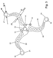
- FIG. 3 shows three folding hooks 22 according to the invention, which are arranged offset by 120 ° to each other on a drive shaft 12. This arrangement is reminiscent of a so-called Triskele and is a preferred arrangement 23.
- the combination folding hooks 22 according to the invention have features of a front folding hook 10 and a back folding hook 18 of the prior art.
- a convexly curved projection 16 is formed at the free ends of the folding hook 22, wherein the folding hook on the convexly curved projection 16 has a thickness D 16 which is greater than a thickness D 20 in the crescent-shaped area 20.
- the convexly curved projection 16, as well as in FIG. 1 be formed annular. The projection 16 serves to realize the Vorderfalthakenfunktion.
- the folding hook 22 at its free end and on a concavely curved side of the crescent-shaped region 20, has a projection.
- the folding hooks 22 in their course, in particular on the inside of the folding hook 22, a crescent-shaped portion 20 on.
- the area 20 serves to realize the Deutschenfalthakenfunktion.
- the tip 21 is formed only on the inside of the folding hook 22, that is, in continuation of the crescent-shaped portion 20. On the outside, where the convex curved projection 16 is present, no pronounced tip is present and also not required.
- the folding hook 22 according to the invention thus represents aticiansfalthaken, which combines the functions of a Vorderfalthakens and a Schufalthakens.
- FIG. 4 shows a part of a processing line in a plan view.
- a folding or folding module 24 (hereinafter referred to as "module") are recessed in the conveyor belt 26 in grooves.
- the transport belts 26 serve to convey a carton blank 28 through the module 24.
- the transport direction (feed direction) is indicated by an arrow with the reference numeral 30.
- the transport belts 26 are arranged offset to one another in part.
- the transport belts 26 in the module 24 are laterally displaceable (see reference numeral 32) in order to adjust the module to the processing of different large carton blanks.
- the module 24 is adapted to automatically fold on two sides of a carton blank 28 tabs 34, 34 'at the front edge and the trailing edge of the carton blank.
- a fold line for the carton blank 28 is identified by the reference numeral 36.
- the folding hooks 22 are arranged in the module 24, as seen in the transport direction 30, at two different positions 38, 38 'folding hooks 22 are arranged, wherein the folding hooks 22 at the position 38 of the folding over outer tabs 34, 34 'of the carton blank 28 is used. In the position 38 ', the folding hooks 22 are arranged for folding over tabs arranged in the interior of the carton blank.
- FIG. 5a shows circulating the transport belt 26.
- a flat trained cardboard blank 28 is placed, which is moved by the transport belt 26 in the transport direction 30.
- the carton blank 28 has notches 42. Through these cuts 42, the folding tabs 34, 34 'are “divided”. In addition, the carton blank 28 has bent edges 44. Along these kink edges 44, the tabs 34, 34 'folded.
- the folding hook arrangement 23 is arranged on a rotating drive shaft 12.
- a direction of rotation of the drive shaft 12 is designated by the reference numeral 40.
- one of the folding hooks 22 touches the tab 34 located at the front edge of the carton blank from below.
- FIG. 5b the carton blank 28 has moved on and the drive shaft 12 has turned so far in the direction of rotation 40 that the convexly curved projection 16 at the free end of the folding hook 22 raises the front tab 34.
- the tab 34 bends so far at the bend edge 44 that the tab 34 strikes a fixed fold-over roll 46 disposed above the carton blank 28 when the carton blank 28 is further transported through the module 24.
- the Umklapprolle 46 then takes over the actual folding of the tab 34. Under folding it is a bend of the tabs 34, 34 'by significantly more than 90 °, preferably by about 180 °, understood. This process is in the FIG. 5c illustrated.
- the Umklapprolle can also be used a brush or a hold-down rod.
- FIG. 5d shows the completely folded flap 34.
- the carton blank 28 has now been moved so far in the transport direction 30 that the folding hooks 22, the tab 34 can not reach.
- the drive shaft 12 is temporarily stopped or rotates only very slowly. The transport of the carton blank 28 continues in the transport direction 30.
- the drive shaft 12 In order to further fold over the tab 34 ', the drive shaft 12 must briefly perform a relatively fast rotational movement, so that the tip 21 of the folding hook 22' overtakes 'the moving carton blank 28 and as a result the tab 34' is folded forwards. This situation is in the FIG. 5f shown.
- FIG. 5g the rotational movement of the folding hook assembly 23 is almost complete. Due to the sickle-shaped formation 20 of the folding hook 22 prevents the folding hook 22 the Umklappterrorism the rear tab 34 'bothers, or that the folding hook 22, the tab 34' is not damaged.
- FIG. 5h the folding of the front flap 34 and the folding of the rear flap 34 'is completed.
- the rotational movement of the folding hook arrangement 23 can be interrupted until a further carton blank 28 is brought onto the transport belt 26 in the region of the folding hook arrangement 23.
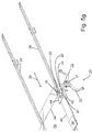
- FIG. 6 an inventive arrangement of a Vorderfalthaken 10 and a Schufalthaken 20 on a common drive shaft 12 is shown.
- the known from the prior art folding hooks 10, 20 are successively used.
- the cost advantage and the saving of footprint are achieved.
- the control of the drive shaft 12 is in this embodiment compared to the first embodiment according to the FIGS. 5a to h something else.
- the performance [carton blanks / min] of both embodiments is similar.
- FIG. 6 a combination according to the invention of a front-folding hook and a rear-folding hook is shown, which are arranged on a common shaft.
- Both folding hooks are arranged on a common shaft.
- Essential advantages of the invention namely saving space, reducing the number of waves and drives with the same functionality, also achieved.
- folding hooks can be used, which are in and of themselves known from the prior art.
- the front latch and the rear latch are designed as separate components.
- the control of the common drive shaft can build on existing controls of front latch and the Schufalthaken (on separate drive shafts). This considerably simplifies and simplifies the integration into the machine control.
Landscapes
- Making Paper Articles (AREA)
- Cartons (AREA)
Description
- Die vorliegende Erfindung betrifft einen Falthaken und eine Vorrichtung zum Falten von Kartonzuschnitten, die zum Beispiel in einer Faltschachtelklebemaschine ist.
- Faltschachteln sind aus Zuschnitten industriell vorgefertigte Schachteln, die platzsparend in zusammengelegtem Zustand vom Hersteller an verarbeitende Unternehmen geliefert werden. Dort werden die Kartonzuschnitte mit einfachen Handgriffen oder maschinell zur Schachtel aufgefaltet. Die Kartonzuschnitte sind in der Regel aus Pappe, vorzugsweise aus Wellpappe hergestellt.
- Manche Kartonzuschnitte umfassen Laschen, die beim Hersteller um etwa 180° umgeklappt werden. Meist werden diese umgeklappten Laschen anschließend mit einem benachbarten Teil der Kartonzuschnitts verklebt. Diese Vorgänge finden in Faltschachtelklebemaschinen statt. Zu diesem Zweck werden die flächig ausgebildeten Kartonzuschnitte in Transportrichtung durch die Klebemaschine gefördert und währenddessen bearbeitet.
- Zum Umklappen der Laschen an einer in Transportrichtung vorderen Kante des Kartonzuschnitts sind rotierende Vorrichtungen bekannt, die als Vorderfalthaken bezeichnet werden.
- Zum Umklappen der Laschen an einer in Transportrichtung hinteren Kante des Kartonzuschnitts sind rotierende Vorrichtungen bekannt, die als Hinterfalthaken bezeichnet werden.
- Vorderfalthaken und Hinterfalthaken sind bei herkömmlichen Maschinen jeweils auf einer separaten Welle angeordnet, die jeweils einen separaten Antrieb (Servomotor) aufweisen, der gesondert von einer übergeordneten Maschinensteuerung angesteuert wird.
- Aus der
US 4,544,368 ist eine Faltschachtelklebemaschine bekannt, wobei die in Transportrichtung vorne liegenden Laschen umgeklappt werden. Dazu weist die Faltschachtelklebemaschine eine Einrichtung zum Klappen der vorderen Laschen nach oben auf, die hakenförmige, schwenkbare Elemente umfasst. Das Umklappen der in Transportrichtung an der in Transportrichtung hinteren Kante des Kartonzuschnitts ist in dieser Druckschrift nicht beschrieben. - Aus der
US 2011/0092350 A1 ist eine Vorrichtung zum Falten von Faltschachtelzuschnitten bekannt, die Vorderfalthaken und sichelförmige Hinterfalthaken aufweist. An allen sichelförmigen Hinterfalthaken ist in unmittelbarer Nähe zu einer Antriebswelle jeweils Vorderfalthaken angeordnet. - Aus der
DE 1 956 268 A ist eine Vorrichtung zum Falten von Faltschachtelzuschnitten mit einer Faltscheibe bekannt. An dieser Faltscheibe sind voneinander beabstandet eine Aufrichtklappe und eine Faltklappe angeordnet, welche die Funktionen eines Vorderfalthakens und eines Hinterfalthakens übernehmen. - Aufgabe der vorliegenden Erfindung ist es, das Umklappen von vorderen und hinteren Laschen zu vereinfachen und eine besonders kompakte und kostengünstige Vorrichtung bereitzustellen.
- Diese Aufgabe wird dadurch gelöst, dass
- der erfindungsgemäße Falthaken an seinem freien Ende einen konvex gekrümmten Vorsprung umfasst und damit als Vorderfalthaken das Umklappen einer in Transportrichtung vorderen Lasche des Kartonzuschnitts wirkt, und
- der Falthaken auf einer dem konvex gekrümmten Bereich gegenüberliegenden Seite eine im Wesentlichen sichelförmige und konkave Form aufweist, die zum Umklappen einer in Transportrichtung hinteren Lasche des Kartonzuschnitts dient.
- Im Bereich des konvex gekrümmten Vorsprungs hat der Falthaken eine Dicke D16, die größer ist als in dem sichelförmigen Bereich (D16 > D20). Daher ragt der konvex gekrümmte Vorsprung des erfindungsgemäßen Falthakens auf einer dem sichelförmigen und konkaven Bereich gegenüberliegenden Seite über die Kontur eines herkömmlichen Hinterfalthakens hinaus.
- Das bedeutet, dass der erfindungsgemäße Falthaken abwechselnd als Vorderfalthaken und als Hinterfalthaken dienen kann. Der erfindungsgemäße Falthaken hebt zunächst die Lasche an der Vorderkante an und klappt anschließend die an der Hinterkante befindliche Lasche um.
- Der erfindungsgemäße Falthaken übernimmt nacheinander zwei Funktionen und wird daher auch im Zusammenhang mit der Erfindung als Kombinationsfalthaken bezeichnet.
- Dadurch werden nur eine Welle und ein Antrieb für den erfindungsgemäßen Kombinationsfalthaken benötigt, um Laschen an der Vorderkante und an der Hinterkante eine Kartonzuschnitts bei einem Durchlauf durch die erfindungsgemäße Vorrichtung umzuklappen. Das reduziert die Herstellungskosten und den Platzbedarf der erfindungsgemäßen Vorrichtung signifikant.
- Vorzugsweise ist der erfindungsgemäße Falthaken an einer rotierenden Antriebswelle angeordnet. Es können mehrere solcher Kombinationsfalthaken an unterschiedlichen Positionen in der Bearbeitungsstraße der Faltschachtelklebemaschine angeordnet sein, um verschiedene Klappen, die an der Vorder- und Hinterkante nebeneinander angeordnet sind, nacheinander umklappen zu können.
- In einer bevorzugten Ausführungsform ist vorgesehen, dass mindestens zwei, vorzugsweise drei Falthaken in einem gleichen Winkelabstand als Falthakenanordnung auf einer Antriebswelle angeordnet sind. Die Anordnung von drei Falthaken ähnelt somit einer Triskele. Wenn mehrere erfindungsgemäße Kombinationsfalthaken um eine Antriebswelle herum angeordnet werden, nimmt die Leistungsfähigkeit der erfindungsgemäßen Vorrichtung zu, bei nahezu gleichen Kosten.
- Zum schnelleren Bearbeiten von Kartonschnitten in der Faltschachtelklebemaschine können in der Faltschachtelklebemaschine mehrere Triskelen in Transportrichtung unterschiedlichen Positionen angeordnet sein.
- Ferner ist vorgesehen, dass die Antriebswelle in Abhängigkeit der Transportgeschwindigkeit und/oder der Position des Kartonzuschnitts angesteuert wird, Dadurch wird sichergestellt, dass der konvex gekrümmte Vorsprung und die im Wesentlichen sichelförmige Form der Falthaken jeweils zum richtigen Zeitpunkt an einer vorderen und einer hinteren Lasche des Kartonzuschnitts angreifen.
- Ergänzend dazu ist vorgesehen, dass die Antriebswelle sich schrittweise und/oder mit unterschiedlicher Drehgeschwindigkeit dreht. Wenn man davon ausgeht, dass die Transportgeschwindigkeit des Kartonzuschnitts mit gleichmäßiger Geschwindigkeit geschieht, kann es zum effektiven Umklappen der Lasche nötig sein, dass die Antriebswelle in bestimmten Zeitabschnitten die Falthaken nicht oder nur langsam weiterbewegen, bzw. zu bestimmten Zeitpunkten die Falthaken für kurze Zeit besonders schnell zu bewegen.
- Die Antriebswelle läuft dabei nicht in einer konstanten Geschwindigkeit.
- Um die Drehbewegung der Antriebswelle steuern zu können, kann die erfindungsgemäße Vorrichtung Abtasteinrichtungen für den Kartonzuschnitt und/oder geeignete Sensoren aufweisen, die die jeweilige aktuelle Position der umzuklappenden Lasche ermitteln. Die Signale der Abtasteinrichtungen bzw. Sensoren werden in einer Steuereinrichtung ausgewertet und je nach dem ermittelten Ergebnis wird die Antriebswelle von deren Antrieb in Drehung versetzt.
- Weitere Vorteile ergeben sich aus der nachfolgenden Beschreibung und den beigefügten Figuren.
- Ausführungsbeispiele der Erfindung sind in den Figuren dargestellt und werden in der nachfolgenden Beschreibung näher erläutert. Es zeigen, jeweils in schematischer Form:
- Figur 1
- zwei um 180° versetzt zueinander auf einer Antriebswelle angeordnete Vorderfalthaken (Stand der Technik);
- Figur 2
- zwei um 180° versetzt zueinander auf einer Antriebswelle angeordnete Hinterfalthaken (Stand der Technik);
- Figur 3
- einen erfindungsgemäßen (Kombinations-)Falthaken in einer bevorzugten Ausführungsform;
- Figur 4
- eine Bearbeitungsstraße einer Faltschachtelklebemaschine in einer Draufsicht;
- Figur 5
- acht Arbeitsschritte (
Fig. 5a - 5h ) des Falthakens ausFig. 3 beim Umklappen von Laschen eines Kartonzuschnitts und - Figur 6
- eine erfindungsgemäße Kombination eines Vorderfalthakens und eines Hinterfalthakens.
-
Figur 1 zeigt einen Vorderfalthaken 10 aus dem Stand der Technik. InFigur 1 sind zwei Vorderfalthaken 10 um 180° versetzt an einer gemeinsamen Antriebswelle 12 mit sechseckigem Querschnitt angeordnet. Die beiden Vorderfalthaken 10 sind durch ein Kettenglied 14 miteinander verbunden und mittels einer Spannschraube 15 an der Antriebswelle 12 fixiert. - An dem freien Ende des Vorderfalthakens 10 ist jeweils ein konvex gekrümmter Vorsprung 16 ausgebildet, der in
Figur 1 ringförmig ausgeformt ist. Durch eine Drehung der Antriebswelle wird der konvex gekrümmte Vorsprung 16 in der Regel von unten gegen eine an der Vorderkante eines Kartonzuschnitts angeordnet Lasche gedrückt. In Folge dessen wird die Lasche angehoben und bewegt sich gegen ein feststehendes "Hindernis", welches das eigentliche Umklappen dieser Lasche bewirkt. Die Transportbewegung des Kartonzuschnitts unterstützt beziehungsweise ermöglicht das Umklappen dieser Lasche erst. - Wenn auch am hinteren Teil des Kartonzuschnitts (in Transportrichtung gesehen) eine Lasche vorhanden ist, die ebenfalls umgeklappt werden soll, wird gemäß dem Stand der Technik ein gesonderter Hinterfalthaken 18 benötigt.
-
Figur 2 zeigt zwei einander gegenüberliegend angeordnete Hinterfalthaken 18 nach dem Stand der Technik. - Der Hinterfalthaken 18 ist an seiner Innenseite zumindest bereichsweise sichelförmig gebogen. Der Hinterfalthaken 18 klappt mit seiner abgerundeten Spitze 21 eine an einer Hinterkante eines Kartonzuschnitts (nicht dargestellt) Lasche um. Der sichelförmige Bereich 20 ist so gestaltet, bzw. gekrümmt, dass der Hinterfalthaken 18 nur mit seiner Spitze 21 die Lasche berührt. Dadurch wird verhindert, dass der Hinterfalthaken 18 die Lasche beim Umklappen beschädigt.
- Die Spitze 21 ist somit der eigentliche Wirkbereich des Hinterfalthakens 18, welche die zumindest teilweise unter eine aus dem hinteren Teil des Kartonzuschnitts (in Transportrichtung gesehen) ausgeschnittene Lasche eines Kartonzuschnitts gedreht und anschließend durch eine weitere Drehbewegung des Hinterfalthakens 18 um die Antriebsachse 12 die Lasche umklappt.
- Dabei muss die Drehbewegung der Antriebsachse 12 so gesteuert werden, dass die Spitze 21 des Hinterfalthakens 18 zumindest kurzzeitig das hintere Ende des Kartonzuschnitts in Transportrichtung "überholt".
-
Figur 3 zeigt drei erfindungsgemäße Falthaken 22, die um 120° versetzt zueinander an einer Antriebswelle 12 angeordnet sind. Diese Anordnung erinnert an eine sogenannte Triskele und ist eine bevorzugte Anordnung 23. - Die erfindungsgemäßen Kombinations-Falthaken 22 weisen Merkmale eines Vorderfalthakens 10 und eines Hinterfalthakens 18 aus dem Stand der Technik auf. So ist an den freien Enden des Falthakens 22 jeweils ein konvex gekrümmter Vorsprung 16 ausgebildet, wobei der Falthaken an dem konvex gekrümmten Vorsprung 16 eine Dicke D16 hat, die größer ist als eine Dicke D20 in dem sichelförmigen Bereich 20. Um Gewicht zu sparen, kann der konvex gekrümmten Vorsprung 16, ebenso wie in
Figur 1 , ringförmig ausgeformt sein. Der Vorsprung 16 dient zur Realisierung der Vorderfalthakenfunktion. - Anders ausgedrückt: An seinem freien Ende und auf der einer konkav gekrümmten Seite des sichelförmigen Bereichs 20 weist der erfindungsgemäße Falthaken 22 einen Vorsprung auf.
- Außerdem weisen die Falthaken 22 in ihrem Verlauf, insbesondere an der Innenseite des Falthakens 22, einen sichelförmig gebogenen Bereich 20 auf. Der Bereich 20 dient zur Realisierung der Hinterfalthakenfunktion.
- Die Spitze 21 ist nur auf der Innenseite des Falthakens 22, d. h. in Fortführung des sichelförmigen Bereichs 20 ausgebildet. An der Außenseite, dort wo der konvex gekrümmte Vorsprung 16 vorhanden ist, ist keine ausgeprägte Spitze vorhanden und im Übrigen auch nicht erforderlich. Der erfindungsgemäße Falthaken 22 stellt somit einen Kombinationsfalthaken dar, der die Funktionen eines Vorderfalthakens und eines Hinterfalthakens vereint.
-
Figur 4 zeigt einen Teil einer Bearbeitungsstraße in einer Draufsicht. Dargestellt ist ein Falt- oder Umklappmodul 24 (nachfolgend als "Modul" bezeichnet) bei dem Transportriemen 26 in Nuten eingelassen sind. Die Transportriemen 26 dienen dazu, einen Kartonzuschnitt 28 durch das Modul 24 zu befördern. Die Transportrichtung (Vorschubrichtung) ist durch einen Pfeil mit dem Bezugszeichen 30 gekennzeichnet. Um den Kartonzuschnitt 28 auch bei umgeklappten Seitenwänden befördern zu können, sind die Transportriemen 26 zum Teil versetzt zueinander angeordnet. Vorzugsweise sind die Transportriemen 26 im Modul 24 seitlich verschiebbar (vgl. Bezugszeichen 32), um das Modul auf die Verarbeitung unterschiedliche großer Kartonzuschnitte einstellen zu können. Das Modul 24 ist dazu eingerichtet, auf zwei Seiten eines Kartonzuschnitts 28 Laschen 34, 34' an der Vorderkante und der Hinterkante des Kartonzuschnitts automatisch umzuklappen. Eine Faltlinie für den Kartonzuschnitt 28 ist mit dem Bezugszeichen 36 gekennzeichnet. - In dem Modul 24 sind, in Transportrichtung 30 gesehen, an zwei unterschiedlichen Positionen 38, 38' Falthaken 22 angeordnet, wobei die Falthaken 22 an der Position 38 dem Umklappen der äußeren Laschen 34, 34' des Kartonzuschnitts 28 dient. In der Position 38' sind die Falthaken 22 zum Umklappen von im Innern des Kartonzuschnitts angeordneten Laschen angeordnet.
- In den Positionen 38, 38' ist in
Figur 4 im Wesentlichen die Antriebswelle 12 mit den Falthaken 22 dargestellt. - Die Funktion und die Arbeitsweise der Falthakenanordnung 23 mit drei erfindungsgemäßen Falthaken 22 (gemäß
Figur 3 ), wie sie bspw. an der Position 38 in der Faltschachtelklebemaschine angeordnet sein könnte, wird nachfolgend mit Hilfe derFiguren 5a bis 5h beschrieben. In diesen Figuren werden nur die für das Verständnis notwendigen Bauteil des Moduls 24 und der sich durch das Modul 24 bewegende Kartonzuschnitt 28 (in verschiedenen Positionen) dargestellt. -
Figur 5a zeigt umlaufende die Transportriemen 26. Auf den Transportriemen 26 ist ein flächig ausgebildeter Kartonzuschnitt 28 aufgelegt, der durch die Transportriemen 26 in Transportrichtung 30 bewegt wird. - Der Kartonzuschnitt 28 weist Einschnitte 42 auf. Durch diese Einschnitte 42 werden die umklappbaren Laschen 34, 34' "abgeteilt". Darüber hinaus weist der Kartonzuschnitt 28 Knickkanten 44 auf. Entlang dieser Knickkanten 44 werden die Laschen 34, 34' umgeklappt.
- Die Falthakenanordnung 23 ist auf einer rotierenden Antriebswelle 12 angeordnet. Eine Drehrichtung der Antriebswelle 12 ist mit dem Bezugszeichen 40 gekennzeichnet.
- Durch eine geeignete Ansteuerung der Antriebswelle 12 berührt einer der Falthaken 22 die an der Vorderkante des Kartonzuschnitts befindliche Lasche 34 von unten.
- In
Figur 5b hat sich der Kartonzuschnitt 28 weiterbewegt und die Antriebswelle 12 hat sich so weit in Drehrichtung 40 gedreht, dass der konvex gekrümmte Vorsprung 16 am freien Ende des Falthakens 22 die vordere Lasche 34 anhebt. In Folge dessen knickt die Lasche 34 an der Knickkante 44 so weit nach oben, dass die Lasche 34 auf eine oberhalb des Kartonzuschnitts 28 angeordnete, ortsfeste Umklapprolle 46 trifft, wenn der Kartonzuschnitt 28 weiter durch das Modul 24 transportiert wird. Die Umklapprolle 46 übernimmt dann das eigentliche Umklappen der Lasche 34. Unter Umklappen wird dabei eine Biegung der Laschen 34, 34' um deutlich mehr als 90°, bevorzugt um etwa 180°, verstanden. Dieser Vorgang ist in derFigur 5c illustriert. Alternativ zu der Umklapprolle kann auch eine Bürste oder eine Niederhalterstange eingesetzt werden. - In
Figur 5c wurde die Antriebswelle 12 so weit in Drehrichtung 40 gedreht, dass keiner der Falthaken 22 die Lasche 34 berührt. Die Umklapprolle 46 ist weiterhin mit der Lasche 34 in Kontakt. Durch den (weiteren) Vorschub des Kartonzuschnitts 28 in Transportrichtung 30 drückt die Umklapprolle 46 die Lasche 34 weiter nach hinten und unten. -
Figur 5d zeigt die vollständig umgeklappte Lasche 34. Der Kartonzuschnitt 28 ist nun so weit in Transportrichtung 30 bewegt worden, dass die Falthaken 22 die Lasche 34 nicht mehr erreichen können. Die Antriebswelle 12 steht kurzzeitig still oder dreht sich nur sehr langsam. Der Transport des Kartonzuschnitts 28 läuft weiter in Transportrichtung 30. - In
Figur 5e hat die von der Lasche 34' verdeckte Spitze 21 eines Falthakens 22 die hintere Lasche 34' des Kartonzuschnitts 28 erreicht. Durch die nun wieder einsetzende Drehbewegung der Antriebswelle 12 in Drehrichtung 40 hebt die Spitze 21 des Falthakens 22 die hintere Lasche 34' an, wodurch die Lasche 34' um die Knickkante 44 abknickt. - Um die Lasche 34' weiter umzuklappen, muss die Antriebswelle 12 kurzzeitig eine relativ schnelle Drehbewegung ausführen, so dass die Spitze 21 des Falthakens 22 den sich bewegenden Kartonzuschnitt 28 'überholt' und in Folge dessen die Lasche 34' nach vorne umgeklappt wird. Diese Situation ist in der
Figur 5f dargestellt. - In
Figur 5g ist die Drehbewegung der Falthakenanordnung 23 nahezu abgeschlossen. Durch die sichelförmige Ausbildung 20 des Falthakens 22 wird verhindert, dass der Falthaken 22 die Umklappbewegung der hinteren Lasche 34' stört, bzw. dass der Falthaken 22 die Lasche 34' nicht beschädigt. - In
Figur 5h ist das Umklappen der vorderen Lasche 34 und das Umklappen der hinteren Lasche 34' beendet. Die Drehbewegung der Falthakenanordnung 23 kann unterbrochen werden, bis ein weiterer Kartonzuschnitt 28 auf den Transportriemen 26 in den Bereich der Falthakenanordnung 23 herangeführt wird. - In der
Figur 6 ist eine erfindungsgemäße Anordnung von einem Vorderfalthaken 10 und einem Hinterfalthaken 20 auf einer gemeinsamen Antriebswelle 12 dargestellt. Bei dieser Anordnung kommen die aus dem Stand der Technik bekannten Falthaken 10, 20 nacheinander zum Einsatz. Dies bedeutet, dass ein wesentlicher Vorteil der Erfindung, nämlich die Notwendigkeit nur eine Antriebswelle 12 vorzusehen, auch durch diese Anordnung erreicht wird. In Folge dessen werden auch der Kostenvorteil und die Einsparung an Aufstellfläche erreicht. Die Steuerung der Antriebswelle 12 ist bei diesem Ausführungsbeispiel gegenüber dem ersten Ausführungsbeispiel gemäß derFiguren 5a bis h etwas anders. Die Leistungsfähigkeit [Kartonzuschnitte/min] beider Ausführungsformen ist ähnlich. - In der
Figur 6 ist eine erfindungsgemäße Kombination eines Vorderfalthakens und eines Hinterfalthakens dargestellt, die auf einer gemeinsamen Welle angeordnet sind. Dadurch, dass beide Falthaken auf einer gemeinsamen Welle angeordnet sind, werden wesentliche erfindungsgemäße Vorteile, nämlich Einsparung von Bauraum, Reduktion der Zahl der Wellen und Antriebe bei gleicher Funktionalität, ebenfalls erreicht. Dabei können Falthaken zum Einsatz kommen, die an und für sich aus dem Stand der Technik bekannt sind. Der Vorderfalthaken und der Hinterfalthaken sind als separate Bauteile ausgeführt. Dadurch wird unter anderem die Umrüstung bestehender Vorrichtungen zum Umklappen von Laschen eines Kartonzuschnitts umfassend eine Transporteinrichtung von Kartonzuschnitten erleichtert. Auch die Steuerung der gemeinsamen Antriebswelle kann auf bereits vorhandenen Steuerungen von Vorderfalthaken und der Hinterfalthaken (auf separaten Antriebswellen) aufbauen. Das erleichtert und vereinfacht die Einbindung in die Maschinensteuerung erheblich. - Die Arbeitsweise entspricht weitestgehend der im Zusammenhang mit den
Figuren 5a bis 5h erläuterten Arbeitsweise, so dass diesbezüglich auf diese Figuren und deren Beschreibung verwiesen wird.
Claims (8)
- Falthaken (22) zum Umklappen von Laschen (34, 34') eines flächig ausgebildeten Kartonzuschnitts (28), dadurch gekennzeichnet, dass der Falthaken (22) an einem freien Ende (21) einen konvex gekrümmten Vorsprung (16) umfasst und dass der Falthaken (22) in einem dem konvex gekrümmten Vorsprung (16) gegenüberliegenden Bereich (20) eine im Wesentlichen sichelförmige und konkave Form aufweist
- Falthaken (22) nach Anspruch 1, dadurch gekennzeichnet, dass zwei oder drei Falthaken (22) als Falthakenanordnung (23) auf einer gemeinsamen Antriebswelle (12) angeordnet sind.
- Vorrichtung zum Umklappen von Laschen (34, 34') eines Kartonzuschnitts (28) umfassend eine Transporteinrichtung zum Transport eines Kartonzuschnitts (28) sowie Mittel zum Umklappen einer Lasche (34) an einer Vorderkante eines Kartonzuschnitts (28) sowie Mittel zum Umklappen einer Lasche (34') an einer Hinterkante eines Kartonzuschnitts (28), dadurch gekennzeichnet, dass auf einer Antriebswelle (12) mindestens ein Falthaken (22) nach Anspruch 1, eine Falthakenanordnung (23) nach Anspruch 2 oder ein Vorderfalthaken (10) und ein Hinterfalthaken (18) angeordnet sind.
- Vorrichtung zum Umklappen von Laschen (34, 34') eines Kartonzuschnitts (28) umfassend eine Transporteinrichtung zum Transport eines Kartonzuschnitts (28) sowie mindestens einen Vorderfalthaken (10) und mindestens einen Hinterfalthaken (20), dadurch gekennzeichnet, dass ein Vorderfalthaken (10) und ein Hinterfalthaken (20) auf einer gemeinsamen Antriebswelle (12) angeordnet sind.
- Vorrichtung nach Anspruch 3 oder 4, dadurch gekennzeichnet, dass zwei oder mehr Falthaken (22, 10, 20) auf der Antriebswelle (12) angeordnet sind.
- Vorrichtung nach einem der Ansprüche 3 bis 5, dadurch gekennzeichnet, dass eine Drehung der Antriebswelle (12) in Abhängigkeit der Transportgeschwindigkeit und/oder der Position des Kartonzuschnitts (28) erfolgt.
- Vorrichtung nach Anspruch 6, dadurch gekennzeichnet, dass sich die Antriebswelle (12) schrittweise und/oder mit unterschiedlicher Drehgeschwindigkeit dreht.
- Vorrichtung nach einem der Ansprüche 3 bis 7, dadurch gekennzeichnet, dass die Transportriemen (26) motorisch Bearbeitungsstraße der Faltschachtelklebemaschine motorisch angetrieben sind.
Applications Claiming Priority (1)
| Application Number | Priority Date | Filing Date | Title |
|---|---|---|---|
| DE102015209546.0A DE102015209546A1 (de) | 2015-05-22 | 2015-05-22 | Vorrichtung zum Falten von Kartonzuschnitten |
Publications (3)
| Publication Number | Publication Date |
|---|---|
| EP3095597A2 true EP3095597A2 (de) | 2016-11-23 |
| EP3095597A3 EP3095597A3 (de) | 2017-01-25 |
| EP3095597B1 EP3095597B1 (de) | 2018-12-12 |
Family
ID=56119296
Family Applications (1)
| Application Number | Title | Priority Date | Filing Date |
|---|---|---|---|
| EP16170826.8A Active EP3095597B1 (de) | 2015-05-22 | 2016-05-23 | Vorrichtung zum falten von kartonzuschnitten |
Country Status (2)
| Country | Link |
|---|---|
| EP (1) | EP3095597B1 (de) |
| DE (1) | DE102015209546A1 (de) |
Citations (3)
| Publication number | Priority date | Publication date | Assignee | Title |
|---|---|---|---|---|
| DE1956268A1 (de) | 1969-11-08 | 1971-06-03 | Guschky & Toennesmann Kg | Faltscheibe |
| US4544368A (en) | 1984-05-10 | 1985-10-01 | Labombarde Raymond A | Case presenter apparatus and method |
| US20110092350A1 (en) | 2009-10-21 | 2011-04-21 | Wilkinson Richard W | Systems and methods for folding |
Family Cites Families (4)
| Publication number | Priority date | Publication date | Assignee | Title |
|---|---|---|---|---|
| US1513297A (en) * | 1921-10-31 | 1924-10-28 | Adams Bag Company | Paper-bag-making machine |
| US2879699A (en) * | 1957-02-26 | 1959-03-31 | Raymond A Labombarde | Folding apparatus for leading flaps |
| DE1561432A1 (de) * | 1967-06-10 | 1970-02-12 | Waldhof Zellstoff Fab | Faltvorrichtung fuer die in Transportvorrichtung hinten liegenden Klappen von Faltschachteln |
| US20010018389A1 (en) * | 1999-04-21 | 2001-08-30 | Michael D. Wallace | Apparatus and method for automatically generating a cam cycle representing control signals used to execute a cam profile representing moyion of a hook for folding a back flap of a carton |
-
2015
- 2015-05-22 DE DE102015209546.0A patent/DE102015209546A1/de not_active Ceased
-
2016
- 2016-05-23 EP EP16170826.8A patent/EP3095597B1/de active Active
Patent Citations (3)
| Publication number | Priority date | Publication date | Assignee | Title |
|---|---|---|---|---|
| DE1956268A1 (de) | 1969-11-08 | 1971-06-03 | Guschky & Toennesmann Kg | Faltscheibe |
| US4544368A (en) | 1984-05-10 | 1985-10-01 | Labombarde Raymond A | Case presenter apparatus and method |
| US20110092350A1 (en) | 2009-10-21 | 2011-04-21 | Wilkinson Richard W | Systems and methods for folding |
Also Published As
| Publication number | Publication date |
|---|---|
| EP3095597A3 (de) | 2017-01-25 |
| EP3095597B1 (de) | 2018-12-12 |
| DE102015209546A1 (de) | 2016-11-24 |
Similar Documents
| Publication | Publication Date | Title |
|---|---|---|
| DE19845384B4 (de) | Vorrichtung zum Überführen flachliegender Gegenstände, insbesondere Faltschachteln | |
| EP2544951B1 (de) | Vorrichtung und verfahren zum verpacken von artikeln | |
| EP2781457B1 (de) | Vorrichtung sowie Verfahren zum Falten von Umverpackungen | |
| DE2923909A1 (de) | Vorrichtung zum entnehmen von faltschachtelzuschnitten o.dgl. aus einem feststehenden magazin | |
| EP3326796B1 (de) | Vorrichtung zum übergeben von faltschachteln | |
| EP1593481B1 (de) | Faltschachtelklebemaschine zur Herstellung von Faltschachteln aus Zuschnitten | |
| EP3385175B1 (de) | Faltschachtelverschliessvorrichtung | |
| EP2060514A1 (de) | Vorrichtung zum Drehen flacher Gegenstände, insbesondere von Faltschachtelzuschnitten | |
| DE102015111602A1 (de) | Werkzeugmaschine mit Schiebetür | |
| EP3704044B1 (de) | Transportradanordnung zum handhaben von zylindrischen körpern | |
| EP2709912B1 (de) | Verfahren und vorrichtung zum herstellen von packungen des typs klappschachtel für zigaretten | |
| EP1717147B1 (de) | Verfahren und Vorrichtung zum Schließen einer Faltschachtel während ihrer kontinuierlichen Förderung | |
| EP2444323B1 (de) | Faltvorrichtung | |
| DE2417722A1 (de) | Vorrichtung zur herstellung eines gefalteten kartons | |
| EP1593485B1 (de) | Faltschachtelklebemaschine zur Herstellung von Faltschachteln aus Zuschnitten | |
| EP3095597B1 (de) | Vorrichtung zum falten von kartonzuschnitten | |
| EP2015995B1 (de) | Vorrichtung zum einfalten zumindest einer lasche einer verpackung | |
| DE602004004130T2 (de) | Vorrichtung zum Falten der Laschen eines Schachtelzuschnittes | |
| DE10043991A1 (de) | Vorrichtung zum Drehen flacher Gegenstände, insbesondere von Faltschachtelzuschnitten | |
| DE102015107630A1 (de) | Faltvorrichtung und Verfahren zum Falten eines Kartonzuschnitts | |
| DE2348370A1 (de) | Maschine zum entnehmen von faltschachteln aus einem magazin und aufrichten derselben | |
| DE102006008646A1 (de) | Fördereinrichtung für Gegenstände in einer Verpackungsmaschine | |
| DE10114044B4 (de) | Vorrichtung zum Führen eines in eine Transporteinrichtung einzulegenden Körpers | |
| EP3409817A1 (de) | Vorrichtung zum transportieren einer wickelwalze bei einem vlieswickler | |
| EP1593486B1 (de) | Faltschachtelklebemaschine mit verbesserter Zugänglichkeit |
Legal Events
| Date | Code | Title | Description |
|---|---|---|---|
| PUAI | Public reference made under article 153(3) epc to a published international application that has entered the european phase |
Free format text: ORIGINAL CODE: 0009012 |
|
| AK | Designated contracting states |
Kind code of ref document: A2 Designated state(s): AL AT BE BG CH CY CZ DE DK EE ES FI FR GB GR HR HU IE IS IT LI LT LU LV MC MK MT NL NO PL PT RO RS SE SI SK SM TR |
|
| AX | Request for extension of the european patent |
Extension state: BA ME |
|
| PUAL | Search report despatched |
Free format text: ORIGINAL CODE: 0009013 |
|
| AK | Designated contracting states |
Kind code of ref document: A3 Designated state(s): AL AT BE BG CH CY CZ DE DK EE ES FI FR GB GR HR HU IE IS IT LI LT LU LV MC MK MT NL NO PL PT RO RS SE SI SK SM TR |
|
| AX | Request for extension of the european patent |
Extension state: BA ME |
|
| RIC1 | Information provided on ipc code assigned before grant |
Ipc: B31B 1/54 00000000AFI20161221BHEP |
|
| STAA | Information on the status of an ep patent application or granted ep patent |
Free format text: STATUS: REQUEST FOR EXAMINATION WAS MADE |
|
| 17P | Request for examination filed |
Effective date: 20170725 |
|
| RBV | Designated contracting states (corrected) |
Designated state(s): AL AT BE BG CH CY CZ DE DK EE ES FI FR GB GR HR HU IE IS IT LI LT LU LV MC MK MT NL NO PL PT RO RS SE SI SK SM TR |
|
| REG | Reference to a national code |
Ref country code: DE Ref legal event code: R079 Ref document number: 502016002759 Country of ref document: DE Free format text: PREVIOUS MAIN CLASS: B31B0001540000 Ipc: B31B0050540000 |
|
| RIC1 | Information provided on ipc code assigned before grant |
Ipc: B31B 50/54 20170101AFI20180611BHEP |
|
| GRAP | Despatch of communication of intention to grant a patent |
Free format text: ORIGINAL CODE: EPIDOSNIGR1 |
|
| STAA | Information on the status of an ep patent application or granted ep patent |
Free format text: STATUS: GRANT OF PATENT IS INTENDED |
|
| INTG | Intention to grant announced |
Effective date: 20180802 |
|
| GRAS | Grant fee paid |
Free format text: ORIGINAL CODE: EPIDOSNIGR3 |
|
| GRAA | (expected) grant |
Free format text: ORIGINAL CODE: 0009210 |
|
| STAA | Information on the status of an ep patent application or granted ep patent |
Free format text: STATUS: THE PATENT HAS BEEN GRANTED |
|
| AK | Designated contracting states |
Kind code of ref document: B1 Designated state(s): AL AT BE BG CH CY CZ DE DK EE ES FI FR GB GR HR HU IE IS IT LI LT LU LV MC MK MT NL NO PL PT RO RS SE SI SK SM TR |
|
| REG | Reference to a national code |
Ref country code: GB Ref legal event code: FG4D Free format text: NOT ENGLISH |
|
| REG | Reference to a national code |
Ref country code: CH Ref legal event code: EP |
|
| REG | Reference to a national code |
Ref country code: AT Ref legal event code: REF Ref document number: 1075385 Country of ref document: AT Kind code of ref document: T Effective date: 20181215 |
|
| REG | Reference to a national code |
Ref country code: CH Ref legal event code: NV Representative=s name: DREISS PATENTANWAELTE PARTG MBB, DE |
|
| REG | Reference to a national code |
Ref country code: DE Ref legal event code: R096 Ref document number: 502016002759 Country of ref document: DE |
|
| REG | Reference to a national code |
Ref country code: IE Ref legal event code: FG4D Free format text: LANGUAGE OF EP DOCUMENT: GERMAN |
|
| REG | Reference to a national code |
Ref country code: NL Ref legal event code: FP |
|
| REG | Reference to a national code |
Ref country code: LT Ref legal event code: MG4D |
|
| PG25 | Lapsed in a contracting state [announced via postgrant information from national office to epo] |
Ref country code: FI Free format text: LAPSE BECAUSE OF FAILURE TO SUBMIT A TRANSLATION OF THE DESCRIPTION OR TO PAY THE FEE WITHIN THE PRESCRIBED TIME-LIMIT Effective date: 20181212 Ref country code: HR Free format text: LAPSE BECAUSE OF FAILURE TO SUBMIT A TRANSLATION OF THE DESCRIPTION OR TO PAY THE FEE WITHIN THE PRESCRIBED TIME-LIMIT Effective date: 20181212 Ref country code: NO Free format text: LAPSE BECAUSE OF FAILURE TO SUBMIT A TRANSLATION OF THE DESCRIPTION OR TO PAY THE FEE WITHIN THE PRESCRIBED TIME-LIMIT Effective date: 20190312 Ref country code: LV Free format text: LAPSE BECAUSE OF FAILURE TO SUBMIT A TRANSLATION OF THE DESCRIPTION OR TO PAY THE FEE WITHIN THE PRESCRIBED TIME-LIMIT Effective date: 20181212 Ref country code: BG Free format text: LAPSE BECAUSE OF FAILURE TO SUBMIT A TRANSLATION OF THE DESCRIPTION OR TO PAY THE FEE WITHIN THE PRESCRIBED TIME-LIMIT Effective date: 20190312 Ref country code: LT Free format text: LAPSE BECAUSE OF FAILURE TO SUBMIT A TRANSLATION OF THE DESCRIPTION OR TO PAY THE FEE WITHIN THE PRESCRIBED TIME-LIMIT Effective date: 20181212 Ref country code: ES Free format text: LAPSE BECAUSE OF FAILURE TO SUBMIT A TRANSLATION OF THE DESCRIPTION OR TO PAY THE FEE WITHIN THE PRESCRIBED TIME-LIMIT Effective date: 20181212 |
|
| PG25 | Lapsed in a contracting state [announced via postgrant information from national office to epo] |
Ref country code: AL Free format text: LAPSE BECAUSE OF FAILURE TO SUBMIT A TRANSLATION OF THE DESCRIPTION OR TO PAY THE FEE WITHIN THE PRESCRIBED TIME-LIMIT Effective date: 20181212 Ref country code: GR Free format text: LAPSE BECAUSE OF FAILURE TO SUBMIT A TRANSLATION OF THE DESCRIPTION OR TO PAY THE FEE WITHIN THE PRESCRIBED TIME-LIMIT Effective date: 20190313 Ref country code: SE Free format text: LAPSE BECAUSE OF FAILURE TO SUBMIT A TRANSLATION OF THE DESCRIPTION OR TO PAY THE FEE WITHIN THE PRESCRIBED TIME-LIMIT Effective date: 20181212 Ref country code: RS Free format text: LAPSE BECAUSE OF FAILURE TO SUBMIT A TRANSLATION OF THE DESCRIPTION OR TO PAY THE FEE WITHIN THE PRESCRIBED TIME-LIMIT Effective date: 20181212 |
|
| PG25 | Lapsed in a contracting state [announced via postgrant information from national office to epo] |
Ref country code: CZ Free format text: LAPSE BECAUSE OF FAILURE TO SUBMIT A TRANSLATION OF THE DESCRIPTION OR TO PAY THE FEE WITHIN THE PRESCRIBED TIME-LIMIT Effective date: 20181212 Ref country code: PT Free format text: LAPSE BECAUSE OF FAILURE TO SUBMIT A TRANSLATION OF THE DESCRIPTION OR TO PAY THE FEE WITHIN THE PRESCRIBED TIME-LIMIT Effective date: 20190412 Ref country code: PL Free format text: LAPSE BECAUSE OF FAILURE TO SUBMIT A TRANSLATION OF THE DESCRIPTION OR TO PAY THE FEE WITHIN THE PRESCRIBED TIME-LIMIT Effective date: 20181212 Ref country code: IT Free format text: LAPSE BECAUSE OF FAILURE TO SUBMIT A TRANSLATION OF THE DESCRIPTION OR TO PAY THE FEE WITHIN THE PRESCRIBED TIME-LIMIT Effective date: 20181212 |
|
| PG25 | Lapsed in a contracting state [announced via postgrant information from national office to epo] |
Ref country code: EE Free format text: LAPSE BECAUSE OF FAILURE TO SUBMIT A TRANSLATION OF THE DESCRIPTION OR TO PAY THE FEE WITHIN THE PRESCRIBED TIME-LIMIT Effective date: 20181212 Ref country code: SM Free format text: LAPSE BECAUSE OF FAILURE TO SUBMIT A TRANSLATION OF THE DESCRIPTION OR TO PAY THE FEE WITHIN THE PRESCRIBED TIME-LIMIT Effective date: 20181212 Ref country code: IS Free format text: LAPSE BECAUSE OF FAILURE TO SUBMIT A TRANSLATION OF THE DESCRIPTION OR TO PAY THE FEE WITHIN THE PRESCRIBED TIME-LIMIT Effective date: 20190412 Ref country code: SK Free format text: LAPSE BECAUSE OF FAILURE TO SUBMIT A TRANSLATION OF THE DESCRIPTION OR TO PAY THE FEE WITHIN THE PRESCRIBED TIME-LIMIT Effective date: 20181212 Ref country code: RO Free format text: LAPSE BECAUSE OF FAILURE TO SUBMIT A TRANSLATION OF THE DESCRIPTION OR TO PAY THE FEE WITHIN THE PRESCRIBED TIME-LIMIT Effective date: 20181212 |
|
| REG | Reference to a national code |
Ref country code: DE Ref legal event code: R097 Ref document number: 502016002759 Country of ref document: DE |
|
| PLBE | No opposition filed within time limit |
Free format text: ORIGINAL CODE: 0009261 |
|
| STAA | Information on the status of an ep patent application or granted ep patent |
Free format text: STATUS: NO OPPOSITION FILED WITHIN TIME LIMIT |
|
| PG25 | Lapsed in a contracting state [announced via postgrant information from national office to epo] |
Ref country code: DK Free format text: LAPSE BECAUSE OF FAILURE TO SUBMIT A TRANSLATION OF THE DESCRIPTION OR TO PAY THE FEE WITHIN THE PRESCRIBED TIME-LIMIT Effective date: 20181212 Ref country code: SI Free format text: LAPSE BECAUSE OF FAILURE TO SUBMIT A TRANSLATION OF THE DESCRIPTION OR TO PAY THE FEE WITHIN THE PRESCRIBED TIME-LIMIT Effective date: 20181212 |
|
| 26N | No opposition filed |
Effective date: 20190913 |
|
| PG25 | Lapsed in a contracting state [announced via postgrant information from national office to epo] |
Ref country code: MC Free format text: LAPSE BECAUSE OF FAILURE TO SUBMIT A TRANSLATION OF THE DESCRIPTION OR TO PAY THE FEE WITHIN THE PRESCRIBED TIME-LIMIT Effective date: 20181212 |
|
| REG | Reference to a national code |
Ref country code: BE Ref legal event code: MM Effective date: 20190531 |
|
| PG25 | Lapsed in a contracting state [announced via postgrant information from national office to epo] |
Ref country code: LU Free format text: LAPSE BECAUSE OF NON-PAYMENT OF DUE FEES Effective date: 20190523 |
|
| PG25 | Lapsed in a contracting state [announced via postgrant information from national office to epo] |
Ref country code: TR Free format text: LAPSE BECAUSE OF FAILURE TO SUBMIT A TRANSLATION OF THE DESCRIPTION OR TO PAY THE FEE WITHIN THE PRESCRIBED TIME-LIMIT Effective date: 20181212 |
|
| PG25 | Lapsed in a contracting state [announced via postgrant information from national office to epo] |
Ref country code: IE Free format text: LAPSE BECAUSE OF NON-PAYMENT OF DUE FEES Effective date: 20190523 |
|
| PG25 | Lapsed in a contracting state [announced via postgrant information from national office to epo] |
Ref country code: BE Free format text: LAPSE BECAUSE OF NON-PAYMENT OF DUE FEES Effective date: 20190531 |
|
| PG25 | Lapsed in a contracting state [announced via postgrant information from national office to epo] |
Ref country code: FR Free format text: LAPSE BECAUSE OF NON-PAYMENT OF DUE FEES Effective date: 20190531 |
|
| GBPC | Gb: european patent ceased through non-payment of renewal fee |
Effective date: 20200523 |
|
| PG25 | Lapsed in a contracting state [announced via postgrant information from national office to epo] |
Ref country code: GB Free format text: LAPSE BECAUSE OF NON-PAYMENT OF DUE FEES Effective date: 20200523 |
|
| PG25 | Lapsed in a contracting state [announced via postgrant information from national office to epo] |
Ref country code: CY Free format text: LAPSE BECAUSE OF FAILURE TO SUBMIT A TRANSLATION OF THE DESCRIPTION OR TO PAY THE FEE WITHIN THE PRESCRIBED TIME-LIMIT Effective date: 20181212 |
|
| PG25 | Lapsed in a contracting state [announced via postgrant information from national office to epo] |
Ref country code: HU Free format text: LAPSE BECAUSE OF FAILURE TO SUBMIT A TRANSLATION OF THE DESCRIPTION OR TO PAY THE FEE WITHIN THE PRESCRIBED TIME-LIMIT; INVALID AB INITIO Effective date: 20160523 Ref country code: MT Free format text: LAPSE BECAUSE OF FAILURE TO SUBMIT A TRANSLATION OF THE DESCRIPTION OR TO PAY THE FEE WITHIN THE PRESCRIBED TIME-LIMIT Effective date: 20181212 |
|
| PG25 | Lapsed in a contracting state [announced via postgrant information from national office to epo] |
Ref country code: MK Free format text: LAPSE BECAUSE OF FAILURE TO SUBMIT A TRANSLATION OF THE DESCRIPTION OR TO PAY THE FEE WITHIN THE PRESCRIBED TIME-LIMIT Effective date: 20181212 |
|
| REG | Reference to a national code |
Ref country code: AT Ref legal event code: MM01 Ref document number: 1075385 Country of ref document: AT Kind code of ref document: T Effective date: 20210523 |
|
| PG25 | Lapsed in a contracting state [announced via postgrant information from national office to epo] |
Ref country code: AT Free format text: LAPSE BECAUSE OF NON-PAYMENT OF DUE FEES Effective date: 20210523 |
|
| PGFP | Annual fee paid to national office [announced via postgrant information from national office to epo] |
Ref country code: NL Payment date: 20250522 Year of fee payment: 10 |
|
| PGFP | Annual fee paid to national office [announced via postgrant information from national office to epo] |
Ref country code: CH Payment date: 20250601 Year of fee payment: 10 |
|
| PGFP | Annual fee paid to national office [announced via postgrant information from national office to epo] |
Ref country code: DE Payment date: 20250721 Year of fee payment: 10 |