EP3095643A2 - Systeme d'assistance au conducteur pour assister une personne lors de la descente d'un vehicule automobile, vehicule automobile et procede - Google Patents
Systeme d'assistance au conducteur pour assister une personne lors de la descente d'un vehicule automobile, vehicule automobile et procede Download PDFInfo
- Publication number
- EP3095643A2 EP3095643A2 EP16167587.1A EP16167587A EP3095643A2 EP 3095643 A2 EP3095643 A2 EP 3095643A2 EP 16167587 A EP16167587 A EP 16167587A EP 3095643 A2 EP3095643 A2 EP 3095643A2
- Authority
- EP
- European Patent Office
- Prior art keywords
- light
- motor vehicle
- illumination device
- vehicle
- assistance system
- Prior art date
- Legal status (The legal status is an assumption and is not a legal conclusion. Google has not performed a legal analysis and makes no representation as to the accuracy of the status listed.)
- Granted
Links
Images
Classifications
-
- B—PERFORMING OPERATIONS; TRANSPORTING
- B60—VEHICLES IN GENERAL
- B60Q—ARRANGEMENT OF SIGNALLING OR LIGHTING DEVICES, THE MOUNTING OR SUPPORTING THEREOF OR CIRCUITS THEREFOR, FOR VEHICLES IN GENERAL
- B60Q9/00—Arrangement or adaptation of signal devices not provided for in one of main groups B60Q1/00 - B60Q7/00, e.g. haptic signalling
-
- B—PERFORMING OPERATIONS; TRANSPORTING
- B60—VEHICLES IN GENERAL
- B60Q—ARRANGEMENT OF SIGNALLING OR LIGHTING DEVICES, THE MOUNTING OR SUPPORTING THEREOF OR CIRCUITS THEREFOR, FOR VEHICLES IN GENERAL
- B60Q3/00—Arrangement of lighting devices for vehicle interiors; Lighting devices specially adapted for vehicle interiors
- B60Q3/20—Arrangement of lighting devices for vehicle interiors; Lighting devices specially adapted for vehicle interiors for lighting specific fittings of passenger or driving compartments; mounted on specific fittings of passenger or driving compartments
- B60Q3/217—Doors, e.g. door sills; Steps
-
- B—PERFORMING OPERATIONS; TRANSPORTING
- B60—VEHICLES IN GENERAL
- B60Q—ARRANGEMENT OF SIGNALLING OR LIGHTING DEVICES, THE MOUNTING OR SUPPORTING THEREOF OR CIRCUITS THEREFOR, FOR VEHICLES IN GENERAL
- B60Q3/00—Arrangement of lighting devices for vehicle interiors; Lighting devices specially adapted for vehicle interiors
- B60Q3/60—Arrangement of lighting devices for vehicle interiors; Lighting devices specially adapted for vehicle interiors characterised by optical aspects
- B60Q3/62—Arrangement of lighting devices for vehicle interiors; Lighting devices specially adapted for vehicle interiors characterised by optical aspects using light guides
- B60Q3/64—Arrangement of lighting devices for vehicle interiors; Lighting devices specially adapted for vehicle interiors characterised by optical aspects using light guides for a single lighting device
-
- B—PERFORMING OPERATIONS; TRANSPORTING
- B60—VEHICLES IN GENERAL
- B60Q—ARRANGEMENT OF SIGNALLING OR LIGHTING DEVICES, THE MOUNTING OR SUPPORTING THEREOF OR CIRCUITS THEREFOR, FOR VEHICLES IN GENERAL
- B60Q3/00—Arrangement of lighting devices for vehicle interiors; Lighting devices specially adapted for vehicle interiors
- B60Q3/70—Arrangement of lighting devices for vehicle interiors; Lighting devices specially adapted for vehicle interiors characterised by the purpose
- B60Q3/78—Arrangement of lighting devices for vehicle interiors; Lighting devices specially adapted for vehicle interiors characterised by the purpose for generating luminous strips, e.g. for marking trim component edges
-
- B—PERFORMING OPERATIONS; TRANSPORTING
- B60—VEHICLES IN GENERAL
- B60Q—ARRANGEMENT OF SIGNALLING OR LIGHTING DEVICES, THE MOUNTING OR SUPPORTING THEREOF OR CIRCUITS THEREFOR, FOR VEHICLES IN GENERAL
- B60Q3/00—Arrangement of lighting devices for vehicle interiors; Lighting devices specially adapted for vehicle interiors
- B60Q3/80—Circuits; Control arrangements
Definitions
- the invention relates to a driver assistance system for assisting a person when getting out of a motor vehicle with a first vehicle-side sensor device for detecting a distance from at least one object in an environmental region of the motor vehicle to the motor vehicle in a parked state of the motor vehicle.
- the invention also relates to a motor vehicle and a method.
- An inventive driver assistance system serves to support at least one person when getting out of a motor vehicle.
- the driver assistance system comprises a first vehicle-side sensor device for detecting a distance from at least one object in an environmental region of the motor vehicle to the motor vehicle in a parked state of the motor vehicle.
- the driver assistance system comprises a lighting device for generating a light strip by emitting light along a predetermined contour in an interior of the motor vehicle and a control device, wherein the control device is adapted to provide a first operating mode for the lighting device, in which the lighting device with a light emitted first wavelength, and, if the distance detected by the first vehicle-side sensor means falls below a predetermined minimum distance to provide a second operating mode for the illumination device in which the illumination device emits light having a second wavelength.
- the driver assistance system which is also referred to as exit assistant, is used to prevent collisions of at least one person getting out of the motor vehicle with at least one object, for example a cyclist or another motor vehicle, which approaches, for example, a rear of the motor vehicle and therefore of the outgoing person is overlooked.
- the surrounding area of the motor vehicle is detected by the first vehicle-side sensor device in the parked state of the motor vehicle.
- the first vehicle-side sensor device may include, for example, radar sensors, which may be arranged in side mirrors or bumpers of the motor vehicle.
- a parked state of the motor vehicle here means a state of the motor vehicle in which the motor vehicle is not moving.
- the illumination device is designed as a so-called contour lighting and serves to illuminate a contour along a predetermined path by the contour in the interior of the motor vehicle.
- the lighting device is operated in the first operating mode and thereby fulfills a so-called ambient function or provides a so-called ambient lighting.
- the ambient function of the lighting device for example, certain contours in the interior of the motor vehicle can be highlighted and emphasized and allow the occupants, for example, in darkness, an orientation in the interior of the motor vehicle.
- the illumination device emits light in the first operating mode with the first wavelength or a first wavelength spectrum. In other words, this means that the contour is illuminated in a first color in the first operating mode.
- the first wavelength or the first wavelength spectrum can for example be selected from a wavelength range between 530 nm and 580 nm, whereby the contour is illuminated yellow.
- the ambient function and thus the first operating mode can also be provided when the motor vehicle is moving, that is during a journey of the motor vehicle.
- the control device provides the second operating mode for the same illumination device, in which the illumination device fulfills an assistance function.
- the illumination device emits light having the second wavelength different from the first wavelength or a second wavelength spectrum different from the first wavelength spectrum.
- the contour is illuminated in a different color in the second operating mode of the illumination device than in the first operating mode of the illumination device.
- the second wavelength or the second wavelength spectrum can be selected, for example, from a wavelength range between 630 nm and 790 nm, whereby the contour is illuminated red and the occupant can be particularly insistent pointed to the imminent collision.
- the driver assistance system is also particularly cost-effective and simple in design.
- the control device is designed to provide a first operating stage for the illumination device in the second operating mode, in which the illumination device emits the light at intervals.
- the first operating stage is a so-called information stage and is used for informing the at least one person in the motor vehicle about the imminent collision with the at least one object when getting out of the motor vehicle.
- the control device controls the illumination device for the intermittent or pulsed emission of the light having the second wavelength. In other words, this means that the light strip flashes in the first operating stage.
- the user can be made very clearly aware of the impending collision.
- the driver assistance system has a second vehicle-side sensor device for detecting an opening of at least one door of the motor vehicle.
- the control device in the second operating mode, is designed to provide a second operating stage for the illumination device, in which the illumination device continuously emits the light if the opening of at least one door is detected by the second vehicle-side sensor device.
- the second sensor device can be designed to detect whether the person inside the motor vehicle actuates the door handle for opening the door.
- the second sensor device can be designed to detect whether the door is moved from a closed position to an open position.
- a so-called warning level is provided as the second operating level in the second operating mode. The light strip lights continuously in this warning level and thus sets a special concise warning signal.
- the illumination device is designed to emit the light in the first operating stage with a first intensity and to emit in the second operating stage with a second intensity which is greater than the first intensity. In other words, this means that the intensity or a light intensity is increased from the first to the second operating level.
- the driver assistance system is particularly user-friendly and intuitive, whereby collisions with the at least one object can be prevented.
- the lighting device is arranged in at least one vehicle door of the motor vehicle.
- only the contour of those vehicle doors is illuminated with light of the second wavelength, in which threatened by opening and disembarking from the motor vehicle through this open vehicle door collision with the at least one object.
- the driver's seat side doors can be illuminated with light of the second wavelength, in particular red, if a collision threatens with an object, for example another motor vehicle, which overtakes the motor vehicle on the left, and the passenger seat side doors are illuminated with light of the second wavelength, when a collision with an object, such as a cyclist threatens, which overtakes the motor vehicle right on a bike path.
- the illumination device in the at least one vehicle door, the warning signal generated by the illumination device is located in a field of view of the person climbing out.
- the driver assistance system is therefore particularly customer-friendly and intuitive.
- the illumination device has a housing element, an elongated light guide element for emitting the light along the contour, a diffuser having a coupling region for coupling the light emitted by the light guide element and a decoupling region facing the interior of the motor vehicle for decoupling the emitted light and a holding element, wherein the housing element and the retaining element for forming a receiving space for the light-guiding element and for holding the diffuser are mechanically connected, and the housing element has a front region, which partially covers the coupling-out region of the diffuser for generating the light strip along the contour.
- the illumination device or the contour illumination comprises a per se known light guide element or a light guide, which may be formed, for example, as an optical fiber and emits light along the predetermined contour.
- the light guide can guide the light coupled in by a light source through an interior of the light guide and emit the coupled-in light along the contour through a surface surrounding the interior space.
- the optical fiber emits light only in the direction of the interior, for example, the surface of the light guide is only partially optically transmissive designed for the light and thus exit the light only in this emission region through the surface of the interior of the light guide can.
- the light guide is arranged along the contour in the receiving space, which is formed by the holding element and the housing element.
- the housing element and the holding element thereby form two parts of a multi-part housing and are mechanically, in particular by welding, connected together.
- the receiving space can be formed, for example, along the contour by an elongated, channel-shaped depression in the housing element, which is covered, for example, by the holding element along the contour.
- the emitted light of the light guide is coupled into the coupling region of the diffuser, which may be formed, for example, as a diffusing screen.
- the diffuser may have a first end face as the coupling-in region and, for decoupling the light, a second end face lying opposite the first end face as the coupling-out region.
- the diffuser is held by the housing element and the holding element.
- the diffuser is held so that the coupling-in region is arranged adjacent to the optical waveguide, in particular adjacent to the emission region of the optical waveguide.
- the front region of the housing facing the interior of the vehicle is arranged in regions above the decoupling region.
- the light only emerges from the diffuser via the region of the decoupling region which is not covered by the front region in the interior of the motor vehicle.
- a particularly narrow light strip can be produced in a particularly simple manner, without having to produce in a complex manner precise and narrow edges on the diffuser.
- the light strip has a width which is smaller than 1 mm.
- a value for the width of the light strip is selected from a range between at least 0.3 mm and at most 0.8 mm. In other words, this means that the region of coverage of the decoupling region through the front side of the housing element, the light exit surface of the decoupling region has a width smaller than 1 mm.
- the illumination device has a first light source for providing the light with the first wavelength, a second light source for providing the light with the second wavelength and a fork feed for feeding the light of the respective light source into the light guide.
- the light sources can be designed, for example, as light-emitting diodes (LED) and connected via the fork feed with the light-guiding element of the lighting device.
- the fork feed may include a first optical fiber coupled to the first light source, a second optical fiber coupled to the second light source, and a third optical fiber coupled to the light guide of the illumination device.
- the fork feed may be a component having the first, second and third optical fibers.
- the fork feed may be substantially Y-shaped.
- control device By means of the control device, it can be decided, for example, to provide the corresponding operating mode, which LED or which light source feeds the light emitted by it via the fork feed into the light guide element of the illumination device for illuminating the contour.
- the corresponding function ie the ambient function or the assistance function, can be provided in a particularly advantageous manner with one and the same illumination device.
- the housing element and / or the holding element are at least partially coated with chromium.
- this visible front area coated with chrome in an intended installation position, in which of the illumination device is only one of the light strip forming region of the coupling-out region of the diffuser and the front region of the housing element are visible, this visible front area coated with chrome.
- the housing member is advantageously used simultaneously as a trim part in the interior of the motor vehicle.
- a motor vehicle according to the invention comprises a driver assistance system according to the invention or an advantageous embodiment thereof.
- the motor vehicle is designed in particular as a passenger car.
- the invention also includes a method for assisting a person when getting out of a motor vehicle, in which a distance from at least one object in an environmental region of the motor vehicle to the motor vehicle in a parked state of the motor vehicle is detected by a first vehicle-side sensor device.
- a distance from at least one object in an environmental region of the motor vehicle to the motor vehicle in a parked state of the motor vehicle is detected by a first vehicle-side sensor device.
- light is emitted from an illumination device having a first wavelength along a predetermined contour in an interior of the motor vehicle and emitted in a second mode of operation light having a second wavelength along the predetermined contour of the illumination device, if by the first vehicle side Sensor device detected distance below a minimum distance.
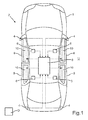
- Fig. 1 shows a motor vehicle 1 with a driver assistance system 2.
- the driver assistance system 2 which is also referred to as exit assistant, is used to support at least one person not shown here, which is located in an interior of the motor vehicle 1, when getting out of the vehicle 1.
- Das Augustassistenzsystem is intended in particular to prevent the at least one person from disembarking from the motor vehicle 1 from colliding with an object O which is located in a surrounding area U of the motor vehicle 1.
- the driver assistance system 2 here comprises a first vehicle-side sensor device 4, a second vehicle-side sensor device 6, a control device 8 and a lighting device 10.
- the lighting device 10 may be arranged for example in at least one vehicle door 9 of the motor vehicle 1 and a light strip by emitting light along a contour , For example, in an interior trim of the vehicle door 9, in the interior of the motor vehicle 1 generate.
- the control device 8 provides a first operating mode for the lighting device 10.
- the lighting device 10 fulfills an ambient function and emits light having a first wavelength and a first wavelength spectrum, respectively.
- the ambient function serves, for example, to emphasize or emphasize the contours in order to enable the occupants or persons in the interior of the motor vehicle 1, for example in the dark, to orient themselves in the interior of the motor vehicle 1.
- the first vehicle-side sensor device 4 may for example be arranged on exterior mirrors of the motor vehicle 1 and / or bumpers of the motor vehicle 1 and detect a distance of the object O in the peripheral region U of the motor vehicle 1 to the motor vehicle 1 in a parked state of the motor vehicle 1.
- the first sensor device 4 may include, for example, radar sensors. If the distance of the object O from the motor vehicle 1 falls below a predetermined minimum distance, then the person is threatening to collide with the object O when getting out of the motor vehicle 1. To prevent this collision, the control device 8 sets the sensor device 4 by the first vehicle-side sensor device 4 detected falls below the minimum distance a second operating mode for the lighting device 10 ready, in which the lighting device 10 performs a so-called assistance function.
- the illumination device 10 emits light having a second wavelength or a second wavelength spectrum.
- the second wavelength or the second wavelength spectrum is different from the first wavelength or the first wavelength spectrum. This means that the contour illuminates in a different color in the second operating mode than in the first operating mode.
- the second wavelength or the second wavelength spectrum can be selected in particular from a wavelength range between 630 nm and 790 nm. Thus, the light strip generated by the illumination device 10 thus shines red.
- control device 8 in the second operating mode provides a first operating stage for the illumination device 10, in which the illumination device 10 emits the light of the second wavelength at intervals.
- This first stage of operation serves as an information level for informing the at least one person about a possible collision with the object O when getting out of the motor vehicle 1.
- the controller 8 may provide a second operating level in the second operating mode for the lighting device 10, in which the lighting device 10 continuously emits the light of the second wavelength.
- the second operating stage a so-called warning stage, is provided by the control device 8 when it is detected by the second vehicle-side sensor device 6 that at least one of the vehicle doors 9 of the motor vehicle 1 is opened.
- the second vehicle-side sensor device 6 can detect, for example, whether the person actuates the inner door handle of the vehicle door 9 to open the vehicle door 9.
- an intensity or a light intensity of the emitted light in the second operating stage compared to the first operating stage can additionally be increased.
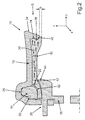
- Fig. 2 shows an embodiment of the illumination device 10 for generating the light strip along the contour, in particular in the vehicle door 9, in the interior of the motor vehicle 1 in a sectional side view. Since the illumination device 10 is shown in a cross-sectional view, the contour or the generated light strip extends here in the x direction into the plane of the drawing or out of the plane of the drawing.
- the lighting device 10 comprises a housing element 12, a light-conducting element 14, a diffuser 16 and a retaining element 18.
- the housing element 12 and the retaining element 18 form two parts of a multi-part housing.
- the light-guiding element 14, which is embodied, for example, as an elongate-shaped optical fiber, emits light 20 along the contour, in particular in the y-direction.
- the diffuser 16 is formed, for example, as a diffuser and made for example by means of an injection molding process as a tool falling component.
- the diffuser 16 has a coupling-in region 22, which extends in the x-direction and which is formed adjacent to the light-guiding element 14. In this coupling region 22, which is formed for example by a first end face of the lens is, the light emitted from the light guide 14 in the y direction light 20 is coupled.
- the light 20 is guided in the y-direction through the diffuser 16 to an outcoupling region 24 of the diffuser 16 opposite the coupling-in region 22.
- the decoupling region 24 points in the direction of the interior of the motor vehicle 1.
- the housing element 12 here has a channel-shaped recess 26, in which the light-guiding element 14 is arranged.
- the holding element 18 is mechanically, for example via a welded joint 28, connected to the housing element 12.
- the housing element 12 and the holding element 18 form a receiving space 30 for the light-guiding element 14 in that the holding element 18 covers the elongated, channel-shaped recess 26 here.
- the diffuser 16 is held by the housing member 12 and the holding member 18.
- the diffuser 16 for holding the diffuser 16 is arranged in regions in the receiving space 30 and is thus clamped between the holding member 18 and the housing member 12.
- the diffuser 16 Within the receiving area 30, the diffuser 16 has a curvature 32 along the contour in the x-direction, which surrounds the light-guiding element 14 at least in regions.
- the bulge 32 and the recess 26 thus form a tunnel or a channel along the x-direction, through which the light-guiding element 14 extends in the x-direction and thereby emits the light 20 in the y-direction.
- the region of the curvature 32 which lies opposite the decoupling region 24 in the negative y-direction, forms the coupling region 22 already described.
- a front region 34 of the housing element 12 covers the decoupling region 24 of the diffuser 16 in regions.
- a light exit surface 36 through which the light 20 leaves the coupling-out region 24 of the diffuser 16 into the interior of the motor vehicle 1, is reduced.
- the light exit surface 36 forms a strip, which preferably has a width b of less than 1 mm. In particular, the width b is between 0.3 mm and 0.8 mm.
- a first recess 38 in the decoupling region 24 of the diffuser 16 and a first elevation 40 corresponding to the first recess 38 are additionally provided in a side of the front region 34 of the housing element 12 facing the decoupling region 24.
- the first survey 40 is arranged to form a positive connection in the first recess 38.
- a second recess 42 is provided for holding the diffuser 16 in a side of the diffuser 16 facing the holding element 18, and a second elevation 44 corresponding to the second recess is provided on the holding element 18.
- the second survey 44 is arranged to form a positive connection in the second recess 42.
- a viewing area S of the lighting device 10 is visible, which includes the light exit surface 36 of the diffuser 16 and the front portion 34 of the housing element 12.
- the housing element 12, in particular the front region 34 of the housing element 12, can be coated with chromium along the contour.
- the housing member 12 also act as a trim part in the interior of the motor vehicle 1.
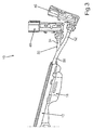
- Fig. 3 shows an embodiment of the illumination device 10 with a first light source 46 for emitting light of the first wavelength or the first wavelength spectrum in the first operating mode of the illumination device 10 and with a second light source for emitting light with the second wavelength or the second wavelength spectrum in the second operating mode of the illumination device 10.
- the first light source 46 and the second light source 28 may be configured, for example, as light-emitting diodes (LED) or LED modules.
- the illumination device 10 comprises a fork feed 50 with a first optical fiber or with a first strand 52, which is coupled to the first light source 46, a second optical fiber or a second strand 54, which is coupled to the second light source 48, and a third optical fiber or a third strand 56 which is coupled to the light guide element 14 of the illumination device 10, not shown here.
- the light of the first light source 46 is coupled into the light guide element 14 via the first strand 52 and the third strand 56 and the second light source 48 is supplied via the second light source 48 to provide the second operating mode Strand 54 and the third strand 56 coupled into the light guide 14.
- either the first operating mode and thus the ambient function or the second operating mode and thus the assistance function can be provided.
Landscapes
- Engineering & Computer Science (AREA)
- Mechanical Engineering (AREA)
- Human Computer Interaction (AREA)
- Arrangements Of Lighting Devices For Vehicle Interiors, Mounting And Supporting Thereof, Circuits Therefore (AREA)
- Lighting Device Outwards From Vehicle And Optical Signal (AREA)
Applications Claiming Priority (1)
| Application Number | Priority Date | Filing Date | Title |
|---|---|---|---|
| DE102015006425.8A DE102015006425A1 (de) | 2015-05-19 | 2015-05-19 | Fahrerassistenzsystem zum Unterstützen einer Person beim Aussteigen aus einem Kraftfahrzeug, Kraftfahrzeug sowie Verfahren |
Publications (3)
| Publication Number | Publication Date |
|---|---|
| EP3095643A2 true EP3095643A2 (fr) | 2016-11-23 |
| EP3095643A3 EP3095643A3 (fr) | 2017-02-08 |
| EP3095643B1 EP3095643B1 (fr) | 2018-09-19 |
Family
ID=55862613
Family Applications (1)
| Application Number | Title | Priority Date | Filing Date |
|---|---|---|---|
| EP16167587.1A Active EP3095643B1 (fr) | 2015-05-19 | 2016-04-29 | Systeme d'assistance au conducteur pour assister une personne lors de la descente d'un vehicule automobile, vehicule automobile et procede |
Country Status (2)
| Country | Link |
|---|---|
| EP (1) | EP3095643B1 (fr) |
| DE (1) | DE102015006425A1 (fr) |
Families Citing this family (5)
| Publication number | Priority date | Publication date | Assignee | Title |
|---|---|---|---|---|
| DE102016220931B4 (de) | 2016-10-25 | 2025-08-07 | Ford Global Technologies, Llc | Verfahren zum Beleuchten eines Fahrzeuginnenraums mittels verteilter Ambientenbeleuchtungen |
| DE102017217074A1 (de) | 2017-09-26 | 2019-03-28 | Volkswagen Aktiengesellschaft | Verfahren, Vorrichtung und computerlesbares Speichermedium mit Instruktionen zum Kennzeichnen einer Ausstiegsseite eines Kraftfahrzeugs |
| DE102023129439A1 (de) * | 2023-10-25 | 2025-04-30 | Dr. Ing. H.C. F. Porsche Aktiengesellschaft | Kraftfahrzeug mit Silhouettenbeleuchtung |
| DE102024002776A1 (de) | 2024-08-29 | 2026-03-05 | Mercedes-Benz Group AG | Lautsprecheranordnung für ein Fahrzeug und Fahrzeug |
| DE102024126470A1 (de) * | 2024-09-13 | 2026-03-19 | Man Truck & Bus Se | Fahrzeugtür für ein Kraftfahrzeug, aufweisend Beleuchtungseinrichtung |
Citations (3)
| Publication number | Priority date | Publication date | Assignee | Title |
|---|---|---|---|---|
| DE102006024194A1 (de) | 2005-05-25 | 2006-12-28 | GM Global Technology Operations, Inc., Detroit | Fahrzeugbeleuchtungssystem und -verfahren |
| DE102008064022A1 (de) | 2008-12-19 | 2009-09-17 | Daimler Ag | Anordnung und Verfahren zur Bereitstellung von gefahrensituationsabhängigen Warninformationen |
| DE102012015753A1 (de) | 2012-08-08 | 2014-02-13 | Daimler Ag | Ansteuern einer Innenraumbeleuchtungsvorrichtung zum Warnen eines Nutzers eines Kraftfahrzeugs vor einer Kollisionsgefahr |
Family Cites Families (7)
| Publication number | Priority date | Publication date | Assignee | Title |
|---|---|---|---|---|
| DE10312252A1 (de) * | 2003-03-19 | 2004-09-30 | Siemens Ag | Verfahren und Vorrichtung zur Vermeidung von Personen- und Sachschäden durch Kraftfahrzeugtüren |
| DE102011015103B4 (de) * | 2011-03-25 | 2015-07-16 | Audi Ag | Leuchtvorrichtung für ein Kraftfahrzeug und Fahrerassistenzsystem mit dieser Leuchtvorrichtung |
| DE102011076340A1 (de) * | 2011-05-24 | 2012-11-29 | Robert Bosch Gmbh | Verfahren und Vorrichtung zum Warnen von Verkehrsteilnehmern |
| DE102011086215A1 (de) * | 2011-11-11 | 2013-05-16 | Robert Bosch Gmbh | Verfahren zur Unterstützung eines Fahrers eines Kraftfahrzeugs |
| DE102011121616A1 (de) * | 2011-12-20 | 2013-06-20 | Audi Ag | Verfahren zur Ansteuerung einerAnzeigeeinrichtung eines Kraftfahrzeugs |
| DE102012014939A1 (de) * | 2012-07-27 | 2014-01-30 | Volkswagen Aktiengesellschaft | Verfahren und Vorrichtung zur Kollisionsvermeidung |
| DE102013005018A1 (de) * | 2013-03-22 | 2013-09-19 | Daimler Ag | Kraftfahrzeug mit Türkollisionswarnvorrichtung und Türkollisionswarnverfahren |
-
2015
- 2015-05-19 DE DE102015006425.8A patent/DE102015006425A1/de not_active Withdrawn
-
2016
- 2016-04-29 EP EP16167587.1A patent/EP3095643B1/fr active Active
Patent Citations (3)
| Publication number | Priority date | Publication date | Assignee | Title |
|---|---|---|---|---|
| DE102006024194A1 (de) | 2005-05-25 | 2006-12-28 | GM Global Technology Operations, Inc., Detroit | Fahrzeugbeleuchtungssystem und -verfahren |
| DE102008064022A1 (de) | 2008-12-19 | 2009-09-17 | Daimler Ag | Anordnung und Verfahren zur Bereitstellung von gefahrensituationsabhängigen Warninformationen |
| DE102012015753A1 (de) | 2012-08-08 | 2014-02-13 | Daimler Ag | Ansteuern einer Innenraumbeleuchtungsvorrichtung zum Warnen eines Nutzers eines Kraftfahrzeugs vor einer Kollisionsgefahr |
Also Published As
| Publication number | Publication date |
|---|---|
| DE102015006425A1 (de) | 2016-11-24 |
| EP3095643B1 (fr) | 2018-09-19 |
| EP3095643A3 (fr) | 2017-02-08 |
Similar Documents
| Publication | Publication Date | Title |
|---|---|---|
| EP3095643B1 (fr) | Systeme d'assistance au conducteur pour assister une personne lors de la descente d'un vehicule automobile, vehicule automobile et procede | |
| EP3781439B1 (fr) | Procédé permettant la communication d'un véhicule à moteur avec un usager de la route et véhicule à moteur pour mettre en oeuvre ledit procédé | |
| DE102018206087B4 (de) | Verfahren zur Kommunikation eines Kraftfahrzeugs mit einem Verkehrsteilnehmer sowie Kraftfahrzeug zur Durchführung des Verfahrens | |
| EP3781438B1 (fr) | Procédé de communication d'un véhicule automobile avec un usager de la route et véhicule automobile déstiné à la mise en uvre de ce procédé | |
| WO2015067353A2 (fr) | Véhicule équipé d'une installation d'éclairage comportant un appareil d'éclairage de forme allongée | |
| WO2017144247A1 (fr) | Véhicule à moteur doté d'un dispositif d'éclairage périphérique | |
| WO2016184721A1 (fr) | Feu de signalisation pour véhicules | |
| WO2005101092A1 (fr) | Dispositif de signalisation servant a afficher des indications de type avertissements et/ou informations dans des vehicules | |
| WO2014090563A1 (fr) | Dispositif d'éclairage pour un véhicule automobile | |
| DE102013001276A1 (de) | Verfahren zur Steuerung eines Abbiegelichts in einem Kraftfahrzeug | |
| DE102016004259A1 (de) | Einparkunterstützungssystem | |
| DE102015009442A1 (de) | Sicherheitssystem für ein Fahrzeug mit nicht einsehbaren Umgebungsbereichen | |
| EP3025908A1 (fr) | Dispositif comprenant un capteur de mouvement exterieur et balise lumineuse pour un vehicule automobile | |
| DE102011106838A1 (de) | Außenrückspiegel mit Leuchtanzeige und Verfahren zur Darstellung kritischer Verkehrssituationen | |
| DE102015109932A1 (de) | Warnvorrichtung für ein Kraftfahrzeug mit außen angeordneter Anzeigeeinrichtung sowie Kraftfahrzeug | |
| DE102018207618A1 (de) | Lichtemittierende Vorrichtung für Fahrzeuge | |
| DE102016001201B4 (de) | Kraftfahrzeug | |
| WO2016037725A1 (fr) | Caméra de véhicule automobile | |
| DE102017007761A1 (de) | Vorrichtung zur kamerabasierten Umgebungserfassung für ein Fahrzeug und Steuerungsverfahren hierfür | |
| DE102015006426B4 (de) | Beleuchtungseinrichtung zum Erzeugen eines schmalen Lichtstreifens in einem Innenraum eines Kraftfahrzeugs sowie Kraftfahrzeug | |
| WO2023280523A1 (fr) | Dispositif d'éclairage pour l'extérieur d'un véhicule automobile | |
| WO2015150026A1 (fr) | Dispositif d'émission d'une information optique sur un véhicule automobile | |
| DE102015207938A1 (de) | Verfahren zur Steuerung einer Leuchtintensität von Bremslichtern | |
| EP4117966B1 (fr) | Véhicule automobile | |
| DE102005042675B4 (de) | Beleuchtungsanordnung für Fahrzeuge |
Legal Events
| Date | Code | Title | Description |
|---|---|---|---|
| PUAI | Public reference made under article 153(3) epc to a published international application that has entered the european phase |
Free format text: ORIGINAL CODE: 0009012 |
|
| AK | Designated contracting states |
Kind code of ref document: A2 Designated state(s): AL AT BE BG CH CY CZ DE DK EE ES FI FR GB GR HR HU IE IS IT LI LT LU LV MC MK MT NL NO PL PT RO RS SE SI SK SM TR |
|
| AX | Request for extension of the european patent |
Extension state: BA ME |
|
| PUAL | Search report despatched |
Free format text: ORIGINAL CODE: 0009013 |
|
| AK | Designated contracting states |
Kind code of ref document: A3 Designated state(s): AL AT BE BG CH CY CZ DE DK EE ES FI FR GB GR HR HU IE IS IT LI LT LU LV MC MK MT NL NO PL PT RO RS SE SI SK SM TR |
|
| AX | Request for extension of the european patent |
Extension state: BA ME |
|
| RIC1 | Information provided on ipc code assigned before grant |
Ipc: B60Q 9/00 20060101ALI20170103BHEP Ipc: B60Q 3/02 00000000AFI20170103BHEP |
|
| STAA | Information on the status of an ep patent application or granted ep patent |
Free format text: STATUS: REQUEST FOR EXAMINATION WAS MADE |
|
| 17P | Request for examination filed |
Effective date: 20170808 |
|
| RBV | Designated contracting states (corrected) |
Designated state(s): AL AT BE BG CH CY CZ DE DK EE ES FI FR GB GR HR HU IE IS IT LI LT LU LV MC MK MT NL NO PL PT RO RS SE SI SK SM TR |
|
| RAP1 | Party data changed (applicant data changed or rights of an application transferred) |
Owner name: HELLA GMBH & CO. KGAA Owner name: AUDI AG |
|
| REG | Reference to a national code |
Ref country code: DE Ref legal event code: R079 Ref document number: 502016001992 Country of ref document: DE Free format text: PREVIOUS MAIN CLASS: B60Q0003020000 Ipc: B60Q0003000000 |
|
| RIC1 | Information provided on ipc code assigned before grant |
Ipc: B60Q 3/00 20060101AFI20180411BHEP |
|
| GRAP | Despatch of communication of intention to grant a patent |
Free format text: ORIGINAL CODE: EPIDOSNIGR1 |
|
| STAA | Information on the status of an ep patent application or granted ep patent |
Free format text: STATUS: GRANT OF PATENT IS INTENDED |
|
| INTG | Intention to grant announced |
Effective date: 20180522 |
|
| GRAS | Grant fee paid |
Free format text: ORIGINAL CODE: EPIDOSNIGR3 |
|
| GRAA | (expected) grant |
Free format text: ORIGINAL CODE: 0009210 |
|
| STAA | Information on the status of an ep patent application or granted ep patent |
Free format text: STATUS: THE PATENT HAS BEEN GRANTED |
|
| AK | Designated contracting states |
Kind code of ref document: B1 Designated state(s): AL AT BE BG CH CY CZ DE DK EE ES FI FR GB GR HR HU IE IS IT LI LT LU LV MC MK MT NL NO PL PT RO RS SE SI SK SM TR |
|
| REG | Reference to a national code |
Ref country code: GB Ref legal event code: FG4D Free format text: NOT ENGLISH |
|
| REG | Reference to a national code |
Ref country code: CH Ref legal event code: EP |
|
| REG | Reference to a national code |
Ref country code: AT Ref legal event code: REF Ref document number: 1042879 Country of ref document: AT Kind code of ref document: T Effective date: 20181015 |
|
| REG | Reference to a national code |
Ref country code: IE Ref legal event code: FG4D Free format text: LANGUAGE OF EP DOCUMENT: GERMAN |
|
| REG | Reference to a national code |
Ref country code: DE Ref legal event code: R096 Ref document number: 502016001992 Country of ref document: DE |
|
| REG | Reference to a national code |
Ref country code: NL Ref legal event code: MP Effective date: 20180919 |
|
| PG25 | Lapsed in a contracting state [announced via postgrant information from national office to epo] |
Ref country code: RS Free format text: LAPSE BECAUSE OF FAILURE TO SUBMIT A TRANSLATION OF THE DESCRIPTION OR TO PAY THE FEE WITHIN THE PRESCRIBED TIME-LIMIT Effective date: 20180919 Ref country code: LT Free format text: LAPSE BECAUSE OF FAILURE TO SUBMIT A TRANSLATION OF THE DESCRIPTION OR TO PAY THE FEE WITHIN THE PRESCRIBED TIME-LIMIT Effective date: 20180919 Ref country code: SE Free format text: LAPSE BECAUSE OF FAILURE TO SUBMIT A TRANSLATION OF THE DESCRIPTION OR TO PAY THE FEE WITHIN THE PRESCRIBED TIME-LIMIT Effective date: 20180919 Ref country code: BG Free format text: LAPSE BECAUSE OF FAILURE TO SUBMIT A TRANSLATION OF THE DESCRIPTION OR TO PAY THE FEE WITHIN THE PRESCRIBED TIME-LIMIT Effective date: 20181219 Ref country code: GR Free format text: LAPSE BECAUSE OF FAILURE TO SUBMIT A TRANSLATION OF THE DESCRIPTION OR TO PAY THE FEE WITHIN THE PRESCRIBED TIME-LIMIT Effective date: 20181220 Ref country code: FI Free format text: LAPSE BECAUSE OF FAILURE TO SUBMIT A TRANSLATION OF THE DESCRIPTION OR TO PAY THE FEE WITHIN THE PRESCRIBED TIME-LIMIT Effective date: 20180919 Ref country code: NO Free format text: LAPSE BECAUSE OF FAILURE TO SUBMIT A TRANSLATION OF THE DESCRIPTION OR TO PAY THE FEE WITHIN THE PRESCRIBED TIME-LIMIT Effective date: 20181219 |
|
| REG | Reference to a national code |
Ref country code: LT Ref legal event code: MG4D |
|
| PG25 | Lapsed in a contracting state [announced via postgrant information from national office to epo] |
Ref country code: HR Free format text: LAPSE BECAUSE OF FAILURE TO SUBMIT A TRANSLATION OF THE DESCRIPTION OR TO PAY THE FEE WITHIN THE PRESCRIBED TIME-LIMIT Effective date: 20180919 Ref country code: LV Free format text: LAPSE BECAUSE OF FAILURE TO SUBMIT A TRANSLATION OF THE DESCRIPTION OR TO PAY THE FEE WITHIN THE PRESCRIBED TIME-LIMIT Effective date: 20180919 Ref country code: AL Free format text: LAPSE BECAUSE OF FAILURE TO SUBMIT A TRANSLATION OF THE DESCRIPTION OR TO PAY THE FEE WITHIN THE PRESCRIBED TIME-LIMIT Effective date: 20180919 |
|
| PG25 | Lapsed in a contracting state [announced via postgrant information from national office to epo] |
Ref country code: IS Free format text: LAPSE BECAUSE OF FAILURE TO SUBMIT A TRANSLATION OF THE DESCRIPTION OR TO PAY THE FEE WITHIN THE PRESCRIBED TIME-LIMIT Effective date: 20190119 Ref country code: NL Free format text: LAPSE BECAUSE OF FAILURE TO SUBMIT A TRANSLATION OF THE DESCRIPTION OR TO PAY THE FEE WITHIN THE PRESCRIBED TIME-LIMIT Effective date: 20180919 Ref country code: ES Free format text: LAPSE BECAUSE OF FAILURE TO SUBMIT A TRANSLATION OF THE DESCRIPTION OR TO PAY THE FEE WITHIN THE PRESCRIBED TIME-LIMIT Effective date: 20180919 Ref country code: EE Free format text: LAPSE BECAUSE OF FAILURE TO SUBMIT A TRANSLATION OF THE DESCRIPTION OR TO PAY THE FEE WITHIN THE PRESCRIBED TIME-LIMIT Effective date: 20180919 Ref country code: IT Free format text: LAPSE BECAUSE OF FAILURE TO SUBMIT A TRANSLATION OF THE DESCRIPTION OR TO PAY THE FEE WITHIN THE PRESCRIBED TIME-LIMIT Effective date: 20180919 Ref country code: CZ Free format text: LAPSE BECAUSE OF FAILURE TO SUBMIT A TRANSLATION OF THE DESCRIPTION OR TO PAY THE FEE WITHIN THE PRESCRIBED TIME-LIMIT Effective date: 20180919 Ref country code: RO Free format text: LAPSE BECAUSE OF FAILURE TO SUBMIT A TRANSLATION OF THE DESCRIPTION OR TO PAY THE FEE WITHIN THE PRESCRIBED TIME-LIMIT Effective date: 20180919 Ref country code: PL Free format text: LAPSE BECAUSE OF FAILURE TO SUBMIT A TRANSLATION OF THE DESCRIPTION OR TO PAY THE FEE WITHIN THE PRESCRIBED TIME-LIMIT Effective date: 20180919 |
|
| PG25 | Lapsed in a contracting state [announced via postgrant information from national office to epo] |
Ref country code: PT Free format text: LAPSE BECAUSE OF FAILURE TO SUBMIT A TRANSLATION OF THE DESCRIPTION OR TO PAY THE FEE WITHIN THE PRESCRIBED TIME-LIMIT Effective date: 20190119 Ref country code: SM Free format text: LAPSE BECAUSE OF FAILURE TO SUBMIT A TRANSLATION OF THE DESCRIPTION OR TO PAY THE FEE WITHIN THE PRESCRIBED TIME-LIMIT Effective date: 20180919 Ref country code: SK Free format text: LAPSE BECAUSE OF FAILURE TO SUBMIT A TRANSLATION OF THE DESCRIPTION OR TO PAY THE FEE WITHIN THE PRESCRIBED TIME-LIMIT Effective date: 20180919 |
|
| REG | Reference to a national code |
Ref country code: DE Ref legal event code: R097 Ref document number: 502016001992 Country of ref document: DE |
|
| PLBE | No opposition filed within time limit |
Free format text: ORIGINAL CODE: 0009261 |
|
| STAA | Information on the status of an ep patent application or granted ep patent |
Free format text: STATUS: NO OPPOSITION FILED WITHIN TIME LIMIT |
|
| PG25 | Lapsed in a contracting state [announced via postgrant information from national office to epo] |
Ref country code: DK Free format text: LAPSE BECAUSE OF FAILURE TO SUBMIT A TRANSLATION OF THE DESCRIPTION OR TO PAY THE FEE WITHIN THE PRESCRIBED TIME-LIMIT Effective date: 20180919 |
|
| 26N | No opposition filed |
Effective date: 20190620 |
|
| PG25 | Lapsed in a contracting state [announced via postgrant information from national office to epo] |
Ref country code: SI Free format text: LAPSE BECAUSE OF FAILURE TO SUBMIT A TRANSLATION OF THE DESCRIPTION OR TO PAY THE FEE WITHIN THE PRESCRIBED TIME-LIMIT Effective date: 20180919 |
|
| REG | Reference to a national code |
Ref country code: CH Ref legal event code: PL |
|
| REG | Reference to a national code |
Ref country code: BE Ref legal event code: MM Effective date: 20190430 |
|
| PG25 | Lapsed in a contracting state [announced via postgrant information from national office to epo] |
Ref country code: LU Free format text: LAPSE BECAUSE OF NON-PAYMENT OF DUE FEES Effective date: 20190429 Ref country code: MC Free format text: LAPSE BECAUSE OF FAILURE TO SUBMIT A TRANSLATION OF THE DESCRIPTION OR TO PAY THE FEE WITHIN THE PRESCRIBED TIME-LIMIT Effective date: 20180919 |
|
| PG25 | Lapsed in a contracting state [announced via postgrant information from national office to epo] |
Ref country code: LI Free format text: LAPSE BECAUSE OF NON-PAYMENT OF DUE FEES Effective date: 20190430 Ref country code: CH Free format text: LAPSE BECAUSE OF NON-PAYMENT OF DUE FEES Effective date: 20190430 |
|
| PG25 | Lapsed in a contracting state [announced via postgrant information from national office to epo] |
Ref country code: BE Free format text: LAPSE BECAUSE OF NON-PAYMENT OF DUE FEES Effective date: 20190430 |
|
| PG25 | Lapsed in a contracting state [announced via postgrant information from national office to epo] |
Ref country code: TR Free format text: LAPSE BECAUSE OF FAILURE TO SUBMIT A TRANSLATION OF THE DESCRIPTION OR TO PAY THE FEE WITHIN THE PRESCRIBED TIME-LIMIT Effective date: 20180919 |
|
| PG25 | Lapsed in a contracting state [announced via postgrant information from national office to epo] |
Ref country code: IE Free format text: LAPSE BECAUSE OF NON-PAYMENT OF DUE FEES Effective date: 20190429 |
|
| PG25 | Lapsed in a contracting state [announced via postgrant information from national office to epo] |
Ref country code: CY Free format text: LAPSE BECAUSE OF FAILURE TO SUBMIT A TRANSLATION OF THE DESCRIPTION OR TO PAY THE FEE WITHIN THE PRESCRIBED TIME-LIMIT Effective date: 20180919 |
|
| PG25 | Lapsed in a contracting state [announced via postgrant information from national office to epo] |
Ref country code: MT Free format text: LAPSE BECAUSE OF FAILURE TO SUBMIT A TRANSLATION OF THE DESCRIPTION OR TO PAY THE FEE WITHIN THE PRESCRIBED TIME-LIMIT Effective date: 20180919 Ref country code: HU Free format text: LAPSE BECAUSE OF FAILURE TO SUBMIT A TRANSLATION OF THE DESCRIPTION OR TO PAY THE FEE WITHIN THE PRESCRIBED TIME-LIMIT; INVALID AB INITIO Effective date: 20160429 |
|
| REG | Reference to a national code |
Ref country code: AT Ref legal event code: MM01 Ref document number: 1042879 Country of ref document: AT Kind code of ref document: T Effective date: 20210429 |
|
| PG25 | Lapsed in a contracting state [announced via postgrant information from national office to epo] |
Ref country code: MK Free format text: LAPSE BECAUSE OF FAILURE TO SUBMIT A TRANSLATION OF THE DESCRIPTION OR TO PAY THE FEE WITHIN THE PRESCRIBED TIME-LIMIT Effective date: 20180919 |
|
| PG25 | Lapsed in a contracting state [announced via postgrant information from national office to epo] |
Ref country code: AT Free format text: LAPSE BECAUSE OF NON-PAYMENT OF DUE FEES Effective date: 20210429 |
|
| P01 | Opt-out of the competence of the unified patent court (upc) registered |
Effective date: 20230530 |
|
| PGFP | Annual fee paid to national office [announced via postgrant information from national office to epo] |
Ref country code: DE Payment date: 20250425 Year of fee payment: 10 |
|
| PGFP | Annual fee paid to national office [announced via postgrant information from national office to epo] |
Ref country code: GB Payment date: 20250423 Year of fee payment: 10 |
|
| PGFP | Annual fee paid to national office [announced via postgrant information from national office to epo] |
Ref country code: FR Payment date: 20250422 Year of fee payment: 10 |