EP3095653B1 - Hauptzylinderbetätigungsmechanismus - Google Patents
Hauptzylinderbetätigungsmechanismus Download PDFInfo
- Publication number
- EP3095653B1 EP3095653B1 EP16160989.6A EP16160989A EP3095653B1 EP 3095653 B1 EP3095653 B1 EP 3095653B1 EP 16160989 A EP16160989 A EP 16160989A EP 3095653 B1 EP3095653 B1 EP 3095653B1
- Authority
- EP
- European Patent Office
- Prior art keywords
- guiding member
- cylinder body
- dashboard
- pushrod
- master cylinder
- Prior art date
- Legal status (The legal status is an assumption and is not a legal conclusion. Google has not performed a legal analysis and makes no representation as to the accuracy of the status listed.)
- Not-in-force
Links
- 230000033001 locomotion Effects 0.000 claims description 6
- 238000006073 displacement reaction Methods 0.000 description 7
- 230000000994 depressogenic effect Effects 0.000 description 3
- 239000012530 fluid Substances 0.000 description 2
- 230000002093 peripheral effect Effects 0.000 description 2
- 230000005540 biological transmission Effects 0.000 description 1
- 230000000881 depressing effect Effects 0.000 description 1
- 238000010586 diagram Methods 0.000 description 1
Images

Classifications
-
- B—PERFORMING OPERATIONS; TRANSPORTING
- B60—VEHICLES IN GENERAL
- B60T—VEHICLE BRAKE CONTROL SYSTEMS OR PARTS THEREOF; BRAKE CONTROL SYSTEMS OR PARTS THEREOF, IN GENERAL; ARRANGEMENT OF BRAKING ELEMENTS ON VEHICLES IN GENERAL; PORTABLE DEVICES FOR PREVENTING UNWANTED MOVEMENT OF VEHICLES; VEHICLE MODIFICATIONS TO FACILITATE COOLING OF BRAKES
- B60T11/00—Transmitting braking action from initiating means to ultimate brake actuator without power assistance or drive or where such assistance or drive is irrelevant
- B60T11/10—Transmitting braking action from initiating means to ultimate brake actuator without power assistance or drive or where such assistance or drive is irrelevant transmitting by fluid means, e.g. hydraulic
- B60T11/16—Master control, e.g. master cylinders
- B60T11/18—Connection thereof to initiating means
Definitions
- the disclosure relates generally to a master cylinder operating mechanism, and more specifically to a master cylinder operating mechanism including a stopper provided in a master cylinder.
- a hydraulically-operated system mounted in a vehicle such as a clutch mechanism or a brake mechanism
- an operating force is transmitted to a master cylinder from an operation pedal operated by a driver, and the operating force is converted into a hydraulic operating force by the hydraulic pressure in the master cylinder.
- a lever on the operation pedal side is connected to a pushrod that inputs the operating force into the master cylinder.
- the master cylinder operating mechanism is configured such that a guiding member that guides a piston is fitted to an opening end of a cylinder body.
- the cylinder body of the master cylinder operating mechanism is secured to a dashboard of a vehicle with a bolt.
- JP S59 190663 discloses a master cylinder operating mechanism.
- US 2009/0179485 discloses a vehicle brake device of an electronic hydraulic brake system.
- the vehicle brake device of an electronic hydraulic brake system includes an input shaft coupled to a brake pedal, a pedal operation detector which detects pedal force of a driver, a pedal simulator coupled to the input shaft in a control housing to supply pedal repulsive force, a master cylinder which delivers a hydraulic pressure to a wheel brake when a braking pressure is formed by the brake pedal, a control piston which is adjacent to a first piston of the master cylinder to deliver a hydraulic pressure to the first piston, a control chamber which controls a pressure of the master cylinder between the control piston and the pedal simulator, and a hydraulic pressure supply which delivers a hydraulic pressure to the control chamber as required by a driver, wherein the pedal simulator includes a pedal simulator piston which slidably moves in the control housing, a pressing member which reciprocates corresponding to reciprocating motion of the input shaft in the pedal simulator piston, a simulator piston provided in the pedal simulator piston to slidably move corresponding to movement of the pressing member
- a sliding motion of the piston in response to the operation of a clutch pedal is restricted by a stopper provided on the inner side of the guiding member.
- the stopper restricts a sliding motion of the piston in a direction in which the piston comes out of the cylinder body
- the guiding member receives a load that acts in a direction in which the guiding member moves away from the cylinder body.
- the guiding member may be disconnected from the cylinder body.
- the disclosure provides a master cylinder operating mechanism configured to inhibit a guiding member from being disconnected from a cylinder body.
- the invention concerns a vehicle according to claim 1 and comprising a master cylinder operating mechanism.
- the master cylinder operating mechanism includes a cylinder body, a guiding member, a piston, a pushrod, and a stopper member.
- the cylinder body has an opening, and the opening is at one end of the cylinder body.
- the guiding member is engaged with the opening of the cylinder body, and the guiding member is a member different from the cylinder body (i.e., a member that is prepared separately from the cylinder body).
- the piston is slidably accommodated inside the cylinder body and the guiding member.
- the pushrod is connected to an end portion of the piston, and the pushrod is configured to slide the piston in response to a pedal operating force generated by a driver.
- the stopper member is provided on an inner side of the guiding member.
- the stopper member is configured to restrict a sliding motion of the piston by coming into contact with the pushrod when the pushrod slides in a direction in which the pushrod is pulled out of the guiding member.
- a surface of the guiding member is in contact with a dashboard of the vehicle.
- the dashboard separates the engine compartment and a vehicle cabin from each other. The surface of the guiding member in contact with the dashboard faces the engine compartment-side surface of the dashboard in the direction in which the pushrod is pulled out of the guiding member.
- the guiding member receives a load that acts in a direction in which the pushrod is pulled out of the guiding member.
- the surface of the guiding member is in contact with the dashboard, and the surface of the guiding member in contact with the dashboard faces the engine compartment-side surface of the dashboard in the direction in which the pushrod is pulled out of the guiding member.
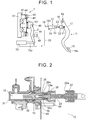
- FIG. 1 and FIG. 2 illustrate the schematic configuration of a vehicle clutch provided with a master cylinder operating mechanism according to a disclosed embodiment.
- the vehicle clutch of the present embodiment is configured such that a hydraulically-operated clutch mechanism 1, which is a friction clutch, is operated in response to a depressing operation of a clutch pedal 11 that is pivotally displaced within a displaceable range.
- An operation system for the vehicle clutch includes the clutch pedal 11, a master cylinder 12, and a release cylinder 13.
- the master cylinder 12 generates a hydraulic pressure corresponding to the degree to which the clutch pedal 11 is depressed, and then supplies the hydraulic pressure to the hydraulically-operated clutch mechanism 1.
- the release cylinder 13 is operated in response to the hydraulic pressure from the master cylinder 12, thereby operating a release fork 2 of the hydraulically-operated clutch mechanism 1.
- the master cylinder operating mechanism according to the present embodiment is disposed within a region from the clutch pedal 11 to the master cylinder 12.
- the clutch pedal 11 is an assembly of a support shaft 16, a lever 17, and a pedal 18.
- the support shaft 16 is rotatably supported by a support member 19 on the vehicle body side.
- the lever 17 is connected to the support shaft 16.
- the pedal 18 is secured to an end of the lever 17.
- the lever 17 has a generally rectangular sectional shape.
- the lever 17 is supported by the support shaft 16 with the direction of the long sides of the generally rectangular section being parallel to the vehicle front-rear direction.
- the pedal 18 is provided at the end of the lever 17, and has a tread surface 18a to be depressed by a driver.
- a base end side portion of the lever 17 is supported via the support shaft 16 by the support member 19 on the vehicle body side, such that the lever 17 is pivotable in the vehicle-height direction and the vehicle front-rear direction.
- the lever 17 is configured to input, at its intermediate portion, an operating force into the master cylinder 12 via a clevis pin 21, a clevis 22, and a pushrod 23.
- the master cylinder 12 is configured in the following manner.
- a piston 32 is accommodated in a cylinder body 31 pivotably supported via a pin 12a by the support member 19 on the vehicle body side.
- the pushrod 23 is engaged with a rod portion 32a fitted in an end portion of the piston 32.
- the rod portion 32a is in the form of a clip.
- the master cylinder 12 pressurizes the hydraulic fluid in a pressurizing chamber 15 defined between the cylinder body 31 and the piston 32, and outputs the hydraulic pressure toward the release cylinder 13 through a clutch tube 33.
- the hydraulically-operated clutch mechanism 1 is configured in the following manner.
- a clutch disc 41 spline-fitted to a transmission input shaft (not illustrated) faces a flywheel 51 and the clutch disc 41 is covered, from its rear surface side, with a clutch cover 42.
- a diaphragm spring 43 held by the clutch cover 42 presses, at its outer peripheral portion, the clutch disc 41 via a pressure plate 44, thereby pressing the clutch disc 41 against the flywheel 51.
- the pressure plate 44 is supported by the clutch cover 42 so as to be movable in the axial direction.
- the release fork 2 is turnably supported by a housing 48 via a support pin 46.
- the central portion of the diaphragm spring 43 is pressed toward the flywheel 51 via a release bearing 45.
- the diaphragm spring 43 is subjected to an engagement cancellation (disengagement) operation from the release cylinder 13 side via the release bearing 45, the diaphragm spring 43 deflects such that the outer peripheral portion thereof moves away from the flywheel 51. In this way, the pressure plate 44 stops pressing the clutch disc 41 against the flywheel 51.
- the diaphragm spring 43 is supported by the clutch cover 42 via a pivot ring 47 at a prescribed radial position, and thus the diaphragm spring 43 is deflected about the pivot ring 47 in the axial direction or returns to its original shape obtained immediately after the assembly.
- a guiding member 36 fitted to the cylinder body 31 has an operating hole 36h in which the rod portion 32a of the piston 32 slides.
- a stopper member 35 having a cylindrical shape is provided in the operating hole 36h so as to be integral with the guiding member 36. The stopper member 35 restricts displacement of the pushrod 23 by coming into contact with the pushrod 23.
- the cylinder body 31 and the guiding member 36 each have a cylindrical shape such that the piston 32 fitted to the pushrod 23 is allowed to slide inside the cylinder body 31 and the guiding member 36. Further, the cylinder body 31 and the guiding member 36 are liquid-tight, so that displacement of the piston 32 pressurizes the hydraulic fluid inside the pressurizing chamber 15 defined between the cylinder body 31 and the piston 32.
- the guiding member 36 is welded to the cylinder body 31 with the guiding member 36 accommodated in the cylinder body 31.
- a welded area 10 where the guiding member 36 and the cylinder body 31 are welded to each other may be a plurality of steps as illustrated in FIG. 2 .
- the cylinder body 31 is secured with a bolt 49 and a nut 50.
- the bolt 49 passes through the dashboard 40 from an engine compartment into a vehicle cabin.
- the dashboard 40 has a through-hole through which the master cylinder 12 is passed.
- the master cylinder 12 is secured while being passed through the dashboard 40.
- the diameter of a surface of the guiding member 36 at which the guiding member 36 is in contact with the dashboard 40 is greater than the diameter of the through-hole of the dashboard 40 through which the master cylinder 12 is passed.
- the guiding member 36 is configured to be brought into contact with the dashboard 40.
- the stopper function of stopping the master cylinder 12 is carried out when the pushrod 23 that operates the master cylinder 12 is displaced in response to an operational input from the clutch pedal 11. That is, in the present embodiment, when the clutch pedal 11 is operated in the clutch engaging direction to engage the hydraulically-operated clutch mechanism 1, a stopper member 23s of the pushrod 23 comes into contact with the stopper member 35 provided on the inner side of the guiding member 36, thereby restricting displacement of the pushrod 23.
- the guiding member 36 when the stopper member 23s of the pushrod 23 comes into contact with the stopper member 35 provided on the inner side of the guiding member 36, the guiding member 36 receives a load that acts in a direction in which the pushrod 23 comes out of the cylinder body 31.
- the contact of the dashboard 40 with the guiding member 36 restricts displacement of the guiding member 36. In this way, displacement of the guiding member 36 in a direction in which the guiding member 36 comes out of the cylinder body 31 is restricted, so that the guiding member 36 is inhibited from being disconnected from the cylinder body 31.
- a clearance is provided between the dashboard 40 and the cylinder body 31, as illustrated in FIG. 3 .
- the distance between the dashboard 40 and the cylinder body 31 is set to such a distance that a collision between the dashboard 40 and the cylinder body 31 is prevented when the stopper member 23s of the pushrod 23 comes into contact with the stopper member 35 provided on the inner side of the guiding member 36 and the dashboard 40 is deformed due to a load received from the guiding member 36.
- the dashboard 40 and the cylinder body 31 come into contact with each other due to deformation of the dashboard 40, a load is applied from the dashboard 40 to the cylinder body 31 in a direction opposite to the direction in which a load is transmitted from the guiding member 36 to the dashboard 40, and thus the guiding member 36 is disconnected from the cylinder body 31.
Landscapes
- Engineering & Computer Science (AREA)
- Transportation (AREA)
- Mechanical Engineering (AREA)
- Hydraulic Clutches, Magnetic Clutches, Fluid Clutches, And Fluid Joints (AREA)
- Transmission Of Braking Force In Braking Systems (AREA)
Claims (1)
- Fahrzeug, umfassend einen Motor, der in einem Motorraum angeordnet ist, ein Armaturenbrett (40) und einen im Fahrzeug bereitgestellten Hauptzylinder-Betätigungsmechanismus, wobei der Hauptzylinder-Betätigungsmechanismus Folgendes umfasst:einen Zylinderkörper (31) mit einer Öffnung, wobei die Öffnung an einem Ende des Zylinderkörpers (31) ist;ein Führungselement (36), das mit der Öffnung des Zylinderkörpers (31) in Eingriff ist, wobei das Führungselement (36) ein Element ist, das sich vom Zylinderkörper (31) unterscheidet;einen Kolben (32), der verschiebbar im Inneren des Zylinderkörpers (31) und des Führungselements (36) untergebracht ist;eine Schubstrebe (23), die mit einem Endabschnitt des Kolbens (32) verbunden ist, wobei die Schubstrebe (23) konfiguriert ist, den Kolben (32) als Reaktion auf eine durch einen Fahrer erzeugte Pedalbetätigungskraft zu verschieben; undein Anschlagelement (35), das an einer Innenseite des Führungselements (36) bereitgestellt ist, wobei das Anschlagelement (35) konfiguriert ist, eine Verschiebebewegung des Kolbens (32) durch Inkontaktkommen mit der Schubstrebe (23) einzuschränken, wenn sich die Schubstrebe (23) in eine Richtung verschiebt, in die die Schubstrebe (23) aus dem Führungselement (36) gezogen wird; undwobei eine Oberfläche des Führungselements (36) in Kontakt mit dem Armaturenbrett (40) des Fahrzeugs ist, wobei das Armaturenbrett (40) den Motorraum und eine Fahrzeugkabine voneinander trennt, und die Oberfläche des Führungselements (36) in Kontakt mit dem Armaturenbrett (40) der Motorraum-seitigen Oberfläche des Armaturenbretts (40) in die Richtung zugewandt ist, in die die Schubstrebe (23) aus dem Führungselement (36) gezogen wird; dadurch gekennzeichnet, dass der Zylinderkörper (2) an dem Armaturenbrett (40) mit einem Abstand zwischen dem Armaturenbrett (40) und dem Zylinderkörper (31) befestigt ist.
Applications Claiming Priority (1)
| Application Number | Priority Date | Filing Date | Title |
|---|---|---|---|
| JP2015056950A JP6222149B2 (ja) | 2015-03-19 | 2015-03-19 | マスタシリンダの操作機構 |
Publications (2)
| Publication Number | Publication Date |
|---|---|
| EP3095653A1 EP3095653A1 (de) | 2016-11-23 |
| EP3095653B1 true EP3095653B1 (de) | 2018-07-11 |
Family
ID=55587139
Family Applications (1)
| Application Number | Title | Priority Date | Filing Date |
|---|---|---|---|
| EP16160989.6A Not-in-force EP3095653B1 (de) | 2015-03-19 | 2016-03-17 | Hauptzylinderbetätigungsmechanismus |
Country Status (2)
| Country | Link |
|---|---|
| EP (1) | EP3095653B1 (de) |
| JP (1) | JP6222149B2 (de) |
Family Cites Families (7)
| Publication number | Priority date | Publication date | Assignee | Title |
|---|---|---|---|---|
| JPS59133357U (ja) * | 1983-02-28 | 1984-09-06 | 日信工業株式会社 | マスタシリンダ |
| JPS59190663U (ja) * | 1983-06-06 | 1984-12-18 | 住友電気工業株式会社 | マスタシリンダ |
| JP2003063367A (ja) | 2001-08-22 | 2003-03-05 | Denso Corp | 電動ブレーキ装置 |
| JP3999112B2 (ja) * | 2002-11-28 | 2007-10-31 | ナブテスコ株式会社 | マスタシリンダのプッシュロッド取付け機構 |
| KR101107510B1 (ko) * | 2008-01-10 | 2012-02-06 | 주식회사 만도 | 전자유압브레이크시스템의 제동장치 |
| JP2012210837A (ja) * | 2011-03-30 | 2012-11-01 | Honda Motor Co Ltd | 車両用液圧発生装置 |
| JP5657496B2 (ja) * | 2011-09-28 | 2015-01-21 | 日信工業株式会社 | マスタシリンダおよびシリンダボディの加工方法 |
-
2015
- 2015-03-19 JP JP2015056950A patent/JP6222149B2/ja active Active
-
2016
- 2016-03-17 EP EP16160989.6A patent/EP3095653B1/de not_active Not-in-force
Non-Patent Citations (1)
| Title |
|---|
| None * |
Also Published As
| Publication number | Publication date |
|---|---|
| JP2016176526A (ja) | 2016-10-06 |
| EP3095653A1 (de) | 2016-11-23 |
| JP6222149B2 (ja) | 2017-11-01 |
Similar Documents
| Publication | Publication Date | Title |
|---|---|---|
| US9707949B2 (en) | Electrohydraulic servo brake | |
| JP2016517827A5 (de) | ||
| US20140231189A1 (en) | Electric caliper brake | |
| US7823984B2 (en) | Master brake cylinder arrangement for a hydraulic motor vehicle brake system and motor vehicle brake system | |
| CN107345545B (zh) | 用于车辆的机电制动器 | |
| US9260098B2 (en) | Vacuum booster | |
| JP6715955B2 (ja) | 電動倍力装置 | |
| US3977732A (en) | Safety brake device for servo-controlled brake system | |
| JP5321803B2 (ja) | 気圧式倍力装置 | |
| EP2711256A1 (de) | Hubsimulator, hauptzylinder damit und bremsanlage mit dem hauptzylinder | |
| JP6347522B2 (ja) | 入力装置 | |
| US8029073B2 (en) | Motor vehicle rapid braking brake booster | |
| KR20070102604A (ko) | 자동차용 제동 시스템의 작동을 위한 브레이크 작동 유닛 | |
| US9162661B2 (en) | Vehicle brake system with an electric servomotor and hydraulic reaction piston | |
| EP3095653A1 (de) | Hauptzylinderbetätigungsmechanismus | |
| JP2010231367A (ja) | 操作量検出装置 | |
| US6591734B1 (en) | Servomotor with a deformable-adjustable sleeve | |
| CN113492823B (zh) | 可电致动的操作单元、制动助力器以及机动车辆制动系统 | |
| JP4207191B2 (ja) | 高ジャンプを有する非常弁を備えたブースト式ブレーキ装置及びこの装置のためのブースタ | |
| US10773699B2 (en) | Cylinder apparatus for brake | |
| JP2012137160A (ja) | キャリパブレーキ装置 | |
| JP5171949B2 (ja) | 自動車の制動システム用のブレーキブースター | |
| US20100229716A1 (en) | Concentric slave cylinder | |
| KR20080014234A (ko) | 자동차의 클러치 릴리이즈 실린더 | |
| KR20200045849A (ko) | 마찰부재 및 이를 포함하는 마스터실린더 |
Legal Events
| Date | Code | Title | Description |
|---|---|---|---|
| PUAI | Public reference made under article 153(3) epc to a published international application that has entered the european phase |
Free format text: ORIGINAL CODE: 0009012 |
|
| 17P | Request for examination filed |
Effective date: 20160317 |
|
| AK | Designated contracting states |
Kind code of ref document: A1 Designated state(s): AL AT BE BG CH CY CZ DE DK EE ES FI FR GB GR HR HU IE IS IT LI LT LU LV MC MK MT NL NO PL PT RO RS SE SI SK SM TR |
|
| AX | Request for extension of the european patent |
Extension state: BA ME |
|
| GRAP | Despatch of communication of intention to grant a patent |
Free format text: ORIGINAL CODE: EPIDOSNIGR1 |
|
| STAA | Information on the status of an ep patent application or granted ep patent |
Free format text: STATUS: GRANT OF PATENT IS INTENDED |
|
| INTG | Intention to grant announced |
Effective date: 20180306 |
|
| RIN1 | Information on inventor provided before grant (corrected) |
Inventor name: YOSHIDA, TAKATSUGU Inventor name: OTA, MASAYOSHI |
|
| GRAS | Grant fee paid |
Free format text: ORIGINAL CODE: EPIDOSNIGR3 |
|
| GRAA | (expected) grant |
Free format text: ORIGINAL CODE: 0009210 |
|
| STAA | Information on the status of an ep patent application or granted ep patent |
Free format text: STATUS: THE PATENT HAS BEEN GRANTED |
|
| AK | Designated contracting states |
Kind code of ref document: B1 Designated state(s): AL AT BE BG CH CY CZ DE DK EE ES FI FR GB GR HR HU IE IS IT LI LT LU LV MC MK MT NL NO PL PT RO RS SE SI SK SM TR |
|
| REG | Reference to a national code |
Ref country code: GB Ref legal event code: FG4D |
|
| REG | Reference to a national code |
Ref country code: CH Ref legal event code: EP |
|
| REG | Reference to a national code |
Ref country code: AT Ref legal event code: REF Ref document number: 1016549 Country of ref document: AT Kind code of ref document: T Effective date: 20180715 |
|
| REG | Reference to a national code |
Ref country code: IE Ref legal event code: FG4D |
|
| REG | Reference to a national code |
Ref country code: DE Ref legal event code: R096 Ref document number: 602016004012 Country of ref document: DE |
|
| REG | Reference to a national code |
Ref country code: DE Ref legal event code: R084 Ref document number: 602016004012 Country of ref document: DE |
|
| REG | Reference to a national code |
Ref country code: GB Ref legal event code: 746 Effective date: 20181001 |
|
| REG | Reference to a national code |
Ref country code: NL Ref legal event code: MP Effective date: 20180711 |
|
| REG | Reference to a national code |
Ref country code: LT Ref legal event code: MG4D |
|
| REG | Reference to a national code |
Ref country code: AT Ref legal event code: MK05 Ref document number: 1016549 Country of ref document: AT Kind code of ref document: T Effective date: 20180711 |
|
| PG25 | Lapsed in a contracting state [announced via postgrant information from national office to epo] |
Ref country code: NL Free format text: LAPSE BECAUSE OF FAILURE TO SUBMIT A TRANSLATION OF THE DESCRIPTION OR TO PAY THE FEE WITHIN THE PRESCRIBED TIME-LIMIT Effective date: 20180711 |
|
| PG25 | Lapsed in a contracting state [announced via postgrant information from national office to epo] |
Ref country code: BG Free format text: LAPSE BECAUSE OF FAILURE TO SUBMIT A TRANSLATION OF THE DESCRIPTION OR TO PAY THE FEE WITHIN THE PRESCRIBED TIME-LIMIT Effective date: 20181011 Ref country code: AT Free format text: LAPSE BECAUSE OF FAILURE TO SUBMIT A TRANSLATION OF THE DESCRIPTION OR TO PAY THE FEE WITHIN THE PRESCRIBED TIME-LIMIT Effective date: 20180711 Ref country code: GR Free format text: LAPSE BECAUSE OF FAILURE TO SUBMIT A TRANSLATION OF THE DESCRIPTION OR TO PAY THE FEE WITHIN THE PRESCRIBED TIME-LIMIT Effective date: 20181012 Ref country code: RS Free format text: LAPSE BECAUSE OF FAILURE TO SUBMIT A TRANSLATION OF THE DESCRIPTION OR TO PAY THE FEE WITHIN THE PRESCRIBED TIME-LIMIT Effective date: 20180711 Ref country code: NO Free format text: LAPSE BECAUSE OF FAILURE TO SUBMIT A TRANSLATION OF THE DESCRIPTION OR TO PAY THE FEE WITHIN THE PRESCRIBED TIME-LIMIT Effective date: 20181011 Ref country code: IS Free format text: LAPSE BECAUSE OF FAILURE TO SUBMIT A TRANSLATION OF THE DESCRIPTION OR TO PAY THE FEE WITHIN THE PRESCRIBED TIME-LIMIT Effective date: 20181111 Ref country code: LT Free format text: LAPSE BECAUSE OF FAILURE TO SUBMIT A TRANSLATION OF THE DESCRIPTION OR TO PAY THE FEE WITHIN THE PRESCRIBED TIME-LIMIT Effective date: 20180711 Ref country code: FI Free format text: LAPSE BECAUSE OF FAILURE TO SUBMIT A TRANSLATION OF THE DESCRIPTION OR TO PAY THE FEE WITHIN THE PRESCRIBED TIME-LIMIT Effective date: 20180711 Ref country code: SE Free format text: LAPSE BECAUSE OF FAILURE TO SUBMIT A TRANSLATION OF THE DESCRIPTION OR TO PAY THE FEE WITHIN THE PRESCRIBED TIME-LIMIT Effective date: 20180711 Ref country code: PL Free format text: LAPSE BECAUSE OF FAILURE TO SUBMIT A TRANSLATION OF THE DESCRIPTION OR TO PAY THE FEE WITHIN THE PRESCRIBED TIME-LIMIT Effective date: 20180711 |
|
| PG25 | Lapsed in a contracting state [announced via postgrant information from national office to epo] |
Ref country code: AL Free format text: LAPSE BECAUSE OF FAILURE TO SUBMIT A TRANSLATION OF THE DESCRIPTION OR TO PAY THE FEE WITHIN THE PRESCRIBED TIME-LIMIT Effective date: 20180711 Ref country code: LV Free format text: LAPSE BECAUSE OF FAILURE TO SUBMIT A TRANSLATION OF THE DESCRIPTION OR TO PAY THE FEE WITHIN THE PRESCRIBED TIME-LIMIT Effective date: 20180711 Ref country code: HR Free format text: LAPSE BECAUSE OF FAILURE TO SUBMIT A TRANSLATION OF THE DESCRIPTION OR TO PAY THE FEE WITHIN THE PRESCRIBED TIME-LIMIT Effective date: 20180711 |
|
| REG | Reference to a national code |
Ref country code: DE Ref legal event code: R097 Ref document number: 602016004012 Country of ref document: DE |
|
| PG25 | Lapsed in a contracting state [announced via postgrant information from national office to epo] |
Ref country code: RO Free format text: LAPSE BECAUSE OF FAILURE TO SUBMIT A TRANSLATION OF THE DESCRIPTION OR TO PAY THE FEE WITHIN THE PRESCRIBED TIME-LIMIT Effective date: 20180711 Ref country code: CZ Free format text: LAPSE BECAUSE OF FAILURE TO SUBMIT A TRANSLATION OF THE DESCRIPTION OR TO PAY THE FEE WITHIN THE PRESCRIBED TIME-LIMIT Effective date: 20180711 Ref country code: ES Free format text: LAPSE BECAUSE OF FAILURE TO SUBMIT A TRANSLATION OF THE DESCRIPTION OR TO PAY THE FEE WITHIN THE PRESCRIBED TIME-LIMIT Effective date: 20180711 Ref country code: IT Free format text: LAPSE BECAUSE OF FAILURE TO SUBMIT A TRANSLATION OF THE DESCRIPTION OR TO PAY THE FEE WITHIN THE PRESCRIBED TIME-LIMIT Effective date: 20180711 Ref country code: EE Free format text: LAPSE BECAUSE OF FAILURE TO SUBMIT A TRANSLATION OF THE DESCRIPTION OR TO PAY THE FEE WITHIN THE PRESCRIBED TIME-LIMIT Effective date: 20180711 |
|
| PLBE | No opposition filed within time limit |
Free format text: ORIGINAL CODE: 0009261 |
|
| STAA | Information on the status of an ep patent application or granted ep patent |
Free format text: STATUS: NO OPPOSITION FILED WITHIN TIME LIMIT |
|
| PG25 | Lapsed in a contracting state [announced via postgrant information from national office to epo] |
Ref country code: SK Free format text: LAPSE BECAUSE OF FAILURE TO SUBMIT A TRANSLATION OF THE DESCRIPTION OR TO PAY THE FEE WITHIN THE PRESCRIBED TIME-LIMIT Effective date: 20180711 Ref country code: DK Free format text: LAPSE BECAUSE OF FAILURE TO SUBMIT A TRANSLATION OF THE DESCRIPTION OR TO PAY THE FEE WITHIN THE PRESCRIBED TIME-LIMIT Effective date: 20180711 Ref country code: SM Free format text: LAPSE BECAUSE OF FAILURE TO SUBMIT A TRANSLATION OF THE DESCRIPTION OR TO PAY THE FEE WITHIN THE PRESCRIBED TIME-LIMIT Effective date: 20180711 |
|
| 26N | No opposition filed |
Effective date: 20190412 |
|
| PG25 | Lapsed in a contracting state [announced via postgrant information from national office to epo] |
Ref country code: SI Free format text: LAPSE BECAUSE OF FAILURE TO SUBMIT A TRANSLATION OF THE DESCRIPTION OR TO PAY THE FEE WITHIN THE PRESCRIBED TIME-LIMIT Effective date: 20180711 |
|
| PG25 | Lapsed in a contracting state [announced via postgrant information from national office to epo] |
Ref country code: MC Free format text: LAPSE BECAUSE OF FAILURE TO SUBMIT A TRANSLATION OF THE DESCRIPTION OR TO PAY THE FEE WITHIN THE PRESCRIBED TIME-LIMIT Effective date: 20180711 |
|
| REG | Reference to a national code |
Ref country code: CH Ref legal event code: PL |
|
| PG25 | Lapsed in a contracting state [announced via postgrant information from national office to epo] |
Ref country code: LU Free format text: LAPSE BECAUSE OF NON-PAYMENT OF DUE FEES Effective date: 20190317 |
|
| REG | Reference to a national code |
Ref country code: BE Ref legal event code: MM Effective date: 20190331 |
|
| PG25 | Lapsed in a contracting state [announced via postgrant information from national office to epo] |
Ref country code: LI Free format text: LAPSE BECAUSE OF NON-PAYMENT OF DUE FEES Effective date: 20190331 Ref country code: IE Free format text: LAPSE BECAUSE OF NON-PAYMENT OF DUE FEES Effective date: 20190317 Ref country code: CH Free format text: LAPSE BECAUSE OF NON-PAYMENT OF DUE FEES Effective date: 20190331 |
|
| PG25 | Lapsed in a contracting state [announced via postgrant information from national office to epo] |
Ref country code: BE Free format text: LAPSE BECAUSE OF NON-PAYMENT OF DUE FEES Effective date: 20190331 |
|
| PG25 | Lapsed in a contracting state [announced via postgrant information from national office to epo] |
Ref country code: TR Free format text: LAPSE BECAUSE OF FAILURE TO SUBMIT A TRANSLATION OF THE DESCRIPTION OR TO PAY THE FEE WITHIN THE PRESCRIBED TIME-LIMIT Effective date: 20180711 |
|
| PG25 | Lapsed in a contracting state [announced via postgrant information from national office to epo] |
Ref country code: PT Free format text: LAPSE BECAUSE OF FAILURE TO SUBMIT A TRANSLATION OF THE DESCRIPTION OR TO PAY THE FEE WITHIN THE PRESCRIBED TIME-LIMIT Effective date: 20181111 Ref country code: MT Free format text: LAPSE BECAUSE OF NON-PAYMENT OF DUE FEES Effective date: 20190317 |
|
| PG25 | Lapsed in a contracting state [announced via postgrant information from national office to epo] |
Ref country code: CY Free format text: LAPSE BECAUSE OF FAILURE TO SUBMIT A TRANSLATION OF THE DESCRIPTION OR TO PAY THE FEE WITHIN THE PRESCRIBED TIME-LIMIT Effective date: 20180711 |
|
| PG25 | Lapsed in a contracting state [announced via postgrant information from national office to epo] |
Ref country code: HU Free format text: LAPSE BECAUSE OF FAILURE TO SUBMIT A TRANSLATION OF THE DESCRIPTION OR TO PAY THE FEE WITHIN THE PRESCRIBED TIME-LIMIT; INVALID AB INITIO Effective date: 20160317 |
|
| PGFP | Annual fee paid to national office [announced via postgrant information from national office to epo] |
Ref country code: GB Payment date: 20220127 Year of fee payment: 7 Ref country code: DE Payment date: 20220203 Year of fee payment: 7 |
|
| PGFP | Annual fee paid to national office [announced via postgrant information from national office to epo] |
Ref country code: FR Payment date: 20220209 Year of fee payment: 7 |
|
| PG25 | Lapsed in a contracting state [announced via postgrant information from national office to epo] |
Ref country code: MK Free format text: LAPSE BECAUSE OF FAILURE TO SUBMIT A TRANSLATION OF THE DESCRIPTION OR TO PAY THE FEE WITHIN THE PRESCRIBED TIME-LIMIT Effective date: 20180711 |
|
| P01 | Opt-out of the competence of the unified patent court (upc) registered |
Effective date: 20230427 |
|
| REG | Reference to a national code |
Ref country code: DE Ref legal event code: R119 Ref document number: 602016004012 Country of ref document: DE |
|
| GBPC | Gb: european patent ceased through non-payment of renewal fee |
Effective date: 20230317 |
|
| PG25 | Lapsed in a contracting state [announced via postgrant information from national office to epo] |
Ref country code: GB Free format text: LAPSE BECAUSE OF NON-PAYMENT OF DUE FEES Effective date: 20230317 |
|
| PG25 | Lapsed in a contracting state [announced via postgrant information from national office to epo] |
Ref country code: GB Free format text: LAPSE BECAUSE OF NON-PAYMENT OF DUE FEES Effective date: 20230317 Ref country code: FR Free format text: LAPSE BECAUSE OF NON-PAYMENT OF DUE FEES Effective date: 20230331 Ref country code: DE Free format text: LAPSE BECAUSE OF NON-PAYMENT OF DUE FEES Effective date: 20231003 |