EP3095685B1 - Vorrichtung und verfahren zur zufuhr von brennstoffgas in ein schiff - Google Patents
Vorrichtung und verfahren zur zufuhr von brennstoffgas in ein schiff Download PDFInfo
- Publication number
- EP3095685B1 EP3095685B1 EP14835468.1A EP14835468A EP3095685B1 EP 3095685 B1 EP3095685 B1 EP 3095685B1 EP 14835468 A EP14835468 A EP 14835468A EP 3095685 B1 EP3095685 B1 EP 3095685B1
- Authority
- EP
- European Patent Office
- Prior art keywords
- fuel gas
- ship
- engine
- gas supply
- disposed
- Prior art date
- Legal status (The legal status is an assumption and is not a legal conclusion. Google has not performed a legal analysis and makes no representation as to the accuracy of the status listed.)
- Active
Links
Images
Classifications
-
- B—PERFORMING OPERATIONS; TRANSPORTING
- B63—SHIPS OR OTHER WATERBORNE VESSELS; RELATED EQUIPMENT
- B63B—SHIPS OR OTHER WATERBORNE VESSELS; EQUIPMENT FOR SHIPPING
- B63B11/00—Interior subdivision of hulls
- B63B11/04—Constructional features of bunkers, e.g. structural fuel tanks, or ballast tanks, e.g. with elastic walls
-
- B—PERFORMING OPERATIONS; TRANSPORTING
- B63—SHIPS OR OTHER WATERBORNE VESSELS; RELATED EQUIPMENT
- B63H—MARINE PROPULSION OR STEERING
- B63H21/00—Use of propulsion power plant or units on vessels
- B63H21/38—Apparatus or methods specially adapted for use on marine vessels, for handling power plant or unit liquids, e.g. lubricants, coolants, fuels or the like
-
- B—PERFORMING OPERATIONS; TRANSPORTING
- B63—SHIPS OR OTHER WATERBORNE VESSELS; RELATED EQUIPMENT
- B63B—SHIPS OR OTHER WATERBORNE VESSELS; EQUIPMENT FOR SHIPPING
- B63B17/00—Vessels parts, details, or accessories, not otherwise provided for
- B63B17/0027—Tanks for fuel or the like ; Accessories therefor, e.g. tank filler caps
- B63B17/0036—Arrangements for minimizing pollution by accidents
-
- B—PERFORMING OPERATIONS; TRANSPORTING
- B63—SHIPS OR OTHER WATERBORNE VESSELS; RELATED EQUIPMENT
- B63H—MARINE PROPULSION OR STEERING
- B63H21/00—Use of propulsion power plant or units on vessels
- B63H21/12—Use of propulsion power plant or units on vessels the vessels being motor-driven
- B63H21/14—Use of propulsion power plant or units on vessels the vessels being motor-driven relating to internal-combustion engines
-
- F—MECHANICAL ENGINEERING; LIGHTING; HEATING; WEAPONS; BLASTING
- F02—COMBUSTION ENGINES; HOT-GAS OR COMBUSTION-PRODUCT ENGINE PLANTS
- F02M—SUPPLYING COMBUSTION ENGINES IN GENERAL WITH COMBUSTIBLE MIXTURES OR CONSTITUENTS THEREOF
- F02M21/00—Apparatus for supplying engines with non-liquid fuels, e.g. gaseous fuels stored in liquid form
- F02M21/02—Apparatus for supplying engines with non-liquid fuels, e.g. gaseous fuels stored in liquid form for gaseous fuels
-
- F—MECHANICAL ENGINEERING; LIGHTING; HEATING; WEAPONS; BLASTING
- F02—COMBUSTION ENGINES; HOT-GAS OR COMBUSTION-PRODUCT ENGINE PLANTS
- F02M—SUPPLYING COMBUSTION ENGINES IN GENERAL WITH COMBUSTIBLE MIXTURES OR CONSTITUENTS THEREOF
- F02M21/00—Apparatus for supplying engines with non-liquid fuels, e.g. gaseous fuels stored in liquid form
- F02M21/02—Apparatus for supplying engines with non-liquid fuels, e.g. gaseous fuels stored in liquid form for gaseous fuels
- F02M21/0218—Details on the gaseous fuel supply system, e.g. tanks, valves, pipes, pumps, rails, injectors or mixers
- F02M21/0221—Fuel storage reservoirs, e.g. cryogenic tanks
-
- F—MECHANICAL ENGINEERING; LIGHTING; HEATING; WEAPONS; BLASTING
- F02—COMBUSTION ENGINES; HOT-GAS OR COMBUSTION-PRODUCT ENGINE PLANTS
- F02M—SUPPLYING COMBUSTION ENGINES IN GENERAL WITH COMBUSTIBLE MIXTURES OR CONSTITUENTS THEREOF
- F02M21/00—Apparatus for supplying engines with non-liquid fuels, e.g. gaseous fuels stored in liquid form
- F02M21/02—Apparatus for supplying engines with non-liquid fuels, e.g. gaseous fuels stored in liquid form for gaseous fuels
- F02M21/0218—Details on the gaseous fuel supply system, e.g. tanks, valves, pipes, pumps, rails, injectors or mixers
- F02M21/0293—Safety devices; Fail-safe measures
-
- Y—GENERAL TAGGING OF NEW TECHNOLOGICAL DEVELOPMENTS; GENERAL TAGGING OF CROSS-SECTIONAL TECHNOLOGIES SPANNING OVER SEVERAL SECTIONS OF THE IPC; TECHNICAL SUBJECTS COVERED BY FORMER USPC CROSS-REFERENCE ART COLLECTIONS [XRACs] AND DIGESTS
- Y02—TECHNOLOGIES OR APPLICATIONS FOR MITIGATION OR ADAPTATION AGAINST CLIMATE CHANGE
- Y02T—CLIMATE CHANGE MITIGATION TECHNOLOGIES RELATED TO TRANSPORTATION
- Y02T10/00—Road transport of goods or passengers
- Y02T10/10—Internal combustion engine [ICE] based vehicles
- Y02T10/30—Use of alternative fuels, e.g. biofuels
-
- Y—GENERAL TAGGING OF NEW TECHNOLOGICAL DEVELOPMENTS; GENERAL TAGGING OF CROSS-SECTIONAL TECHNOLOGIES SPANNING OVER SEVERAL SECTIONS OF THE IPC; TECHNICAL SUBJECTS COVERED BY FORMER USPC CROSS-REFERENCE ART COLLECTIONS [XRACs] AND DIGESTS
- Y02—TECHNOLOGIES OR APPLICATIONS FOR MITIGATION OR ADAPTATION AGAINST CLIMATE CHANGE
- Y02T—CLIMATE CHANGE MITIGATION TECHNOLOGIES RELATED TO TRANSPORTATION
- Y02T70/00—Maritime or waterways transport
- Y02T70/50—Measures to reduce greenhouse gas emissions related to the propulsion system
- Y02T70/5218—Less carbon-intensive fuels, e.g. natural gas, biofuels
Definitions
- the present invention relates to a fuel gas supply system of a ship, and more particularly, to arrangement of a bunkering manifold, a vent riser, a fuel gas supply (FGS) room and a fuel gas tank in a fuel gas supply system which supplies liquefied natural gas to a ship engine.
- FGS fuel gas supply
- an M-type electronically controlled gas injection (MEGI) engine uses liquefied natural gas as fuel, and includes a high pressure pump and a high pressure evaporator in order to achieve a required high pressure gas supply 20 ⁇ 30MPa (200 ⁇ 300bar).
- Fuel gas is generally stored in a liquid state in a fuel gas tank at low temperature.
- the fuel gas tank has a larger size and a heavier weight than diesel oil tanks.
- a high pressure pump and a high pressure evaporator are required. These devices are disposed in a fuel gas supply (FGS) room.
- FGS fuel gas supply
- the ship is provided with a bunkering manifold which receives fuel gas, and a vent riser which acts as a vent hole through which boil-off gas (BOG) is discharged from the fuel gas tank and the FGS room in an emergency.
- BOG boil-off gas
- KR20130073066 (A ) discloses a gas fuel propulsion ship provided to enable the easy supply of fuel and easily change the storage capacity of fuel.
- a LNG motor concept for a container ship is known from " LNG-Motorensch für Containershiff", Schiff undulate, no. 11, 1 November 2010, page 56, XP002721737 , US2009239426 (A1 ) describes a vessel with a fuel feeding system provided with a bunkering station.
- US2009253318 (A1 ) refers to a marine vessel operated with gaseous fuel, where a space for the tanks has a vent which connects the space to the atmosphere for keeping the space ventilated.
- KR20110090038 (A ) discloses a fuel gas supply to control the pressure of the fuel gas of a storing tank and the fuel gas which is transferred to a gas driven engine of a ship.
- Embodiments of the invention provide a fuel gas supply system of a ship, in which a fuel gas tank and a fuel gas supply (FGS) room are disposed to allow efficient use of a space in the ship while minimizing a length of a fuel gas supply line, and in which a bunkering manifold and a vent riser are disposed to facilitate supply of fuel gas while reducing a risk of explosion.
- FGS fuel gas supply
- the present invention relates to a fuel gas supply system of a ship according to claim 1.
- a fuel gas supply system of a ship includes: an engine generating driving force using fuel gas; and a fuel gas tank storing the fuel gas to be supplied to the engine, wherein the engine is disposed in an engine room placed at the stern of the ship and the fuel gas tank is disposed above the engine room.
- the fuel gas tank may be disposed in a longitudinal direction of the ship.
- the ship may be a container ship.
- the fuel gas tank may be disposed on a first deck and a second deck may be disposed above the fuel gas tank to allow a container to be loaded on the second deck.
- the fuel gas supply system may further include a fuel gas supply (FGS) room, which includes machinery for supplying the fuel gas to the engine after pressurizing the fuel gas stored in the fuel gas tank.
- FGS fuel gas supply
- the fuel gas supply room may include: a fuel gas supply line transferring the fuel gas stored in the fuel gas tank to the engine; a high pressure pump pressurizing the fuel gas stored in the fuel gas tank; and a heater heating the pressurized fuel gas.
- the fuel gas supply room may be disposed above the engine room.
- a fuel gas supply method of a ship includes: pressurizing fuel gas stored in a fuel gas tank so as to satisfy requirements of an engine; and heating the pressurized fuel gas and supplying the heated fuel gas to the engine, wherein the engine is disposed in an engine room placed at the stern of the ship and the fuel gas tank is disposed above the engine room.
- the fuel gas tank may be disposed in a longitudinal direction of the ship.
- the ship may be a container ship.
- the fuel gas tank may be disposed on a first deck and a second deck may be disposed above the fuel gas tank to allow a container to be loaded on the second deck.
- a fuel gas supply system of a ship includes: an engine generating driving force using fuel gas; a first fuel gas tank storing fuel gas to be supplied to the engine; and a fuel gas supply (FGS) room including machinery for pressurizing the fuel gas stored in the fuel gas tank and supplying the pressurized fuel gas to the engine, wherein the engine is disposed in an engine room placed at the stern of the ship and the fuel gas tank is disposed above the engine room.
- FGS fuel gas supply
- the fuel gas supply room may be disposed near the first fuel gas tank.
- the fuel gas supply system may further include: a second fuel gas tank storing fuel tank to be supplied to the engine, wherein the fuel gas supply room may be disposed between the first fuel gas tank and the second fuel gas tank.
- the fuel gas supply room may include a fuel gas supply line transferring the fuel gas stored in the fuel gas tank to the engine; a high pressure pump pressurizing the fuel gas stored in the fuel gas tank; and a heater heating the pressurized fuel gas.
- the ship may be a container ship.
- the fuel gas tank may be disposed above the engine room.
- a fuel gas supply method of a ship includes: pressurizing fuel gas stored in a fuel gas tank using a high pressure pump so as to satisfy requirements of an engine; and heating the pressurized fuel gas using a heater and supplying the heated fuel gas to the engine, wherein the engine is disposed in an engine room placed at the stern of the ship, and a fuel gas supply room including the high pressure pump and the heater is disposed above the engine room.
- the fuel gas supply room may be placed near the fuel gas tank.
- the ship may be a container ship.
- a fuel gas supply system of a ship includes: an engine generating driving force using fuel gas; a fuel gas tank storing fuel gas to be supplied to the engine; and a bunkering manifold receiving fuel gas supplied from an outside of the ship and supplying the fuel gas to the fuel gas tank, wherein the engine is disposed in an engine room placed at the stern of the ship, and the bunkering manifold is disposed at one side of the stern of the ship.
- the bunkering manifold may be disposed at a side of the fuel gas tank.
- the fuel gas supply system may further include a vent riser discharging boil-off gas (BOG) of the fuel gas tank in an emergency.
- BOG boil-off gas
- vent riser is disposed at the stern of the ship.
- bunkering manifold and the vent riser are disposed at opposite sides of the ship, respectively.
- bunkering manifold may receive fuel gas supplied from an LNG bunkering ship.
- the ship may be a container ship.
- a fuel gas supply system of a ship includes: an engine generating drive force using fuel gas; a fuel gas tank storing fuel gas to be supplied to the engine; and a vent riser discharging boil-off gas (BOG) of the fuel gas tank in an emergency, wherein the engine is disposed in an engine room placed at the stern of the ship and the vent riser is disposed at one side of the stern of the ship.
- BOG boil-off gas
- the fuel gas supply system may further include a fuel gas supply (FGS) room including machinery for pressurizing the fuel gas stored in the fuel gas tank and supplying the pressurized fuel gas to the engine.
- FGS fuel gas supply
- vent riser may discharge boil-off gas from the fuel gas supply room.
- the ship may be a container ship.
- a bunkering manifold is disposed at one side of the stern to facilitate supply of fuel gas.
- a vent riser is disposed at the stern of a ship to prevent fuel gas from approaching an accommodation unit or non-hazardous cargo such as a cooling container.
- bunkering manifold and the vent riser are respectively disposed at opposite sides of the ship, thereby reducing explosion due to fuel gas.
- an FGS room and a fuel gas tank are disposed above the engine room to achieve efficient use of a space in the ship while minimizing a length of a fuel gas supply line. Further, the fuel gas tank is disposed in the longitudinal direction of the ship to minimize a sloshing phenomenon.
- the bunkering manifold is disposed at one side of the stern to facilitate supply of fuel gas.
- the vent riser is disposed at the stern of the ship to prevent the fuel gas from approaching an accommodation unit or non-hazardous cargo such as a cooling container.
- the bunkering manifold and the vent riser are respectively disposed at opposite sides of the ship, thereby reducing explosion due to the fuel gas.
- the International Maritime Organization regulates emission of nitrogen oxides (NO x ) and sulfur oxides (SO x ) among exhaust gas of ships, and plans additional regulation on carbon dioxide (CO 2 ) in recent years.
- NO x nitrogen oxides
- SO x sulfur oxides
- compulsory fulfillment of the regulations on emission of nitrogen oxides (NO x ) and sulfur oxides (SO x ) took effect in May 2005 after a long duration of eight years from suggestion of the regulations by the protocol of the Prevention of Marine Pollution from Ships in 1997.
- a high pressure natural gas injection engine for example, an MEGI engine, for marine structures including ships such as LNG carriers has been developed and used in the related art.
- the MEGI engine can reduce emission of pollutants, that is, carbon dioxide up to 23%, nitrogen compounds up to 80%, and sulfur compounds up to 95% or more, as compared with the same output level of diesel engines, and is spotlighted as an environmentally friendly next generation engine.
- Such an MEGI engine employs natural gas as fuel of the engine and requires a high pressure of about 20 to 40 MPa (200 to 400 bar) (absolute pressure) according to load for fuel gas supply to the engine.
- the MEGI engine may be directly connected to a propeller for propulsion and is thus composed of a two-stroke engine which rotates at low speed. That is, the MEGI engine is a low speed two-stroke high pressure natural gas injection engine.
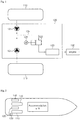
- Fig. 1 is a diagram of a fuel gas supply system of a ship according to one embodiment of the present invention
- Fig. 2 is a plan view of the fuel gas supply system of a ship according to the embodiment of the present invention
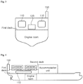
- Fig. 3 is a sectional view of arrangement of the fuel gas supply system of a ship according to the embodiment of the present invention
- Fig. 4 is a side view of the fuel gas supply system of a ship according to the embodiment of the present invention
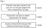
- Fig. 5 is a flow diagram of a fuel gas supply method of a ship according to one embodiment of the present invention.
- a fuel gas supply system of a ship includes a fuel gas tank 110, a fuel gas supply (FGS) room 120, an engine 130, a bunkering manifold 140 and a vent riser 150, and the engine 130 is placed in an engine room.
- FGS fuel gas supply
- the fuel gas tank 110 stores fuel gas to be supplied to the engine 130, and machinery in the FGS room 120 pressurizes the fuel gas in fuel gas tank 110 to supply the pressurized fuel gas to the engine 130.
- the engine 130 is a gas-powered engine that generates drive force using the fuel gas supplied from the fuel gas tank 110.
- the engine 130 may be an MEGI engine or a heterogeneous fuel engine.
- the engine 130 When the engine 130 is a heterogeneous fuel engine, the engine 130 may selectively receive LNG or oil. However, in order to prevent deterioration in efficiency of the engine 130, the fuel gas supply system may prevent supply of a mixture of LNG and oil.
- the engine 130 will be illustrated as an engine for driving the propeller in this embodiment, it should be understood that the engine 130 may be an engine for generation of electric power or other types of power. That is, the engine 130 according to this embodiment is not limited to a certain kind of engine.
- the engine 130 may be an internal combustion engine that generates drive force through combustion of LNG.
- the engine 130 is disposed in the engine room.
- the engine room is placed at the stern of the ship.
- the fuel gas tank 110 stores fuel gas to be supplied to the engine 130.
- the fuel gas tank 110 generally stores the fuel gas in a liquid state.
- natural gas is liquefied at a cryogenic temperature of about -163°C under normal pressure
- the natural gas is likely to evaporate at a temperature even slightly higher than -163°C under normal pressure.
- the fuel gas tank 110 is in an insulated state, since external heat is continuously supplied to the natural gas, the natural gas is continuously evaporated within the fuel gas tank to generate boil-off gas (BOG) within the fuel gas tank 110, whereby an internal pressure of the fuel gas tank 110 can be increased.
- the fuel gas tank 110 may take the form of a pressure tank.
- BOG may be used as fuel in the ship or may be liquefied and transferred again to the fuel gas tank 110.
- the fuel gas tank 110 is placed above the engine room. This arrangement enables efficient use of a space in the ship while minimizing a length of a fuel gas supply line 124 extending from the fuel gas tank 110 to the engine room. That is, the fuel gas tank 110 is placed behind an accommodation unit. As shown in Figs. 3 and 4 , a first deck may be disposed above the engine room, and the fuel gas tank 110 may be disposed on the first deck. Here, the first deck may be a main deck.
- a cargo hold for loading containers is generally placed in front of the engine room.
- the container since the containers are loaded from above, the container cannot be loaded below the fuel gas tank 110.
- the fuel gas tank 110 is placed above the cargo hold instead of the engine room, the containers cannot be loaded on the cargo hold below the fuel gas tank 110, so that a cargo amount to be loaded on the ship is decreased, thereby causing loss.
- the arrangement of the fuel gas tank 110 disposed above the engine room enables efficient use of the space in the ship.
- the fuel gas tank 110 may be disposed in a longitudinal direction of the ship.
- Sloshing refers to relative movement between a fluid and a container containing the fluid.
- the sloshing phenomenon is generated within a transport container, generating impact, by which the transport container can be damaged. That is, fuel gas rolls within the fuel gas tank 110 due to rolling movement of the ship, whereby the fuel gas tank 110 can be damaged.
- the arrangement of the fuel gas tank 110 disposed in the longitudinal direction of the ship reduces force applied to the fuel gas tank 110 by rolling of the fuel gas due to rolling of the ship, thereby preventing damage to the fuel gas tank 110.
- a second deck may be additionally disposed above the fuel gas tank 110 to load a container thereon.
- two fuel gas tanks 110 are disposed on the ship.
- the fuel gas supply system according to the invention may include a single fuel gas tank 110 or a plurality of fuel gas tanks 110 for failsafe redundancy.
- the FGS room 120 includes the fuel gas supply line 124, a primary pump 121, a secondary pump 122, and a heater 123.
- the fuel gas supply line 124 is a pipe for transferring the fuel gas from the fuel gas tank 110 to the engine 130. As shown in Fig. 1 , the fuel gas supply line 124 is provided with the primary pump 121, the secondary pump 122 and the heater 123 to supply the fuel gas to the engine 130 after changing the pressure and temperature of the fuel gas to a desired pressure and temperature for the engine 130.
- the fuel gas supply line 124 may be provided with a fuel supply valve to adjust a supply amount of fuel gas through adjustment of a degree of opening the fuel supply valve.
- the primary pump 121 transfers the fuel gas stored in the fuel gas tank 110 to the fuel gas supply line 124 after pressurizing the fuel gas to several MPa (dozen bar). As shown in Fig. 1 , a single primary pump 121 is connected to each of the fuel gas tanks 110 and transfers the fuel gas stored in the corresponding fuel gas tank 110 to the fuel gas supply line 124. The fuel gas supply lines 124 are combined before the secondary pump 122.
- Fig. 1 two primary pumps 121, a single secondary pump 122 and a single heater 123 are shown. However, it should be understood that the fuel gas supply system according to the present invention may include certain numbers of primary pumps 121, secondary pumps 122 and heaters 123.
- the primary pump 121 is illustrated as being disposed outside the fuel gas tank 110 in Fig. 1 , the primary pump 121 may be disposed inside the fuel gas tank 110.
- the secondary pump 122 is a high pressure pump and pressurizes the fuel gas to a pressure required for the engine 130, for example, to a pressure of 20 to 40 MPa (200 to 400 bar).
- the secondary pump 122 may be driven by a motor 125.
- the heater 123 supplies the fuel gas to the engine after heating the fuel gas pressurized by the secondary pump 122 to a temperature required for the engine 130.
- the FGS room 120 is disposed above the engine room. This arrangement enables efficient use of the space in the ship and minimizes the length of the fuel gas supply line 124 extending from the FGS room 120 to the engine room. As shown in Figs. 3 and 4 , the first deck is disposed above the engine room, and the FGS room may be disposed above the first deck.
- the FGS room 120 may be placed near the fuel gas tank 110.
- the arrangement can minimize the length of the fuel gas supply line 124 connecting the fuel gas tank 110 and the FGS room 120.
- the FGS room 120 may be disposed between the two fuel gas tanks 110. This structure can minimize the length of the fuel gas supply line 124 connecting the fuel gas tank 110 to the FGS room 120.
- the bunkering manifold 140 is an apparatus for receiving the fuel gas. That is, the ship receives the fuel gas supplied from an external reservoir, for example, an LNG bunkering ship, and stores the fuel gas in the fuel gas tank 110.
- the device for receiving the fuel gas supplied from the external reservoir is the bunkering manifold 140.
- the bunkering manifold 140 is connected to the fuel gas tank 110 and a fuel gas transfer line, and supplies the fuel gas to the fuel gas tank 110 through the fuel gas transfer line.
- the bunkering manifold 140 is disposed at one side of the stern in order to facilitate supply of the fuel gas.
- the bunkering manifold 140 may be disposed at one side of the fuel gas tank 110 to secure convenient transfer of the fuel gas to the fuel gas tank 110.
- the vent riser 150 is a discharge port through which BOG of the fuel gas tank 110 and the FGS room 120 is discharged in an emergency.
- the vent riser 150 is connected to the fuel gas tank 110 and the FGS room 140 by a BOG transfer line.
- BOG may be used as fuel within the ship or may be liquefied and transferred again to the fuel gas tank 110.
- inner pressure of the fuel gas tank 110 can be increased.
- the vent riser 150 discharges BOG of the fuel gas tank 110.
- the vent riser 150 may also discharge BOG of the FGS room 140 in an emergency.
- the vent riser 150 is disposed at the stern of the ship to prevent the fuel gas from approaching an accommodation unit or non-hazardous cargo such as a cooling container. Further, the bunkering manifold 140 and the vent riser 150 are respectively disposed at opposite sides of the ship, thereby reducing explosion due to the fuel gas.
- the bunkering manifold 140 may be disposed at the portside of the ship and the vent riser 150 may be disposed at the starboard of the ship.
- the bunkering manifold 140 may be disposed on the starboard of the ship and the vent riser 150 may be disposed on the portside of the ship.
- the arrangement wherein the bunkering manifold 140 and the vent riser 150 are disposed at opposite sides reduces a risk of explosion by the fuel gas.
- Fig. 5 is a flow diagram of a fuel gas supply method of a ship according to one embodiment of the present invention.
- a primary pump 121 pressurizes fuel gas stored in a fuel gas tank 110 and transfers the fuel gas to a fuel gas supply line 124 (S510).
- a secondary pump 122 pressurizes the fuel gas to a pressure required for an engine 130, for example, to a pressure of 20 to 40 MPa (200 to 400 bar).
- a heater 123 supplies the fuel gas to the engine after heating the fuel gas pressurized by the secondary pump 122 to a temperature required for the engine 130 (S530).
- the fuel gas tank 110 is disposed above an engine room to enable efficient use of a space in the ship while minimizing a length of the fuel gas supply line 124 extending from the fuel gas tank 110 to the engine room. Further, as shown in Fig. 2 , the fuel gas tank 110 may be disposed in a longitudinal direction of the ship to minimize a sloshing phenomenon. Further, as shown in Fig. 4 , a second deck may be additionally disposed above the fuel gas tank 110 to allow a container to be loaded thereon.
- a FGS room 120 including a primary pump 121, a secondary pump 122 and a heater 123 is disposed above the engine room to enable efficient use of the space in the ship while minimizing the length of the fuel gas supply line 124 extending from the FGS room 120 to the engine room. Further, the FGS room 120 may be disposed near the fuel gas tank 110 to minimize the length of the fuel gas supply line 124 extending from the fuel gas tank 110 to the FGS room 120.
Landscapes
- Engineering & Computer Science (AREA)
- Chemical & Material Sciences (AREA)
- Combustion & Propulsion (AREA)
- Mechanical Engineering (AREA)
- Ocean & Marine Engineering (AREA)
- Chemical Kinetics & Catalysis (AREA)
- General Chemical & Material Sciences (AREA)
- Oil, Petroleum & Natural Gas (AREA)
- General Engineering & Computer Science (AREA)
- Environmental & Geological Engineering (AREA)
- Filling Or Discharging Of Gas Storage Vessels (AREA)
- Output Control And Ontrol Of Special Type Engine (AREA)
Claims (13)
- Brenngaszuführungssystem für ein Schiff, umfassend:ein Motor (130), der Antriebskraft unter Verwendung des Brenngases erzeugt,ein Brenngastank (110), der Brenngas unterbringt, das dem Motor zuzuführen ist, undein Bunkerverteilrohr (140), das das Brenngas, das von außerhalb des Schiffs zugeführt wird, empfängt und das Brenngas dem Brenngastank (110) zuführt, undeine Abzugsleitung (150), die Abdampfgas (BOG) des Brenngastanks bei einem Gefahrenfall ablässt,wobei der Motor in einem Motorraum angeordnet ist, welcher sich am Heck des Schiffs befindet,das Bunkerverteilrohr an einer Seite des Hecks des Schiffs angeordnet ist,die Abzugsleitung am Heck des Schiffs angeordnet ist, und dadurch gekennzeichnet, dass das Bunkerverteilrohr und die Abzugsleitung jeweils an gegenüberliegenden Seiten des Schiffs angeordnet sind.
- Brenngaszuführsystem eines Schiffs nach Anspruch 1, wobei der Brenngastank (110) in einer Längsrichtung des Schiffs angeordnet ist.
- Brenngaszuführsystem eines Schiffs nach Anspruch 1 oder 2, wobei das Schiff ein Containerschiff ist.
- Brenngaszuführsystem eines Schiffs nach Anspruch 3, wobei der Brenngastank (110) auf einem ersten Deck angeordnet ist und ein zweites Deck über dem Brenngastank angeordnet ist, damit ein Container auf das zweite Deck geladen werden kann.
- Brenngaszuführsystem eines Schiffs nach einem der Ansprüche 1 bis 4, ferner umfassend:
eine Brenngaszuführ(FGS)-Kammer, die eine Anlage enthält zum Zuführen des Brenngases zum Motor, nachdem das Brenngas, das in dem Brenngastank (110) untergebracht ist, mit Druck beaufschlagt wurde. - Brenngaszuführsystem eines Schiffs nach Anspruch 5, wobei die Brenngaszuführkammer umfasst:eine Brenngaszuführleitung (124), die das Brenngas, das im Brenngastank (110) untergebracht ist, zu dem Motor (130) weiterleitet,eine Hochdruckpumpe (122), die das Brenngas, das im Brenngastank (110) untergebracht ist, mit Druck beaufschlagt, undeine Heizeinrichtung (123), die das mit Druck beaufschlagte Brenngas erhitzt.
- Brenngaszuführsystem eines Schiffs nach Anspruch 5, wobei die Brenngaszuführkammer über dem Maschinenraum angeordnet ist.
- Brenngaszuführsystem eines Schiffs nach einem der Ansprüche 1 bis 4, wobei der Brenngastank über dem Maschinenraum angeordnet ist.
- Brenngaszuführsystem eines Schiffs nach einem der Ansprüche 1 bis 4, wobei das Bunkerverteilrohr an einer Seite des Brenngastanks angeordnet ist.
- Brenngaszuführsystem eines Schiffs nach einem der Ansprüche 1 bis 4, wobei das Bunkerverteilrohr Brenngas aufnimmt, das von einem LNG-Bunkerschiff geliefert wird.
- Brenngaszuführsystem eines Schiffs nach Anspruch 5, wobei die Abzugsleitung Abdampfgas aus der Brenngaszuführkammer ablässt.
- Brenngaszuführsystem eines Schiffs nach Anspruch 5, wobei die Brenngaszuführkammer an einer Seite des Brenngastanks angeordnet ist.
- Brenngaszuführsystem eines Schiffs nach einem der Ansprüche 1 bis 4, umfassend:zwei Brenngastanks,wobei die Brenngaszuführkammer zwischen den beiden Brenngastanks angeordnet ist.
Applications Claiming Priority (4)
| Application Number | Priority Date | Filing Date | Title |
|---|---|---|---|
| KR1020140001885A KR20150081912A (ko) | 2014-01-07 | 2014-01-07 | 선박의 연료 가스 공급 장치 및 방법 |
| KR1020140001884A KR20150081911A (ko) | 2014-01-07 | 2014-01-07 | 선박의 연료 가스 공급 장치 및 방법 |
| KR1020140001883A KR101654203B1 (ko) | 2014-01-07 | 2014-01-07 | 선박의 연료 가스 공급 장치 |
| PCT/KR2014/010624 WO2015105267A1 (ko) | 2014-01-07 | 2014-11-06 | 선박의 연료 가스 공급 장치 및 방법 |
Publications (3)
| Publication Number | Publication Date |
|---|---|
| EP3095685A1 EP3095685A1 (de) | 2016-11-23 |
| EP3095685A4 EP3095685A4 (de) | 2017-06-14 |
| EP3095685B1 true EP3095685B1 (de) | 2018-10-17 |
Family
ID=53524068
Family Applications (1)
| Application Number | Title | Priority Date | Filing Date |
|---|---|---|---|
| EP14835468.1A Active EP3095685B1 (de) | 2014-01-07 | 2014-11-06 | Vorrichtung und verfahren zur zufuhr von brennstoffgas in ein schiff |
Country Status (9)
| Country | Link |
|---|---|
| US (1) | US9738368B2 (de) |
| EP (1) | EP3095685B1 (de) |
| JP (1) | JP6074066B2 (de) |
| CN (1) | CN104903186B (de) |
| DK (1) | DK3095685T3 (de) |
| RU (1) | RU2607893C2 (de) |
| SA (1) | SA515360144B1 (de) |
| SG (1) | SG11201501548WA (de) |
| WO (1) | WO2015105267A1 (de) |
Families Citing this family (10)
| Publication number | Priority date | Publication date | Assignee | Title |
|---|---|---|---|---|
| EP3095685B1 (de) * | 2014-01-07 | 2018-10-17 | Daewoo Shipbuilding & Marine Engineering Co., Ltd. | Vorrichtung und verfahren zur zufuhr von brennstoffgas in ein schiff |
| WO2017074261A1 (en) * | 2015-10-26 | 2017-05-04 | Keppel Offshore & Marine Technology Centre Pte Ltd | An arrangement of cyrogenic containers for lng or cng on a deck of a tugboat |
| JP6877248B2 (ja) * | 2017-06-06 | 2021-05-26 | 川崎重工業株式会社 | ガス放出システム |
| CN109421910A (zh) * | 2017-09-05 | 2019-03-05 | 中集集团集装箱控股有限公司 | 集装箱运输船及其供气系统 |
| JP6426254B1 (ja) * | 2017-11-15 | 2018-11-21 | 株式会社新来島どっく | ガス燃料船のバンカーステーションの舷側ウォーターカーテン水圧を利用するバンカーステーション換気構造 |
| JP7011713B2 (ja) * | 2017-11-17 | 2022-01-27 | デウ シップビルディング アンド マリン エンジニアリング カンパニー リミテッド | 液化燃料発電及び物流システム、並びにそのシステムを利用した荷役方法 |
| WO2019146087A1 (ja) * | 2018-01-26 | 2019-08-01 | 株式会社大島造船所 | 船舶用のlng燃料モジュールと該lng燃料モジュールを搭載した船舶 |
| CN110356509B (zh) * | 2019-07-18 | 2021-03-19 | 上海外高桥造船有限公司 | 双燃料油船供气系统及油船 |
| JP7645608B2 (ja) * | 2020-01-31 | 2025-03-14 | 三菱造船株式会社 | 船舶 |
| JP2023158761A (ja) * | 2022-04-19 | 2023-10-31 | 三菱造船株式会社 | 船舶 |
Citations (1)
| Publication number | Priority date | Publication date | Assignee | Title |
|---|---|---|---|---|
| KR20110090038A (ko) * | 2010-02-02 | 2011-08-10 | 삼성중공업 주식회사 | 연료가스 공급장치 |
Family Cites Families (20)
| Publication number | Priority date | Publication date | Assignee | Title |
|---|---|---|---|---|
| US5121609A (en) * | 1991-05-17 | 1992-06-16 | Minnesota Valley Engineering | No loss fueling station for liquid natural gas vehicles |
| US5127230A (en) * | 1991-05-17 | 1992-07-07 | Minnesota Valley Engineering, Inc. | LNG delivery system for gas powered vehicles |
| US5329777A (en) * | 1993-06-24 | 1994-07-19 | The Boc Group, Inc. | Cryogenic storage and delivery method and apparatus |
| GB9501169D0 (en) * | 1995-01-20 | 1995-03-08 | British Petroleum Co Plc | Improvements in and relating to ships |
| FI123864B (fi) * | 2006-06-19 | 2013-11-29 | Waertsilae Finland Oy | Vesikulkuneuvo |
| FI122137B (fi) * | 2006-06-27 | 2011-09-15 | Waertsilae Finland Oy | Kaasukäyttöisen laivan polttoainejärjestelmä |
| JP2008126829A (ja) | 2006-11-21 | 2008-06-05 | Chugoku Electric Power Co Inc:The | 船舶 |
| KR101076266B1 (ko) | 2007-07-19 | 2011-10-26 | 대우조선해양 주식회사 | Lng 운반선의 연료용 가스 공급 장치 |
| KR20090098387A (ko) | 2008-03-14 | 2009-09-17 | 대우조선해양 주식회사 | 추진용 청정연료저장탱크를 상갑판에 구비한 선박 |
| KR101187532B1 (ko) * | 2009-03-03 | 2012-10-02 | 에스티엑스조선해양 주식회사 | 재액화 기능을 가지는 전기추진 lng 운반선의 증발가스 처리장치 |
| KR100961867B1 (ko) * | 2009-10-16 | 2010-06-09 | 대우조선해양 주식회사 | 가스연료용 연료탱크를 가지는 부유식 구조물 |
| KR101681703B1 (ko) * | 2009-10-29 | 2016-12-01 | 대우조선해양 주식회사 | 액화연료가스 추진 컨테이너 운반선 |
| FI121876B (fi) * | 2010-04-09 | 2011-05-31 | Waertsilae Finland Oy | Menetelmä LNG:tä polttoaineenaan käyttävän vesialuksen käyttämiseksi ja vastaava vesialus |
| JP6143407B2 (ja) * | 2010-12-07 | 2017-06-07 | 三菱重工業株式会社 | 船舶 |
| CN103314208B (zh) * | 2010-12-27 | 2015-11-25 | 瓦锡兰芬兰有限公司 | 燃料供给系统和操作燃料供给系统的方法 |
| KR101205351B1 (ko) * | 2011-01-21 | 2012-11-28 | 삼성중공업 주식회사 | 연료 공급 선박 |
| KR20120125129A (ko) | 2011-05-04 | 2012-11-14 | 대우조선해양 주식회사 | 고압가스 분사엔진용 연료가스 공급 시스템을 갖는 lng 운반선 |
| KR101551791B1 (ko) * | 2011-05-31 | 2015-09-09 | 대우조선해양 주식회사 | Lng 연료 선박 |
| KR101380644B1 (ko) * | 2011-12-23 | 2014-04-08 | 삼성중공업 주식회사 | 가스연료 추진선박 |
| EP3095685B1 (de) * | 2014-01-07 | 2018-10-17 | Daewoo Shipbuilding & Marine Engineering Co., Ltd. | Vorrichtung und verfahren zur zufuhr von brennstoffgas in ein schiff |
-
2014
- 2014-11-06 EP EP14835468.1A patent/EP3095685B1/de active Active
- 2014-11-06 RU RU2015104988A patent/RU2607893C2/ru active
- 2014-11-06 SG SG11201501548WA patent/SG11201501548WA/en unknown
- 2014-11-06 US US14/421,811 patent/US9738368B2/en active Active
- 2014-11-06 WO PCT/KR2014/010624 patent/WO2015105267A1/ko not_active Ceased
- 2014-11-06 JP JP2015556895A patent/JP6074066B2/ja active Active
- 2014-11-06 CN CN201480002133.0A patent/CN104903186B/zh active Active
- 2014-11-06 DK DK14835468.1T patent/DK3095685T3/en active
-
2015
- 2015-03-15 SA SA515360144A patent/SA515360144B1/ar unknown
Patent Citations (1)
| Publication number | Priority date | Publication date | Assignee | Title |
|---|---|---|---|---|
| KR20110090038A (ko) * | 2010-02-02 | 2011-08-10 | 삼성중공업 주식회사 | 연료가스 공급장치 |
Also Published As
| Publication number | Publication date |
|---|---|
| CN104903186B (zh) | 2017-11-14 |
| US9738368B2 (en) | 2017-08-22 |
| US20160096609A1 (en) | 2016-04-07 |
| EP3095685A1 (de) | 2016-11-23 |
| RU2015104988A (ru) | 2016-08-27 |
| JP2016508916A (ja) | 2016-03-24 |
| SG11201501548WA (en) | 2015-08-28 |
| SA515360144B1 (ar) | 2017-11-21 |
| RU2607893C2 (ru) | 2017-01-11 |
| CN104903186A (zh) | 2015-09-09 |
| JP6074066B2 (ja) | 2017-02-01 |
| EP3095685A4 (de) | 2017-06-14 |
| WO2015105267A1 (ko) | 2015-07-16 |
| DK3095685T3 (en) | 2019-01-07 |
Similar Documents
| Publication | Publication Date | Title |
|---|---|---|
| US9738368B2 (en) | Fuel gas supply system and method of ship | |
| KR102375718B1 (ko) | 가스연료 추진 선박 | |
| JP5383488B2 (ja) | ガス駆動船舶用燃料システム | |
| EP2659120B1 (de) | Kraftstoffzufuhrsystem und verfahren zum betrieb eines kraftstoffzufuhrsystems | |
| KR101577804B1 (ko) | 선박 및 선박의 배치 구조 | |
| KR20120113398A (ko) | 듀얼 연료시스템이 마련된 액화석유가스 운반선 | |
| KR102297873B1 (ko) | 이중연료 엔진을 구비하는 선박의 연료가스 공급시스템 | |
| KR101577805B1 (ko) | 선박 및 선박의 배치 방법 | |
| JP6712570B2 (ja) | 船舶 | |
| KR20150102238A (ko) | 선박 및 선박의 배치 구조 | |
| KR20130021204A (ko) | 전기 추진식 엘엔지 연료급유선 | |
| KR101654203B1 (ko) | 선박의 연료 가스 공급 장치 | |
| KR20150102237A (ko) | 선박 및 선박의 배치 구조 | |
| KR20110041940A (ko) | 이종연료 추진 시스템을 가지는 부유식 구조물 | |
| KR20150102236A (ko) | 선박 및 선박의 배치 구조 | |
| KR20140001569A (ko) | 액화연료가스 추진 선박 | |
| KR102297871B1 (ko) | 이중연료 엔진을 구비하는 선박의 연료가스 공급시스템 | |
| KR102711415B1 (ko) | 가스 처리 시스템 및 이를 포함하는 선박 | |
| KR102711385B1 (ko) | 가스 처리 시스템 및 이를 포함하는 선박 | |
| KR20150081911A (ko) | 선박의 연료 가스 공급 장치 및 방법 | |
| KR102176541B1 (ko) | 벤트 마스터 유닛 및 이를 구비한 액화천연가스 운반선 | |
| KR20150081912A (ko) | 선박의 연료 가스 공급 장치 및 방법 | |
| KR102711382B1 (ko) | 가스 처리 시스템 및 이를 포함하는 선박 | |
| KR102711410B1 (ko) | 가스 처리 시스템 및 이를 포함하는 선박 | |
| KR102261776B1 (ko) | 원유 운반선 |
Legal Events
| Date | Code | Title | Description |
|---|---|---|---|
| PUAI | Public reference made under article 153(3) epc to a published international application that has entered the european phase |
Free format text: ORIGINAL CODE: 0009012 |
|
| 17P | Request for examination filed |
Effective date: 20150213 |
|
| AK | Designated contracting states |
Kind code of ref document: A1 Designated state(s): AL AT BE BG CH CY CZ DE DK EE ES FI FR GB GR HR HU IE IS IT LI LT LU LV MC MK MT NL NO PL PT RO RS SE SI SK SM TR |
|
| AX | Request for extension of the european patent |
Extension state: BA ME |
|
| DAX | Request for extension of the european patent (deleted) | ||
| A4 | Supplementary search report drawn up and despatched |
Effective date: 20170516 |
|
| RIC1 | Information provided on ipc code assigned before grant |
Ipc: F02M 21/02 20060101ALI20170510BHEP Ipc: B63B 11/04 20060101AFI20170510BHEP Ipc: F16K 15/00 20060101ALI20170510BHEP Ipc: B63H 21/38 20060101ALI20170510BHEP |
|
| RIC1 | Information provided on ipc code assigned before grant |
Ipc: F16K 15/00 20060101ALI20180119BHEP Ipc: B63B 11/04 20060101AFI20180119BHEP Ipc: B63H 21/38 20060101ALI20180119BHEP Ipc: F02M 21/02 20060101ALI20180119BHEP |
|
| GRAP | Despatch of communication of intention to grant a patent |
Free format text: ORIGINAL CODE: EPIDOSNIGR1 |
|
| INTG | Intention to grant announced |
Effective date: 20180503 |
|
| GRAS | Grant fee paid |
Free format text: ORIGINAL CODE: EPIDOSNIGR3 |
|
| GRAA | (expected) grant |
Free format text: ORIGINAL CODE: 0009210 |
|
| AK | Designated contracting states |
Kind code of ref document: B1 Designated state(s): AL AT BE BG CH CY CZ DE DK EE ES FI FR GB GR HR HU IE IS IT LI LT LU LV MC MK MT NL NO PL PT RO RS SE SI SK SM TR |
|
| REG | Reference to a national code |
Ref country code: GB Ref legal event code: FG4D |
|
| REG | Reference to a national code |
Ref country code: CH Ref legal event code: EP |
|
| REG | Reference to a national code |
Ref country code: IE Ref legal event code: FG4D |
|
| REG | Reference to a national code |
Ref country code: DE Ref legal event code: R096 Ref document number: 602014034399 Country of ref document: DE Ref country code: AT Ref legal event code: REF Ref document number: 1053673 Country of ref document: AT Kind code of ref document: T Effective date: 20181115 |
|
| REG | Reference to a national code |
Ref country code: NL Ref legal event code: FP |
|
| REG | Reference to a national code |
Ref country code: DK Ref legal event code: T3 Effective date: 20190104 |
|
| REG | Reference to a national code |
Ref country code: NO Ref legal event code: T2 Effective date: 20181017 |
|
| REG | Reference to a national code |
Ref country code: LT Ref legal event code: MG4D |
|
| REG | Reference to a national code |
Ref country code: AT Ref legal event code: MK05 Ref document number: 1053673 Country of ref document: AT Kind code of ref document: T Effective date: 20181017 |
|
| PG25 | Lapsed in a contracting state [announced via postgrant information from national office to epo] |
Ref country code: IS Free format text: LAPSE BECAUSE OF FAILURE TO SUBMIT A TRANSLATION OF THE DESCRIPTION OR TO PAY THE FEE WITHIN THE PRESCRIBED TIME-LIMIT Effective date: 20190217 Ref country code: BG Free format text: LAPSE BECAUSE OF FAILURE TO SUBMIT A TRANSLATION OF THE DESCRIPTION OR TO PAY THE FEE WITHIN THE PRESCRIBED TIME-LIMIT Effective date: 20190117 Ref country code: LT Free format text: LAPSE BECAUSE OF FAILURE TO SUBMIT A TRANSLATION OF THE DESCRIPTION OR TO PAY THE FEE WITHIN THE PRESCRIBED TIME-LIMIT Effective date: 20181017 Ref country code: ES Free format text: LAPSE BECAUSE OF FAILURE TO SUBMIT A TRANSLATION OF THE DESCRIPTION OR TO PAY THE FEE WITHIN THE PRESCRIBED TIME-LIMIT Effective date: 20181017 Ref country code: LV Free format text: LAPSE BECAUSE OF FAILURE TO SUBMIT A TRANSLATION OF THE DESCRIPTION OR TO PAY THE FEE WITHIN THE PRESCRIBED TIME-LIMIT Effective date: 20181017 Ref country code: PL Free format text: LAPSE BECAUSE OF FAILURE TO SUBMIT A TRANSLATION OF THE DESCRIPTION OR TO PAY THE FEE WITHIN THE PRESCRIBED TIME-LIMIT Effective date: 20181017 Ref country code: HR Free format text: LAPSE BECAUSE OF FAILURE TO SUBMIT A TRANSLATION OF THE DESCRIPTION OR TO PAY THE FEE WITHIN THE PRESCRIBED TIME-LIMIT Effective date: 20181017 Ref country code: AT Free format text: LAPSE BECAUSE OF FAILURE TO SUBMIT A TRANSLATION OF THE DESCRIPTION OR TO PAY THE FEE WITHIN THE PRESCRIBED TIME-LIMIT Effective date: 20181017 Ref country code: FI Free format text: LAPSE BECAUSE OF FAILURE TO SUBMIT A TRANSLATION OF THE DESCRIPTION OR TO PAY THE FEE WITHIN THE PRESCRIBED TIME-LIMIT Effective date: 20181017 |
|
| PG25 | Lapsed in a contracting state [announced via postgrant information from national office to epo] |
Ref country code: AL Free format text: LAPSE BECAUSE OF FAILURE TO SUBMIT A TRANSLATION OF THE DESCRIPTION OR TO PAY THE FEE WITHIN THE PRESCRIBED TIME-LIMIT Effective date: 20181017 Ref country code: RS Free format text: LAPSE BECAUSE OF FAILURE TO SUBMIT A TRANSLATION OF THE DESCRIPTION OR TO PAY THE FEE WITHIN THE PRESCRIBED TIME-LIMIT Effective date: 20181017 Ref country code: SE Free format text: LAPSE BECAUSE OF FAILURE TO SUBMIT A TRANSLATION OF THE DESCRIPTION OR TO PAY THE FEE WITHIN THE PRESCRIBED TIME-LIMIT Effective date: 20181017 Ref country code: GR Free format text: LAPSE BECAUSE OF FAILURE TO SUBMIT A TRANSLATION OF THE DESCRIPTION OR TO PAY THE FEE WITHIN THE PRESCRIBED TIME-LIMIT Effective date: 20190118 Ref country code: PT Free format text: LAPSE BECAUSE OF FAILURE TO SUBMIT A TRANSLATION OF THE DESCRIPTION OR TO PAY THE FEE WITHIN THE PRESCRIBED TIME-LIMIT Effective date: 20190217 |
|
| REG | Reference to a national code |
Ref country code: CH Ref legal event code: PL |
|
| REG | Reference to a national code |
Ref country code: DE Ref legal event code: R097 Ref document number: 602014034399 Country of ref document: DE |
|
| PG25 | Lapsed in a contracting state [announced via postgrant information from national office to epo] |
Ref country code: CZ Free format text: LAPSE BECAUSE OF FAILURE TO SUBMIT A TRANSLATION OF THE DESCRIPTION OR TO PAY THE FEE WITHIN THE PRESCRIBED TIME-LIMIT Effective date: 20181017 Ref country code: IT Free format text: LAPSE BECAUSE OF FAILURE TO SUBMIT A TRANSLATION OF THE DESCRIPTION OR TO PAY THE FEE WITHIN THE PRESCRIBED TIME-LIMIT Effective date: 20181017 Ref country code: LU Free format text: LAPSE BECAUSE OF NON-PAYMENT OF DUE FEES Effective date: 20181106 |
|
| REG | Reference to a national code |
Ref country code: IE Ref legal event code: MM4A |
|
| PLBE | No opposition filed within time limit |
Free format text: ORIGINAL CODE: 0009261 |
|
| STAA | Information on the status of an ep patent application or granted ep patent |
Free format text: STATUS: NO OPPOSITION FILED WITHIN TIME LIMIT |
|
| PG25 | Lapsed in a contracting state [announced via postgrant information from national office to epo] |
Ref country code: EE Free format text: LAPSE BECAUSE OF FAILURE TO SUBMIT A TRANSLATION OF THE DESCRIPTION OR TO PAY THE FEE WITHIN THE PRESCRIBED TIME-LIMIT Effective date: 20181017 Ref country code: SM Free format text: LAPSE BECAUSE OF FAILURE TO SUBMIT A TRANSLATION OF THE DESCRIPTION OR TO PAY THE FEE WITHIN THE PRESCRIBED TIME-LIMIT Effective date: 20181017 Ref country code: CH Free format text: LAPSE BECAUSE OF NON-PAYMENT OF DUE FEES Effective date: 20181130 Ref country code: LI Free format text: LAPSE BECAUSE OF NON-PAYMENT OF DUE FEES Effective date: 20181130 Ref country code: RO Free format text: LAPSE BECAUSE OF FAILURE TO SUBMIT A TRANSLATION OF THE DESCRIPTION OR TO PAY THE FEE WITHIN THE PRESCRIBED TIME-LIMIT Effective date: 20181017 Ref country code: MC Free format text: LAPSE BECAUSE OF FAILURE TO SUBMIT A TRANSLATION OF THE DESCRIPTION OR TO PAY THE FEE WITHIN THE PRESCRIBED TIME-LIMIT Effective date: 20181017 Ref country code: SK Free format text: LAPSE BECAUSE OF FAILURE TO SUBMIT A TRANSLATION OF THE DESCRIPTION OR TO PAY THE FEE WITHIN THE PRESCRIBED TIME-LIMIT Effective date: 20181017 |
|
| 26N | No opposition filed |
Effective date: 20190718 |
|
| GBPC | Gb: european patent ceased through non-payment of renewal fee |
Effective date: 20190117 |
|
| PG25 | Lapsed in a contracting state [announced via postgrant information from national office to epo] |
Ref country code: FR Free format text: LAPSE BECAUSE OF NON-PAYMENT OF DUE FEES Effective date: 20181217 Ref country code: IE Free format text: LAPSE BECAUSE OF NON-PAYMENT OF DUE FEES Effective date: 20181106 Ref country code: SI Free format text: LAPSE BECAUSE OF FAILURE TO SUBMIT A TRANSLATION OF THE DESCRIPTION OR TO PAY THE FEE WITHIN THE PRESCRIBED TIME-LIMIT Effective date: 20181017 |
|
| PG25 | Lapsed in a contracting state [announced via postgrant information from national office to epo] |
Ref country code: GB Free format text: LAPSE BECAUSE OF NON-PAYMENT OF DUE FEES Effective date: 20190117 |
|
| PG25 | Lapsed in a contracting state [announced via postgrant information from national office to epo] |
Ref country code: MT Free format text: LAPSE BECAUSE OF NON-PAYMENT OF DUE FEES Effective date: 20181106 |
|
| PG25 | Lapsed in a contracting state [announced via postgrant information from national office to epo] |
Ref country code: TR Free format text: LAPSE BECAUSE OF FAILURE TO SUBMIT A TRANSLATION OF THE DESCRIPTION OR TO PAY THE FEE WITHIN THE PRESCRIBED TIME-LIMIT Effective date: 20181017 |
|
| PG25 | Lapsed in a contracting state [announced via postgrant information from national office to epo] |
Ref country code: HU Free format text: LAPSE BECAUSE OF FAILURE TO SUBMIT A TRANSLATION OF THE DESCRIPTION OR TO PAY THE FEE WITHIN THE PRESCRIBED TIME-LIMIT; INVALID AB INITIO Effective date: 20141106 Ref country code: CY Free format text: LAPSE BECAUSE OF FAILURE TO SUBMIT A TRANSLATION OF THE DESCRIPTION OR TO PAY THE FEE WITHIN THE PRESCRIBED TIME-LIMIT Effective date: 20181017 Ref country code: MK Free format text: LAPSE BECAUSE OF NON-PAYMENT OF DUE FEES Effective date: 20181017 |
|
| REG | Reference to a national code |
Ref country code: DE Ref legal event code: R082 Ref document number: 602014034399 Country of ref document: DE Representative=s name: CBDL PATENTANWAELTE GBR, DE Ref country code: DE Ref legal event code: R082 Ref document number: 602014034399 Country of ref document: DE Representative=s name: CBDL PATENTANWAELTE EGBR, DE |
|
| P01 | Opt-out of the competence of the unified patent court (upc) registered |
Effective date: 20230526 |
|
| REG | Reference to a national code |
Ref country code: NL Ref legal event code: HC Owner name: HANWHA OCEAN CO., LTD.; KR Free format text: DETAILS ASSIGNMENT: CHANGE OF OWNER(S), CHANGE OF OWNER(S) NAME; FORMER OWNER NAME: DAEWOO SHIPBUILDING & MARINE ENGINEERING CO., LTD. Effective date: 20240119 |
|
| REG | Reference to a national code |
Ref country code: DE Ref legal event code: R081 Ref document number: 602014034399 Country of ref document: DE Owner name: HANWHA OCEAN CO., LTD., GEOJE-SI, KR Free format text: FORMER OWNER: DAEWOO SHIPBUILDING & MARINE ENGINEERING CO., LTD., SEOUL, KR |
|
| REG | Reference to a national code |
Ref country code: BE Ref legal event code: HC Owner name: HANWHA OCEAN CO., LTD.; KR Free format text: DETAILS ASSIGNMENT: CHANGE OF OWNER(S), CHANGE OF OWNER(S) NAME; FORMER OWNER NAME: DAEWOO SHIPBUILDING & MARINE ENGINEERING CO., LTD. Effective date: 20240201 |
|
| PGFP | Annual fee paid to national office [announced via postgrant information from national office to epo] |
Ref country code: NL Payment date: 20251020 Year of fee payment: 12 |
|
| PGFP | Annual fee paid to national office [announced via postgrant information from national office to epo] |
Ref country code: DE Payment date: 20251020 Year of fee payment: 12 |
|
| PGFP | Annual fee paid to national office [announced via postgrant information from national office to epo] |
Ref country code: NO Payment date: 20251024 Year of fee payment: 12 |
|
| PGFP | Annual fee paid to national office [announced via postgrant information from national office to epo] |
Ref country code: DK Payment date: 20251022 Year of fee payment: 12 |
|
| PGFP | Annual fee paid to national office [announced via postgrant information from national office to epo] |
Ref country code: BE Payment date: 20251020 Year of fee payment: 12 |