EP3095745B1 - Balles de levage de tête d'injecteur - Google Patents
Balles de levage de tête d'injecteur Download PDFInfo
- Publication number
- EP3095745B1 EP3095745B1 EP16170911.8A EP16170911A EP3095745B1 EP 3095745 B1 EP3095745 B1 EP 3095745B1 EP 16170911 A EP16170911 A EP 16170911A EP 3095745 B1 EP3095745 B1 EP 3095745B1
- Authority
- EP
- European Patent Office
- Prior art keywords
- injector head
- arm
- cylinder
- lifting
- coiled tubing
- Prior art date
- Legal status (The legal status is an assumption and is not a legal conclusion. Google has not performed a legal analysis and makes no representation as to the accuracy of the status listed.)
- Active
Links
Images



Classifications
-
- B—PERFORMING OPERATIONS; TRANSPORTING
- B66—HOISTING; LIFTING; HAULING
- B66C—CRANES; LOAD-ENGAGING ELEMENTS OR DEVICES FOR CRANES, CAPSTANS, WINCHES, OR TACKLES
- B66C1/00—Load-engaging elements or devices attached to lifting or lowering gear of cranes or adapted for connection therewith for transmitting lifting forces to articles or groups of articles
- B66C1/10—Load-engaging elements or devices attached to lifting or lowering gear of cranes or adapted for connection therewith for transmitting lifting forces to articles or groups of articles by mechanical means
-
- E—FIXED CONSTRUCTIONS
- E21—EARTH OR ROCK DRILLING; MINING
- E21B—EARTH OR ROCK DRILLING; OBTAINING OIL, GAS, WATER, SOLUBLE OR MELTABLE MATERIALS OR A SLURRY OF MINERALS FROM WELLS
- E21B19/00—Handling rods, casings, tubes or the like outside the borehole, e.g. in the derrick; Apparatus for feeding the rods or cables
-
- E—FIXED CONSTRUCTIONS
- E21—EARTH OR ROCK DRILLING; MINING
- E21B—EARTH OR ROCK DRILLING; OBTAINING OIL, GAS, WATER, SOLUBLE OR MELTABLE MATERIALS OR A SLURRY OF MINERALS FROM WELLS
- E21B41/00—Equipment or details not covered by groups E21B15/00 - E21B40/00
Definitions
- Embodiments disclosed herein relate to a coiled tubing unit, more particularly, a lifting bale used to position injector heads in operation and during rig-up and rig-down operations.
- the main engine of a coiled tubing unit is the injector head.
- This component contains the mechanism to push and pull the coiled tubing in and out of the well.
- the injector head is installed on the wellhead. The injector head should be at the correct angle relative to the wellhead to be installed correctly and provide proper entry of the coiled tubing into the wellhead.
- embodiments disclosed herein relate to a lifting bale configured to be mounted on top of an injector head for handling the injector head, the lifting bale including a lifting arm attached to the injector head, an articulated member attached between the injector head and the lifting arm, the articulated member having a knee joint, and a cylinder, having an extendable and retractable arm, attached between the injector head and the knee joint.
- the cylinder arm is configured to be moved to raise the lifting arm, and is further configured to be extended and retracted to provide load balancing of the injector head.
- embodiments disclosed herein relate to a method of handling an injector head, comprising pivotally attaching a lifting arm to the injector head, attaching an articulated member having a knee joint between the lifting arm and the injector head, attaching a cylinder having an arm between the injector head and the knee joint, manipulating the cylinder cable to a distal end of the raised lifting arm and positioning the injector head over a wellbore, and extending or retracting the cylinder arm to balance the injector head.
- a coiled tubing unit including an injector head, a gooseneck mounted on top of the injector head, a lifting bale mounted on top of the injector head, the lifting bale including a lifting arm attached to the injector head, an articulated member attached between the injector head and the lifting arm, the articulated member having a knee joint, and a cylinder having an arm attached between the injector head and the knee joint, wherein the cylinder arm is retracted and extended to balance the injector head.
- FR 1273476A discloses a lifting bale having a lifting arm with an articulated member that is useful for understanding the invention.
- the lifting bale is a mechanism configured to provide load balancing of an injector head during handling operations.
- the injector head lifting bale may be mounted on top of the injector head of a coiled tubing unit.
- the coiled tubing unit may include a complete set of equipment necessary to perform standard continuous-length tubing operations in the field.
- the coiled tubing unit may comprise a reel for storage and transport of coiled tubing, an injector head to provide surface drive force to run and retrieve coiled tubing, a control cabin from which an equipment operator may monitor and control the coiled tubing, and a power pack to generate hydraulic and pneumatic power required to operate the coiled tubing unit.
- the coiled tubing units may further comprise other equipment for continuous-length or coiled tubing operations in the field.
- the coiled tubing unit may comprise onshore coiled tubing units such as a truck mounted coiled tubing unit or larger trailer mounted coiled tubing units.
- the coiled tubing unit may comprise offshore coiled tubing units such as those mounted on a lift boat, barge, offshore platform or any other offshore structure.
- the lifting bale is comprised of various arms secured with pins, hydraulic cylinders that can be manipulated for leveling the injector head, and an arm for connecting the lifting bale to a crane.
- Figure 1 illustrates a general layout of a coiled tubing unit, and particularly, the lifting bale 100 mounted on top of the injector head 90.
- a suspension cable 10 extends downward from a crane (not shown) and attaches to the lifting bale 100.
- Coiled tubing 50 extends from a tubing reel 80, over a gooseneck 95, into an upper end of the injector head 90 and out a lower end into the well (not shown).
- the lifting bale includes a lifting arm that is pivotally attached on a side or anywhere on the injector head.
- the lifting bale includes an articulated member attached between the lifting arm and the injector head.
- the articulated member has a knee joint coupling the first and second arms of the articulated member.
- the knee joint may include a pin inserted through holes in the arms of the articulated member, or any other type of joint.
- the first arm is connected to a pivot point (e.g., pinned or otherwise) on the lifting arm at an end opposite the knee joint.
- the second arm is connected to a pivot point (e.g., pinned or otherwise) on a base structure at an end opposite the knee joint.
- the base structure may be part of the injector head on which the lifting bale is mounted.
- the lifting bale further includes a cylinder having an extendable arm.
- the cylinder may be attached between the base structure and the articulated member.
- the cylinder may be attached at a pivot point (e.g., pinned or otherwise) of the base structure and the knee joint (e.g., pinned or otherwise).
- the cylinder could be attached at a pivot point (not shown) on either the first arm or second arm.
- the cylinder may be a hydraulic cylinder in fluid communication at any pressure with a hydraulic fluid source.
- the cylinder may be pneumatic or electric.
- the cylinder may be mechanical.
- the lifting bale may include one or more extendable cylinders and articulated members on each side of the injector head.
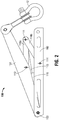
- FIGS 2-4 illustrate an embodiment of a lifting bale 100.
- the lifting bale 100 includes an articulated member 110.
- the articulated member 110 has a knee joint 111 coupling first and second arms (110a, 110b) of the member 110.
- the knee joint 111 may include a pin inserted through holes in the arms of the articulated member 110, or any other type of joint.
- the first arm 110a is connected to a pivot point 112 (e.g., pinned or otherwise) on the lifting arm 104 at an end opposite the knee joint 111.
- the second arm 110b is connected to a pivot point 114 (e.g., pinned or otherwise) on a base structure 102 at an end opposite the knee joint 111.
- the base structure 102 may be part of the injector head (not shown) on which the lifting bale 100 is mounted.
- the lifting bale 100 further includes a cylinder 116 having an extendable arm 115.
- the cylinder 116 may be attached between the base structure 102 and the articulated member 110.
- the cylinder 116 may be attached at a pivot point 103 (e.g., pinned or otherwise) of the base structure 102 and the knee joint 111 (e.g., pinned or otherwise).
- the cylinder 116 could be attached at a pivot point (not shown) on either the first arm 110a or second arm 110b.
- the cylinder 116 may be a hydraulic cylinder in fluid communication at any pressure with a hydraulic fluid source.
- the cylinder 116 may be pneumatic or electric.
- the cylinder 116 may be mechanical.
- the lifting bale 100 may include one or more extendable cylinders and articulated members on each side of the injector head.
- the lifting bale 100 is in the collapsed position (shown in Figure 2 ) where the lifting arm 104 is lowered and almost completely horizontal. During use, the lifting arm 104 is raised in the extended position.
- Methods of using the lifting bale 100 include raising the lifting arm 104 from a collapsed position to an extended position for use, and then lowering the lifting arm 104 from the extended position to the collapsed position for storage or transport. No part of the lifting bale 100 need be unpinned or taken apart to completely collapse the lifting arm 104.
- the cylinder 116 is actuated to retract the cylinder arms 115.
- the cylinder arm 115 because it is attached to the knee joint 111, pulls the articulated member 110, which straightens articulated member 110 and raises an end of the lifting arm 104. Knee joint 111 of the articulated member 110 is pulled until the arms of the articulated member 110 are almost straight.
- a cable 10 (shown in Figure 1 ) extending downward from a crane (not shown) may be attached to a shackle assembly 12 pinned to a distal end of the lifting arm 104. When lifted, the knee joint allows most of the load to pass through the articulated member. The crane positions the injector head over the well.
- the lifting bale 100 may be manipulated to shift the center of gravity as required to maintain vertical alignment.
- various forces may act on the injector head and move it out of vertical alignment with the well.
- the center of gravity of the injector head may shift, directing the bottom of the injector head away from the tubing reel (see arrow "A" indicating direction), directing the tip of the gooseneck downward (see arrow "B"), or directing the top of the injector head towards the reel (see arrow "C").
- the hydraulic cylinder of the lifting bale may be actuated, either to extend or retract the arm 115, to compensate for the various movements.
- the cylinder arm 115 is substantially fully extended.
Landscapes
- Engineering & Computer Science (AREA)
- Life Sciences & Earth Sciences (AREA)
- Geology (AREA)
- Mining & Mineral Resources (AREA)
- Physics & Mathematics (AREA)
- Environmental & Geological Engineering (AREA)
- Fluid Mechanics (AREA)
- General Life Sciences & Earth Sciences (AREA)
- Geochemistry & Mineralogy (AREA)
- Mechanical Engineering (AREA)
- Earth Drilling (AREA)
Claims (6)
- Une unité de tube d'intervention enroulé comprenant :une tête d'injecteur (90) ;un col de cygne (95) monté sur le dessus de la tête d'injecteur (90) ;une anse de levage (100) montée sur le dessus de la tête d'injecteur (90), l'anse de levage (100) comprenant :un bras de levage (104) attaché à la tête d'injecteur (90) ;un élément à charnière (110a, 110b) attaché entre la tête d'injecteur (90) et le bras de levage (104), l'élément à charnière ayant un joint articulé (111) ; etun cylindre (116) ayant un bras (115) attaché entre la tête d'injecteur (90) et le joint articulé (111),dans laquelle le bras de cylindre (115) est rétracté et étendu pour équilibrer la tête d'injecteur (90).
- L'unité de tube d'intervention enroulé de la revendication 1, dans laquelle le cylindre (116) est hydraulique.
- L'unité de tube d'intervention enroulé de la revendication 1, dans laquelle le cylindre (116) est électrique.
- L'unité de tube d'intervention enroulé de la revendication 1, dans laquelle un câble de grue (10) est configuré pour être attaché à une extrémité du bras de levage (104).
- L'unité de tube d'intervention enroulé de la revendication 1, dans laquelle le bras de cylindre (115) est configuré pour être étendu et rétracté afin d'aligner substantiellement verticalement la tête d'injecteur (90) avec un puits de forage.
- Une méthode de manipulation d'une tête d'injecteur (90), comprenant :le fait d'attacher de façon pivotante un bras de levage (104) à la tête d'injecteur (90) ;le fait d'attacher un élément à charnière (110a, 110b) ayant un joint articulé (111) entre le bras de levage (104) et la tête d'injecteur (90) ;le fait d'attacher un cylindre (116) ayant un bras (115) entre la tête d'injecteur (90) et le joint articulé (111) ;le fait de manoeuvrer le bras de cylindre (115) et de relever le bras de levage (104) ;le fait d'attacher un câble (10) à une extrémité distale du bras de levage relevé (104) et de positionner la tête d'injecteur (90) par-dessus un puits de forage ; etle fait d'étendre ou de rétracter le bras de cylindre (115) pour équilibrer la tête d'injecteur (90).
Priority Applications (1)
| Application Number | Priority Date | Filing Date | Title |
|---|---|---|---|
| PL16170911T PL3095745T3 (pl) | 2015-05-21 | 2016-05-23 | Podnośnik manipulujący głowicy iniektora |
Applications Claiming Priority (1)
| Application Number | Priority Date | Filing Date | Title |
|---|---|---|---|
| US14/719,023 US9752413B2 (en) | 2015-05-21 | 2015-05-21 | Injector head lifting bale |
Publications (2)
| Publication Number | Publication Date |
|---|---|
| EP3095745A1 EP3095745A1 (fr) | 2016-11-23 |
| EP3095745B1 true EP3095745B1 (fr) | 2018-03-07 |
Family
ID=56194224
Family Applications (1)
| Application Number | Title | Priority Date | Filing Date |
|---|---|---|---|
| EP16170911.8A Active EP3095745B1 (fr) | 2015-05-21 | 2016-05-23 | Balles de levage de tête d'injecteur |
Country Status (5)
| Country | Link |
|---|---|
| US (1) | US9752413B2 (fr) |
| EP (1) | EP3095745B1 (fr) |
| CA (1) | CA2930620C (fr) |
| DK (1) | DK3095745T3 (fr) |
| PL (1) | PL3095745T3 (fr) |
Family Cites Families (8)
| Publication number | Priority date | Publication date | Assignee | Title |
|---|---|---|---|---|
| US3034765A (en) * | 1957-07-24 | 1962-05-15 | Ludowici Johann Wilhelm | Lifting devices |
| FR1273476A (fr) | 1960-09-02 | 1961-10-13 | Safrap | Perfectionnements apportés aux dispositifs d'accrochage de palettes ou d'autres charges à un appareil de levage |
| US3841688A (en) | 1973-09-06 | 1974-10-15 | Asea Ab | Lifting device for bales |
| US7077209B2 (en) | 2001-10-30 | 2006-07-18 | Varco/Ip, Inc. | Mast for handling a coiled tubing injector |
| MX2010012351A (es) * | 2008-05-13 | 2011-05-30 | Petrojet Canada Inc | Metodo de perforacion hidraulica con control de penetracion. |
| US8240968B2 (en) * | 2008-10-27 | 2012-08-14 | Laibe Corporation | Automated rod handling system |
| US8462013B2 (en) * | 2009-06-30 | 2013-06-11 | Schlumberger Technology Corporation | Apparatus, system, and method for communicating while logging with wired drill pipe |
| WO2013103920A2 (fr) * | 2012-01-05 | 2013-07-11 | National Oilwell Varco, L.P. | Guide de tube spiralé monté sur une flèche et procédé pour déplacer un tube spiralé |
-
2015
- 2015-05-21 US US14/719,023 patent/US9752413B2/en active Active
-
2016
- 2016-05-20 CA CA2930620A patent/CA2930620C/fr active Active
- 2016-05-23 PL PL16170911T patent/PL3095745T3/pl unknown
- 2016-05-23 EP EP16170911.8A patent/EP3095745B1/fr active Active
- 2016-05-23 DK DK16170911.8T patent/DK3095745T3/en active
Non-Patent Citations (1)
| Title |
|---|
| None * |
Also Published As
| Publication number | Publication date |
|---|---|
| PL3095745T3 (pl) | 2018-08-31 |
| US9752413B2 (en) | 2017-09-05 |
| US20160341008A1 (en) | 2016-11-24 |
| CA2930620A1 (fr) | 2016-11-21 |
| EP3095745A1 (fr) | 2016-11-23 |
| DK3095745T3 (en) | 2018-06-14 |
| CA2930620C (fr) | 2021-11-09 |
Similar Documents
| Publication | Publication Date | Title |
|---|---|---|
| EP3095956B1 (fr) | Gestionnaire d'injecteur de tube enroulé | |
| US9353593B1 (en) | Handler for blowout preventer assembly | |
| EP3194323B1 (fr) | Mécanisme d'inclinaison de tête d'injecteur | |
| US20100296899A1 (en) | Alignment apparatus and method for a boom of a pipe handling system | |
| EP3194705B1 (fr) | Mécanismes à joint articulé de verrouillage d'unité à tube spiralé | |
| US20080217067A1 (en) | Articulated arm assembly | |
| CN101389562A (zh) | 起重机尤其是重载荷海上起重机的回接系统 | |
| US10907424B2 (en) | Clamp-on single joint manipulator for use with single joint elevator | |
| CA2930620C (fr) | Etrier de levage de tete d'injecteur | |
| US9573633B2 (en) | Cabin lift locking mechanism | |
| US10519728B2 (en) | Standing pipe rack back system | |
| US20160377196A1 (en) | Vessel with stinger handling system | |
| EP3362616A1 (fr) | Mécanisme de verrouillage de cabine de levage |
Legal Events
| Date | Code | Title | Description |
|---|---|---|---|
| PUAI | Public reference made under article 153(3) epc to a published international application that has entered the european phase |
Free format text: ORIGINAL CODE: 0009012 |
|
| AK | Designated contracting states |
Kind code of ref document: A1 Designated state(s): AL AT BE BG CH CY CZ DE DK EE ES FI FR GB GR HR HU IE IS IT LI LT LU LV MC MK MT NL NO PL PT RO RS SE SI SK SM TR |
|
| AX | Request for extension of the european patent |
Extension state: BA ME |
|
| RAP1 | Party data changed (applicant data changed or rights of an application transferred) |
Owner name: PREMIER COIL SOLUTIONS, INC. |
|
| STAA | Information on the status of an ep patent application or granted ep patent |
Free format text: STATUS: REQUEST FOR EXAMINATION WAS MADE |
|
| 17P | Request for examination filed |
Effective date: 20170517 |
|
| RBV | Designated contracting states (corrected) |
Designated state(s): AL AT BE BG CH CY CZ DE DK EE ES FI FR GB GR HR HU IE IS IT LI LT LU LV MC MK MT NL NO PL PT RO RS SE SI SK SM TR |
|
| GRAP | Despatch of communication of intention to grant a patent |
Free format text: ORIGINAL CODE: EPIDOSNIGR1 |
|
| STAA | Information on the status of an ep patent application or granted ep patent |
Free format text: STATUS: GRANT OF PATENT IS INTENDED |
|
| RIC1 | Information provided on ipc code assigned before grant |
Ipc: E21B 19/22 20060101ALI20170918BHEP Ipc: E21B 19/00 20060101ALI20170918BHEP Ipc: B66C 1/10 20060101AFI20170918BHEP |
|
| INTG | Intention to grant announced |
Effective date: 20171006 |
|
| GRAS | Grant fee paid |
Free format text: ORIGINAL CODE: EPIDOSNIGR3 |
|
| GRAA | (expected) grant |
Free format text: ORIGINAL CODE: 0009210 |
|
| STAA | Information on the status of an ep patent application or granted ep patent |
Free format text: STATUS: THE PATENT HAS BEEN GRANTED |
|
| AK | Designated contracting states |
Kind code of ref document: B1 Designated state(s): AL AT BE BG CH CY CZ DE DK EE ES FI FR GB GR HR HU IE IS IT LI LT LU LV MC MK MT NL NO PL PT RO RS SE SI SK SM TR |
|
| REG | Reference to a national code |
Ref country code: GB Ref legal event code: FG4D |
|
| REG | Reference to a national code |
Ref country code: CH Ref legal event code: EP Ref country code: AT Ref legal event code: REF Ref document number: 976318 Country of ref document: AT Kind code of ref document: T Effective date: 20180315 |
|
| REG | Reference to a national code |
Ref country code: DE Ref legal event code: R096 Ref document number: 602016001801 Country of ref document: DE |
|
| REG | Reference to a national code |
Ref country code: IE Ref legal event code: FG4D |
|
| REG | Reference to a national code |
Ref country code: RO Ref legal event code: EPE |
|
| REG | Reference to a national code |
Ref country code: DK Ref legal event code: T3 Effective date: 20180607 |
|
| REG | Reference to a national code |
Ref country code: NL Ref legal event code: MP Effective date: 20180307 |
|
| REG | Reference to a national code |
Ref country code: LT Ref legal event code: MG4D |
|
| PG25 | Lapsed in a contracting state [announced via postgrant information from national office to epo] |
Ref country code: FI Free format text: LAPSE BECAUSE OF FAILURE TO SUBMIT A TRANSLATION OF THE DESCRIPTION OR TO PAY THE FEE WITHIN THE PRESCRIBED TIME-LIMIT Effective date: 20180307 Ref country code: NO Free format text: LAPSE BECAUSE OF FAILURE TO SUBMIT A TRANSLATION OF THE DESCRIPTION OR TO PAY THE FEE WITHIN THE PRESCRIBED TIME-LIMIT Effective date: 20180607 Ref country code: HR Free format text: LAPSE BECAUSE OF FAILURE TO SUBMIT A TRANSLATION OF THE DESCRIPTION OR TO PAY THE FEE WITHIN THE PRESCRIBED TIME-LIMIT Effective date: 20180307 Ref country code: CY Free format text: LAPSE BECAUSE OF FAILURE TO SUBMIT A TRANSLATION OF THE DESCRIPTION OR TO PAY THE FEE WITHIN THE PRESCRIBED TIME-LIMIT Effective date: 20180307 Ref country code: LT Free format text: LAPSE BECAUSE OF FAILURE TO SUBMIT A TRANSLATION OF THE DESCRIPTION OR TO PAY THE FEE WITHIN THE PRESCRIBED TIME-LIMIT Effective date: 20180307 Ref country code: ES Free format text: LAPSE BECAUSE OF FAILURE TO SUBMIT A TRANSLATION OF THE DESCRIPTION OR TO PAY THE FEE WITHIN THE PRESCRIBED TIME-LIMIT Effective date: 20180307 |
|
| REG | Reference to a national code |
Ref country code: AT Ref legal event code: MK05 Ref document number: 976318 Country of ref document: AT Kind code of ref document: T Effective date: 20180307 |
|
| PG25 | Lapsed in a contracting state [announced via postgrant information from national office to epo] |
Ref country code: BG Free format text: LAPSE BECAUSE OF FAILURE TO SUBMIT A TRANSLATION OF THE DESCRIPTION OR TO PAY THE FEE WITHIN THE PRESCRIBED TIME-LIMIT Effective date: 20180607 Ref country code: GR Free format text: LAPSE BECAUSE OF FAILURE TO SUBMIT A TRANSLATION OF THE DESCRIPTION OR TO PAY THE FEE WITHIN THE PRESCRIBED TIME-LIMIT Effective date: 20180608 Ref country code: SE Free format text: LAPSE BECAUSE OF FAILURE TO SUBMIT A TRANSLATION OF THE DESCRIPTION OR TO PAY THE FEE WITHIN THE PRESCRIBED TIME-LIMIT Effective date: 20180307 Ref country code: LV Free format text: LAPSE BECAUSE OF FAILURE TO SUBMIT A TRANSLATION OF THE DESCRIPTION OR TO PAY THE FEE WITHIN THE PRESCRIBED TIME-LIMIT Effective date: 20180307 Ref country code: RS Free format text: LAPSE BECAUSE OF FAILURE TO SUBMIT A TRANSLATION OF THE DESCRIPTION OR TO PAY THE FEE WITHIN THE PRESCRIBED TIME-LIMIT Effective date: 20180307 |
|
| PG25 | Lapsed in a contracting state [announced via postgrant information from national office to epo] |
Ref country code: NL Free format text: LAPSE BECAUSE OF FAILURE TO SUBMIT A TRANSLATION OF THE DESCRIPTION OR TO PAY THE FEE WITHIN THE PRESCRIBED TIME-LIMIT Effective date: 20180307 Ref country code: EE Free format text: LAPSE BECAUSE OF FAILURE TO SUBMIT A TRANSLATION OF THE DESCRIPTION OR TO PAY THE FEE WITHIN THE PRESCRIBED TIME-LIMIT Effective date: 20180307 Ref country code: IT Free format text: LAPSE BECAUSE OF FAILURE TO SUBMIT A TRANSLATION OF THE DESCRIPTION OR TO PAY THE FEE WITHIN THE PRESCRIBED TIME-LIMIT Effective date: 20180307 Ref country code: AL Free format text: LAPSE BECAUSE OF FAILURE TO SUBMIT A TRANSLATION OF THE DESCRIPTION OR TO PAY THE FEE WITHIN THE PRESCRIBED TIME-LIMIT Effective date: 20180307 |
|
| PG25 | Lapsed in a contracting state [announced via postgrant information from national office to epo] |
Ref country code: SK Free format text: LAPSE BECAUSE OF FAILURE TO SUBMIT A TRANSLATION OF THE DESCRIPTION OR TO PAY THE FEE WITHIN THE PRESCRIBED TIME-LIMIT Effective date: 20180307 Ref country code: CZ Free format text: LAPSE BECAUSE OF FAILURE TO SUBMIT A TRANSLATION OF THE DESCRIPTION OR TO PAY THE FEE WITHIN THE PRESCRIBED TIME-LIMIT Effective date: 20180307 Ref country code: SM Free format text: LAPSE BECAUSE OF FAILURE TO SUBMIT A TRANSLATION OF THE DESCRIPTION OR TO PAY THE FEE WITHIN THE PRESCRIBED TIME-LIMIT Effective date: 20180307 Ref country code: AT Free format text: LAPSE BECAUSE OF FAILURE TO SUBMIT A TRANSLATION OF THE DESCRIPTION OR TO PAY THE FEE WITHIN THE PRESCRIBED TIME-LIMIT Effective date: 20180307 |
|
| REG | Reference to a national code |
Ref country code: DE Ref legal event code: R097 Ref document number: 602016001801 Country of ref document: DE |
|
| PG25 | Lapsed in a contracting state [announced via postgrant information from national office to epo] |
Ref country code: PT Free format text: LAPSE BECAUSE OF FAILURE TO SUBMIT A TRANSLATION OF THE DESCRIPTION OR TO PAY THE FEE WITHIN THE PRESCRIBED TIME-LIMIT Effective date: 20180709 |
|
| PLBE | No opposition filed within time limit |
Free format text: ORIGINAL CODE: 0009261 |
|
| STAA | Information on the status of an ep patent application or granted ep patent |
Free format text: STATUS: NO OPPOSITION FILED WITHIN TIME LIMIT |
|
| REG | Reference to a national code |
Ref country code: BE Ref legal event code: MM Effective date: 20180531 |
|
| PG25 | Lapsed in a contracting state [announced via postgrant information from national office to epo] |
Ref country code: RO Free format text: LAPSE BECAUSE OF NON-PAYMENT OF DUE FEES Effective date: 20180307 Ref country code: MC Free format text: LAPSE BECAUSE OF FAILURE TO SUBMIT A TRANSLATION OF THE DESCRIPTION OR TO PAY THE FEE WITHIN THE PRESCRIBED TIME-LIMIT Effective date: 20180307 |
|
| 26N | No opposition filed |
Effective date: 20181210 |
|
| REG | Reference to a national code |
Ref country code: IE Ref legal event code: MM4A |
|
| PG25 | Lapsed in a contracting state [announced via postgrant information from national office to epo] |
Ref country code: SI Free format text: LAPSE BECAUSE OF FAILURE TO SUBMIT A TRANSLATION OF THE DESCRIPTION OR TO PAY THE FEE WITHIN THE PRESCRIBED TIME-LIMIT Effective date: 20180307 |
|
| PG25 | Lapsed in a contracting state [announced via postgrant information from national office to epo] |
Ref country code: LU Free format text: LAPSE BECAUSE OF NON-PAYMENT OF DUE FEES Effective date: 20180523 |
|
| PG25 | Lapsed in a contracting state [announced via postgrant information from national office to epo] |
Ref country code: FR Free format text: LAPSE BECAUSE OF NON-PAYMENT OF DUE FEES Effective date: 20180531 Ref country code: IE Free format text: LAPSE BECAUSE OF NON-PAYMENT OF DUE FEES Effective date: 20180523 |
|
| PG25 | Lapsed in a contracting state [announced via postgrant information from national office to epo] |
Ref country code: BE Free format text: LAPSE BECAUSE OF NON-PAYMENT OF DUE FEES Effective date: 20180531 |
|
| REG | Reference to a national code |
Ref country code: CH Ref legal event code: PL |
|
| PG25 | Lapsed in a contracting state [announced via postgrant information from national office to epo] |
Ref country code: CH Free format text: LAPSE BECAUSE OF NON-PAYMENT OF DUE FEES Effective date: 20190531 Ref country code: LI Free format text: LAPSE BECAUSE OF NON-PAYMENT OF DUE FEES Effective date: 20190531 Ref country code: MT Free format text: LAPSE BECAUSE OF NON-PAYMENT OF DUE FEES Effective date: 20180523 |
|
| PG25 | Lapsed in a contracting state [announced via postgrant information from national office to epo] |
Ref country code: PL Free format text: LAPSE BECAUSE OF NON-PAYMENT OF DUE FEES Effective date: 20180523 |
|
| PG25 | Lapsed in a contracting state [announced via postgrant information from national office to epo] |
Ref country code: TR Free format text: LAPSE BECAUSE OF FAILURE TO SUBMIT A TRANSLATION OF THE DESCRIPTION OR TO PAY THE FEE WITHIN THE PRESCRIBED TIME-LIMIT Effective date: 20180307 |
|
| PG25 | Lapsed in a contracting state [announced via postgrant information from national office to epo] |
Ref country code: MK Free format text: LAPSE BECAUSE OF NON-PAYMENT OF DUE FEES Effective date: 20180307 Ref country code: HU Free format text: LAPSE BECAUSE OF FAILURE TO SUBMIT A TRANSLATION OF THE DESCRIPTION OR TO PAY THE FEE WITHIN THE PRESCRIBED TIME-LIMIT; INVALID AB INITIO Effective date: 20160523 |
|
| PG25 | Lapsed in a contracting state [announced via postgrant information from national office to epo] |
Ref country code: IS Free format text: LAPSE BECAUSE OF FAILURE TO SUBMIT A TRANSLATION OF THE DESCRIPTION OR TO PAY THE FEE WITHIN THE PRESCRIBED TIME-LIMIT Effective date: 20180707 |
|
| GBPC | Gb: european patent ceased through non-payment of renewal fee |
Effective date: 20200523 |
|
| PG25 | Lapsed in a contracting state [announced via postgrant information from national office to epo] |
Ref country code: GB Free format text: LAPSE BECAUSE OF NON-PAYMENT OF DUE FEES Effective date: 20200523 |
|
| PGFP | Annual fee paid to national office [announced via postgrant information from national office to epo] |
Ref country code: DE Payment date: 20250529 Year of fee payment: 10 |
|
| PGFP | Annual fee paid to national office [announced via postgrant information from national office to epo] |
Ref country code: DK Payment date: 20250526 Year of fee payment: 10 |
|
| PGFP | Annual fee paid to national office [announced via postgrant information from national office to epo] |
Ref country code: RO Payment date: 20250506 Year of fee payment: 10 |