EP3095939A1 - Dispositif d'accumulation d'énergie destiné à l'assistance au levage du mouvement de pivotement d'une plaque d'un comptoir de présentation - Google Patents
Dispositif d'accumulation d'énergie destiné à l'assistance au levage du mouvement de pivotement d'une plaque d'un comptoir de présentation Download PDFInfo
- Publication number
- EP3095939A1 EP3095939A1 EP15169009.6A EP15169009A EP3095939A1 EP 3095939 A1 EP3095939 A1 EP 3095939A1 EP 15169009 A EP15169009 A EP 15169009A EP 3095939 A1 EP3095939 A1 EP 3095939A1
- Authority
- EP
- European Patent Office
- Prior art keywords
- energy storage
- storage device
- leg
- piston
- presentation
- Prior art date
- Legal status (The legal status is an assumption and is not a legal conclusion. Google has not performed a legal analysis and makes no representation as to the accuracy of the status listed.)
- Granted
Links
- 238000004146 energy storage Methods 0.000 title claims abstract description 70
- 239000012530 fluid Substances 0.000 claims abstract description 7
- 235000013305 food Nutrition 0.000 claims abstract description 3
- 239000007787 solid Substances 0.000 claims description 2
- 238000009434 installation Methods 0.000 description 6
- 238000011161 development Methods 0.000 description 5
- 230000018109 developmental process Effects 0.000 description 5
- 238000013016 damping Methods 0.000 description 4
- 239000011521 glass Substances 0.000 description 3
- 238000010276 construction Methods 0.000 description 2
- 238000000418 atomic force spectrum Methods 0.000 description 1
- 230000000903 blocking effect Effects 0.000 description 1
- 238000004140 cleaning Methods 0.000 description 1
- 238000004891 communication Methods 0.000 description 1
- 229920001971 elastomer Polymers 0.000 description 1
- 239000000806 elastomer Substances 0.000 description 1
- 239000010720 hydraulic oil Substances 0.000 description 1
- 230000005764 inhibitory process Effects 0.000 description 1
- 230000000149 penetrating effect Effects 0.000 description 1
- 238000005381 potential energy Methods 0.000 description 1
- 230000003936 working memory Effects 0.000 description 1
Images




Classifications
-
- E—FIXED CONSTRUCTIONS
- E05—LOCKS; KEYS; WINDOW OR DOOR FITTINGS; SAFES
- E05F—DEVICES FOR MOVING WINGS INTO OPEN OR CLOSED POSITION; CHECKS FOR WINGS; WING FITTINGS NOT OTHERWISE PROVIDED FOR, CONCERNED WITH THE FUNCTIONING OF THE WING
- E05F1/00—Closers or openers for wings, not otherwise provided for in this subclass
- E05F1/08—Closers or openers for wings, not otherwise provided for in this subclass spring-actuated, e.g. for horizontally sliding wings
- E05F1/10—Closers or openers for wings, not otherwise provided for in this subclass spring-actuated, e.g. for horizontally sliding wings for swinging wings, e.g. counterbalance
- E05F1/1091—Closers or openers for wings, not otherwise provided for in this subclass spring-actuated, e.g. for horizontally sliding wings for swinging wings, e.g. counterbalance with a gas spring
-
- A—HUMAN NECESSITIES
- A47—FURNITURE; DOMESTIC ARTICLES OR APPLIANCES; COFFEE MILLS; SPICE MILLS; SUCTION CLEANERS IN GENERAL
- A47F—SPECIAL FURNITURE, FITTINGS, OR ACCESSORIES FOR SHOPS, STOREHOUSES, BARS, RESTAURANTS OR THE LIKE; PAYING COUNTERS
- A47F3/00—Show cases or show cabinets
- A47F3/005—Show cases or show cabinets with glass panels
- A47F3/007—Cases or cabinets of the counter type
- A47F2003/008—Cases or cabinets of the counter type with pivoting front glass panel
-
- E—FIXED CONSTRUCTIONS
- E05—LOCKS; KEYS; WINDOW OR DOOR FITTINGS; SAFES
- E05Y—INDEXING SCHEME ASSOCIATED WITH SUBCLASSES E05D AND E05F, RELATING TO CONSTRUCTION ELEMENTS, ELECTRIC CONTROL, POWER SUPPLY, POWER SIGNAL OR TRANSMISSION, USER INTERFACES, MOUNTING OR COUPLING, DETAILS, ACCESSORIES, AUXILIARY OPERATIONS NOT OTHERWISE PROVIDED FOR, APPLICATION THEREOF
- E05Y2900/00—Application of doors, windows, wings or fittings thereof
- E05Y2900/20—Application of doors, windows, wings or fittings thereof for furniture, e.g. cabinets
- E05Y2900/204—Application of doors, windows, wings or fittings thereof for furniture, e.g. cabinets for display counters, e.g. for refrigerated counters
Definitions
- the invention relates to an energy storage device for Hubunterstützung the pivotal movement of a disc presentation board, especially for the presentation of food, according to claim 1.
- the invention further relates to a fitting for pivotally mounting a disc on a presentation counter according to the preamble of claim 10 and a presentation counter after Preamble of claim 14.
- energy storage which is frequently used in this context is, strictly speaking, an energy storage or working memory.
- springs By coming here among other things used springs is lowered by the Disc stored kinetic energy stored as potential energy, which is supplied to support a (staggered) stroke movement back to the system as work, so as mechanically transmitted energy.
- the case supplied by the energy storage work is simplified as a product of acting in the direction of travel force with the bridged path.
- the springs serve here as energy storage module.
- the disc is connected in such presentation and refrigerated counters on hinge fittings with the body of the counter.
- a fitting on a first leg connected to the disc and a fixedly connected to the body second leg, which is pivotally connected to the first leg via a bolt.
- a connecting end of the gas spring is connected to the body and the other terminal end is - directly or indirectly via a lever - connected to the disc arranged on the first leg.
- the invention provides an energy storage device for the lifting support of the pivoting movement of a pane of a presentation counter for foodstuffs, which allows a flexible arrangement while stressing the smallest installation space in the visible range.
- the fluid system consisting of a secondary piston guided in a secondary cylinder chamber and a primary piston guided in a primary cylinder space connected to the secondary cylinder space via a connecting line, which is connected to a power line piston connected to the energy storage module, relocates the installation space required for the spring module from the location the introduction of force, for example, achieved by a pivoted lever connected to the pivotally arranged disc of a presentation device.
- an additional damping is made possible by the fluid system.
- the spring module comprises a gas pressure spring, wherein the power line piston is attached to the piston rod of the gas spring.
- the power piston is integrally formed on the piston rod.
- the energy storage module can alternatively or additionally comprise an elastic solid, in particular a helical spring or an elastomer component.
- the energy storage module may alternatively or additionally comprise an electric, pneumatic or hydraulic drive.
- means for reducing the cross section of the connecting line are arranged, preferably a set screw or a Include slide, which is hineinbewegbar in the connecting line.
- a set screw or a Include slide which is hineinbewegbar in the connecting line.
- an adjustable damping of the device is achieved.
- an inhibition of the fluid flow can be achieved, whereby a fixed safety position of the disc can be achieved, whereby a pivoting movement is prevented.
- a safety position can also serve to close a presentation counter via the window, for which purpose the means for reducing the cross section of the connection line are preferably designed to be remote-controlled.
- the connecting line is formed by an at least partially flexible line element.
- the primary cylinder space is arranged with the guided in this primary cylinder together with the spring module in a housing which is in the form of a hollow profile, in particular a hollow cylinder profile.
- a branch tube having the secondary cylinder space is advantageously arranged on the housing, the center axis of the secondary cylinder space being particularly preferably arranged orthogonal to the central axis of the primary cylinder space.
- the stated object is further achieved by a fitting for pivotally mounting a disc on a presentation counter with the features of the characterizing part of patent claim 10.
- the energy storage device is an energy storage device of the aforementioned Art is, wherein the first leg is connected to the secondary piston of the energy storage device, a very space-saving realization of the fitting is possible.
- the first leg on two mutually spaced holes, wherein one of the holes receives a pivot pin for pivotal connection with the second leg and the second bore of the connection of the first leg with the secondary piston of the energy storage device is used.
- the second leg is connected to a fastening profile which comprises at least one groove having an undercut into which engages a web formed on the second limb whose outer contour substantially corresponds to the inner contour of the groove.
- the second leg is connected to a fastening profile, which has a receptacle for the energy storage device.
- the invention further relates to a presentation counter, comprising a body with a pivotable about a substantially horizontal axis attached to this disc, wherein the disc is connected via a fitting of the aforementioned type with the body.
- the subject of the present invention is not limited solely to presentation or refrigerated counters.
- the inventive energy storage device as well as the fitting according to the invention is also to achieve a pivotal connection of a horizontally pivoting cabinet door or counter door used.
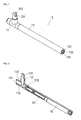
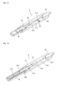
- the selected as embodiment energy storage device 1 comprises a secondary piston 12 receiving housing 11 which is connected to a clamping tube 13 and a concentrically arranged in this, a primary piston 15 receiving pressure pipe 14 is connected, which primary piston 15 in turn is in communication with a gas pressure spring 16.
- the housing 11 is formed substantially cylindrical. Approximately in the middle of the housing 11, a branch pipe 111 is formed orthogonal to this, whereby a T-shaped longitudinal section is formed.
- a threaded bore 113 is introduced into an end face of the housing 11 and is connected to the secondary cylinder space 112 via a connecting line 114.
- the housing 111 is provided concentrically with the threaded bore 113 with an external thread 115.
- a feed line 116 On its side opposite the threaded bore 113, a feed line 116, which is closed by a closure part 117, is furthermore arranged eccentrically in the housing 111.
- the housing 11 On both sides of the paragraph neck 111, the housing 11 is further provided with a sliding bearing ring 118.
- the secondary piston 12 has a substantially cylindrical shape and, at its end facing the secondary cylinder space 112, has a truncated cone shape, the outer contour of which essentially corresponds to the inner contour of the conical end of the secondary cylinder space 112 formed as a blind bore.
- two mutually spaced annular grooves 121 connect, each receiving an O-ring 122.
- a connecting piece 123 which is provided with a through bore 124.
- the clamping tube 13 is formed as a hollow cylinder and provided at its two ends with an internal thread 131, 132. At its end facing away from the housing 11, a threaded end 133 is screwed into the internal thread 132 of the clamping tube 13, which is provided with a tool engagement 134.
- the pressure tube 14 is formed as a hollow cylinder and provided at its end facing the housing 11 with an external thread 141, to which an annular groove 142 connects, which receives an O-ring 143.
- the primary piston 15 is substantially cylindrical and has an outer diameter which substantially corresponds to the inner diameter of the pressure tube 14. At its end facing the housing 11, a diameter-reduced portion 151 is integrally formed on the primary piston 15. Spaced to the reduced diameter portion 151, two annular grooves 152 are inserted in the secondary piston 12 in parallel with each other, each receiving an O-ring 153. At its end opposite the diameter-reduced section 151, the primary piston 15 has a countersink 154, the inner contour of which essentially corresponds to the end outer contour of the piston rod 161 of the gas spring 16 whose outer diameter is dimensioned to be slightly smaller than the outer diameter of the primary piston 15.
- the clamping tube 13 is screwed with its internal thread 131 on the external thread 115 of the housing 11 and is at the end of a sliding bearing ring 118 at.
- the pressure tube 14 is arranged concentrically to this and screwed with its external thread 141 in the threaded bore 113 of the housing 11, with which it forms a primary cylinder chamber 144.
- the pressure tube 14 is sealed with the O-ring 143 relative to the threaded bore 113.
- the primary piston 15 is arranged, on which the piston rod 161 of the gas spring 16 abuts, which gas pressure spring 16 is arranged in the clamping tube 13 and on the pressure tube 14 is present. With its opposite end of the piston rod 161, the gas spring 16 abuts against the threaded end 133.
- the secondary piston 12 whose outer diameter substantially corresponds to the inner diameter of the secondary cylinder space 112, is slidably disposed therein and sealed by the O-rings 122 against the secondary cylinder space 112.
- a suitable fluid for example a hydraulic oil, can now be introduced via the feed line 116, via which the secondary piston 12 is "connected" to the primary piston 15. If the secondary piston 12 is moved into the secondary cylinder space 112, the fluid is displaced, as a result of which the primary piston 15 and with it the piston rod 161 of the gas pressure spring 16 are moved in the direction of the threaded end piece 133. An opposite movement of the secondary piston 12 causes by the hereby indicated pressure change an opposite movement of the primary piston 15 and the associated therewith piston rod 161 of the gas spring 16th
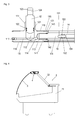
- the presentation counter 2 according to FIG. 4 comprises a body 21 with a cantilevered frame 22 to which a disc 3 is pivotally mounted via a fitting 4.
- the fitting 4 comprises a receiving profile 41 for the disc 3, at the spaced three first legs 42 are fixed, which are pivotally connected via pivot pins 45 to the second legs 43 of a mounting profile 44, which mounting profile 44 receives an energy storage device 1, the secondary piston 12th is connected via a connecting pin 47 with the first leg 42.
- the receiving profile 41 is provided over its entire length with a receiving groove 411 for receiving the disc 3, in which is arranged for bracing the disc 3 a retaining strip 412, which is clamped by a clamping screw 413 against the disc 3.
- the receiving profile 1 over its entire length on a projecting cover strip 414 on.
- the first leg 42 is arc-shaped and has a first bore 421 at its end opposite the receiving profile 41.
- the first bore 421 is preceded by a tab-like lever 422 integrally formed on the first leg 42, in which a second bore 423 is introduced.
- the second leg 43 is formed in the manner of a sliding block on which two webs 431, each having an undercut, are formed parallel to one another.
- an angled arm 432 is disposed opposite to a web 431 on the second leg.
- the second leg 43 has a bore 433 for receiving a pivot pin 45.
- the fastening profile 44 is formed by an abutment plate 441, which merges on one longitudinal side into an angularly adjusted support plate 442.
- the support plate 442 is provided with two mutually parallel, having an undercut grooves 443 which extend over the entire length of the support plate 442. Spaced to the support plate 442, a web 444 is integrally formed on the contact plate 441 over its entire length.
- the fastening profile 44 is fastened by means of screws 446 to the frame 22 of the body 21 of the presentation counter 2.
- the support plate 442 is formed bent at its free end and thus forms a stop for a horizontally mounted on the frame 22 glass plate 23.
- the grooves 443 of the support plate 442 spaced from each other three second legs 43 are inserted, wherein the webs 431 of the second leg 43rd engage in the grooves 443 of the support plate 442.
- the arms 432 of the second leg 43 bear against the web 444 of the fastening profile 44.
- the first legs 42 are pivotable about pivot pins 45 each having a second leg 43 connected, wherein the pivot pins 45 are guided through the bore 433 of the second leg 43 and the first bore 421 of the first leg 42 and secured by a locking plate 46.
- an energy storage device 1 of the type described above is arranged, the secondary piston 12 via a connecting pin 47, which is guided through the through hole 124 of the connecting piece 123 and the second bore 423 of the middle first leg 42.
- the energy storage device 1 within the fitting 4 of the presentation counter 2 only requires a minimum of installation space.
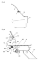
- FIG. 8 is a further embodiment of a presentation counter 2 ', shown.
- the disc 3 ' this presentation counter 2', pivotally connected to the lowermost front edge of the body 21 connected thereto. To "open" the disc 3 ', this can be swung down to the front.
- the disc 3 ' is connected to a fitting 5 in a further embodiment with the body 21.
- the fitting 5 comprises a receiving profile 51 for receiving the disc 3 ', which is pivotally connected to a fastening profile 52 connected to the body 21.
- the receiving profile 51 has a receiving groove 511 for receiving the disc 3 ', and merges into a first leg 512, on which a joint socket 513 is formed.
- a lever 514 which is attached at right angles to this is formed on the receiving profile 51 and has an eyelet 515 at its end.
- the lever 514 is provided centrally with a slot 516 for receiving the connecting piece 123 of the secondary piston 12 of the energy storage device 1.
- the fastening profile 52 has a substantially C-shaped cross-section. It comprises an abutment plate 521, which merges on a longitudinal side into a contact plate 522 which is set at right angles to this.
- the support plate 522 is in an approximately 45 ° to this second salary 523 on, on the end an eyelet 524 is formed. Opposite the support plate 522, the contact plate 521 goes over into a gutter piece 525.
- the first leg 512 of the receiving profile 51 is pivotally connected to the second leg 523 of the fastening profile 52, wherein the formed on the second leg 523 eyelet 524 engages in the socket 513 of the first leg 512.
- the energy storage device 1 is rotatably mounted via the slide bearing rings 118 in the gutter piece 525 of the fastening profile 52, wherein the connecting piece 123 of the secondary piston 12 engages in the slot 516 of the first leg 512, such that the through bore 124 of the connection piece 123 with the eyelet 515 of the first Leg 512 is aligned, through which a connecting pin 53 is guided.
- this fitting with arranged in this energy storage device 1 only a minimal space.
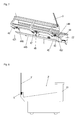
- the energy storage device 6 of the embodiment according to FIG. 13 corresponds largely to the energy storage device 6 according to FIG. 12 , wherein orthogonal to the connecting line 612 in the housing 61, a threaded bore 615 is introduced, which intersects the connecting line 612.
- an adjusting screw 65 is introduced, via which the cross section of the connecting line 612 is adjustable at this point.
- the energy storage device 6 according to FIG. 14 is largely the same as in FIG. 12 Instead of the gas spring 64 but here a cylinder 66 is screwed in the receptacle 614, in which a coil spring 661 is arranged, which is biased against an integrally formed on the piston rod 662 spring seat disc 663.
- energy storage device 7 comprises a housing 71, in which in the form of a stepped bore, a receptacle 711 is introduced for a gas spring 73, which merges into a reduced-diameter primary cylinder chamber 712, which in turn merges into a reduced-diameter connecting line 713, in which an orthogonal to this introduced into the housing 71 threaded bore 714 opens.
- a primary piston 72 is guided, which is connected to the piston rod 731 of a receiving 711 arranged in the gas spring 73.
- a secondary cylinder 74 having a secondary cylinder space 741 is screwed in via a screw connection pipe piece 742 integrally formed thereon.
- the connecting line 713 is connected to the secondary cylinder chamber 741 of the secondary cylinder 74.
- a secondary piston 75 is arranged in the secondary cylinder space 741.
- Such an articulated connection can be arranged both laterally, as well as elsewhere, in particular in alignment with the central axis of the primary cylinder space.
- the articulated connection is to be designed so that a continuous connecting line between primary cylinder space and secondary cylinder space exists.
- the energy storage device 8 of the embodiment according to FIG. 16 is similar to the one in FIG. 15 constructed energy storage device 7 constructed.
- the housing 81 is designed angled, is introduced in the right angle deflected leg of the secondary cylinder chamber 813, which opens into a right-angled kinking connecting line 812, which in turn merges into the primary cylinder chamber 811, which opens into the receptacle 814 for the gas spring 84.
- the arranged in the primary cylinder chamber 811 primary piston 82 is in turn connected to the piston rod 841 of the gas spring 84.
- the secondary piston 83 is guided in the secondary cylinder space 813 of the housing.
- the energy storage device 9 of the embodiment according to FIG. 17 includes a first housing 91 and a second housing 92, which are interconnected via a connecting line 93.
- the first housing 91 has in the form of a stepped bore a receptacle 911 for a gas pressure spring 96, which opens into a reduced-diameter primary cylinder chamber 912, which in turn merges via a conical taper in a diameter-reduced connection bore 913.
- the second housing 92 has a secondary cylinder space 921, again in the form of a stepped bore, which merges via a conical taper into a diameter-reduced connection bore 922.
- connection bore 922 Orthogonal to the connection bore 922, a threaded bore 923 is introduced into the second housing 92, which crosses the connection bore 922 and into which an adjusting screw 97 is screwed.
- the adjusting screw 97 in turn serves to change the cross section of the Connection hole 922 at this point.
- the first housing 91 and the second housing 92 are connected to one another via the connecting line 93, which is introduced at its one side into the connection bore 913 of the first housing 91 and at its other side into the connection bore 922 of the second housing 92. Via the hose-like flexible connection line 93, the primary cylinder space 912 is thus connected to the secondary cylinder space 921.
- the thus formed energy storage device 9 allows a very flexible space allocation, since in a fitting for pivotally mounting a disc on a presentation desk only the second housing 92 is to be accommodated.
- the first housing 91 can be arranged at any point in or on the presentation desk, wherein the length of the flexible connection line 93 is to be selected accordingly, which connection line 93 can be laid arbitrarily.
Landscapes
- Filling Or Discharging Of Gas Storage Vessels (AREA)
Priority Applications (1)
| Application Number | Priority Date | Filing Date | Title |
|---|---|---|---|
| EP15169009.6A EP3095939B1 (fr) | 2015-05-22 | 2015-05-22 | Dispositif d'accumulation d'énergie destiné à l'assistance au levage du mouvement de pivotement d'une plaque d'un comptoir de présentation |
Applications Claiming Priority (1)
| Application Number | Priority Date | Filing Date | Title |
|---|---|---|---|
| EP15169009.6A EP3095939B1 (fr) | 2015-05-22 | 2015-05-22 | Dispositif d'accumulation d'énergie destiné à l'assistance au levage du mouvement de pivotement d'une plaque d'un comptoir de présentation |
Publications (2)
| Publication Number | Publication Date |
|---|---|
| EP3095939A1 true EP3095939A1 (fr) | 2016-11-23 |
| EP3095939B1 EP3095939B1 (fr) | 2019-04-24 |
Family
ID=53264520
Family Applications (1)
| Application Number | Title | Priority Date | Filing Date |
|---|---|---|---|
| EP15169009.6A Not-in-force EP3095939B1 (fr) | 2015-05-22 | 2015-05-22 | Dispositif d'accumulation d'énergie destiné à l'assistance au levage du mouvement de pivotement d'une plaque d'un comptoir de présentation |
Country Status (1)
| Country | Link |
|---|---|
| EP (1) | EP3095939B1 (fr) |
Citations (4)
| Publication number | Priority date | Publication date | Assignee | Title |
|---|---|---|---|---|
| DE4402727C1 (de) | 1994-01-29 | 1995-06-14 | Vieler Gerd & Bernd Kg | Vorrichtung zur Schwenkbewegung einer Scheibe, insbesondere an Kühl- oder Verkaufstheken |
| DE10310930A1 (de) * | 2003-03-13 | 2004-09-30 | Daimlerchrysler Ag | Aktuatorsystem |
| WO2010102979A1 (fr) * | 2009-03-11 | 2010-09-16 | Kaba Gilgen Ag | Dispositif de rappel pour mécanisme d'entraînement de portes |
| DE202013102522U1 (de) | 2013-06-12 | 2013-06-19 | Vieler International Gmbh + Co. Kg | Beschlag für eine mit einer Scheibe versehenen Theke und Baugruppe hierzu |
-
2015
- 2015-05-22 EP EP15169009.6A patent/EP3095939B1/fr not_active Not-in-force
Patent Citations (5)
| Publication number | Priority date | Publication date | Assignee | Title |
|---|---|---|---|---|
| DE4402727C1 (de) | 1994-01-29 | 1995-06-14 | Vieler Gerd & Bernd Kg | Vorrichtung zur Schwenkbewegung einer Scheibe, insbesondere an Kühl- oder Verkaufstheken |
| EP0664987A1 (fr) * | 1994-01-29 | 1995-08-02 | Vieler International KG | Dispositif à pivotement d'un panneau de verr, en particulier pour comptoirs de vente (réfrigerés) |
| DE10310930A1 (de) * | 2003-03-13 | 2004-09-30 | Daimlerchrysler Ag | Aktuatorsystem |
| WO2010102979A1 (fr) * | 2009-03-11 | 2010-09-16 | Kaba Gilgen Ag | Dispositif de rappel pour mécanisme d'entraînement de portes |
| DE202013102522U1 (de) | 2013-06-12 | 2013-06-19 | Vieler International Gmbh + Co. Kg | Beschlag für eine mit einer Scheibe versehenen Theke und Baugruppe hierzu |
Also Published As
| Publication number | Publication date |
|---|---|
| EP3095939B1 (fr) | 2019-04-24 |
Similar Documents
| Publication | Publication Date | Title |
|---|---|---|
| AT518248B1 (de) | Möbelbeschlag | |
| DE20018361U1 (de) | Haltevorrichtung für ein Flüssig-Kristallbildschirm | |
| EP3230543A1 (fr) | Charnière de meuble | |
| EP3334881B1 (fr) | Goujon à ressort avec montage sans vissage | |
| DE68903342T2 (de) | Tuerschliesser. | |
| WO2018033221A1 (fr) | Charnière de meuble | |
| DE202017100244U1 (de) | Duschabtrennung mit einer durch eine Feder-Dämpfer-Einheit aktiv in die Endstellungen bewegbaren Schiebetür | |
| DE102015105130A1 (de) | Seitenzarge für einen Schubkasten und Verfahren zur Montage der Seitenzarge | |
| DE202014100431U1 (de) | Bandanordnung mit Justiermitteln | |
| DE19548202A1 (de) | Türschließer mit kontrolliertem Schließablauf | |
| DE102014010443A1 (de) | Schlauchquetschventil | |
| DE20200762U1 (de) | Scharnier für Möbel | |
| EP3095939B1 (fr) | Dispositif d'accumulation d'énergie destiné à l'assistance au levage du mouvement de pivotement d'une plaque d'un comptoir de présentation | |
| CH705157A2 (de) | Vorrichtung zum Ein- und Verstellen der Länge von teleskopartig aufgebauten Tischbeinen. | |
| DE202007011982U1 (de) | Verstellbares Band | |
| EP3695748A1 (fr) | Dispositif formant une armoire encastrée | |
| DE3217104C2 (fr) | ||
| EP2304146B1 (fr) | Dispositif d'orientation pour une fenetre, une porte ou similaire | |
| EP3655610B1 (fr) | Joint d'étanchéité à abaissement | |
| DE202004013401U1 (de) | Montageplatte zur verstellbaren Halterung von Möbelscharnieren am Korpus von Möbelstücken | |
| EP3073039B1 (fr) | Disposition de la fiche articulee | |
| DE102006051862B4 (de) | Laufwagen | |
| DE1708220C3 (de) | Scharnierband mit einer federbelasteten Raste für Türen | |
| DE3744295A1 (de) | Klemmvorrichtung zum festklemmen einer linear beweglichen stange | |
| DE202008008545U1 (de) | Verbindungsvorrichtung mit einem zwei Flansche umgreifenden Spannring |
Legal Events
| Date | Code | Title | Description |
|---|---|---|---|
| PUAI | Public reference made under article 153(3) epc to a published international application that has entered the european phase |
Free format text: ORIGINAL CODE: 0009012 |
|
| AK | Designated contracting states |
Kind code of ref document: A1 Designated state(s): AL AT BE BG CH CY CZ DE DK EE ES FI FR GB GR HR HU IE IS IT LI LT LU LV MC MK MT NL NO PL PT RO RS SE SI SK SM TR |
|
| AX | Request for extension of the european patent |
Extension state: BA ME |
|
| STAA | Information on the status of an ep patent application or granted ep patent |
Free format text: STATUS: REQUEST FOR EXAMINATION WAS MADE |
|
| 17P | Request for examination filed |
Effective date: 20170425 |
|
| RBV | Designated contracting states (corrected) |
Designated state(s): AL AT BE BG CH CY CZ DE DK EE ES FI FR GB GR HR HU IE IS IT LI LT LU LV MC MK MT NL NO PL PT RO RS SE SI SK SM TR |
|
| STAA | Information on the status of an ep patent application or granted ep patent |
Free format text: STATUS: EXAMINATION IS IN PROGRESS |
|
| 17Q | First examination report despatched |
Effective date: 20180702 |
|
| GRAP | Despatch of communication of intention to grant a patent |
Free format text: ORIGINAL CODE: EPIDOSNIGR1 |
|
| STAA | Information on the status of an ep patent application or granted ep patent |
Free format text: STATUS: GRANT OF PATENT IS INTENDED |
|
| RIC1 | Information provided on ipc code assigned before grant |
Ipc: A47F 3/00 20060101ALN20181004BHEP Ipc: E05F 1/10 20060101AFI20181004BHEP |
|
| RIC1 | Information provided on ipc code assigned before grant |
Ipc: A47F 3/00 20060101ALN20181018BHEP Ipc: E05F 1/10 20060101AFI20181018BHEP |
|
| INTG | Intention to grant announced |
Effective date: 20181029 |
|
| GRAJ | Information related to disapproval of communication of intention to grant by the applicant or resumption of examination proceedings by the epo deleted |
Free format text: ORIGINAL CODE: EPIDOSDIGR1 |
|
| STAA | Information on the status of an ep patent application or granted ep patent |
Free format text: STATUS: EXAMINATION IS IN PROGRESS |
|
| GRAP | Despatch of communication of intention to grant a patent |
Free format text: ORIGINAL CODE: EPIDOSNIGR1 |
|
| STAA | Information on the status of an ep patent application or granted ep patent |
Free format text: STATUS: GRANT OF PATENT IS INTENDED |
|
| INTC | Intention to grant announced (deleted) | ||
| RIC1 | Information provided on ipc code assigned before grant |
Ipc: E05F 1/10 20060101AFI20181219BHEP Ipc: A47F 3/00 20060101ALN20181219BHEP |
|
| INTG | Intention to grant announced |
Effective date: 20190109 |
|
| GRAS | Grant fee paid |
Free format text: ORIGINAL CODE: EPIDOSNIGR3 |
|
| GRAA | (expected) grant |
Free format text: ORIGINAL CODE: 0009210 |
|
| STAA | Information on the status of an ep patent application or granted ep patent |
Free format text: STATUS: THE PATENT HAS BEEN GRANTED |
|
| AK | Designated contracting states |
Kind code of ref document: B1 Designated state(s): AL AT BE BG CH CY CZ DE DK EE ES FI FR GB GR HR HU IE IS IT LI LT LU LV MC MK MT NL NO PL PT RO RS SE SI SK SM TR |
|
| REG | Reference to a national code |
Ref country code: GB Ref legal event code: FG4D Free format text: NOT ENGLISH |
|
| REG | Reference to a national code |
Ref country code: CH Ref legal event code: EP |
|
| REG | Reference to a national code |
Ref country code: AT Ref legal event code: REF Ref document number: 1124369 Country of ref document: AT Kind code of ref document: T Effective date: 20190515 Ref country code: IE Ref legal event code: FG4D Free format text: LANGUAGE OF EP DOCUMENT: GERMAN |
|
| REG | Reference to a national code |
Ref country code: DE Ref legal event code: R096 Ref document number: 502015008774 Country of ref document: DE |
|
| PGFP | Annual fee paid to national office [announced via postgrant information from national office to epo] |
Ref country code: DE Payment date: 20190521 Year of fee payment: 5 |
|
| REG | Reference to a national code |
Ref country code: NL Ref legal event code: MP Effective date: 20190424 |
|
| REG | Reference to a national code |
Ref country code: LT Ref legal event code: MG4D |
|
| PG25 | Lapsed in a contracting state [announced via postgrant information from national office to epo] |
Ref country code: NL Free format text: LAPSE BECAUSE OF FAILURE TO SUBMIT A TRANSLATION OF THE DESCRIPTION OR TO PAY THE FEE WITHIN THE PRESCRIBED TIME-LIMIT Effective date: 20190424 |
|
| PG25 | Lapsed in a contracting state [announced via postgrant information from national office to epo] |
Ref country code: ES Free format text: LAPSE BECAUSE OF FAILURE TO SUBMIT A TRANSLATION OF THE DESCRIPTION OR TO PAY THE FEE WITHIN THE PRESCRIBED TIME-LIMIT Effective date: 20190424 Ref country code: NO Free format text: LAPSE BECAUSE OF FAILURE TO SUBMIT A TRANSLATION OF THE DESCRIPTION OR TO PAY THE FEE WITHIN THE PRESCRIBED TIME-LIMIT Effective date: 20190724 Ref country code: FI Free format text: LAPSE BECAUSE OF FAILURE TO SUBMIT A TRANSLATION OF THE DESCRIPTION OR TO PAY THE FEE WITHIN THE PRESCRIBED TIME-LIMIT Effective date: 20190424 Ref country code: LT Free format text: LAPSE BECAUSE OF FAILURE TO SUBMIT A TRANSLATION OF THE DESCRIPTION OR TO PAY THE FEE WITHIN THE PRESCRIBED TIME-LIMIT Effective date: 20190424 Ref country code: HR Free format text: LAPSE BECAUSE OF FAILURE TO SUBMIT A TRANSLATION OF THE DESCRIPTION OR TO PAY THE FEE WITHIN THE PRESCRIBED TIME-LIMIT Effective date: 20190424 Ref country code: SE Free format text: LAPSE BECAUSE OF FAILURE TO SUBMIT A TRANSLATION OF THE DESCRIPTION OR TO PAY THE FEE WITHIN THE PRESCRIBED TIME-LIMIT Effective date: 20190424 Ref country code: PT Free format text: LAPSE BECAUSE OF FAILURE TO SUBMIT A TRANSLATION OF THE DESCRIPTION OR TO PAY THE FEE WITHIN THE PRESCRIBED TIME-LIMIT Effective date: 20190824 Ref country code: AL Free format text: LAPSE BECAUSE OF FAILURE TO SUBMIT A TRANSLATION OF THE DESCRIPTION OR TO PAY THE FEE WITHIN THE PRESCRIBED TIME-LIMIT Effective date: 20190424 |
|
| PG25 | Lapsed in a contracting state [announced via postgrant information from national office to epo] |
Ref country code: RS Free format text: LAPSE BECAUSE OF FAILURE TO SUBMIT A TRANSLATION OF THE DESCRIPTION OR TO PAY THE FEE WITHIN THE PRESCRIBED TIME-LIMIT Effective date: 20190424 Ref country code: LV Free format text: LAPSE BECAUSE OF FAILURE TO SUBMIT A TRANSLATION OF THE DESCRIPTION OR TO PAY THE FEE WITHIN THE PRESCRIBED TIME-LIMIT Effective date: 20190424 Ref country code: GR Free format text: LAPSE BECAUSE OF FAILURE TO SUBMIT A TRANSLATION OF THE DESCRIPTION OR TO PAY THE FEE WITHIN THE PRESCRIBED TIME-LIMIT Effective date: 20190725 Ref country code: PL Free format text: LAPSE BECAUSE OF FAILURE TO SUBMIT A TRANSLATION OF THE DESCRIPTION OR TO PAY THE FEE WITHIN THE PRESCRIBED TIME-LIMIT Effective date: 20190424 Ref country code: BG Free format text: LAPSE BECAUSE OF FAILURE TO SUBMIT A TRANSLATION OF THE DESCRIPTION OR TO PAY THE FEE WITHIN THE PRESCRIBED TIME-LIMIT Effective date: 20190724 |
|
| REG | Reference to a national code |
Ref country code: CH Ref legal event code: PL |
|
| PG25 | Lapsed in a contracting state [announced via postgrant information from national office to epo] |
Ref country code: IS Free format text: LAPSE BECAUSE OF FAILURE TO SUBMIT A TRANSLATION OF THE DESCRIPTION OR TO PAY THE FEE WITHIN THE PRESCRIBED TIME-LIMIT Effective date: 20190824 |
|
| REG | Reference to a national code |
Ref country code: DE Ref legal event code: R097 Ref document number: 502015008774 Country of ref document: DE |
|
| PG25 | Lapsed in a contracting state [announced via postgrant information from national office to epo] |
Ref country code: MC Free format text: LAPSE BECAUSE OF FAILURE TO SUBMIT A TRANSLATION OF THE DESCRIPTION OR TO PAY THE FEE WITHIN THE PRESCRIBED TIME-LIMIT Effective date: 20190424 Ref country code: CZ Free format text: LAPSE BECAUSE OF FAILURE TO SUBMIT A TRANSLATION OF THE DESCRIPTION OR TO PAY THE FEE WITHIN THE PRESCRIBED TIME-LIMIT Effective date: 20190424 Ref country code: RO Free format text: LAPSE BECAUSE OF FAILURE TO SUBMIT A TRANSLATION OF THE DESCRIPTION OR TO PAY THE FEE WITHIN THE PRESCRIBED TIME-LIMIT Effective date: 20190424 Ref country code: SK Free format text: LAPSE BECAUSE OF FAILURE TO SUBMIT A TRANSLATION OF THE DESCRIPTION OR TO PAY THE FEE WITHIN THE PRESCRIBED TIME-LIMIT Effective date: 20190424 Ref country code: LI Free format text: LAPSE BECAUSE OF NON-PAYMENT OF DUE FEES Effective date: 20190531 Ref country code: CH Free format text: LAPSE BECAUSE OF NON-PAYMENT OF DUE FEES Effective date: 20190531 Ref country code: EE Free format text: LAPSE BECAUSE OF FAILURE TO SUBMIT A TRANSLATION OF THE DESCRIPTION OR TO PAY THE FEE WITHIN THE PRESCRIBED TIME-LIMIT Effective date: 20190424 Ref country code: DK Free format text: LAPSE BECAUSE OF FAILURE TO SUBMIT A TRANSLATION OF THE DESCRIPTION OR TO PAY THE FEE WITHIN THE PRESCRIBED TIME-LIMIT Effective date: 20190424 |
|
| REG | Reference to a national code |
Ref country code: BE Ref legal event code: MM Effective date: 20190531 |
|
| PG25 | Lapsed in a contracting state [announced via postgrant information from national office to epo] |
Ref country code: LU Free format text: LAPSE BECAUSE OF NON-PAYMENT OF DUE FEES Effective date: 20190522 Ref country code: SM Free format text: LAPSE BECAUSE OF FAILURE TO SUBMIT A TRANSLATION OF THE DESCRIPTION OR TO PAY THE FEE WITHIN THE PRESCRIBED TIME-LIMIT Effective date: 20190424 Ref country code: IT Free format text: LAPSE BECAUSE OF FAILURE TO SUBMIT A TRANSLATION OF THE DESCRIPTION OR TO PAY THE FEE WITHIN THE PRESCRIBED TIME-LIMIT Effective date: 20190424 |
|
| PLBE | No opposition filed within time limit |
Free format text: ORIGINAL CODE: 0009261 |
|
| STAA | Information on the status of an ep patent application or granted ep patent |
Free format text: STATUS: NO OPPOSITION FILED WITHIN TIME LIMIT |
|
| GBPC | Gb: european patent ceased through non-payment of renewal fee |
Effective date: 20190724 |
|
| PG25 | Lapsed in a contracting state [announced via postgrant information from national office to epo] |
Ref country code: TR Free format text: LAPSE BECAUSE OF FAILURE TO SUBMIT A TRANSLATION OF THE DESCRIPTION OR TO PAY THE FEE WITHIN THE PRESCRIBED TIME-LIMIT Effective date: 20190424 |
|
| 26N | No opposition filed |
Effective date: 20200127 |
|
| PG25 | Lapsed in a contracting state [announced via postgrant information from national office to epo] |
Ref country code: GB Free format text: LAPSE BECAUSE OF NON-PAYMENT OF DUE FEES Effective date: 20190724 Ref country code: IE Free format text: LAPSE BECAUSE OF NON-PAYMENT OF DUE FEES Effective date: 20190522 |
|
| PG25 | Lapsed in a contracting state [announced via postgrant information from national office to epo] |
Ref country code: BE Free format text: LAPSE BECAUSE OF NON-PAYMENT OF DUE FEES Effective date: 20190531 Ref country code: SI Free format text: LAPSE BECAUSE OF FAILURE TO SUBMIT A TRANSLATION OF THE DESCRIPTION OR TO PAY THE FEE WITHIN THE PRESCRIBED TIME-LIMIT Effective date: 20190424 |
|
| PG25 | Lapsed in a contracting state [announced via postgrant information from national office to epo] |
Ref country code: FR Free format text: LAPSE BECAUSE OF NON-PAYMENT OF DUE FEES Effective date: 20190624 |
|
| REG | Reference to a national code |
Ref country code: DE Ref legal event code: R119 Ref document number: 502015008774 Country of ref document: DE |
|
| PG25 | Lapsed in a contracting state [announced via postgrant information from national office to epo] |
Ref country code: DE Free format text: LAPSE BECAUSE OF NON-PAYMENT OF DUE FEES Effective date: 20201201 Ref country code: CY Free format text: LAPSE BECAUSE OF FAILURE TO SUBMIT A TRANSLATION OF THE DESCRIPTION OR TO PAY THE FEE WITHIN THE PRESCRIBED TIME-LIMIT Effective date: 20190424 |
|
| REG | Reference to a national code |
Ref country code: AT Ref legal event code: MM01 Ref document number: 1124369 Country of ref document: AT Kind code of ref document: T Effective date: 20200522 |
|
| PG25 | Lapsed in a contracting state [announced via postgrant information from national office to epo] |
Ref country code: HU Free format text: LAPSE BECAUSE OF FAILURE TO SUBMIT A TRANSLATION OF THE DESCRIPTION OR TO PAY THE FEE WITHIN THE PRESCRIBED TIME-LIMIT; INVALID AB INITIO Effective date: 20150522 Ref country code: MT Free format text: LAPSE BECAUSE OF FAILURE TO SUBMIT A TRANSLATION OF THE DESCRIPTION OR TO PAY THE FEE WITHIN THE PRESCRIBED TIME-LIMIT Effective date: 20190424 |
|
| PG25 | Lapsed in a contracting state [announced via postgrant information from national office to epo] |
Ref country code: AT Free format text: LAPSE BECAUSE OF NON-PAYMENT OF DUE FEES Effective date: 20200522 |
|
| PG25 | Lapsed in a contracting state [announced via postgrant information from national office to epo] |
Ref country code: MK Free format text: LAPSE BECAUSE OF FAILURE TO SUBMIT A TRANSLATION OF THE DESCRIPTION OR TO PAY THE FEE WITHIN THE PRESCRIBED TIME-LIMIT Effective date: 20190424 |