EP3095946A1 - Schiebefenstervorrichtung - Google Patents
Schiebefenstervorrichtung Download PDFInfo
- Publication number
- EP3095946A1 EP3095946A1 EP15167987.5A EP15167987A EP3095946A1 EP 3095946 A1 EP3095946 A1 EP 3095946A1 EP 15167987 A EP15167987 A EP 15167987A EP 3095946 A1 EP3095946 A1 EP 3095946A1
- Authority
- EP
- European Patent Office
- Prior art keywords
- window
- side profile
- profile
- sliding window
- profile part
- Prior art date
- Legal status (The legal status is an assumption and is not a legal conclusion. Google has not performed a legal analysis and makes no representation as to the accuracy of the status listed.)
- Granted
Links
Images

Classifications
-
- E—FIXED CONSTRUCTIONS
- E06—DOORS, WINDOWS, SHUTTERS, OR ROLLER BLINDS IN GENERAL; LADDERS
- E06B—FIXED OR MOVABLE CLOSURES FOR OPENINGS IN BUILDINGS, VEHICLES, FENCES OR LIKE ENCLOSURES IN GENERAL, e.g. DOORS, WINDOWS, BLINDS, GATES
- E06B3/00—Window sashes, door leaves, or like elements for closing wall or like openings; Layout of fixed or moving closures, e.g. windows in wall or like openings; Features of rigidly-mounted outer frames relating to the mounting of wing frames
- E06B3/32—Arrangements of wings characterised by the manner of movement; Arrangements of movable wings in openings; Features of wings or frames relating solely to the manner of movement of the wing
- E06B3/34—Arrangements of wings characterised by the manner of movement; Arrangements of movable wings in openings; Features of wings or frames relating solely to the manner of movement of the wing with only one kind of movement
- E06B3/42—Sliding wings; Details of frames with respect to guiding
- E06B3/46—Horizontally-sliding wings
- E06B3/4681—Horizontally-sliding wings made of glass panes without frames
-
- E—FIXED CONSTRUCTIONS
- E05—LOCKS; KEYS; WINDOW OR DOOR FITTINGS; SAFES
- E05D—HINGES OR SUSPENSION DEVICES FOR DOORS, WINDOWS OR WINGS
- E05D15/00—Suspension arrangements for wings
- E05D15/06—Suspension arrangements for wings for wings sliding horizontally more or less in their own plane
- E05D15/0621—Details, e.g. suspension or supporting guides
- E05D15/066—Details, e.g. suspension or supporting guides for wings supported at the bottom
- E05D15/0686—Tracks
Definitions
- the invention relates to a sliding window device comprising a rectangular window frame for installation in a window opening according to the preamble of patent claim 1.
- the invention aims to remedy this situation. It is an object of the invention to provide a sliding window apparatus which provides frameless glazing, e.g. allows glazing without visible frame elements and which can be produced with minimal effort. According to the invention for this object achieved by a sliding window device with the features of the characterizing part of patent claim 1.
- a sliding window device which allows a frameless glazing and which can be produced with minimal effort.
- the peripheral profile is made of plastic and has at least two juxtaposed receptacles for receiving in each case a window element in its cross section, which recordings on put on an array of mutually parallel webs, a good thermal insulation is achieved. Thermal bridges are avoided.
- the inventive arrangement of mutually parallel webs are formed by the orthogonal to the receptacles extending channels that at least partially accommodate static elements, wherein on the bottom side profile part a base frame is arranged, the force introduction supports has, with directly in the channels static elements or indirectly connected such that they receive the loads acting on the static elements of the bottom-side profile part, a load is achieved via the force introduction supports the base frame.
- the load to be absorbed by the plastic profiles is minimized, whereby the execution of the circumferential profile of a continuous plastic profile is ever possible.
- the plastic profile according to the invention is inexpensive to produce and comparatively easy to work.
- the static elements can also be at least partially integrally formed on force introduction supports the base frame.
- base frame is functional in the present case.
- struts or columns could be cast within the window frame, which engage in the channels and thus achieve the required load transfer.
- the window frame designed in this way would have to be interpreted as a "basic frame”.
- Essential to the invention is the arrangement of static elements or supports that penetrate the plastic profile and absorb the load of the window elements.
- the base frame can be formed one or more parts.
- the static elements are at least partially formed by horizontally introduced into channels full profiles, for example by rectangular bar profiles.
- the assembly is easier.
- the stability of the arrangement is increased.
- recorded loads can also be distributed homogeneously over a plurality of force introduction supports of the base frame.
- the base frame is made of plastic. As a result, the material and manufacturing costs are further minimized. It can also be recycled plastic used for the production of the base frame.
- the transverse struts are partially replaced by rollers provided with bolts in the area of at least one receptacle, which preferably rest on force introduction supports the base frame.
- a friction-reduced sliding of a window element within the bottom-side profile part is achieved with simultaneous load application to the force introduction supports the base frame.
- a roller bar that is a bar provided with rollers arranged at uniform intervals, can be guided transversely to the transverse struts, wherein the roller bar is preferably engaged in recesses of the transverse struts.
- the roller bar is in any case designed such that it rests on at least one, preferably on two parallel arranged static elements.
- At least one window element is provided on its side facing the bottom profile side with a skirt which has a guide, in which engage the rollers, along which the window element is movable.
- the central support struts of the lateral sub-profiles are removed between the receptacles, whereby a continuous stop table is formed, which receives a stop profile.
- the stop profile is sealed by means of sealing elements against the stop table.
- a window element is firmly held by at least one receptacle of the bottom-side profile part, wherein this receptacle of the bottom-side profile part and the ceiling-side profile part is closed in the area outside of this window element in each case via a cover plate.
- a cover plate is integrally formed on the bottom-side profile and the cover-side profile.
- a tailor-made adaptation of the profile to the respectively fixed window element can be achieved in that a continuous cover plate is formed, which is partially removable for fitting the window element. Such a partial removal is possible due to the good workability of the plastic material with minimal effort.
- the sliding window device chosen as an exemplary embodiment consists essentially of a window frame 1, which is formed from a circumferential profile 2, that receives a fixed window element 3 and a displaceable window element 4 and is supported on the base side on a base frame 5.
- the encircling profile 2 is designed as a plastic profile and comprises a bottom-side profile part 21, a ceiling-side profile part 22 and two lateral profile parts 23 which delimit a rectangular window frame 1.
- the cross section of the circumferential profile 2 is in FIG. 4 shown.
- the profile 2 has two juxtaposed receptacles 24 for receiving in each case a window element 3, 4, wherein the receptacles 24 put on an array of mutually parallel webs 25 are formed by the orthogonal to the receptacles 24 extending channels 26.
- Parallel to the receptacles 24 are orthogonal to the channels 26, this penetrating upper transverse struts 27 and formed parallel to these lower transverse struts 28.
- the rollers 212 are arranged in a straight line between the channels 26.
- the required for the introduction of the bolt 211 slot is closed by a latchable in this cover 210 (see. FIG. 2 ).
- the bottom-side profile part 21 is mounted on the base frame 5.
- the base frame 5 has mutually parallel force introduction supports 52.
- the force introduction supports 51 in the region of the displaceable window element 4 receiving receptacle 24 are aligned with horizontally disposed in two sides of the rollers 212 channels 26 inserted, arranged in the form of rectangular bars static elements 51 arranged so that a load transfer via these static elements 51 takes place on the force introduction supports 52 ,
- no static elements 52 are introduced in the exemplary embodiment; the lower transverse struts 28 rest on the force introduction supports 52.
- load transmission via a static element 51 inserted into the channels 26 may also be useful here.
- the bolts 211 are directly on the static elements, whereby the load of several bolts on the static element 52 is evenly distributed to the force introduction supports 52 of the base frame 5.
- the two receptacles 24 are bounded on both sides by vertical support struts 29, which are aligned in the installed state of the bottom-side profile part 21 in a mounting gap 8 with the outer covering 81 and the upper floor 82 of the inner living area.
- the fixed window element 3 receiving receptacle 24 of the bottom-side profile part 21 is closed with a cover plate 213 which is integrally formed on the bottom-side profile part 21 and which extends up to the fixed window element 3.
- the cover-side profile part 22 is identical to the bottom-side profile part 21 is formed, however, the upper transverse struts 27 are not replaced by bolts. Also, the ceiling-side profile part 22 is not mounted on a base frame.
- the lateral profile parts 23 are formed corresponding to the cover-side profile part 22, wherein, however, located between the two receptacles 24 central support struts 29 are shortened to the bottom of the receptacles 24, whereby a continuous stop table 231 is formed, which receives a stop profile 6.
- the stop profile 6 is connected via latching pins 61 to the lateral profile part 23, wherein the locking pins 61 engage in the channels 26 of the lateral profile part 23.
- the stop profile 6 has substantially a rectangular cross section, which corresponds to the cross section of the stop table 231, wherein in the region of the displaceable window member 4 receiving receptacle 24 is a substantially cuboid inlet 62 is arranged to stop the sliding window element 4. Laterally, the stop profile 6 is sealed by means of sealing elements 7 against the support struts 29 of the lateral profile part 23.
- FIG. 7 the sliding window device according to the invention is shown in vertical section.
- the displaceable window element 4 is guided in the bottom-side profile part 21 and the opposite cover-side profile part 22.
- the displaceable window element 4 is provided with a border 41, which has a guide 42.
- the displaceable window element 4 rests on the rollers 212 of the bolts 211 of the base-side profile part 21 in such a way that the rollers 212 engage in the guide 42 of the enclosure 41 of the displaceable window element 4.
- the load of the displaceable window element 4 is transmitted via the rollers 212 to the pins 211, which rest on the static elements 52, which in turn rest on cross struts 28 on the force introduction struts 51 of the base frame 12, whereby the load is introduced to the base frame 5.
- the bottom-side profile part 21 is not loaded in this way; it serves only the lateral guidance by the recording 24 limiting support struts 29th
- the sliding window device is shown in a horizontal section.
- the fixed window element 3 is fixed between a lateral profile part 23 and two partial struts 111 of an intermediate strut 11 arranged centrally in the window frame 1.
- the sliding window element 4 is parallel to the fixed window element 3 between two partial struts 111 of the intermediate strut 11 on the rollers 212 of the bottom-side profile part 21 slidably and is in - gezeem - closed state at the inlet 62 of the stop profile 6 of the further lateral profile part 23 at.
- FIG. 6 a bottom-side profile part of another embodiment of a sliding window device is shown, which has a window frame with a fixed window element and two sliding window elements.
- the circumferential profile has three receptacles 24, wherein in the region of two receptacles 24, the upper transverse struts 27 are partially replaced by bolts 211 which receive rollers 212 on which the displaceable window elements 4 are mounted.
- the base frame 5 is correspondingly provided with force introduction struts 52, on which rest on the cross strut 28 static elements 51, on which in turn the provided with rollers 212 bolts 211 rest.
- the third receptacle 24 receives the fixed window element 3 and is correspondingly provided with a cover plate 213, which is integrally formed on the bottom-side profile part 21.
Landscapes
- Engineering & Computer Science (AREA)
- Civil Engineering (AREA)
- Structural Engineering (AREA)
- Wing Frames And Configurations (AREA)
Abstract
Description
- Die Erfindung betrifft eine Schiebefenstervorrichtung, umfassend einen rechteckigen Fensterrahmen zum Einbauen in einen Fensterausschnitt nach dem Oberbegriff des Patentanspruchs 1.
- Sehr große offenbare Fensterformate können nur als Schiebefenster ausgeführt werden. Um einen quasi nahtlosen Übergang zwischen Wohnraum und Natur zu erzielen, besteht häufig der Wunsch nach einer rahmenlosen Verglasung, d.h. einer Verglasung, bei der die Rahmen nicht sichtbar angeordnet sind. Hierzu werden Rahmenprofile vollständig in Boden, Decke und Wände eingepasst, welche die Fensterelemente aufnehmen. Dabei kommen regelmäßig Aluminiumprofile zum Einsatz, welche die erheblichen Lasten der Fensterelemente aufnehmen. Nachteilig an den bekannten Lösungen ist, dass aufgrund der hohen Wärmeleitfähigkeit des Aluminiumwerkstoffs mehrere Aluminiumprofile thermisch getrennt zum Einsatz kommen, wodurch der Aufwand erhöht ist. Zudem ist die Herstellung der regelmäßig stranggepressten Aluminiumprofile sehr kostenintensiv.
- Hier will die Erfindung Abhilfe schaffen. Der Erfindung liegt die Aufgabe zu Grunde, eine Schiebefenstervorrichtung bereitzustellen, die eine rahmenlose Verglasung, d.h. eine Verglasung ohne sichtbare Rahmenelemente ermöglicht und die aufwandminimiert herstellbar ist. Gemäß der Erfindung für diese Aufgabe durch eine Schiebefenstervorrichtung mit den Merkmalen des kennzeichnenden Teils des Patentanspruchs 1 gelöst.
- Mit der Erfindung ist eine Schiebefenstervorrichtung bereitgestellt, die eine rahmenlose Verglasung ermöglicht und die aufwandminimiert herstellbar ist. Dadurch, dass das umlaufende Profil aus Kunststoff hergestellt ist und in seinem Querschnitt wenigstens zwei nebeneinander angeordnete Aufnahmen zur Aufnahme jeweils eines Fensterelementes aufweist, welche Aufnahmen auf eine Anordnung von parallel zueinander angeordneten Stegen aufsetzen, ist eine gute Wärmeisolierung erzielt. Wärmebrücken sind so vermieden. Durch die erfindungsgemäße Anordnung von parallel zueinander angeordneten Stegen, durch die orthogonal zu den Aufnahmen sich erstreckende Kanäle gebildet sind, die zumindest teilweise Statikelemente aufnehmen, wobei an dem bodenseitigen Profilteil eine Basiszarge angeordnet ist, die Krafteinleitungsstützen aufweist, die mit in den Kanälen befindlichen Statikelementen direkt oder indirekt derart verbunden sind, dass sie die auf die Statikelemente des bodenseitigen Profilteils einwirkenden Lasten aufnehmen, ist eine Lastaufnahme über die Krafteinleitungsstützen der Basiszarge erzielt. Hierdurch ist die von den Kunststoffprofilen aufzunehmende Last minimiert, wodurch die Ausführung des umlaufenden Profils aus einem zusammenhängenden Kunststoffprofil überhaupt ermöglicht ist. Das erfindungsgemäße Kunststoffprofil ist kostengünstig herstellbar und vergleichsweise leicht zu bearbeiten. Dabei können die Statikelemente auch zumindest teilweise an Krafteinleitungsstützen der Basiszarge angeformt sein.
- Der Begriff "Basiszarge" ist vorliegend funktionell zu verstehen. Beispielsweise könnten innerhalb des Fensterrahmens auch Streben oder Stützen eingegossen sein, die in die Kanäle eingreifen und so die erforderliche Lastabtragung erzielen. An dieser Stelle wäre der so gestaltete Fensterrahmen als "Basiszarge" zu interpretieren. Erfindungswesentlich ist die Anordnung von Statikelementen bzw. Stützen, die das Kunststoffprofil durchdringen und die Last der Fensterelemente aufnehmen. Dabei kann die Basiszarge ein- oder mehrteilig ausgebildet sein.
- In Ausgestaltung der Erfindung sind die Statikelemente zumindest teilweise durch horizontal in Kanäle eingebrachte Vollprofile, beispielsweise durch Rechteck-Stangenprofile gebildet. Hierdurch ist die Montage erleichtert. Weiterhin ist die Stabilität der Anordnung erhöht. Durch ein solches Vollprofil können aufgenommene Lasten zudem homogen auf mehrere Krafteinleitungsstützen der Basiszarge verteilt werden.
- In Weiterbildung der Erfindung ist die Basiszarge aus Kunststoff hergestellt. Hierdurch sind die Material- und Herstellkosten weiter minimiert. Dabei kann für die Herstellung der Basiszarge auch Recyclingkunststoff zum Einsatz kommen.
- In Ausgestaltung der Erfindung sind beabstandet zu den Aufnahmen orthogonal zu den Kanälen und diese durchdringend Querstreben angeordnet, die bei dem bodenseitigen Profilteil zumindest bereichsweise auf den Krafteinleitungsstützen der Basiszarge aufliegen. Hierdurch ist eine direkte Lastübertragung auf die Krafteinleitungsstützen der Basiszarge bewirkt.
- In weiterer Ausgestaltung der Erfindung sind im Bereich wenigstens einer Aufnahme die Querstreben bereichsweise durch mit Rollen versehene Bolzen ersetzt, die vorzugsweise auf Krafteinleitungsstützen der Basiszarge aufliegen. Hierdurch ist ein reibungsvermindertes Gleiten eines Fensterelementes innerhalb des bodenseitigen Profilteils bei gleichzeitiger Lasteinleitung auf die Krafteinleitungsstützen der Basiszarge erzielt. Alternativ kann auch eine Rollenleiste, das heißt eine mit in gleichmäßigen Abständen angeordneten Rollen versehene Leiste quer zu den Querstreben durch diese geführt sein, wobei die Rollenleiste bevorzugt in Aussparungen der Querstreben eingerastet sind. Die Rollenleiste ist in jedem Fall derart auszubilden, dass sie auf wenigstens einem, bevorzugt auf zwei parallel zueinander angeordneten Statikelementen aufliegt.
- In Weiterbildung der Erfindung ist wenigstens ein Fensterelement an seiner dem bodenseitigen Profilteil zugewandten Seite mit einer Einfassung versehen, die eine Führung aufweist, in welche die Rollen eingreifen, entlang derer das Fensterelement verfahrbar ist. Hierdurch ist eine gute Führung des Fensterelementes innerhalb des bodenseitigen Profilteils erzielt.
- In Ausgestaltung der Erfindung sind die mittleren Stützstreben der seitlichen Teilprofile zwischen den Aufnahmen entfernt, wodurch eine durchgehende Anschlagnische gebildet ist, die ein Anschlagprofil aufnimmt. Hierdurch ist die Verwendung ein und desselben Profils zur Realisierung des Fensterrahmens ermöglicht. Die Entfernung der mittleren Stützstreben des Kunststoffprofils ist mit minimalem Aufwand ermöglicht.
- In Weiterbildung der Erfindung ist das Anschlagprofil über Dichtungselemente gegenüber der Anschlagnische abgedichtet. Hierdurch ist eine gute Wärmeisolierung der Schiebefenstervorrichtung bewirkt.
- In weiterer Ausgestaltung der Erfindung ist von wenigstens einer Aufnahme des bodenseitigen Profilteils ein Fensterelement fest aufgenommen, wobei diese Aufnahme des bodenseitigen Profilteils und des deckenseitigen Profilteils im Bereich außerhalb dieses Fensterelementes jeweils über eine Deckplatte verschlossen ist. Hierdurch ist eine durchgehende Ebene zwischen Wohnraum und Außenfläche erzielt, wodurch der Eindruck eines nahtlosen Übergangs zwischen Wohnraum und Natur bewirkt ist. Bevorzugt ist die Deckplatte an dem bodenseitigen Profil und dem deckenseitigen Profil jeweils angeformt. Eine passgenaue Anpassung des Profils an dem jeweils fest angeordneten Fensterelement ist dadurch erzielbar, dass eine durchgehende Deckplatte angeformt ist, die zur Einpassung des Fensterelementes bereichsweise entfernbar ist. Eine solche bereichsweise Entfernung ist aufgrund der guten Bearbeitbarkeit des Kunststoffmaterials mit minimalem Aufwand möglich.
- Andere Weiterbildungen und Ausgestaltungen der Erfindung sind in den übrigen Unteransprüchen angegeben. Ein Ausführungsbeispiel der Erfindung ist in den Zeichnungen dargestellt und wird nachfolgend im Einzelnen beschrieben. Es zeigen:
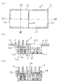
- Figur 1
- die schematische Darstellung einer Schiebefenstervorrichtung in der Ansicht;
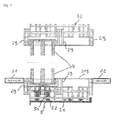
- Figur 2
- die schematische Darstellung des bodenseitigen Profilteils des Fensterrahmens der Schiebefenstervorrichtung aus
Figur 1 mit verschiebbarem Fensterelement im Querschnitt; - Figur 3
- die schematische Darstellung des bodenseitigen Profilteils des Fensterrahmens der Schiebefenstervorrichtung aus
Figur 1 mit verschiebbarem und festem Fensterelement im Querschnitt; - Figur 4
- die schematische Darstellung des Fensterrahmenprofils des Fensterrahmens der Schiebefenstervorrichtung aus
Figur 1 ; - Figur 5
- die schematische Darstellung eines seitlichen Profilteils des Fensterrahmens der Schiebefenstervorrichtung aus
Figur 1 mit anliegendem verschiebbaren Fensterelement; - Figur 6
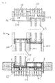
- die schematische Darstellung des bodenseitigen Profilteils eines Fensterrahmens einer Schiebefenstervorrichtung in einer weiteren Ausführungsform mit zwei verschiebbaren Fensterrahmen;
- Figur 7
- die schematische Darstellung des Fensterrahmens der Schiebefenstervorrichtung aus
Figur 1 im Schnitt VIII-VIII und - Figur 8
- die schematische Darstellung des Fensterrahmens der Schiebefenstervorrichtung aus
Figur 1 im Schnitt VIII-VIII. - Die als Ausführungsbeispiel gewählte Schiebefenstervorrichtung besteht im Wesentlichen aus einem Fensterrahmen 1, der aus einem umlaufenden Profil 2 gebildet ist, dass ein feststehendes Fensterelement 3 sowie ein verschiebbares Fensterelement 4 aufnimmt und bodenseitig auf einer Basiszarge 5 gelagert ist.
- Das umlaufende Profil 2 ist als Kunststoffprofil ausgebildet und umfasst ein bodenseitiges Profilteil 21, ein deckenseitiges Profilteil 22 sowie zwei seitliche Profilteile 23, welche einen rechteckförmigen Fensterrahmen 1 begrenzen. Der Querschnitt des umlaufenden Profils 2 ist in
Figur 4 dargestellt. Das Profil 2 weist zwei nebeneinander angeordnete Aufnahmen 24 zur Aufnahme jeweils eines Fensterelementes 3, 4 auf, wobei die Aufnahmen 24 auf eine Anordnung von parallel zueinander angeordneten Stegen 25 aufsetzen, durch die orthogonal zu den Aufnahmen 24 sich erstreckende Kanäle 26 gebildet sind. Parallel zu den Aufnahmen 24 sind orthogonal zu den Kanälen 26 diese durchdringend obere Querstreben 27 sowie parallel zu diesen untere Querstreben 28 angeformt. - Bei dem bodenseitigen Profilteil 21 sind die oberen Querstreben 27 im Bereich einer Aufnahme 24, die das verschiebbar Fensterelement 4 aufnimmt, bereichsweise durch Bolzen 211 ersetzt, welche jeweils eine Rolle 212 aufnehmen. Die Rollen 212 sind in einer Geraden fluchtend zwischen den Kanälen 26 angeordnet. Der zur Einführung des Bolzens 211 erforderliche Schlitz ist über eine in diesen einrastbare Abdeckung 210 verschlossen (vgl.
Figur 2 ). Das bodenseitige Profilteil 21 ist auf der Basiszarge 5 gelagert. Die Basiszarge 5 weist parallel zueinander angeordnete Krafteinleitungsstützen 52 auf. Dabei sind die Krafteinleitungsstützen 51 im Bereich der das verschiebbare Fensterelement 4 aufnehmenden Aufnahme 24 fluchtend mit horizontal in zwei beidseitig der Rollen 212 befindliche Kanäle 26 eingeschobene, in Form von Rechteckstäben ausgebildeten Statikelementen 51 angeordnet, sodass eine Lasteinleitung über diese Statikelemente 51 auf die Krafteinleitungsstützen 52 erfolgt. Im Bereich der das feststehende Fensterelement 3 aufnehmenden Aufnahme 24 sind im Ausführungsbeispiel keine Statikelemente 52 eingebracht; die unteren Querstreben 28 liegen auf den Krafteinleitungsstützen 52 auf. Je nach Last des feststehenden Fensterelementes kann auch hier ebenfalls eine Lastübertragung über ein in die Kanäle 26 eingeschobenes Statikelement 51 sinnvoll sein. Die Bolzen 211 liegen direkt auf den Statikelementen auf, wodurch die Last mehrerer Bolzen über das Statikelement 52 gleichmäßig auf die Krafteinleitungsstützen 52 der Basiszarge 5 verteilt wird. - Die beiden Aufnahmen 24 sind beidseitig durch vertikale Stützstreben 29 begrenzt, welche im eingebauten Zustand des bodenseitigen Profilteils 21 in einen Einbauspalt 8 mit dem Außenbelag 81 sowie dem Oberboden 82 des inneren Wohnbereichs fluchten. Die das feststehende Fensterelement 3 aufnehmende Aufnahme 24 des bodenseitigen Profilteils 21 ist mit einer Deckplatte 213 verschlossen, die an das bodenseitige Profilteils 21 angeformt ist und die sich bis zu dem feststehenden Fensterelement 3 erstreckt.
- Das deckenseitige Profilteil 22 ist identisch zum bodenseitigen Profilteil 21 ausgebildet, wobei jedoch die oberen Querstreben 27 nicht durch Bolzen ersetzt sind. Auch ist das deckenseitige Profilteil 22 nicht auf einer Basiszarge gelagert. Die seitlichen Profilteile 23 sind entsprechend dem deckenseitigen Profilteil 22 ausgebildet, wobei jedoch die zwischen den beiden Aufnahmen 24 befindlichen mittleren Stützstreben 29 bis auf den Grund der Aufnahmen 24 gekürzt sind, wodurch eine durchgehende Anschlagnische 231 gebildet ist, die ein Anschlagprofil 6 aufnimmt. Das Anschlagprofil 6 ist über Rastbolzen 61 mit dem seitlichen Profilteil 23 verbunden, wobei die Rastbolzen 61 in die Kanäle 26 des seitlichen Profilteils 23 eingreifen. Das Anschlagprofil 6 weist im Wesentlichen einen rechteckförmigen Querschnitt auf, der den Querschnitt der Anschlagnische 231 entspricht, wobei im Bereich der das verschiebbare Fensterelement 4 aufnehmenden Aufnahme 24 ein im Wesentlichen quaderförmiger Einlauf 62 zum Anschlag des verschiebbaren Fensterelementes 4 angeordnet ist. Seitlich ist das Anschlagprofil 6 über Dichtungselemente 7 gegenüber den Stützstreben 29 des seitlichen Profilteils 23 abgedichtet.
- In
Figur 7 ist die erfindungsgemäße Schiebefenstervorrichtung im Vertikalschnitt dargestellt. Das verschiebbare Fensterelement 4 ist in dem bodenseitigen Profilteil 21 sowie dem gegenüberliegenden deckenseitigen Profilteil 22 geführt. Bodenseitig ist das verschiebbare Fensterelement 4 mit einer Einfassung 41 versehen, die eine Führung 42 aufweist. Das verschiebbare Fensterelement 4 liegt auf den Rollen 212 der Bolzen 211 des bodenseitigen Profilteils 21 derart auf, dass die Rollen 212 in die Führung 42 der Einfassung 41 des verschiebbaren Fensterelements 4 eingreifen. Die Last des verschiebbaren Fensterelementes 4 wird über die Rollen 212 auf die Bolzen 211 übertragen, welche auf den Statikelementen 52 aufliegen, die wiederum über Querstreben28 auf den Krafteinleitungsstützen 51 der Basiszarge 12 aufliegen, wodurch die Last auf die Basiszarge 5 eingeleitet wird. Das bodenseitige Profilteil 21 wird auf diese Weise nicht belastet; es dient lediglich der seitlichen Führung durch die die Aufnahme 24 begrenzenden Stützstreben 29. - In
Figur 8 ist die Schiebefenstervorrichtung in einem horizontalen Schnitt dargestellt. Dabei ist das feststehende Fensterelement 3 zwischen einem seitlichen Profilteil 23 und zwei Teilstreben 111 einer mittig in dem Fensterrahmen 1 angeordneten Zwischenstrebe 11 fixiert. Das verschiebbare Fensterelement 4 ist parallel zu dem feststehenden Fensterelement 3 zwischen zwei Teilstreben 111 der Zwischenstrebe 11 auf den Rollen 212 des bodenseitigen Profilteils 21 verschiebbar und liegt in - dargestelltem - geschlossenen Zustand an dem Einlauf 62 des Anschlagprofils 6 des weiteren seitlichen Profilteils 23 an. - In
Figur 6 ist ein bodenseitiges Profilteil einer weiteren Ausführungsform einer Schiebefenstervorrichtung dargestellt, welches einen Fensterrahmen mit einem feststehenden Fensterelement sowie zwei verschiebbaren Fensterelemente aufweist. Hierzu weist das umlaufende Profil drei Aufnahmen 24 auf, wobei im Bereich von zwei Aufnahmen 24 die oberen Querstreben 27 bereichsweise durch Bolzen 211 ersetzt sind, die Rollen 212 aufnehmen, auf denen die verschiebbaren Fensterelemente 4 gelagert sind. Hierzu ist die Basiszarge 5 entsprechend mit Krafteinleitungsstützen 52 versehen, auf denen die über die Querstrebe 28 Statikelemente 51 aufliegen, auf denen wiederum die mit Rollen 212 versehenen Bolzen 211 aufliegen. Die dritte Aufnahme 24 nimmt das feststehende Fensterelement 3 auf und ist entsprechend mit einer Deckplatte 213 versehen, die an dem bodenseitigen Profilteil 21 angeformt ist.
Claims (13)
- Schiebefenstervorrichtung, umfassend einen rechteckigen Fensterrahmen zum Einbauen in einen Fensterausschnitt, in welchem Fensterrahmen wenigstens zwei Fensterelemente angeordnet sind, wobei der Fensterrahmen aus einem umlaufenden Profil gebildet ist, das ein bodenseitiges Profilteil, ein deckenseitiges Profilteil und zwei seitliche Profilteile umfasst, dadurch gekennzeichnet, dass das umlaufende Profil (2) aus Kunststoff hergestellt ist und in seinem Querschnitt wenigstens zwei nebeneinander angeordnete Aufnahmen (24) zur Aufnahme jeweils eines Fensterelementes (3, 4) aufweist, welche Aufnahmen (24) auf eine Anordnung von parallel zueinander angeordneten Stegen (25) aufsetzen, durch die orthogonal zu den Aufnahmen sich erstreckende Kanäle (26) gebildet sind, die zumindest teilweise Statikelemente (51) aufnehmen, wobei an dem bodenseitigen Profilteil (21) eine Basiszarge (5) angeordnet ist, die Krafteinleitungsstützen (52) aufweist, die mit in den Kanälen (26) befindlichen Statikelementen direkt oder indirekt derart verbunden sind, dass sie die auf die Statikelemente des bodenseitigen Profilteils (21) einwirkenden Lasten aufnehmen.
- Schiebefenstervorrichtung nach Anspruch 1, dadurch gekennzeichnet, dass die Statikelemente zumindest teilweise an Krafteinleitungsstützen der Basiszarge angeformt sind.
- Schiebefenstervorrichtung nach Anspruch 1, dadurch gekennzeichnet, dass die Statikelemente zumindest teilweise durch horizontal in Kanäle (26) eingebrachte Profile, insbesondere Vollprofile gebildet sind.
- Schiebefenstervorrichtung nach einem der vorgenannten Ansprüche, dadurch gekennzeichnet, dass die Basiszarge (5) aus Kunststoff hergestellt ist.
- Schiebefenstervorrichtung nach einem der vorgenannten Ansprüche, dadurch gekennzeichnet, dass beabstandet zu den Aufnahmen (24) orthogonal zu den Kanälen (26) und diese durchdringend Querstreben (27, 28) angeordnet sind, die bei dem bodenseitigen Profilteil (21) zumindest bereichsweise auf Krafteinleitungsstützen (51, 52) der Basiszarge (5) aufliegen.
- Schiebefenstervorrichtung nach Anspruch 5, dadurch gekennzeichnet, dass im Bereich wenigstens einer Aufnahme (24) die Querstreben (27) bereichsweise durch mit Rollen (212) versehene Bolzen (211) ersetzt sind.
- Schiebefenstervorrichtung nach Anspruch 6, dadurch gekennzeichnet, dass die Bolzen (211) direkt oder indirekt über Statikelemente (52) auf Krafteinleitungsstützen (51) der Basiszarge (5) aufliegen.
- Schiebefenstervorrichtung nach Anspruch 6 oder 7, dadurch gekennzeichnet, dass wenigstens ein Fensterelement (4) an seiner dem bodenseitigen Profilteil (219) zugewandten Seite mit einer Einfassung (41) versehen ist, die eine Führung (42) aufweist, in welche die Rollen (212) eingreifen, entlang derer das Fensterelement (4) verfahrbar ist.
- Schiebefenstervorrichtung nach einem der vorgenannten Ansprüche, dadurch gekennzeichnet, dass die Aufnahmen (24) durch vertikale Stützstreben (29) begrenzt sind, zwischen denen das jeweilige aufgenommene Fensterelement (3, 4) geführt ist.
- Schiebefenstervorrichtung nach einem der vorgenannten Ansprüche, dadurch gekennzeichnet, dass die mittleren Stützstreben (29) wenigstens eines seitlichen Teilprofils (23) zwischen den Aufnahmen (24) entfernt sind, wodurch eine durchgehende Anschlagnische (231) gebildet ist, die ein Anschlagprofil (6) aufnimmt.
- Schiebefenstervorrichtung nach Anspruch 10, dadurch gekennzeichnet, dass das Anschlagprofil (6) über Dichtungselemente (7) gegenüber der Anschlagnische (231) abgedichtet ist.
- Schiebefenstervorrichtung nach einem der vorgenannten Ansprüche, dadurch gekennzeichnet, dass von wenigstens einer Aufnahme (24) des bodenseitigen Profilteils (21) und des deckenseitigen Profils (23) ein Fensterelement (3) fest aufgenommen ist, wobei diese Aufnahme (24) des bodenseitigen Profils (21) und des deckenseitigen Profils (23) im Bereich außerhalb dieses Fensterelementes (3) jeweils über eine Deckplatte (213) verschlossen ist.
- Schiebefenstervorrichtung nach Anspruch 12, dadurch gekennzeichnet, dass die Deckplatte (213) an dem bodenseitigen Profil (21) und dem deckenseitigen Profil (23) jeweils angeformt ist.
Priority Applications (3)
| Application Number | Priority Date | Filing Date | Title |
|---|---|---|---|
| PL15167987T PL3095946T3 (pl) | 2015-05-18 | 2015-05-18 | Okno przesuwne |
| EP15167987.5A EP3095946B1 (de) | 2015-05-18 | 2015-05-18 | Schiebefenstervorrichtung |
| PCT/EP2016/057820 WO2016184610A1 (de) | 2015-05-18 | 2016-04-08 | Schiebefenstervorrichtung |
Applications Claiming Priority (1)
| Application Number | Priority Date | Filing Date | Title |
|---|---|---|---|
| EP15167987.5A EP3095946B1 (de) | 2015-05-18 | 2015-05-18 | Schiebefenstervorrichtung |
Publications (2)
| Publication Number | Publication Date |
|---|---|
| EP3095946A1 true EP3095946A1 (de) | 2016-11-23 |
| EP3095946B1 EP3095946B1 (de) | 2019-09-11 |
Family
ID=53177280
Family Applications (1)
| Application Number | Title | Priority Date | Filing Date |
|---|---|---|---|
| EP15167987.5A Active EP3095946B1 (de) | 2015-05-18 | 2015-05-18 | Schiebefenstervorrichtung |
Country Status (3)
| Country | Link |
|---|---|
| EP (1) | EP3095946B1 (de) |
| PL (1) | PL3095946T3 (de) |
| WO (1) | WO2016184610A1 (de) |
Cited By (6)
| Publication number | Priority date | Publication date | Assignee | Title |
|---|---|---|---|---|
| EP3859117A1 (de) * | 2020-01-29 | 2021-08-04 | Christian Michels | Schiebefenstervorrichtung |
| EP3872288A1 (de) | 2020-02-26 | 2021-09-01 | Christian Michels | Schiebefenstervorrichtung |
| EP3875714A1 (de) | 2020-03-06 | 2021-09-08 | Christian Michels | Schiebefenstervorrichtung |
| EP3879060A1 (de) | 2020-03-09 | 2021-09-15 | Christian Michels | Schiebefenstervorrichtung |
| EP4589103A1 (de) | 2024-01-22 | 2025-07-23 | Christian Michels | Verfahren zur herstellung eines fensterelements |
| EP4624718A1 (de) | 2024-03-26 | 2025-10-01 | Christian Michels | Schiebefenstervorrichtung |
Citations (2)
| Publication number | Priority date | Publication date | Assignee | Title |
|---|---|---|---|---|
| WO1988009423A1 (en) * | 1987-05-19 | 1988-12-01 | Wavin B.V. | Sliding window |
| US20120036810A1 (en) * | 2010-08-12 | 2012-02-16 | Orchidees Constructions S.A. | Framing for panels |
-
2015
- 2015-05-18 EP EP15167987.5A patent/EP3095946B1/de active Active
- 2015-05-18 PL PL15167987T patent/PL3095946T3/pl unknown
-
2016
- 2016-04-08 WO PCT/EP2016/057820 patent/WO2016184610A1/de not_active Ceased
Patent Citations (2)
| Publication number | Priority date | Publication date | Assignee | Title |
|---|---|---|---|---|
| WO1988009423A1 (en) * | 1987-05-19 | 1988-12-01 | Wavin B.V. | Sliding window |
| US20120036810A1 (en) * | 2010-08-12 | 2012-02-16 | Orchidees Constructions S.A. | Framing for panels |
Cited By (6)
| Publication number | Priority date | Publication date | Assignee | Title |
|---|---|---|---|---|
| EP3859117A1 (de) * | 2020-01-29 | 2021-08-04 | Christian Michels | Schiebefenstervorrichtung |
| EP3872288A1 (de) | 2020-02-26 | 2021-09-01 | Christian Michels | Schiebefenstervorrichtung |
| EP3875714A1 (de) | 2020-03-06 | 2021-09-08 | Christian Michels | Schiebefenstervorrichtung |
| EP3879060A1 (de) | 2020-03-09 | 2021-09-15 | Christian Michels | Schiebefenstervorrichtung |
| EP4589103A1 (de) | 2024-01-22 | 2025-07-23 | Christian Michels | Verfahren zur herstellung eines fensterelements |
| EP4624718A1 (de) | 2024-03-26 | 2025-10-01 | Christian Michels | Schiebefenstervorrichtung |
Also Published As
| Publication number | Publication date |
|---|---|
| PL3095946T3 (pl) | 2020-03-31 |
| WO2016184610A1 (de) | 2016-11-24 |
| EP3095946B1 (de) | 2019-09-11 |
Similar Documents
| Publication | Publication Date | Title |
|---|---|---|
| EP3095946B1 (de) | Schiebefenstervorrichtung | |
| EP2272142B1 (de) | Schaltschrank mit einer Bodenplatte | |
| EP2124302A1 (de) | Rahmengestell für eine Prüfzelle | |
| DE202010001518U1 (de) | Vorrichtung zur Aufnahme eines Solarmoduls, insbesondere Photovoltaikmodul | |
| EP2813657A1 (de) | Kunststoffprofil für eine Tür- und/oder Fenster-Rahmenbaugruppe die ein derartiges Kunststoffprofil umfasst | |
| DE202010013227U1 (de) | Flügel- und/oder Blendrahmen eines Fensters, einer Tür o.dgl. | |
| DE202015103439U1 (de) | Schiebefenstervorrichtung | |
| DE102014119021A1 (de) | Anordnung zum Befestigen eines Pfostens aus Kunststoff an einer Rahmenleiste eines Fensters oder einer Türe mittels eines Pfostenverbinders | |
| EP2878056B1 (de) | Unterirdischer schaltschrank für die elektroinstallation | |
| EP2767663A2 (de) | Verbindungsprofil zwischen einem Fenster- und/oder Türenrahmen und einer am Rahmen anliegenden Oberfläche | |
| EP0277569B1 (de) | Türflügel für Gehäuse und Schränke zum Einbau elektrischer Geräte und Verfahren zu seiner Herstellung | |
| EP2354432B1 (de) | Torblatt eines Schiebetors | |
| DE102009000643A1 (de) | Profilsystem für einen Kunststoff-Rollladenkasten | |
| EP2326494A1 (de) | Rahmenpresse mit führungssäulen | |
| EP3246211A1 (de) | Schiebetritt für ein fahrzeug, insbesondere für ein schienenfahrzeug | |
| DE7205256U (de) | Gehäuse für elektrische Schalt- und Vertefleranlagen | |
| AT400055B (de) | Rahmen für glasplatten oder andere plattenelemente zum bau von gebäudefassaden | |
| DE102013003718B4 (de) | Leichtmetall-Gehäuse aus Eckprofilen und Wandelementen | |
| DE19842296A1 (de) | Schutzzaun | |
| EP1643605B1 (de) | Geräteeinbaurahmen für Geräteeinbaukanäle | |
| DE102016218262A1 (de) | Dachfenster | |
| EP3299568A1 (de) | Dachfenster | |
| DE202007002705U1 (de) | Schließelement für eine Wandöffnung, insbesondere Tür für eine Zugangsöffnung in ein Haus | |
| EP3128112A1 (de) | Stützkonsole für ein rahmenprofil eines fensters oder einer tür | |
| EP3258048B1 (de) | Vorrichtung zum niederhalten eines abdeckblechs |
Legal Events
| Date | Code | Title | Description |
|---|---|---|---|
| PUAI | Public reference made under article 153(3) epc to a published international application that has entered the european phase |
Free format text: ORIGINAL CODE: 0009012 |
|
| AK | Designated contracting states |
Kind code of ref document: A1 Designated state(s): AL AT BE BG CH CY CZ DE DK EE ES FI FR GB GR HR HU IE IS IT LI LT LU LV MC MK MT NL NO PL PT RO RS SE SI SK SM TR |
|
| AX | Request for extension of the european patent |
Extension state: BA ME |
|
| STAA | Information on the status of an ep patent application or granted ep patent |
Free format text: STATUS: REQUEST FOR EXAMINATION WAS MADE |
|
| 17P | Request for examination filed |
Effective date: 20170517 |
|
| RBV | Designated contracting states (corrected) |
Designated state(s): AL AT BE BG CH CY CZ DE DK EE ES FI FR GB GR HR HU IE IS IT LI LT LU LV MC MK MT NL NO PL PT RO RS SE SI SK SM TR |
|
| GRAP | Despatch of communication of intention to grant a patent |
Free format text: ORIGINAL CODE: EPIDOSNIGR1 |
|
| STAA | Information on the status of an ep patent application or granted ep patent |
Free format text: STATUS: GRANT OF PATENT IS INTENDED |
|
| INTG | Intention to grant announced |
Effective date: 20190328 |
|
| GRAS | Grant fee paid |
Free format text: ORIGINAL CODE: EPIDOSNIGR3 |
|
| GRAJ | Information related to disapproval of communication of intention to grant by the applicant or resumption of examination proceedings by the epo deleted |
Free format text: ORIGINAL CODE: EPIDOSDIGR1 |
|
| GRAL | Information related to payment of fee for publishing/printing deleted |
Free format text: ORIGINAL CODE: EPIDOSDIGR3 |
|
| STAA | Information on the status of an ep patent application or granted ep patent |
Free format text: STATUS: REQUEST FOR EXAMINATION WAS MADE |
|
| GRAR | Information related to intention to grant a patent recorded |
Free format text: ORIGINAL CODE: EPIDOSNIGR71 |
|
| STAA | Information on the status of an ep patent application or granted ep patent |
Free format text: STATUS: GRANT OF PATENT IS INTENDED |
|
| GRAA | (expected) grant |
Free format text: ORIGINAL CODE: 0009210 |
|
| STAA | Information on the status of an ep patent application or granted ep patent |
Free format text: STATUS: THE PATENT HAS BEEN GRANTED |
|
| INTC | Intention to grant announced (deleted) | ||
| AK | Designated contracting states |
Kind code of ref document: B1 Designated state(s): AL AT BE BG CH CY CZ DE DK EE ES FI FR GB GR HR HU IE IS IT LI LT LU LV MC MK MT NL NO PL PT RO RS SE SI SK SM TR |
|
| INTG | Intention to grant announced |
Effective date: 20190806 |
|
| REG | Reference to a national code |
Ref country code: GB Ref legal event code: FG4D Free format text: NOT ENGLISH |
|
| REG | Reference to a national code |
Ref country code: CH Ref legal event code: EP |
|
| REG | Reference to a national code |
Ref country code: AT Ref legal event code: REF Ref document number: 1178670 Country of ref document: AT Kind code of ref document: T Effective date: 20190915 |
|
| REG | Reference to a national code |
Ref country code: DE Ref legal event code: R096 Ref document number: 502015010293 Country of ref document: DE Ref country code: IE Ref legal event code: FG4D Free format text: LANGUAGE OF EP DOCUMENT: GERMAN |
|
| REG | Reference to a national code |
Ref country code: CH Ref legal event code: NV Representative=s name: DR.-ING. ULRICH KOETTER, CH |
|
| REG | Reference to a national code |
Ref country code: SE Ref legal event code: TRGR |
|
| REG | Reference to a national code |
Ref country code: NL Ref legal event code: MP Effective date: 20190911 |
|
| REG | Reference to a national code |
Ref country code: LT Ref legal event code: MG4D |
|
| PG25 | Lapsed in a contracting state [announced via postgrant information from national office to epo] |
Ref country code: NO Free format text: LAPSE BECAUSE OF FAILURE TO SUBMIT A TRANSLATION OF THE DESCRIPTION OR TO PAY THE FEE WITHIN THE PRESCRIBED TIME-LIMIT Effective date: 20191211 Ref country code: FI Free format text: LAPSE BECAUSE OF FAILURE TO SUBMIT A TRANSLATION OF THE DESCRIPTION OR TO PAY THE FEE WITHIN THE PRESCRIBED TIME-LIMIT Effective date: 20190911 Ref country code: LT Free format text: LAPSE BECAUSE OF FAILURE TO SUBMIT A TRANSLATION OF THE DESCRIPTION OR TO PAY THE FEE WITHIN THE PRESCRIBED TIME-LIMIT Effective date: 20190911 Ref country code: HR Free format text: LAPSE BECAUSE OF FAILURE TO SUBMIT A TRANSLATION OF THE DESCRIPTION OR TO PAY THE FEE WITHIN THE PRESCRIBED TIME-LIMIT Effective date: 20190911 Ref country code: BG Free format text: LAPSE BECAUSE OF FAILURE TO SUBMIT A TRANSLATION OF THE DESCRIPTION OR TO PAY THE FEE WITHIN THE PRESCRIBED TIME-LIMIT Effective date: 20191211 |
|
| PG25 | Lapsed in a contracting state [announced via postgrant information from national office to epo] |
Ref country code: AL Free format text: LAPSE BECAUSE OF FAILURE TO SUBMIT A TRANSLATION OF THE DESCRIPTION OR TO PAY THE FEE WITHIN THE PRESCRIBED TIME-LIMIT Effective date: 20190911 Ref country code: ES Free format text: LAPSE BECAUSE OF FAILURE TO SUBMIT A TRANSLATION OF THE DESCRIPTION OR TO PAY THE FEE WITHIN THE PRESCRIBED TIME-LIMIT Effective date: 20190911 Ref country code: LV Free format text: LAPSE BECAUSE OF FAILURE TO SUBMIT A TRANSLATION OF THE DESCRIPTION OR TO PAY THE FEE WITHIN THE PRESCRIBED TIME-LIMIT Effective date: 20190911 Ref country code: RS Free format text: LAPSE BECAUSE OF FAILURE TO SUBMIT A TRANSLATION OF THE DESCRIPTION OR TO PAY THE FEE WITHIN THE PRESCRIBED TIME-LIMIT Effective date: 20190911 Ref country code: GR Free format text: LAPSE BECAUSE OF FAILURE TO SUBMIT A TRANSLATION OF THE DESCRIPTION OR TO PAY THE FEE WITHIN THE PRESCRIBED TIME-LIMIT Effective date: 20191212 |
|
| PG25 | Lapsed in a contracting state [announced via postgrant information from national office to epo] |
Ref country code: RO Free format text: LAPSE BECAUSE OF FAILURE TO SUBMIT A TRANSLATION OF THE DESCRIPTION OR TO PAY THE FEE WITHIN THE PRESCRIBED TIME-LIMIT Effective date: 20190911 Ref country code: PT Free format text: LAPSE BECAUSE OF FAILURE TO SUBMIT A TRANSLATION OF THE DESCRIPTION OR TO PAY THE FEE WITHIN THE PRESCRIBED TIME-LIMIT Effective date: 20200113 Ref country code: NL Free format text: LAPSE BECAUSE OF FAILURE TO SUBMIT A TRANSLATION OF THE DESCRIPTION OR TO PAY THE FEE WITHIN THE PRESCRIBED TIME-LIMIT Effective date: 20190911 Ref country code: EE Free format text: LAPSE BECAUSE OF FAILURE TO SUBMIT A TRANSLATION OF THE DESCRIPTION OR TO PAY THE FEE WITHIN THE PRESCRIBED TIME-LIMIT Effective date: 20190911 |
|
| PG25 | Lapsed in a contracting state [announced via postgrant information from national office to epo] |
Ref country code: IS Free format text: LAPSE BECAUSE OF FAILURE TO SUBMIT A TRANSLATION OF THE DESCRIPTION OR TO PAY THE FEE WITHIN THE PRESCRIBED TIME-LIMIT Effective date: 20200224 Ref country code: CZ Free format text: LAPSE BECAUSE OF FAILURE TO SUBMIT A TRANSLATION OF THE DESCRIPTION OR TO PAY THE FEE WITHIN THE PRESCRIBED TIME-LIMIT Effective date: 20190911 Ref country code: SM Free format text: LAPSE BECAUSE OF FAILURE TO SUBMIT A TRANSLATION OF THE DESCRIPTION OR TO PAY THE FEE WITHIN THE PRESCRIBED TIME-LIMIT Effective date: 20190911 Ref country code: SK Free format text: LAPSE BECAUSE OF FAILURE TO SUBMIT A TRANSLATION OF THE DESCRIPTION OR TO PAY THE FEE WITHIN THE PRESCRIBED TIME-LIMIT Effective date: 20190911 |
|
| REG | Reference to a national code |
Ref country code: DE Ref legal event code: R097 Ref document number: 502015010293 Country of ref document: DE |
|
| PLBE | No opposition filed within time limit |
Free format text: ORIGINAL CODE: 0009261 |
|
| STAA | Information on the status of an ep patent application or granted ep patent |
Free format text: STATUS: NO OPPOSITION FILED WITHIN TIME LIMIT |
|
| PG2D | Information on lapse in contracting state deleted |
Ref country code: IS |
|
| PG25 | Lapsed in a contracting state [announced via postgrant information from national office to epo] |
Ref country code: DK Free format text: LAPSE BECAUSE OF FAILURE TO SUBMIT A TRANSLATION OF THE DESCRIPTION OR TO PAY THE FEE WITHIN THE PRESCRIBED TIME-LIMIT Effective date: 20190911 Ref country code: IS Free format text: LAPSE BECAUSE OF FAILURE TO SUBMIT A TRANSLATION OF THE DESCRIPTION OR TO PAY THE FEE WITHIN THE PRESCRIBED TIME-LIMIT Effective date: 20200112 |
|
| 26N | No opposition filed |
Effective date: 20200615 |
|
| PG25 | Lapsed in a contracting state [announced via postgrant information from national office to epo] |
Ref country code: SI Free format text: LAPSE BECAUSE OF FAILURE TO SUBMIT A TRANSLATION OF THE DESCRIPTION OR TO PAY THE FEE WITHIN THE PRESCRIBED TIME-LIMIT Effective date: 20190911 |
|
| PG25 | Lapsed in a contracting state [announced via postgrant information from national office to epo] |
Ref country code: MC Free format text: LAPSE BECAUSE OF FAILURE TO SUBMIT A TRANSLATION OF THE DESCRIPTION OR TO PAY THE FEE WITHIN THE PRESCRIBED TIME-LIMIT Effective date: 20190911 |
|
| PG25 | Lapsed in a contracting state [announced via postgrant information from national office to epo] |
Ref country code: LU Free format text: LAPSE BECAUSE OF NON-PAYMENT OF DUE FEES Effective date: 20200518 |
|
| PG25 | Lapsed in a contracting state [announced via postgrant information from national office to epo] |
Ref country code: IE Free format text: LAPSE BECAUSE OF NON-PAYMENT OF DUE FEES Effective date: 20200518 |
|
| PG25 | Lapsed in a contracting state [announced via postgrant information from national office to epo] |
Ref country code: MT Free format text: LAPSE BECAUSE OF FAILURE TO SUBMIT A TRANSLATION OF THE DESCRIPTION OR TO PAY THE FEE WITHIN THE PRESCRIBED TIME-LIMIT Effective date: 20190911 Ref country code: CY Free format text: LAPSE BECAUSE OF FAILURE TO SUBMIT A TRANSLATION OF THE DESCRIPTION OR TO PAY THE FEE WITHIN THE PRESCRIBED TIME-LIMIT Effective date: 20190911 |
|
| PG25 | Lapsed in a contracting state [announced via postgrant information from national office to epo] |
Ref country code: MK Free format text: LAPSE BECAUSE OF FAILURE TO SUBMIT A TRANSLATION OF THE DESCRIPTION OR TO PAY THE FEE WITHIN THE PRESCRIBED TIME-LIMIT Effective date: 20190911 |
|
| P01 | Opt-out of the competence of the unified patent court (upc) registered |
Effective date: 20230513 |
|
| PGFP | Annual fee paid to national office [announced via postgrant information from national office to epo] |
Ref country code: GB Payment date: 20240620 Year of fee payment: 10 |
|
| PGFP | Annual fee paid to national office [announced via postgrant information from national office to epo] |
Ref country code: CH Payment date: 20240620 Year of fee payment: 10 |
|
| PGFP | Annual fee paid to national office [announced via postgrant information from national office to epo] |
Ref country code: AT Payment date: 20240529 Year of fee payment: 10 |
|
| PGFP | Annual fee paid to national office [announced via postgrant information from national office to epo] |
Ref country code: FR Payment date: 20240529 Year of fee payment: 10 |
|
| PGFP | Annual fee paid to national office [announced via postgrant information from national office to epo] |
Ref country code: PL Payment date: 20240607 Year of fee payment: 10 |
|
| PGFP | Annual fee paid to national office [announced via postgrant information from national office to epo] |
Ref country code: TR Payment date: 20240605 Year of fee payment: 10 Ref country code: SE Payment date: 20240529 Year of fee payment: 10 Ref country code: BE Payment date: 20240529 Year of fee payment: 10 |
|
| PGFP | Annual fee paid to national office [announced via postgrant information from national office to epo] |
Ref country code: IT Payment date: 20240528 Year of fee payment: 10 |
|
| REG | Reference to a national code |
Ref country code: CH Ref legal event code: H13 Free format text: ST27 STATUS EVENT CODE: U-0-0-H10-H13 (AS PROVIDED BY THE NATIONAL OFFICE) Effective date: 20251223 |
|
| PG25 | Lapsed in a contracting state [announced via postgrant information from national office to epo] |
Ref country code: AT Free format text: LAPSE BECAUSE OF NON-PAYMENT OF DUE FEES Effective date: 20250518 |
|
| REG | Reference to a national code |
Ref country code: AT Ref legal event code: MM01 Ref document number: 1178670 Country of ref document: AT Kind code of ref document: T Effective date: 20250518 |
|
| PG25 | Lapsed in a contracting state [announced via postgrant information from national office to epo] |
Ref country code: CH Free format text: LAPSE BECAUSE OF NON-PAYMENT OF DUE FEES Effective date: 20250531 |
|
| PG25 | Lapsed in a contracting state [announced via postgrant information from national office to epo] |
Ref country code: SE Free format text: LAPSE BECAUSE OF NON-PAYMENT OF DUE FEES Effective date: 20250519 |
|
| REG | Reference to a national code |
Ref country code: SE Ref legal event code: EUG |
|
| GBPC | Gb: european patent ceased through non-payment of renewal fee |
Effective date: 20250518 |
|
| REG | Reference to a national code |
Ref country code: BE Ref legal event code: MM Effective date: 20250531 |
|
| PG25 | Lapsed in a contracting state [announced via postgrant information from national office to epo] |
Ref country code: GB Free format text: LAPSE BECAUSE OF NON-PAYMENT OF DUE FEES Effective date: 20250518 |
|
| PG25 | Lapsed in a contracting state [announced via postgrant information from national office to epo] |
Ref country code: BE Free format text: LAPSE BECAUSE OF NON-PAYMENT OF DUE FEES Effective date: 20250531 Ref country code: IT Free format text: LAPSE BECAUSE OF NON-PAYMENT OF DUE FEES Effective date: 20250518 |
|
| PG25 | Lapsed in a contracting state [announced via postgrant information from national office to epo] |
Ref country code: FR Free format text: LAPSE BECAUSE OF NON-PAYMENT OF DUE FEES Effective date: 20250531 |
|
| PG25 | Lapsed in a contracting state [announced via postgrant information from national office to epo] |
Ref country code: PL Free format text: LAPSE BECAUSE OF NON-PAYMENT OF DUE FEES Effective date: 20250518 |
|
| PGFP | Annual fee paid to national office [announced via postgrant information from national office to epo] |
Ref country code: DE Payment date: 20260504 Year of fee payment: 12 |