EP3095958B1 - System zur thermischen abschirmung eines abschnitts eines gasturbinenmantelanordnung - Google Patents
System zur thermischen abschirmung eines abschnitts eines gasturbinenmantelanordnung Download PDFInfo
- Publication number
- EP3095958B1 EP3095958B1 EP16159096.3A EP16159096A EP3095958B1 EP 3095958 B1 EP3095958 B1 EP 3095958B1 EP 16159096 A EP16159096 A EP 16159096A EP 3095958 B1 EP3095958 B1 EP 3095958B1
- Authority
- EP
- European Patent Office
- Prior art keywords
- turbine
- shroud
- shroud seal
- forward wall
- thermal shield
- Prior art date
- Legal status (The legal status is an assumption and is not a legal conclusion. Google has not performed a legal analysis and makes no representation as to the accuracy of the status listed.)
- Active
Links
Images


Classifications
-
- F—MECHANICAL ENGINEERING; LIGHTING; HEATING; WEAPONS; BLASTING
- F01—MACHINES OR ENGINES IN GENERAL; ENGINE PLANTS IN GENERAL; STEAM ENGINES
- F01D—NON-POSITIVE DISPLACEMENT MACHINES OR ENGINES, e.g. STEAM TURBINES
- F01D25/00—Component parts, details, or accessories, not provided for in, or of interest apart from, other groups
- F01D25/08—Cooling; Heating; Heat-insulation
- F01D25/14—Casings modified therefor
- F01D25/145—Thermally insulated casings
-
- F—MECHANICAL ENGINEERING; LIGHTING; HEATING; WEAPONS; BLASTING
- F02—COMBUSTION ENGINES; HOT-GAS OR COMBUSTION-PRODUCT ENGINE PLANTS
- F02C—GAS-TURBINE PLANTS; AIR INTAKES FOR JET-PROPULSION PLANTS; CONTROLLING FUEL SUPPLY IN AIR-BREATHING JET-PROPULSION PLANTS
- F02C7/00—Features, components parts, details or accessories, not provided for in, or of interest apart form groups F02C1/00 - F02C6/00; Air intakes for jet-propulsion plants
- F02C7/24—Heat or noise insulation
-
- F—MECHANICAL ENGINEERING; LIGHTING; HEATING; WEAPONS; BLASTING
- F01—MACHINES OR ENGINES IN GENERAL; ENGINE PLANTS IN GENERAL; STEAM ENGINES
- F01D—NON-POSITIVE DISPLACEMENT MACHINES OR ENGINES, e.g. STEAM TURBINES
- F01D11/00—Preventing or minimising internal leakage of working-fluid, e.g. between stages
- F01D11/005—Sealing means between non relatively rotating elements
-
- F—MECHANICAL ENGINEERING; LIGHTING; HEATING; WEAPONS; BLASTING
- F01—MACHINES OR ENGINES IN GENERAL; ENGINE PLANTS IN GENERAL; STEAM ENGINES
- F01D—NON-POSITIVE DISPLACEMENT MACHINES OR ENGINES, e.g. STEAM TURBINES
- F01D11/00—Preventing or minimising internal leakage of working-fluid, e.g. between stages
- F01D11/08—Preventing or minimising internal leakage of working-fluid, e.g. between stages for sealing space between rotor blade tips and stator
-
- F—MECHANICAL ENGINEERING; LIGHTING; HEATING; WEAPONS; BLASTING
- F01—MACHINES OR ENGINES IN GENERAL; ENGINE PLANTS IN GENERAL; STEAM ENGINES
- F01D—NON-POSITIVE DISPLACEMENT MACHINES OR ENGINES, e.g. STEAM TURBINES
- F01D25/00—Component parts, details, or accessories, not provided for in, or of interest apart from, other groups
- F01D25/08—Cooling; Heating; Heat-insulation
-
- F—MECHANICAL ENGINEERING; LIGHTING; HEATING; WEAPONS; BLASTING
- F01—MACHINES OR ENGINES IN GENERAL; ENGINE PLANTS IN GENERAL; STEAM ENGINES
- F01D—NON-POSITIVE DISPLACEMENT MACHINES OR ENGINES, e.g. STEAM TURBINES
- F01D5/00—Blades; Blade-carrying members; Heating, heat-insulating, cooling or antivibration means on the blades or the members
- F01D5/02—Blade-carrying members, e.g. rotors
- F01D5/08—Heating, heat-insulating or cooling means
-
- F—MECHANICAL ENGINEERING; LIGHTING; HEATING; WEAPONS; BLASTING
- F02—COMBUSTION ENGINES; HOT-GAS OR COMBUSTION-PRODUCT ENGINE PLANTS
- F02C—GAS-TURBINE PLANTS; AIR INTAKES FOR JET-PROPULSION PLANTS; CONTROLLING FUEL SUPPLY IN AIR-BREATHING JET-PROPULSION PLANTS
- F02C3/00—Gas-turbine plants characterised by the use of combustion products as the working fluid
- F02C3/04—Gas-turbine plants characterised by the use of combustion products as the working fluid having a turbine driving a compressor
-
- F—MECHANICAL ENGINEERING; LIGHTING; HEATING; WEAPONS; BLASTING
- F05—INDEXING SCHEMES RELATING TO ENGINES OR PUMPS IN VARIOUS SUBCLASSES OF CLASSES F01-F04
- F05D—INDEXING SCHEME FOR ASPECTS RELATING TO NON-POSITIVE-DISPLACEMENT MACHINES OR ENGINES, GAS-TURBINES OR JET-PROPULSION PLANTS
- F05D2220/00—Application
- F05D2220/30—Application in turbines
- F05D2220/32—Application in turbines in gas turbines
-
- F—MECHANICAL ENGINEERING; LIGHTING; HEATING; WEAPONS; BLASTING
- F05—INDEXING SCHEMES RELATING TO ENGINES OR PUMPS IN VARIOUS SUBCLASSES OF CLASSES F01-F04
- F05D—INDEXING SCHEME FOR ASPECTS RELATING TO NON-POSITIVE-DISPLACEMENT MACHINES OR ENGINES, GAS-TURBINES OR JET-PROPULSION PLANTS
- F05D2240/00—Components
- F05D2240/10—Stators
- F05D2240/11—Shroud seal segments
-
- F—MECHANICAL ENGINEERING; LIGHTING; HEATING; WEAPONS; BLASTING
- F05—INDEXING SCHEMES RELATING TO ENGINES OR PUMPS IN VARIOUS SUBCLASSES OF CLASSES F01-F04
- F05D—INDEXING SCHEME FOR ASPECTS RELATING TO NON-POSITIVE-DISPLACEMENT MACHINES OR ENGINES, GAS-TURBINES OR JET-PROPULSION PLANTS
- F05D2240/00—Components
- F05D2240/10—Stators
- F05D2240/15—Heat shield
-
- F—MECHANICAL ENGINEERING; LIGHTING; HEATING; WEAPONS; BLASTING
- F05—INDEXING SCHEMES RELATING TO ENGINES OR PUMPS IN VARIOUS SUBCLASSES OF CLASSES F01-F04
- F05D—INDEXING SCHEME FOR ASPECTS RELATING TO NON-POSITIVE-DISPLACEMENT MACHINES OR ENGINES, GAS-TURBINES OR JET-PROPULSION PLANTS
- F05D2260/00—Function
- F05D2260/20—Heat transfer, e.g. cooling
- F05D2260/231—Preventing heat transfer
-
- F—MECHANICAL ENGINEERING; LIGHTING; HEATING; WEAPONS; BLASTING
- F05—INDEXING SCHEMES RELATING TO ENGINES OR PUMPS IN VARIOUS SUBCLASSES OF CLASSES F01-F04
- F05D—INDEXING SCHEME FOR ASPECTS RELATING TO NON-POSITIVE-DISPLACEMENT MACHINES OR ENGINES, GAS-TURBINES OR JET-PROPULSION PLANTS
- F05D2300/00—Materials; Properties thereof
- F05D2300/60—Properties or characteristics given to material by treatment or manufacturing
- F05D2300/603—Composites; e.g. fibre-reinforced
- F05D2300/6033—Ceramic matrix composites [CMC]
-
- Y—GENERAL TAGGING OF NEW TECHNOLOGICAL DEVELOPMENTS; GENERAL TAGGING OF CROSS-SECTIONAL TECHNOLOGIES SPANNING OVER SEVERAL SECTIONS OF THE IPC; TECHNICAL SUBJECTS COVERED BY FORMER USPC CROSS-REFERENCE ART COLLECTIONS [XRACs] AND DIGESTS
- Y02—TECHNOLOGIES OR APPLICATIONS FOR MITIGATION OR ADAPTATION AGAINST CLIMATE CHANGE
- Y02T—CLIMATE CHANGE MITIGATION TECHNOLOGIES RELATED TO TRANSPORTATION
- Y02T50/00—Aeronautics or air transport
- Y02T50/60—Efficient propulsion technologies, e.g. for aircraft
Definitions
- the turbine section includes, in serial flow order, a high pressure (HP) turbine and a low pressure (LP) turbine.
- HP turbine and the LP turbine each include various rotatable turbine components such as turbine rotor disks and turbine rotor blades, and various stationary turbine components such as stator vanes or nozzles, turbine shrouds, shroud supports and engine frames.
- the rotatable and the stationary turbine components at least partially define the hot gas path through the turbine section. As the combustion gases flow through the hot gas path, thermal energy is transferred from the combustion gases to the rotatable turbine components and the stationary turbine components. As a result, it is generally necessary to cool the various rotatable and stationary turbine components to meet thermal and/or mechanical performance requirements.
- a cooling medium such as compressed air is routed from the compressor section through various cooling passages or circuits defined within or around the various rotatable and stationary turbine components, thus providing cooling to those components.
- a 360 degree ceramic matrix composite shroud in the HPT allows for less backside shroud cooling via the compressed air due to the favorable thermal properties of the ceramic matrix composite material. As a result, the amount of compressed air normally routed into or around the shroud assembly is reduced, thus enhancing overall engine performance and/or efficiency.
- the reduction in cooling flow to the shroud assembly may result in higher temperatures on stationary hardware such as the shroud support hardware of the shroud assembly that is potentially exposed to or in the line of sight of the combustion gases flowing through the hot gas path.
- Increased thermal stresses on the shroud support hardware generally occurs when the shroud support hardware is formed from metal or other materials having less favorable thermal properties for exposure to the combustion gases than the ceramic matrix composite material used for the shroud. Accordingly, a turbine shroud assembly configured to thermally shield the shroud support and/or other adjacent stationary hardware to reduce thermal stresses would be welcomed in the technology.
- the present subject matter is directed to a system for thermally shielding a portion of a shroud assembly for a gas turbine as set forth in claim 1.
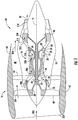
- the fan section 16 includes a plurality of fan blades 40 that are coupled to and that extend radially outwardly from the fan spool 38.
- An annular fan casing or nacelle 42 circumferentially surrounds the fan section 16 and/or at least a portion of the gas turbine engine 14. It should be appreciated by those of ordinary skill in the art that the nacelle 42 may be configured to be supported relative to the gas turbine engine 14 by a plurality of circumferentially-spaced outlet guide vanes 44.
- FIG. 2 provides an enlarged cross sectioned view of the HP turbine 28 portion of the gas turbine engine 14 as shown in FIG. 1 , as may incorporate various embodiments of the present invention.
- the HP turbine 28 includes, in serial flow relationship, a first stage 50 which includes a row 52 of stator vanes 54 (only one shown) axially spaced from a row 56 of turbine rotor blades 58 (only one shown).
- the HP turbine 28 further includes a second stage 60 which includes a row 62 of stator vanes 64 (only one shown) axially spaced from a row 66 of turbine rotor blades 68 (only one shown).
- the turbine rotor blades 58, 68 extend radially outwardly from and are coupled to the HP spool 34 ( FIG. 1 ). As shown in FIG. 2 , the stator vanes 54, 64 and the turbine rotor blades 58, 68 at least partially define a hot gas path 70 for routing combustion gases from the combustion section 26 ( FIG. 1 ) through the HP turbine 28. As shown in FIG. 1 , the rows 52, 62 of the stator vanes 54, 64 are annularly arranged about the HP spool 34 and the rows 56, 66 of the turbine rotor blades 58, 68 are circumferentially spaced around the HP spool 34.
- the HP turbine 28 includes a turbine shroud or shroud seal assembly 72 that forms an annular ring around the row 56 of turbine rotor blades 58 of the first stage 50 with respect to the centerline 12.
- the shroud seal assembly 72 will be described and illustrated surrounding the turbine rotor blades 58 of the first stage 50, the shroud seal assembly 72 as provided herein may be configured to surround any row of turbine rotor blades of the HP turbine 28 or the LP turbine 30 and the invention provided herein is not limited to the first stage 50 of the HP turbine 28 unless specifically stated in the claims.
- the shroud seal assembly 72 includes a shroud seal 74.
- the shroud seal 74 is radially spaced from a blade tip 76 of each of the turbine rotor blades 58.
- a clearance gap is defined between the blade tips 76 and a sealing surface or side 78 of the shroud seal 74. It is generally desirable to minimize the clearance gap between the blade tips 76 and the shroud seals 74, particularly during cruise operation of the turbofan 10 to reduce leakage from the hot gas path 70 through the clearance gap.
- the shroud seal 74 is formed as a continuous, unitary or seamless ring made of a ceramic material and, more particularly, a ceramic matrix composite (CMC) material.
- CMC ceramic matrix composite
- a turbine shroud support ring 90 may be provided to mount the shroud seal support 80.
- air 200 enters an inlet portion 202 of the turbofan 10.
- a first portion of the air 200 as indicated by arrow 204 is directed into the bypass flow passage 48 and a second portion of the air 200 as indicated by arrow 206 enters the inlet 20 of the LP compressor 22.
- the second portion of air 206 is progressively compressed as it is routed from the LP compressor 22 into the HP compressor 24.
- the second portion of the air 206 is further compressed as it is routed through the HP compressor 24, thus providing compressed air as indicated by arrow 208 to the combustion section 26 where it is mixed with fuel and burned to provide combustion gases as indicated by arrow 210.
- shroud seal 74 Use of ceramic, particularly ceramic matrix composite materials to form the shroud seal 74 reduces the amount of cooling air that is normally required to cool the shroud seals 74. Although reduction in cooling flow to cool the shroud seals 74 may enhance overall engine efficiency, the reduction in cooling air flow may have adverse effects on portions of the shroud seal assembly 72 such as the shroud seal support 80 or surrounding stationary hardware that are formed from other materials such as metal alloys that have less favorable thermal properties for use at such elevated temperatures. This may particularly true for hardware such as the shroud seal support 80 that may be potentially exposed or in the line of sight to the combustion gases 210 flowing through the HP turbine 28 and the LP turbine 30.
- the shroud seal 74 is mounted or coupled to the shroud seal support 80.
- the shroud seal 74 includes a leading edge portion 104 that extends towards the forward wall 92 of the shroud seal support 80 and a trailing edge portion 104 that extends towards the aft wall 94 of the shroud seal support 80.
- the leading edge portion 104 of the shroud seal 74 terminates axially between the front side 96 and the back side 98 of the forward wall 92.
- a radial gap 106 is defined between a top surface 108 of the leading edge portion 102 and the radially inner surface 100 of the forward wall.
- a system for thermally shielding a portion of the shroud assembly 72 includes a thermal shield 110 that is disposed along a bottom portion 112 of the forward wall 92.
- the thermal shield 110 may be formed from a ceramic matrix composite material or any material having suitable thermal properties for reducing thermal stresses on the shroud seal support 80 and/or other stationary hardware proximate to the shroud seal assembly 72.
- the thermal shield 110 is generally oriented to face towards or into a flow of the combustion gases 210.
- the thermal shield 110 extends from the front side 96 of the forward wall 92 to the top surface 108 of the shroud seal 74. In one embodiment, the thermal shield 110 is fixedly connected to at least one of the front side 96 of the forward wall 92 and to the top surface 108 of the shroud seal 74. In one embodiment, the thermal shield 110 is fixedly connected to the forward wall 92, but is free to move at an interface between the thermal seal 110 and the top surface 108 of the shroud seal 74, thereby allowing cooling flow to leak or pass through the radial gap. In particular embodiments, the thermal shield 110 at least partially seals the radial gap 106, thus preventing or restricting leakage of the combustion gases 210 onto a backside 114 of the shroud seal 74.
- the thermal shield 110 extends from the bottom portion 112 of the forward wall 92 towards the leading edge portion 102 of the shroud seal 74. In one embodiment, the thermal shield 110 extends from the front side 96 of the forward wall 92 towards the sealing surface 78 of the shroud seal.
- the shroud seal 74 is formed from a ceramic matrix composite as a continuous, unitary or seamless 360 degree ring.
- FIG. 4 provides an enlarged side view that includes a portion of a turbine rotor blade 58, a portion of the stator vane 54 of the first row 52, a portion of the stator vane 64 of the second row 62 and the shroud seal assembly 72 according to various embodiments of the present invention.
- the leading edge portion 102 of the shroud seal 74 terminates axially forward from the front side 96 of the forward wall 92 with respect to axial centerline 12. In this manner, the leading edge portion 102 at least partially defines a system for thermally shielding the forward wall 92 and/or other stationary hardware disposed adjacent to the forward wall 92 from exposure to the combustion gases 210.
- the leading edge portion 102 may extend towards an outer band 116 portion of the stationary vane 54 so as to minimize an axial gap 118 defined between an aft portion 120 of the outer band portion 116 and the leading edge portion 102 of the shroud seal 74 so as to minimize or control leakage of the combustion gases 210 from the hot gap path 70 into a stagnant space or volume 122 defined radially outwardly from the outer band 116 and/or the shroud seal 74.
- the shroud seal 74 is formed from a ceramic matrix composite material and the shroud seal support 80 is formed from a non-ceramic matrix composite material such as sheet metal formed from a metal alloy. In one embodiment, the shroud seal 74 is formed from a ceramic matrix composite as a continuous, unitary or seamless 360 degree ring.
- a thermal shield 124 is disposed along the bottom portion 112 of the front side 96 of the forward wall 92 and is oriented to face towards the flow of the combustion gases 210 and/or towards the stagnant volume 122.
- the thermal shield 124 may be formed from a ceramic matrix composite material or other material such as a metal alloy having suitable thermal properties for the intended purpose of reducing thermal stresses on the non-ceramic or non-ceramic matrix composite materials of the shroud seal assembly 72.
- the thermal shield 124 is connected to the front side 96 of the forward wall 92 and to the top surface 108 of the shroud seal 74. In on embodiment, the thermal shield 124 extends from the bottom portion 112 of the front wall towards the leading edge portion 102 of the shroud seal 74. In particular embodiments, the thermal shield 124 at least partially seals the radial gap 106 defined between the radially inner surface 100 of the forward wall 92 and the top surface 108 of the shroud seal 74. In one embodiment, the thermal shield 124 extends from the front side 96 of the forward wall 92 along a forward surface 126 of the shroud seal 74 and towards the sealing surface 78 of the shroud seal 74.
Landscapes
- Engineering & Computer Science (AREA)
- Mechanical Engineering (AREA)
- General Engineering & Computer Science (AREA)
- Chemical & Material Sciences (AREA)
- Combustion & Propulsion (AREA)
- Turbine Rotor Nozzle Sealing (AREA)
Claims (7)
- System zum thermischen Abschirmen eines Abschnitts einer Gasturbinenverkleidungsanordnung, umfassend:einen Verkleidungsdichtungsträger (80), der aus einem nicht-keramischen Matrix-Verbundwerkstoff gebildet ist und eine Vorderwand (92) aufweist, die axial von einer Hinterwand (94) beabstandet ist, wobei die Vorderwand (92) Folgendes aufweist: eine Vorderseite (96), die axial von der Rückseite (98) beabstandet ist, und eine radial innere Oberfläche (100), die sich axial zwischen der Vorderseite und Rückseite (96, 98) erstreckt, wobei die Vorderwand (92) ferner einen radial inneren Bodenabschnitt (112) aufweist;eine Verkleidungsdichtung (74), die aus einem keramischen Matrix-Verbundwerkstoff gebildet ist und an dem Verkleidungsdichtungsträger (80) angebracht ist, wobei die Verkleidungsdichtung (74) Folgendes aufweist: einen Vorderkantenabschnitt (102), der sich in Richtung der Vorderwand (92) des Verkleidungsdichtungsträgers (80) erstreckt und einen Hinterkantenabschnitt (104), der sich in Richtung der Hinterwand (94) des Verkleidungsdichtungsträgers (80) erstreckt, wobei ein radialer Spalt (106) zwischen einer oberen Oberfläche (108) des Vorderkantenabschnitts (102) der Verkleidungsdichtung und der radial inneren Oberfläche (100) der Vorderwand (92) definiert ist; undeine Wärmeabschirmung (110), die aus einem keramischen Matrix-Verbundwerkstoff gebildet ist, wobei ein erster Endabschnitt an einem distalen Ende der Wärmeabschirmung (110) am radial inneren Bodenabschnitt (112) der Vorderwand (92) angeordnet ist, und ein zweiter Endabschnitt sich am anderen distalen Ende der Wärmeabschirmung (110) zur Verkleidungsdichtung (74) erstreckt, so dass die Wärmeabschirmung (110) den radialen Spalt (106) mindestens teilweise abdichtet.
- System nach Anspruch 1, wobei die Wärmeabschirmung (110) mit der Vorderseite (96) der Vorderwand (92) und mit der oberen Oberfläche (108) der Verkleidungsdichtung (74) verbunden ist.
- System nach Anspruch 1 oder 2, wobei sich die Wärmeabschirmung von dem Bodenabschnitt (112) der Vorderwand (92) in Richtung des Vorderkantenabschnitts (102) der Verkleidungsdichtung (74) erstreckt.
- System nach einem der vorhergehenden Ansprüche, wobei sich die Wärmeabschirmung (110) von der Vorderseite (96) der Vorderwand (92) zu einer Dichtungsfläche (78) der Verkleidungsdichtung (74) erstreckt.
- System nach einem der vorhergehenden Ansprüche, wobei die Verkleidungsdichtung (74) als durchgehender Ring ausgebildet ist.
- System nach einem der vorhergehenden Ansprüchen, wobei der Vorderkantenabschnitt (102) der Verkleidungsdichtung (74) zwischen der Vorderseite (96) und der Rückseite (98) der Vorderwand (92) axial endet.
- Gasturbine (14), umfassend:einen Kompressor (22, 24);eine Brennkammer (26), die dem Kompressor nachgeschaltet angeordnet ist; undeine Turbine (28, 30), die der Brennkammer nachgeschaltet angeordnet ist, wobei die Turbine eine Turbinenverkleidungsanordnung umfasst, die sich umfangsmäßig um eine Reihe von Turbinenrotorschaufeln erstreckt, wobei die Turbine ferner ein System zum thermischen Abschirmen eines Abschnitts der Turbinenverkleidungsanordnung umfasst, wobei das System nach einem der vorhergehenden Ansprüche aufgebaut ist.
Priority Applications (1)
| Application Number | Priority Date | Filing Date | Title |
|---|---|---|---|
| EP19173649.5A EP3543471B1 (de) | 2015-05-11 | 2016-03-08 | System zur thermischen abschirmung eines abschnitts einer gasturbinenmantelanordnung |
Applications Claiming Priority (1)
| Application Number | Priority Date | Filing Date | Title |
|---|---|---|---|
| US14/708,385 US10233844B2 (en) | 2015-05-11 | 2015-05-11 | System for thermally shielding a portion of a gas turbine shroud assembly |
Related Child Applications (2)
| Application Number | Title | Priority Date | Filing Date |
|---|---|---|---|
| EP19173649.5A Division-Into EP3543471B1 (de) | 2015-05-11 | 2016-03-08 | System zur thermischen abschirmung eines abschnitts einer gasturbinenmantelanordnung |
| EP19173649.5A Division EP3543471B1 (de) | 2015-05-11 | 2016-03-08 | System zur thermischen abschirmung eines abschnitts einer gasturbinenmantelanordnung |
Publications (2)
| Publication Number | Publication Date |
|---|---|
| EP3095958A1 EP3095958A1 (de) | 2016-11-23 |
| EP3095958B1 true EP3095958B1 (de) | 2019-06-19 |
Family
ID=55486580
Family Applications (2)
| Application Number | Title | Priority Date | Filing Date |
|---|---|---|---|
| EP19173649.5A Active EP3543471B1 (de) | 2015-05-11 | 2016-03-08 | System zur thermischen abschirmung eines abschnitts einer gasturbinenmantelanordnung |
| EP16159096.3A Active EP3095958B1 (de) | 2015-05-11 | 2016-03-08 | System zur thermischen abschirmung eines abschnitts eines gasturbinenmantelanordnung |
Family Applications Before (1)
| Application Number | Title | Priority Date | Filing Date |
|---|---|---|---|
| EP19173649.5A Active EP3543471B1 (de) | 2015-05-11 | 2016-03-08 | System zur thermischen abschirmung eines abschnitts einer gasturbinenmantelanordnung |
Country Status (5)
| Country | Link |
|---|---|
| US (1) | US10233844B2 (de) |
| EP (2) | EP3543471B1 (de) |
| JP (1) | JP6263212B2 (de) |
| CN (1) | CN106150568B (de) |
| CA (1) | CA2922517C (de) |
Families Citing this family (9)
| Publication number | Priority date | Publication date | Assignee | Title |
|---|---|---|---|---|
| US10428689B2 (en) * | 2017-05-17 | 2019-10-01 | Rolls-Royce Deutschland Ltd & Co Kg | Heat shield for a gas turbine engine |
| EP3421727B1 (de) * | 2017-06-30 | 2020-01-29 | Ansaldo Energia Switzerland AG | Gasturbine mit einem turbinenschaufelträger |
| US10858953B2 (en) | 2017-09-01 | 2020-12-08 | Rolls-Royce Deutschland Ltd & Co Kg | Turbine casing heat shield in a gas turbine engine |
| EP3450703B1 (de) * | 2017-09-01 | 2020-05-20 | Rolls-Royce Deutschland Ltd & Co KG | Turbinengehäusehitzeschild für turboluftstrahltriebwerke |
| US11021990B2 (en) * | 2018-12-19 | 2021-06-01 | General Electric Company | Shroud sealing for a gas turbine engine |
| US10968764B2 (en) * | 2019-05-31 | 2021-04-06 | Rolls-Royce Corporation | Ceramic matrix composite hanger heat shield |
| FR3100838B1 (fr) | 2019-09-13 | 2021-10-01 | Safran Aircraft Engines | Anneau d’etancheite de turbomachine |
| US11131215B2 (en) | 2019-11-19 | 2021-09-28 | Rolls-Royce North American Technologies Inc. | Turbine shroud cartridge assembly with sealing features |
| US11092027B2 (en) | 2019-11-19 | 2021-08-17 | Rolls-Royce North American Technologies Inc. | Turbine shroud assembly with sheet-metal sealing features |
Family Cites Families (21)
| Publication number | Priority date | Publication date | Assignee | Title |
|---|---|---|---|---|
| US4087199A (en) * | 1976-11-22 | 1978-05-02 | General Electric Company | Ceramic turbine shroud assembly |
| US4573866A (en) | 1983-05-02 | 1986-03-04 | United Technologies Corporation | Sealed shroud for rotating body |
| US5332358A (en) | 1993-03-01 | 1994-07-26 | General Electric Company | Uncoupled seal support assembly |
| US5374161A (en) | 1993-12-13 | 1994-12-20 | United Technologies Corporation | Blade outer air seal cooling enhanced with inter-segment film slot |
| DE19915049A1 (de) | 1999-04-01 | 2000-10-05 | Abb Alstom Power Ch Ag | Hitzeschild für eine Gasturbine |
| DE10209295B4 (de) | 2002-03-01 | 2010-12-09 | Alstom Technology Ltd. | Spaltdichtung bei einer Gasturbine |
| US6758653B2 (en) | 2002-09-09 | 2004-07-06 | Siemens Westinghouse Power Corporation | Ceramic matrix composite component for a gas turbine engine |
| US7186078B2 (en) * | 2003-07-04 | 2007-03-06 | Ishikawajima-Harima Heavy Industries Co., Ltd. | Turbine shroud segment |
| US6997673B2 (en) | 2003-12-11 | 2006-02-14 | Honeywell International, Inc. | Gas turbine high temperature turbine blade outer air seal assembly |
| US7044709B2 (en) | 2004-01-15 | 2006-05-16 | General Electric Company | Methods and apparatus for coupling ceramic matrix composite turbine components |
| JP4495481B2 (ja) * | 2004-02-18 | 2010-07-07 | イーグル・エンジニアリング・エアロスペース株式会社 | シール装置 |
| US7217089B2 (en) | 2005-01-14 | 2007-05-15 | Pratt & Whitney Canada Corp. | Gas turbine engine shroud sealing arrangement |
| US7811054B2 (en) | 2007-05-30 | 2010-10-12 | General Electric Company | Shroud configuration having sloped seal |
| SI2173974T1 (sl) | 2007-06-28 | 2012-03-30 | Alstom Technology Ltd | Segment toplotnega ščita za stator plinske turbine |
| US7946801B2 (en) | 2007-12-27 | 2011-05-24 | General Electric Company | Multi-source gas turbine cooling |
| US8651497B2 (en) | 2011-06-17 | 2014-02-18 | United Technologies Corporation | Winged W-seal |
| US9726043B2 (en) | 2011-12-15 | 2017-08-08 | General Electric Company | Mounting apparatus for low-ductility turbine shroud |
| US20130210299A1 (en) | 2012-02-09 | 2013-08-15 | General Electric Company | Reinforced coatings and methods of making the same |
| US20160040547A1 (en) | 2013-04-12 | 2016-02-11 | United Technologies Corporation | Blade outer air seal with secondary air sealing |
| WO2015047478A2 (en) * | 2013-07-23 | 2015-04-02 | United Technologies Corporation | Radial position control of case support structure with splined connection |
| CA2915246A1 (en) * | 2014-12-23 | 2016-06-23 | Rolls-Royce Corporation | Turbine shroud |
-
2015
- 2015-05-11 US US14/708,385 patent/US10233844B2/en active Active
-
2016
- 2016-03-03 CA CA2922517A patent/CA2922517C/en active Active
- 2016-03-07 JP JP2016042942A patent/JP6263212B2/ja active Active
- 2016-03-08 EP EP19173649.5A patent/EP3543471B1/de active Active
- 2016-03-08 EP EP16159096.3A patent/EP3095958B1/de active Active
- 2016-03-11 CN CN201610138289.2A patent/CN106150568B/zh active Active
Non-Patent Citations (1)
| Title |
|---|
| None * |
Also Published As
| Publication number | Publication date |
|---|---|
| CA2922517C (en) | 2019-11-12 |
| CN106150568A (zh) | 2016-11-23 |
| JP6263212B2 (ja) | 2018-01-17 |
| US20160333788A1 (en) | 2016-11-17 |
| EP3095958A1 (de) | 2016-11-23 |
| EP3543471A1 (de) | 2019-09-25 |
| JP2016211538A (ja) | 2016-12-15 |
| US10233844B2 (en) | 2019-03-19 |
| CA2922517A1 (en) | 2016-11-11 |
| EP3543471B1 (de) | 2021-01-13 |
| CN106150568B (zh) | 2018-04-06 |
Similar Documents
| Publication | Publication Date | Title |
|---|---|---|
| EP3095958B1 (de) | System zur thermischen abschirmung eines abschnitts eines gasturbinenmantelanordnung | |
| US10400627B2 (en) | System for cooling a turbine engine | |
| US11021990B2 (en) | Shroud sealing for a gas turbine engine | |
| US10301960B2 (en) | Shroud assembly for gas turbine engine | |
| US10876407B2 (en) | Thermal structure for outer diameter mounted turbine blades | |
| US10132186B2 (en) | System and method for supporting a turbine shroud | |
| CN105986847B (zh) | 用于冷却涡轮护罩的系统 | |
| EP2938839B1 (de) | Aussendichtung für eine schaufel mit stufenfalzstruktur | |
| EP3090140B1 (de) | Aussendichtung für eine turbinenschaufel mit sekundärluftabdichtung | |
| US20180230839A1 (en) | Turbine engine shroud assembly | |
| EP3093448A1 (de) | Wärmeisolierte turbinenmantelanordnung | |
| JP2017053350A (ja) | セラミックマトリックス複合材料シュラウドを軸方向に保持するための高度な静止シール冷却断面 | |
| US11149692B2 (en) | Deflection mitigation structure for combustion system |
Legal Events
| Date | Code | Title | Description |
|---|---|---|---|
| PUAI | Public reference made under article 153(3) epc to a published international application that has entered the european phase |
Free format text: ORIGINAL CODE: 0009012 |
|
| AK | Designated contracting states |
Kind code of ref document: A1 Designated state(s): AL AT BE BG CH CY CZ DE DK EE ES FI FR GB GR HR HU IE IS IT LI LT LU LV MC MK MT NL NO PL PT RO RS SE SI SK SM TR |
|
| AX | Request for extension of the european patent |
Extension state: BA ME |
|
| STAA | Information on the status of an ep patent application or granted ep patent |
Free format text: STATUS: REQUEST FOR EXAMINATION WAS MADE |
|
| 17P | Request for examination filed |
Effective date: 20170523 |
|
| RBV | Designated contracting states (corrected) |
Designated state(s): AL AT BE BG CH CY CZ DE DK EE ES FI FR GB GR HR HU IE IS IT LI LT LU LV MC MK MT NL NO PL PT RO RS SE SI SK SM TR |
|
| GRAP | Despatch of communication of intention to grant a patent |
Free format text: ORIGINAL CODE: EPIDOSNIGR1 |
|
| STAA | Information on the status of an ep patent application or granted ep patent |
Free format text: STATUS: GRANT OF PATENT IS INTENDED |
|
| INTG | Intention to grant announced |
Effective date: 20190109 |
|
| GRAS | Grant fee paid |
Free format text: ORIGINAL CODE: EPIDOSNIGR3 |
|
| GRAA | (expected) grant |
Free format text: ORIGINAL CODE: 0009210 |
|
| STAA | Information on the status of an ep patent application or granted ep patent |
Free format text: STATUS: THE PATENT HAS BEEN GRANTED |
|
| AK | Designated contracting states |
Kind code of ref document: B1 Designated state(s): AL AT BE BG CH CY CZ DE DK EE ES FI FR GB GR HR HU IE IS IT LI LT LU LV MC MK MT NL NO PL PT RO RS SE SI SK SM TR |
|
| REG | Reference to a national code |
Ref country code: GB Ref legal event code: FG4D |
|
| REG | Reference to a national code |
Ref country code: CH Ref legal event code: EP |
|
| REG | Reference to a national code |
Ref country code: IE Ref legal event code: FG4D |
|
| REG | Reference to a national code |
Ref country code: AT Ref legal event code: REF Ref document number: 1145753 Country of ref document: AT Kind code of ref document: T Effective date: 20190715 |
|
| REG | Reference to a national code |
Ref country code: DE Ref legal event code: R096 Ref document number: 602016015381 Country of ref document: DE |
|
| REG | Reference to a national code |
Ref country code: NL Ref legal event code: MP Effective date: 20190619 |
|
| PG25 | Lapsed in a contracting state [announced via postgrant information from national office to epo] |
Ref country code: HR Free format text: LAPSE BECAUSE OF FAILURE TO SUBMIT A TRANSLATION OF THE DESCRIPTION OR TO PAY THE FEE WITHIN THE PRESCRIBED TIME-LIMIT Effective date: 20190619 Ref country code: LT Free format text: LAPSE BECAUSE OF FAILURE TO SUBMIT A TRANSLATION OF THE DESCRIPTION OR TO PAY THE FEE WITHIN THE PRESCRIBED TIME-LIMIT Effective date: 20190619 Ref country code: SE Free format text: LAPSE BECAUSE OF FAILURE TO SUBMIT A TRANSLATION OF THE DESCRIPTION OR TO PAY THE FEE WITHIN THE PRESCRIBED TIME-LIMIT Effective date: 20190619 Ref country code: NO Free format text: LAPSE BECAUSE OF FAILURE TO SUBMIT A TRANSLATION OF THE DESCRIPTION OR TO PAY THE FEE WITHIN THE PRESCRIBED TIME-LIMIT Effective date: 20190919 Ref country code: AL Free format text: LAPSE BECAUSE OF FAILURE TO SUBMIT A TRANSLATION OF THE DESCRIPTION OR TO PAY THE FEE WITHIN THE PRESCRIBED TIME-LIMIT Effective date: 20190619 Ref country code: FI Free format text: LAPSE BECAUSE OF FAILURE TO SUBMIT A TRANSLATION OF THE DESCRIPTION OR TO PAY THE FEE WITHIN THE PRESCRIBED TIME-LIMIT Effective date: 20190619 |
|
| REG | Reference to a national code |
Ref country code: LT Ref legal event code: MG4D |
|
| PG25 | Lapsed in a contracting state [announced via postgrant information from national office to epo] |
Ref country code: BG Free format text: LAPSE BECAUSE OF FAILURE TO SUBMIT A TRANSLATION OF THE DESCRIPTION OR TO PAY THE FEE WITHIN THE PRESCRIBED TIME-LIMIT Effective date: 20190919 Ref country code: RS Free format text: LAPSE BECAUSE OF FAILURE TO SUBMIT A TRANSLATION OF THE DESCRIPTION OR TO PAY THE FEE WITHIN THE PRESCRIBED TIME-LIMIT Effective date: 20190619 Ref country code: LV Free format text: LAPSE BECAUSE OF FAILURE TO SUBMIT A TRANSLATION OF THE DESCRIPTION OR TO PAY THE FEE WITHIN THE PRESCRIBED TIME-LIMIT Effective date: 20190619 Ref country code: GR Free format text: LAPSE BECAUSE OF FAILURE TO SUBMIT A TRANSLATION OF THE DESCRIPTION OR TO PAY THE FEE WITHIN THE PRESCRIBED TIME-LIMIT Effective date: 20190920 |
|
| REG | Reference to a national code |
Ref country code: AT Ref legal event code: MK05 Ref document number: 1145753 Country of ref document: AT Kind code of ref document: T Effective date: 20190619 |
|
| PG25 | Lapsed in a contracting state [announced via postgrant information from national office to epo] |
Ref country code: EE Free format text: LAPSE BECAUSE OF FAILURE TO SUBMIT A TRANSLATION OF THE DESCRIPTION OR TO PAY THE FEE WITHIN THE PRESCRIBED TIME-LIMIT Effective date: 20190619 Ref country code: PT Free format text: LAPSE BECAUSE OF FAILURE TO SUBMIT A TRANSLATION OF THE DESCRIPTION OR TO PAY THE FEE WITHIN THE PRESCRIBED TIME-LIMIT Effective date: 20191021 Ref country code: SK Free format text: LAPSE BECAUSE OF FAILURE TO SUBMIT A TRANSLATION OF THE DESCRIPTION OR TO PAY THE FEE WITHIN THE PRESCRIBED TIME-LIMIT Effective date: 20190619 Ref country code: CZ Free format text: LAPSE BECAUSE OF FAILURE TO SUBMIT A TRANSLATION OF THE DESCRIPTION OR TO PAY THE FEE WITHIN THE PRESCRIBED TIME-LIMIT Effective date: 20190619 Ref country code: RO Free format text: LAPSE BECAUSE OF FAILURE TO SUBMIT A TRANSLATION OF THE DESCRIPTION OR TO PAY THE FEE WITHIN THE PRESCRIBED TIME-LIMIT Effective date: 20190619 Ref country code: AT Free format text: LAPSE BECAUSE OF FAILURE TO SUBMIT A TRANSLATION OF THE DESCRIPTION OR TO PAY THE FEE WITHIN THE PRESCRIBED TIME-LIMIT Effective date: 20190619 Ref country code: NL Free format text: LAPSE BECAUSE OF FAILURE TO SUBMIT A TRANSLATION OF THE DESCRIPTION OR TO PAY THE FEE WITHIN THE PRESCRIBED TIME-LIMIT Effective date: 20190619 |
|
| PG25 | Lapsed in a contracting state [announced via postgrant information from national office to epo] |
Ref country code: ES Free format text: LAPSE BECAUSE OF FAILURE TO SUBMIT A TRANSLATION OF THE DESCRIPTION OR TO PAY THE FEE WITHIN THE PRESCRIBED TIME-LIMIT Effective date: 20190619 Ref country code: SM Free format text: LAPSE BECAUSE OF FAILURE TO SUBMIT A TRANSLATION OF THE DESCRIPTION OR TO PAY THE FEE WITHIN THE PRESCRIBED TIME-LIMIT Effective date: 20190619 Ref country code: IS Free format text: LAPSE BECAUSE OF FAILURE TO SUBMIT A TRANSLATION OF THE DESCRIPTION OR TO PAY THE FEE WITHIN THE PRESCRIBED TIME-LIMIT Effective date: 20191019 Ref country code: IT Free format text: LAPSE BECAUSE OF FAILURE TO SUBMIT A TRANSLATION OF THE DESCRIPTION OR TO PAY THE FEE WITHIN THE PRESCRIBED TIME-LIMIT Effective date: 20190619 |
|
| PG25 | Lapsed in a contracting state [announced via postgrant information from national office to epo] |
Ref country code: TR Free format text: LAPSE BECAUSE OF FAILURE TO SUBMIT A TRANSLATION OF THE DESCRIPTION OR TO PAY THE FEE WITHIN THE PRESCRIBED TIME-LIMIT Effective date: 20190619 |
|
| PG25 | Lapsed in a contracting state [announced via postgrant information from national office to epo] |
Ref country code: DK Free format text: LAPSE BECAUSE OF FAILURE TO SUBMIT A TRANSLATION OF THE DESCRIPTION OR TO PAY THE FEE WITHIN THE PRESCRIBED TIME-LIMIT Effective date: 20190619 Ref country code: PL Free format text: LAPSE BECAUSE OF FAILURE TO SUBMIT A TRANSLATION OF THE DESCRIPTION OR TO PAY THE FEE WITHIN THE PRESCRIBED TIME-LIMIT Effective date: 20190619 |
|
| PG25 | Lapsed in a contracting state [announced via postgrant information from national office to epo] |
Ref country code: IS Free format text: LAPSE BECAUSE OF FAILURE TO SUBMIT A TRANSLATION OF THE DESCRIPTION OR TO PAY THE FEE WITHIN THE PRESCRIBED TIME-LIMIT Effective date: 20200224 |
|
| REG | Reference to a national code |
Ref country code: DE Ref legal event code: R097 Ref document number: 602016015381 Country of ref document: DE |
|
| PLBE | No opposition filed within time limit |
Free format text: ORIGINAL CODE: 0009261 |
|
| STAA | Information on the status of an ep patent application or granted ep patent |
Free format text: STATUS: NO OPPOSITION FILED WITHIN TIME LIMIT |
|
| PG2D | Information on lapse in contracting state deleted |
Ref country code: IS |
|
| 26N | No opposition filed |
Effective date: 20200603 |
|
| PG25 | Lapsed in a contracting state [announced via postgrant information from national office to epo] |
Ref country code: SI Free format text: LAPSE BECAUSE OF FAILURE TO SUBMIT A TRANSLATION OF THE DESCRIPTION OR TO PAY THE FEE WITHIN THE PRESCRIBED TIME-LIMIT Effective date: 20190619 |
|
| PG25 | Lapsed in a contracting state [announced via postgrant information from national office to epo] |
Ref country code: MC Free format text: LAPSE BECAUSE OF FAILURE TO SUBMIT A TRANSLATION OF THE DESCRIPTION OR TO PAY THE FEE WITHIN THE PRESCRIBED TIME-LIMIT Effective date: 20190619 |
|
| REG | Reference to a national code |
Ref country code: CH Ref legal event code: PL |
|
| REG | Reference to a national code |
Ref country code: BE Ref legal event code: MM Effective date: 20200331 |
|
| PG25 | Lapsed in a contracting state [announced via postgrant information from national office to epo] |
Ref country code: LU Free format text: LAPSE BECAUSE OF NON-PAYMENT OF DUE FEES Effective date: 20200308 |
|
| PG25 | Lapsed in a contracting state [announced via postgrant information from national office to epo] |
Ref country code: IE Free format text: LAPSE BECAUSE OF NON-PAYMENT OF DUE FEES Effective date: 20200308 Ref country code: CH Free format text: LAPSE BECAUSE OF NON-PAYMENT OF DUE FEES Effective date: 20200331 Ref country code: LI Free format text: LAPSE BECAUSE OF NON-PAYMENT OF DUE FEES Effective date: 20200331 |
|
| PG25 | Lapsed in a contracting state [announced via postgrant information from national office to epo] |
Ref country code: BE Free format text: LAPSE BECAUSE OF NON-PAYMENT OF DUE FEES Effective date: 20200331 |
|
| PG25 | Lapsed in a contracting state [announced via postgrant information from national office to epo] |
Ref country code: MT Free format text: LAPSE BECAUSE OF FAILURE TO SUBMIT A TRANSLATION OF THE DESCRIPTION OR TO PAY THE FEE WITHIN THE PRESCRIBED TIME-LIMIT Effective date: 20190619 Ref country code: CY Free format text: LAPSE BECAUSE OF FAILURE TO SUBMIT A TRANSLATION OF THE DESCRIPTION OR TO PAY THE FEE WITHIN THE PRESCRIBED TIME-LIMIT Effective date: 20190619 |
|
| PG25 | Lapsed in a contracting state [announced via postgrant information from national office to epo] |
Ref country code: MK Free format text: LAPSE BECAUSE OF FAILURE TO SUBMIT A TRANSLATION OF THE DESCRIPTION OR TO PAY THE FEE WITHIN THE PRESCRIBED TIME-LIMIT Effective date: 20190619 |
|
| P01 | Opt-out of the competence of the unified patent court (upc) registered |
Effective date: 20230414 |
|
| PGFP | Annual fee paid to national office [announced via postgrant information from national office to epo] |
Ref country code: GB Payment date: 20260220 Year of fee payment: 11 |
|
| PGFP | Annual fee paid to national office [announced via postgrant information from national office to epo] |
Ref country code: DE Payment date: 20260219 Year of fee payment: 11 |
|
| PGFP | Annual fee paid to national office [announced via postgrant information from national office to epo] |
Ref country code: FR Payment date: 20260220 Year of fee payment: 11 |