EP3095964A1 - Plaque de capture pré-biaisée - Google Patents
Plaque de capture pré-biaisée Download PDFInfo
- Publication number
- EP3095964A1 EP3095964A1 EP16170483.8A EP16170483A EP3095964A1 EP 3095964 A1 EP3095964 A1 EP 3095964A1 EP 16170483 A EP16170483 A EP 16170483A EP 3095964 A1 EP3095964 A1 EP 3095964A1
- Authority
- EP
- European Patent Office
- Prior art keywords
- frame case
- axis
- conduit
- frame
- recited
- Prior art date
- Legal status (The legal status is an assumption and is not a legal conclusion. Google has not performed a legal analysis and makes no representation as to the accuracy of the status listed.)
- Granted
Links
Images




Classifications
-
- F—MECHANICAL ENGINEERING; LIGHTING; HEATING; WEAPONS; BLASTING
- F02—COMBUSTION ENGINES; HOT-GAS OR COMBUSTION-PRODUCT ENGINE PLANTS
- F02C—GAS-TURBINE PLANTS; AIR INTAKES FOR JET-PROPULSION PLANTS; CONTROLLING FUEL SUPPLY IN AIR-BREATHING JET-PROPULSION PLANTS
- F02C7/00—Features, components parts, details or accessories, not provided for in, or of interest apart form groups F02C1/00 - F02C6/00; Air intakes for jet-propulsion plants
- F02C7/06—Arrangements of bearings; Lubricating
-
- F—MECHANICAL ENGINEERING; LIGHTING; HEATING; WEAPONS; BLASTING
- F01—MACHINES OR ENGINES IN GENERAL; ENGINE PLANTS IN GENERAL; STEAM ENGINES
- F01D—NON-POSITIVE DISPLACEMENT MACHINES OR ENGINES, e.g. STEAM TURBINES
- F01D9/00—Stators
- F01D9/06—Fluid supply conduits to nozzles or the like
- F01D9/065—Fluid supply or removal conduits traversing the working fluid flow, e.g. for lubrication-, cooling-, or sealing fluids
-
- F—MECHANICAL ENGINEERING; LIGHTING; HEATING; WEAPONS; BLASTING
- F02—COMBUSTION ENGINES; HOT-GAS OR COMBUSTION-PRODUCT ENGINE PLANTS
- F02C—GAS-TURBINE PLANTS; AIR INTAKES FOR JET-PROPULSION PLANTS; CONTROLLING FUEL SUPPLY IN AIR-BREATHING JET-PROPULSION PLANTS
- F02C3/00—Gas-turbine plants characterised by the use of combustion products as the working fluid
- F02C3/04—Gas-turbine plants characterised by the use of combustion products as the working fluid having a turbine driving a compressor
- F02C3/06—Gas-turbine plants characterised by the use of combustion products as the working fluid having a turbine driving a compressor the compressor comprising only axial stages
-
- F—MECHANICAL ENGINEERING; LIGHTING; HEATING; WEAPONS; BLASTING
- F02—COMBUSTION ENGINES; HOT-GAS OR COMBUSTION-PRODUCT ENGINE PLANTS
- F02C—GAS-TURBINE PLANTS; AIR INTAKES FOR JET-PROPULSION PLANTS; CONTROLLING FUEL SUPPLY IN AIR-BREATHING JET-PROPULSION PLANTS
- F02C7/00—Features, components parts, details or accessories, not provided for in, or of interest apart form groups F02C1/00 - F02C6/00; Air intakes for jet-propulsion plants
- F02C7/20—Mounting or supporting of plant; Accommodating heat expansion or creep
-
- F—MECHANICAL ENGINEERING; LIGHTING; HEATING; WEAPONS; BLASTING
- F05—INDEXING SCHEMES RELATING TO ENGINES OR PUMPS IN VARIOUS SUBCLASSES OF CLASSES F01-F04
- F05D—INDEXING SCHEME FOR ASPECTS RELATING TO NON-POSITIVE-DISPLACEMENT MACHINES OR ENGINES, GAS-TURBINES OR JET-PROPULSION PLANTS
- F05D2220/00—Application
- F05D2220/30—Application in turbines
- F05D2220/32—Application in turbines in gas turbines
-
- F—MECHANICAL ENGINEERING; LIGHTING; HEATING; WEAPONS; BLASTING
- F05—INDEXING SCHEMES RELATING TO ENGINES OR PUMPS IN VARIOUS SUBCLASSES OF CLASSES F01-F04
- F05D—INDEXING SCHEME FOR ASPECTS RELATING TO NON-POSITIVE-DISPLACEMENT MACHINES OR ENGINES, GAS-TURBINES OR JET-PROPULSION PLANTS
- F05D2230/00—Manufacture
- F05D2230/60—Assembly methods
-
- Y—GENERAL TAGGING OF NEW TECHNOLOGICAL DEVELOPMENTS; GENERAL TAGGING OF CROSS-SECTIONAL TECHNOLOGIES SPANNING OVER SEVERAL SECTIONS OF THE IPC; TECHNICAL SUBJECTS COVERED BY FORMER USPC CROSS-REFERENCE ART COLLECTIONS [XRACs] AND DIGESTS
- Y02—TECHNOLOGIES OR APPLICATIONS FOR MITIGATION OR ADAPTATION AGAINST CLIMATE CHANGE
- Y02T—CLIMATE CHANGE MITIGATION TECHNOLOGIES RELATED TO TRANSPORTATION
- Y02T50/00—Aeronautics or air transport
- Y02T50/60—Efficient propulsion technologies, e.g. for aircraft
Definitions
- This disclosure relates to coupling a component of a gas turbine engine, and more particularly to a coupling arrangement for a turbine frame.
- a gas turbine engine typically includes a fan section, a compressor section, a combustor section, and a turbine section. Air entering the compressor section is compressed and delivered into the combustion section where it is mixed with fuel and ignited to generate a high-speed exhaust gas flow. The high-speed exhaust gas flow expands through the turbine section to drive the compressor and the fan section.
- Some turbine engines include a mid-turbine frame configured to transfer loads between a bearing compartment and other portions of the engine static structure.
- the mid-turbine frame may include one or more service lines for communicating fluid with the bearing compartment.
- a coupling arrangement for a gas turbine engine includes a conduit between a first frame case defining a frame axis and a second frame case.
- a flange is coupled to the conduit defining a first axis and abuts the first frame case.
- a capture plate coupled to the conduit defines a second axis and abuts the second frame case. The first axis is offset relative to the second axis in an axial direction relative to the frame axis.
- the first axis is offset relative to the second axis by a predetermined distance in the axial direction.
- the first axis is offset relative to the second axis in a circumferential direction relative to the frame axis.
- the flange defines a bore extending along the first axis and coupled to the conduit.
- the first axis is located at a first axial position
- the second axis is located at a second, different axial position relative to the frame axis.
- the conduit is fixedly attached to the flange and is pivotably coupled to the capture plate.
- the capture plate has a bore extending along the second axis, and the conduit includes a fitting configured to pivotably engage surfaces of the bore.
- the capture plate includes a main body defining the bore, a collar portion extending from the main body and configured to abut the second frame case when in an installed position, and an interference member configured to selectively engage the second frame case such that the collar portion is spaced apart from the second frame case.
- the main body is at least partially received in the second frame case when the interference member is spaced apart from the second frame case.
- the collar portion defines an aperture configured to receive a fastener, and the aperture is positioned relative to the second axis such that the first axis is offset relative to the second axis by a predetermined distance.
- the conduit is configured to communicate fluid with a bearing compartment.
- a gas turbine engine includes a mid-turbine frame between a first turbine and a second turbine.
- the mid-turbine frame includes a plurality of conduits extending between a first frame case and a second frame case, a plurality of flanges each defining a first axis and connecting one of the plurality of conduits to the first frame case, and a plurality of capture plates each defining a second axis and connecting one of the plurality of conduits to the second frame case such that each of the second axes is offset relative to a corresponding one of the first axes.
- At least one of the plurality of conduits is configured to communicate fluid with a bearing compartment.
- the first frame case is an inner frame case
- the second frame case is an outer frame case surrounding at least a portion of the first frame case.
- the second frame case is an inner frame case
- the first frame case is an outer frame case surrounding at least a portion of the second frame case.
- a method of designing a gas turbine engine includes a) coupling a conduit to a first frame case at a first axial position; and b) coupling the conduit to a second frame case at a second axial position such that the conduit is loaded in a first direction.
- a further embodiment of the foregoing embodiment includes applying a load to the first frame case in a second, different direction to reduce a distance between the first axial position and the second axial position.
- the load in the first direction is less than or equal to the load in the second direction.
- step b) includes determining the second axial position based upon thermal growth of the first frame case relative to the second frame case when in a first operating condition.
- a further embodiment of any of the foregoing embodiments includes pivotably coupling the conduit to the second frame case.
- the conduit is configured to communicate fluid with a bearing compartment.
- FIG. 1 schematically illustrates a gas turbine engine 20.
- the gas turbine engine 20 is disclosed herein as a two-spool turbofan that generally incorporates a fan section 22, a compressor section 24, a combustor section 26 and a turbine section 28.
- Alternative engines might include an augmentor section (not shown) among other systems or features.
- the fan section 22 drives air along a bypass flow path B in a bypass duct defined within a nacelle 15, while the compressor section 24 drives air along a core flow path C for compression and communication into the combustor section 26 then expansion through the turbine section 28.
- the exemplary engine 20 generally includes a low speed spool 30 and a high speed spool 32 mounted for rotation about an engine central longitudinal axis A relative to an engine static structure 36 via several bearing systems 38. It should be understood that various bearing systems 38 at various locations may alternatively or additionally be provided, and the location of bearing systems 38 may be varied as appropriate to the application.
- the low speed spool 30 generally includes an inner shaft 40 that interconnects a fan 42, a first (or low) pressure compressor 44 and a first (or low) pressure turbine 46.
- the inner shaft 40 is connected to the fan 42 through a speed change mechanism, which in exemplary gas turbine engine 20 is illustrated as a geared architecture 48 to drive the fan 42 at a lower speed than the low speed spool 30.
- the high speed spool 32 includes an outer shaft 50 that interconnects a second (or high) pressure compressor 52 and a second (or high) pressure turbine 54.
- a combustor 56 is arranged in exemplary gas turbine 20 between the high pressure compressor 52 and the high pressure turbine 54.
- a mid-turbine frame 57 of the engine static structure 36 is arranged generally between the high pressure turbine 54 and the low pressure turbine 46.
- the mid-turbine frame 57 further supports bearing systems 38 in the turbine section 28.
- the inner shaft 40 and the outer shaft 50 are concentric and rotate via bearing systems 38 about the engine central longitudinal axis A which is collinear with their longitudinal axes.
- the core airflow is compressed by the low pressure compressor 44 then the high pressure compressor 52, mixed and burned with fuel in the combustor 56, then expanded over the high pressure turbine 54 and low pressure turbine 46.
- the mid-turbine frame 57 includes airfoils 59 which are in the core airflow path C.
- the turbines 46, 54 rotationally drive the respective low speed spool 30 and high speed spool 32 in response to the expansion.
- gear system 48 may be located aft of combustor section 26 or even aft of turbine section 28, and fan section 22 may be positioned forward or aft of the location of gear system 48.
- the engine 20 in one example is a high-bypass geared aircraft engine.
- the engine 20 bypass ratio is greater than about six, with an example embodiment being greater than about ten
- the geared architecture 48 is an epicyclic gear train, such as a planetary gear system or other gear system, with a gear reduction ratio of greater than about 2.3 and the low pressure turbine 46 has a pressure ratio that is greater than about five.
- the engine 20 bypass ratio is greater than about ten
- the fan diameter is significantly larger than that of the low pressure compressor 44
- the low pressure turbine 46 has a pressure ratio that is greater than about five.
- Low pressure turbine 46 pressure ratio is pressure measured prior to inlet of low pressure turbine 46 as related to the pressure at the outlet of the low pressure turbine 46 prior to an exhaust nozzle.
- the geared architecture 48 may be an epicycle gear train, such as a planetary gear system or other gear system, with a gear reduction ratio of greater than about 2.3. It should be understood, however, that the above parameters are only exemplary of one embodiment of a geared architecture engine and that the present invention is applicable to other gas turbine engines including direct drive turbofans.
- the fan section 22 of the engine 20 is designed for a particular flight condition -- typically cruise at about 0.8 Mach and about 35,000 feet (10,668 m).
- 'TSFC' Thrust Specific Fuel Consumption
- Low fan pressure ratio is the pressure ratio across the fan blade alone, without a Fan Exit Guide Vane (“FEGV”) system.
- the low fan pressure ratio as disclosed herein according to one non-limiting embodiment is less than about 1.45.
- the "Low corrected fan tip speed" as disclosed herein according to one non-limiting embodiment is less than about 1150 ft / second (351 m/s).
- FIG 2 is a schematic perspective view of the mid-turbine frame 57.
- the mid-turbine frame 57 includes an outer frame case 62 and an inner frame case 64 coaxially arranged about a frame axis B.
- the frame axis B can be aligned with the engine axis A (shown in Figures 1 and 3A ).
- the mid-turbine frame 57 is arranged axially between the low pressure turbine 46 (or first turbine) and the high pressure turbine 54 (or second turbine) shown in Figure 1 .
- the inner frame case 64 extends axially between a forwardmost portion 58A and an aftmost portion 58B.
- One or more spokes or tie rods 66 are distributed around a circumference of the inner frame case 64 and extend radially between an inner diameter 61 of the outer frame case 62 and an outer diameter 63 of the inner frame case 64 to provide structural support between the outer and inner frame cases 62, 64.
- the axial and radial directions are in relation to the frame axis B unless stated otherwise.
- the inner frame case 64 supports the rotor assembly via the bearing system 38 (shown in Figure 1 ), and distributes forces from the inner frame case 64 to the outer frame case 62 via the spokes 66.
- the outer frame case 62 is configured to transfer loads from the inner frame case 64 to other portions of the engine static structure 36 (shown in Figure 1 ).
- one or more spokes 66 A define cooling passage(s) 55 (shown schematically in dashed line) to communicate cooling airflow from a coolant source 67 to the bearing system 38 or to a rotor assembly of the turbine section 28.
- Coolant sources 67 can include bleed air from an upstream stage of the compressor section 24, bypass air, or a secondary cooling system aboard the aircraft, for example.
- One or more service lines 68 are distributed around the circumference of the inner frame case 64 to provide a path between the outer and inner frame cases 62, 64.
- the service lines 68 are positioned between adjacent pairs of spokes 66.
- the service lines 68 can include, but are not limited to, a conduit, a pressurized lubrication or oil supply line 68 A , a lubrication or oil scavenge line 68 B , a coolant supply line 68 C coupled to the coolant source 67, and a secondary lubrication or oil drain line 68 D , for example.
- the lubrication supply and scavenge lines 68 A , 68 B are configured to communicate lubricant between the bearing system 38 and a lubrication source 69, which can include a reservoir and lubrication pump, for example, such that the bearing system 38 is lubricated and cooled during operation of the engine 20.
- a lubrication source 69 which can include a reservoir and lubrication pump, for example, such that the bearing system 38 is lubricated and cooled during operation of the engine 20.
- a lubrication source 69 which can include a reservoir and lubrication pump, for example, such that the bearing system 38 is lubricated and cooled during operation of the engine 20.
- thermal growth of the outer frame case 62 due to relatively high temperatures of the engine 20 may cause the outer frame case 62 to move relative to the inner frame case 64.
- the inner frame case 64 can move in a direction forward along the engine axis A relative to the outer frame case 62.
- the relative movement of the outer and inner frame cases 62, 64 may cause the service line(s) 68 to deflect or load in the axial and/or circumferential direction, such as in a forward direction relative to the frame axis B, which may result in lower service life of the service line 68 due to the relatively high stresses caused by the thermal deflection of the outer frame case 62 relative to the inner frame case 64.
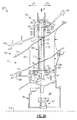
- Figure 3A is a schematic cross-sectional view of the mid-turbine frame 57 of Figure 2 , including a coupling arrangement 60 having at least one pre-skewed service line 68.
- Figures 3B to 3D show selected portions of the mid-turbine frame 57 and coupling arrangement 60 of Figure 3A .
- the coupling arrangement 60 is shown with service line 68, it should be understood that any of the spokes 66 ( Figure 2 ) can be provided with the coupling arrangement 60.
- Other fluid arrangements and portions of the engine 20 can also benefit from the teachings herein, including conduits coupled to portions of the compressor section 24 or turbine section 28 such as the low pressure turbine 46, the high pressure turbine 54, or an intermediate turbine for a three-spool engine, or adjacent structures.
- the service line 68 extends in a radial direction between an outer frame case 62 and an inner frame case 64 such that portions of the service line 68 extend through an airfoil 59.
- the service line 68 includes a proximal (or first) portion 78 coupled to the inner frame case 64 and a distal (or second) portion 80 coupled to the outer frame case 62.
- the airfoil 59 includes an airfoil section 65 extending between an outer platform 70 and an inner platform 71.
- the outer and inner platforms 70, 71 bound or otherwise define a portion of the core flow path C at the mid-turbine frame 57.
- An insulated sheath 72 can be arranged about portions of the service line 68 to reduce exposure of radiation or heat emitted from the core flow path C via the airfoil 59.
- the coupling arrangement 60 is configured such that portions of the service line 68 are pre-skewed or pre-loaded in a direction opposite to a deflection of the outer frame case 62 relative to the inner frame case 64 during operation of the engine 20. Deflection of the outer frame case 62 relative to the inner frame case 64 can be estimated, observed or otherwise determined for a particular operating condition, such as take-off or cruise, for example. A location of the distal portion 80 of the service line 68 can be caused to move rearward from a first position to a second position relative to the inner frame case 64 or frame axis B such that the distal portion 80 of the service line 68 is pre-loaded in a desired direction and at a desired distance. Pre-loading the distal portion 80 relative to the proximal portion 78 causes the service line 68 to bend or otherwise flex when in an installed position. Various techniques for pre-skewing the service line 68 can be utilized, including any of the techniques described herein.
- the coupling arrangement 60 includes a flange 74 and a capture plate 76 configured to couple the service line 68 to the mid-turbine frame 57 or adjacent structure.
- the proximal portion 78 of the service line 68 is coupled to the flange 74
- the distal portion 80 of the service line 68 is coupled to the capture plate 76.
- the flange 74 abuts or is fixedly attached to a bearing support 81
- the capture plate 76 abuts or is fixedly attached to the outer frame case 62.
- the capture plate 76 includes a collar portion 94 extending from a main body 95 in the shape of a circumferential ring or annulus defining the plate bore 85.
- the collar portion 94 has a generally planar geometry and is spaced from at least one of ends 99A, 99B of the main body 95.
- the main body 95 is at least partially received in the outer frame case 62 when the collar portion 94 is located in an installed position.
- the flange 74 is coupled to the outer frame case 62 or adjacent structure
- the capture plate 76 is coupled to the bearing support 81, the inner frame case 64, or adjacent structure.
- the flange 74 and the capture plate 76 can be coupled to the outer and inner frame cases 62, 64 or adjacent structures utilizing various techniques.
- the flange 74 includes one or more apertures 77 ( Figure 3B ) and the capture plate 76 includes one or more apertures 92 ( Figures 3C and 3D ) for receiving one or more bolts or mating portions to accept corresponding bolts.
- Other coupling techniques for attaching the flange 74 and capture plate 76 can be utilized, such as welding or the like.
- the flange 74 and the capture plate 76 are integrally formed with portions of the outer and inner frame cases 62, 64 or adjacent structures.
- the capture plate 76 and flange 74 can be made of various materials including, but not limited to, a steel alloy, a high-temperature composite or the like.
- the capture plate 76 and flange 74 can be formed utilizing various techniques, such as casting or machining processes.
- a transfer tube 75 may couple the service line 68 and the flange 74 to each other ( Figures 3A and 3B ).
- a portion of the transfer tube 75 is received in a flange bore 88 defined by the flange 74 such that the service line 68 is coupled to the flange 74.
- An inner path 82 within the transfer tube 75 is configured to communicate fluid F such as cooling airflow or lubricant between an inner passage 83 of the service line 68 and a bearing cavity 39 ( Figure 3A ) within the bearing system 38.
- the flange bore 88 contacts the service line 68 such that the flange bore 88 fluidly couples the service line 68 to the bearing cavity 39.
- the fluid F is communicated between the service line 68 and one or more bearings 41 via the bearing cavity 39.
- the bearings 41 are configured to support a shaft such as the inner shaft 40 ( Figure 1 ) radially inward of the bearing 41.
- the service line 68 includes a fitting portion 84 dimensioned to be received within a plate bore 85 defined by the capture plate 76.
- the fitting portion 84 is configured to permit the distal end 80 of the service line 68 to pivot or otherwise move relative to the capture plate 76.
- the fitting portion 84 can include various geometries to contact surfaces of the plate bore 85 depending on the needs of a particular situation.
- the fitting portion 84 is a spherical fitting having a generally spherical geometry.
- the spherical geometry of the fitting portion 84 reduces a bending moment at the distal portion 80 of the service line 68 by distributing the forces along a length of the service line 68.
- the fitting portion 84 can define at least one groove 86 for receiving a seal 87 configured to reduce leakage through the plate bore 85.
- the distal portion 80 of the service line 68 is rigidly attached to the capture plate 76.
- the capture plate 76 is arranged relative to the flange 74 such that the distal portion 80 of the service line 68 is pre-skewed in a direction substantially opposite to the deflection caused by the outer frame case 62 relative to the inner frame case 64 during operation of the engine 20.
- the service line 68 defines a conduit (or first) axis 79 ( Figure 3B ) extending between the proximal portion 78 and the distal portion 80.
- the conduit axis 79 is generally aligned with a flange (or second) axis 89 defined by flange bore 88 of the flange 74 when the proximal portion 78 of the service line 68 is coupled to the flange 74 and the distal portion 80 of the service line 68 is uncoupled from the capture plate 76.
- the capture plate 76 defines a plate (or third) axis 90 extending through plate bore 85.
- the flange axis 89 defines a first length L 1 from the aftmost portion 58B, and the plate axis 90 defines a second length L 2 from the aftmost portion 58B ( Figure 3A ).
- the flange 74 and capture plate 76 are arranged during cold assembly such that the plate axis 90 is skewed or offset relative to the flange axis 89.
- the plate axis 90 can be skewed or offset relative to the flange axis 89 by a predetermined amount and/or predetermined distance 91 such as in a direction substantially opposite to the deflection, for example.
- the conduit axis 79' ( Figure 3A ) is generally curvilinear in a radial direction between the proximal portion 78 and the distal portion 80 when the service line 68 is located in an installed position such as during cold assembly.
- the predetermined distance 91 includes an axial and/or circumferential component relative to the frame axis B or engine axis A, and can be selected depending on an anticipated thermal deflection of the outer frame case 62 relative to the inner frame case 64.
- the second length L 2 of the plate axis 90 relative to the aftmost portion 58B differs from the first length L 1 of the flange axis 89 to define the predetermined distance 91.
- the second length L 2 is less than the first length L 1 .
- the predetermined distance 91 can be selected in part based on a diameter and/or a length of the service line 68 between the outer and inner frame cases 62, 64 and a corresponding stiffness of the service line 68.
- the service line 68 can include a circular or elliptical cross-sectional geometry also affecting the stiffness of the service line 68.
- the flange 74 and capture plate 76 can be arranged such that approximately half of the stresses exerted on the distal portion 80 of the service line 68 occur in one direction, and approximately half of the stresses exerted on the distal portion 80 of the service line 68 occur in the opposition direction, thereby reducing the mean stress on the service line 68 during operation of the engine 20.
- a reduction in mean stress of the service line 68 results in an improvement in low cycle fatigue of the service line 68.
- Pre-skewing the service line 68 utilizing the techniques discussed herein can also reduce separation of the flange 74 relative to a seal interface 97 due to deflection of the outer frame case 62 relative to the inner frame case 64, thereby reducing a likelihood of unseating a seal 98 at the seal interface 97 ( Figure 3A ) and reducing seal leakage.
- the distal portion 80 of the service line 68 loaded approximately 0.053 inches in an engine forward direction D 1 along the engine axis A during operation of the engine 20.
- the distal portion 80 of the service line 68 is pre-skewed by a predetermined distance 91 of approximately 0.027 inches in an opposite engine aft direction D 2 along the engine axis A.
- a net deflection of the service line 68 is reduced to approximately 0.026 inches or approximately half of the loading in an engine forward direction D 1 during a single operating cycle of the engine 20 or aircraft.
- the capture plate 76 can have an asymmetrical geometry configured to skew the service line 68 by the predetermined distance 91.
- the plate bore 85 of the capture plate 76 is positioned or offset in an axial and/or circumferential direction by locating one or more apertures 92 defined by the capture plate 76 ( Figures 3C and 3D ).
- the apertures 92 are configured to receive fasteners to couple the capture plate 76 to the outer frame case 62.
- the apertures 92 are positioned relative to the plate axis 90 of the capture plate 76 such that the plate axis 90 is offset relative to the flange axis 89 by the predetermined distance 91 and/or in a predetermined direction.
- the plate bore 85 of the capture plate 76 is located or offset in the axial and/or circumferential direction relative to a perimeter 93 of the capture plate 76 ( Figures 3C and 3D ).
- the capture plate 76 includes an interference member 96 ( Figures 3B and 3D ) configured to prevent the capture plate 76 from being installed or positioned in an incorrect orientation.
- the interference member 96 provides a level of mistake proofing to ensure that the capture plate 76 is installed in the correct orientation such that the service line 68 is pre-skewed in a desired direction and in a desired distance.
- the interference member 96 is arranged to selectively engage surfaces of the outer frame case 62 or adjacent structure when the capture plate 76 is incorrectly installed.
- the interference member 96 extends from at least one of the collar portion 94 and the main body 95.
- the collar portion 94 is configured to abut the outer frame case 62 when the interference member 96 is located in a first position or is otherwise correctly installed ( Figure 3D ), and is configured to be spaced apart from the outer frame case 62 when the interference member 96 is located in a second position or is otherwise incorrectly installed (e.g., rotated 180 degrees such that the interference member 96 faces inwardly relative to the engine axis A).
- One method of assembling the coupling arrangement 60 is as follows.
- the flange 74 is arranged to abut the inner frame case 64 or adjacent structure such as the bearing support 81.
- the flange 74 is fixedly attached to the inner frame case 64 or adjacent structure.
- the proximal portion 78 of the service line 68 is moved in a direction from radially outward to radially inward to abut the flange 74 such that the service line 68 is coupled to the inner frame case 64 at a first axial position P 1 ( Figure 3A ).
- the proximal portion 78 of the service line 68 is coupled to the flange 74 utilizing any of the techniques described herein.
- the capture plate 76 is moved in a direction from radially outward to radially inward, for example, such that the plate bore 85 of the capture plate 76 receives the distal portion 80 of the service line 68, thereby coupling the service line 68 to the capture plate 76.
- the capture plate 76 is arranged to abut the outer frame case 62 or adjacent structure.
- the service line 68 is coupled to the capture plate 76 such that the service line 68 is coupled to outer frame case 62 at a second axial position P 2 ( Figure 3A ).
- the distal portion 80 of the service line 68 is pivotably coupled to the capture plate 76 such that the distal portion 80 is moveable relative to the second axis 89 defined by the flange 74.
- the capture plate 76 is fastened or otherwise coupled to the outer frame case 62 after the flange 74 is fastened or otherwise coupled to the inner frame case 64 to ensure tolerances of the coupling arrangement 60 do not increase or decrease skewing of the service line 68 above or below a predetermined range.
- the arrangement of the capture plate 76 in the installed position causes the distal portion 80 of the service line 68 to be pre-loaded in a predetermined direction and in a predetermined distance at cold assembly, including axial and/or circumferential components relative to one of the outer and inner frame cases 62, 64. Accordingly, the distal portion 80 of the service line 68 is pre-loaded in a first direction when in a first position relative to the inner frame case 64, such as cold assembly, and is loaded in a second, different direction when in a second different position relative to the inner frame case 64, such as during operation of the engine 20, to reduce a distance between the first axial position of the service line 68 at the inner frame case 64 and the second axial position of the service line 68 at the outer frame case 62.
- the first and second axial positions can be determined based upon thermal growth and blow off loads of the outer frame case 62 relative to the inner frame case 64 when in a first operating condition of the engine 20 such as a take-off or cruise condition.
- a magnitude of the load applied to the service line 68 in the first direction is less than or equal to a magnitude of the load in the second direction.
- the proximal portion 78 of the service line 68 is pre-skewed relative to the outer frame case 62 or frame axis B utilizing any of the techniques disclosed herein.
- FIGs 4A and 4B illustrate a coupling arrangement 160 according to a second embodiment.
- a capture plate 176 includes an interference member 196 extending from a collar portion 194 and spaced apart from a main body 195 ( Figure 4B ) of the capture plate 176.
- the interference member 196 is located adjacent to a perimeter 193 of the capture plate 176.
- the capture plate 176 is located in an installed position relative to the outer frame case 162 and receives a distal portion 180 of the service line 168.
- the interference member 196 can be configured to be at least partially received within an aperture or keyway 173 of the outer frame case 162 (shown in dashed line in Figure 4B ) when the capture plate 176 is properly installed, but contact another surface of the outer frame member 162 or adjacent structure when the capture plate 176 is improperly installed such that the collar portion 194 is spaced apart from the outer frame case 162.
- the interference member 196 is configured to selectively engage surfaces of the outer frame case 162 or adjacent structure when the capture plate 76 is incorrectly installed to space the collar portion 194 from the outer frame case 162.
Landscapes
- Engineering & Computer Science (AREA)
- Chemical & Material Sciences (AREA)
- Combustion & Propulsion (AREA)
- Mechanical Engineering (AREA)
- General Engineering & Computer Science (AREA)
- Physics & Mathematics (AREA)
- Fluid Mechanics (AREA)
- Turbine Rotor Nozzle Sealing (AREA)
- Structures Of Non-Positive Displacement Pumps (AREA)
Applications Claiming Priority (1)
| Application Number | Priority Date | Filing Date | Title |
|---|---|---|---|
| US14/715,876 US9982600B2 (en) | 2015-05-19 | 2015-05-19 | Pre-skewed capture plate |
Publications (2)
| Publication Number | Publication Date |
|---|---|
| EP3095964A1 true EP3095964A1 (fr) | 2016-11-23 |
| EP3095964B1 EP3095964B1 (fr) | 2018-11-28 |
Family
ID=56120914
Family Applications (1)
| Application Number | Title | Priority Date | Filing Date |
|---|---|---|---|
| EP16170483.8A Active EP3095964B1 (fr) | 2015-05-19 | 2016-05-19 | Plaque de capture pré-biaisée |
Country Status (2)
| Country | Link |
|---|---|
| US (1) | US9982600B2 (fr) |
| EP (1) | EP3095964B1 (fr) |
Cited By (3)
| Publication number | Priority date | Publication date | Assignee | Title |
|---|---|---|---|---|
| EP3495629A1 (fr) * | 2017-12-07 | 2019-06-12 | MTU Aero Engines GmbH | Canal d'écoulement de turbomachine |
| EP3597869A1 (fr) * | 2018-07-17 | 2020-01-22 | United Technologies Corporation | Configuration d'étanchéité pour réduire des fuites d'air |
| FR3142502A1 (fr) * | 2022-11-24 | 2024-05-31 | Safran Aircraft Engines | Carter comprenant une servitude a etancheite renforcee pour la lubrification du support de palier d'un carter de turbomachine |
Families Citing this family (10)
| Publication number | Priority date | Publication date | Assignee | Title |
|---|---|---|---|---|
| US9677663B2 (en) * | 2013-06-28 | 2017-06-13 | Sikorsky Aircraft Corporation | Gear geometry with fluid reservoir and fluid paths |
| US9915170B2 (en) * | 2015-03-20 | 2018-03-13 | United Technologies Corporation | Cooling passages for a mid-turbine frame |
| US10267334B2 (en) * | 2016-08-01 | 2019-04-23 | United Technologies Corporation | Annular heatshield |
| US11230995B2 (en) | 2017-11-08 | 2022-01-25 | Raytheon Technologies Corporation | Cable conduit for turbine engine bypass |
| US10727656B2 (en) * | 2017-11-08 | 2020-07-28 | Raytheon Technologies Corporation | Igniter cable conduit for gas turbine engine |
| US11725529B2 (en) * | 2019-02-08 | 2023-08-15 | Raytheon Technologies Corporation | Fluid transfer assembly for rotational equipment |
| US11274770B2 (en) | 2019-04-18 | 2022-03-15 | Raytheon Technologies Corporation | Monolithic fluid transfer tube |
| US11415015B2 (en) * | 2019-10-23 | 2022-08-16 | Pratt & Whitney Canada Corp. | Sleeve for oil service tubes |
| US11603770B2 (en) * | 2021-04-21 | 2023-03-14 | Raytheon Technologies Corporation | Vane assembly with integrated nozzle tube |
| JP2023172520A (ja) * | 2022-05-24 | 2023-12-06 | 三菱重工業株式会社 | タービン静翼及びガスタービン |
Citations (5)
| Publication number | Priority date | Publication date | Assignee | Title |
|---|---|---|---|---|
| US2919888A (en) * | 1957-04-17 | 1960-01-05 | United Aircraft Corp | Turbine bearing support |
| US4972671A (en) * | 1988-05-11 | 1990-11-27 | Societe Nationale D'etude Et De Construction De Moteurs D'aviation "S.N.E.C.M.A." | Turbo-engine air intake grill |
| EP1359364A1 (fr) * | 2002-04-29 | 2003-11-05 | Nuovo Pignone Holding S.P.A. | Dispositif d'étanchéité pour la traversée murale d'un tuyau |
| US20100135786A1 (en) * | 2008-11-29 | 2010-06-03 | John Alan Manteiga | Integrated service tube and impingement baffle for a gas turbine engine |
| WO2015026600A1 (fr) * | 2013-08-21 | 2015-02-26 | United Technologies Corporation | Système d'engrenage à désalignement réduit |
Family Cites Families (9)
| Publication number | Priority date | Publication date | Assignee | Title |
|---|---|---|---|---|
| US4979872A (en) | 1989-06-22 | 1990-12-25 | United Technologies Corporation | Bearing compartment support |
| US5076049A (en) * | 1990-04-02 | 1991-12-31 | General Electric Company | Pretensioned frame |
| US5483792A (en) * | 1993-05-05 | 1996-01-16 | General Electric Company | Turbine frame stiffening rails |
| US7278516B2 (en) | 2004-03-09 | 2007-10-09 | Honeywell International, Inc. | Apparatus and method for bearing lubrication in turbine engines |
| US7762087B2 (en) | 2006-12-06 | 2010-07-27 | United Technologies Corporation | Rotatable integrated segmented mid-turbine frames |
| US8061969B2 (en) | 2008-11-28 | 2011-11-22 | Pratt & Whitney Canada Corp. | Mid turbine frame system for gas turbine engine |
| US20100275572A1 (en) | 2009-04-30 | 2010-11-04 | Pratt & Whitney Canada Corp. | Oil line insulation system for mid turbine frame |
| US9097141B2 (en) | 2011-09-15 | 2015-08-04 | Pratt & Whitney Canada Corp. | Axial bolting arrangement for mid turbine frame |
| US10982565B2 (en) * | 2013-01-21 | 2021-04-20 | Raytheon Technologies Corporation | Turbine case adjustment using Adjustable tie rods |
-
2015
- 2015-05-19 US US14/715,876 patent/US9982600B2/en active Active
-
2016
- 2016-05-19 EP EP16170483.8A patent/EP3095964B1/fr active Active
Patent Citations (5)
| Publication number | Priority date | Publication date | Assignee | Title |
|---|---|---|---|---|
| US2919888A (en) * | 1957-04-17 | 1960-01-05 | United Aircraft Corp | Turbine bearing support |
| US4972671A (en) * | 1988-05-11 | 1990-11-27 | Societe Nationale D'etude Et De Construction De Moteurs D'aviation "S.N.E.C.M.A." | Turbo-engine air intake grill |
| EP1359364A1 (fr) * | 2002-04-29 | 2003-11-05 | Nuovo Pignone Holding S.P.A. | Dispositif d'étanchéité pour la traversée murale d'un tuyau |
| US20100135786A1 (en) * | 2008-11-29 | 2010-06-03 | John Alan Manteiga | Integrated service tube and impingement baffle for a gas turbine engine |
| WO2015026600A1 (fr) * | 2013-08-21 | 2015-02-26 | United Technologies Corporation | Système d'engrenage à désalignement réduit |
Cited By (5)
| Publication number | Priority date | Publication date | Assignee | Title |
|---|---|---|---|---|
| EP3495629A1 (fr) * | 2017-12-07 | 2019-06-12 | MTU Aero Engines GmbH | Canal d'écoulement de turbomachine |
| US11098599B2 (en) | 2017-12-07 | 2021-08-24 | MTU Aero Engines AG | Flow channel for a turbomachine |
| EP3597869A1 (fr) * | 2018-07-17 | 2020-01-22 | United Technologies Corporation | Configuration d'étanchéité pour réduire des fuites d'air |
| US10830077B2 (en) | 2018-07-17 | 2020-11-10 | Raytheon Technologies Corporation | Sealing configuration to reduce air leakage |
| FR3142502A1 (fr) * | 2022-11-24 | 2024-05-31 | Safran Aircraft Engines | Carter comprenant une servitude a etancheite renforcee pour la lubrification du support de palier d'un carter de turbomachine |
Also Published As
| Publication number | Publication date |
|---|---|
| US20160341123A1 (en) | 2016-11-24 |
| EP3095964B1 (fr) | 2018-11-28 |
| US9982600B2 (en) | 2018-05-29 |
Similar Documents
| Publication | Publication Date | Title |
|---|---|---|
| EP3095964B1 (fr) | Plaque de capture pré-biaisée | |
| US10577971B2 (en) | Integrated inner case heat shield | |
| US11536204B2 (en) | Method of assembly for gear system with rotating carrier | |
| EP4640993A2 (fr) | Fixation de broche pour composants cmc dans un moteur à turbine à gaz | |
| US10605119B2 (en) | Turbine frame assembly for gas turbine engines | |
| US11421558B2 (en) | Gas turbine engine component | |
| EP3447251B1 (fr) | Ensemble d'étanchéité pour moteurs à turbine à gaz | |
| EP2888463B1 (fr) | Joint d'étanchéité annulaire de turbomachine et écran thermique | |
| EP4086436A1 (fr) | Assemblages d'une aube statorique d'une turbine á gaz | |
| US10753220B2 (en) | Gas turbine engine component | |
| EP3524777B1 (fr) | Empilement de rotor de compresseur haute pression, moteur de turbine à gaz associé et méthode de diriger un fluide à travers un empilement de rotor de compresseur haute pression | |
| EP3045683A1 (fr) | Passages de refroidissement pour un cadre de turbine intermédiaire | |
| EP3650721B1 (fr) | Ressort de centrage pour compartiment de palier de moteur à turbine à gaz | |
| EP3045665A1 (fr) | Ensemble de cadre de turbine intermédiaire avec jambe de force pour un moteur à turbine à gaz | |
| EP3708773B1 (fr) | Moteur à turbine à gaz avec joint d'étanchéité pour un empilement de rotors et procédé associé pour rendre étanche un arbre par rapport à un disque de rotor | |
| US10422237B2 (en) | Flow diverter case attachment for gas turbine engine | |
| EP3282101B1 (fr) | Cale pour moteur de turbine à gaz | |
| EP3760842A1 (fr) | Conduit composite d'un moteur à turbine à gaz doté d'un support | |
| EP3000989B1 (fr) | Système d'engrenage d'entraînement de soufflante | |
| EP3812555B1 (fr) | Agencement de retour d'huile pour moteur à turbine à gaz |
Legal Events
| Date | Code | Title | Description |
|---|---|---|---|
| PUAI | Public reference made under article 153(3) epc to a published international application that has entered the european phase |
Free format text: ORIGINAL CODE: 0009012 |
|
| AK | Designated contracting states |
Kind code of ref document: A1 Designated state(s): AL AT BE BG CH CY CZ DE DK EE ES FI FR GB GR HR HU IE IS IT LI LT LU LV MC MK MT NL NO PL PT RO RS SE SI SK SM TR |
|
| AX | Request for extension of the european patent |
Extension state: BA ME |
|
| STAA | Information on the status of an ep patent application or granted ep patent |
Free format text: STATUS: REQUEST FOR EXAMINATION WAS MADE |
|
| 17P | Request for examination filed |
Effective date: 20170523 |
|
| RBV | Designated contracting states (corrected) |
Designated state(s): AL AT BE BG CH CY CZ DE DK EE ES FI FR GB GR HR HU IE IS IT LI LT LU LV MC MK MT NL NO PL PT RO RS SE SI SK SM TR |
|
| GRAP | Despatch of communication of intention to grant a patent |
Free format text: ORIGINAL CODE: EPIDOSNIGR1 |
|
| RIC1 | Information provided on ipc code assigned before grant |
Ipc: F01D 9/06 20060101AFI20180420BHEP |
|
| STAA | Information on the status of an ep patent application or granted ep patent |
Free format text: STATUS: GRANT OF PATENT IS INTENDED |
|
| INTG | Intention to grant announced |
Effective date: 20180531 |
|
| RIN1 | Information on inventor provided before grant (corrected) |
Inventor name: BULKOVITCH, JR., RICHARD JOSEPH Inventor name: REUBEN, JONATHAN C. Inventor name: HONIOUS, KELSEY Inventor name: COMEAU, MICHAEL LUTHER Inventor name: SOCHA, PAWEL Inventor name: KHAN, USMAN |
|
| GRAS | Grant fee paid |
Free format text: ORIGINAL CODE: EPIDOSNIGR3 |
|
| GRAA | (expected) grant |
Free format text: ORIGINAL CODE: 0009210 |
|
| STAA | Information on the status of an ep patent application or granted ep patent |
Free format text: STATUS: THE PATENT HAS BEEN GRANTED |
|
| AK | Designated contracting states |
Kind code of ref document: B1 Designated state(s): AL AT BE BG CH CY CZ DE DK EE ES FI FR GB GR HR HU IE IS IT LI LT LU LV MC MK MT NL NO PL PT RO RS SE SI SK SM TR |
|
| REG | Reference to a national code |
Ref country code: CH Ref legal event code: EP |
|
| REG | Reference to a national code |
Ref country code: AT Ref legal event code: REF Ref document number: 1070484 Country of ref document: AT Kind code of ref document: T Effective date: 20181215 |
|
| REG | Reference to a national code |
Ref country code: IE Ref legal event code: FG4D |
|
| REG | Reference to a national code |
Ref country code: DE Ref legal event code: R096 Ref document number: 602016007507 Country of ref document: DE |
|
| REG | Reference to a national code |
Ref country code: NL Ref legal event code: MP Effective date: 20181128 |
|
| REG | Reference to a national code |
Ref country code: LT Ref legal event code: MG4D |
|
| REG | Reference to a national code |
Ref country code: AT Ref legal event code: MK05 Ref document number: 1070484 Country of ref document: AT Kind code of ref document: T Effective date: 20181128 |
|
| PG25 | Lapsed in a contracting state [announced via postgrant information from national office to epo] |
Ref country code: FI Free format text: LAPSE BECAUSE OF FAILURE TO SUBMIT A TRANSLATION OF THE DESCRIPTION OR TO PAY THE FEE WITHIN THE PRESCRIBED TIME-LIMIT Effective date: 20181128 Ref country code: IS Free format text: LAPSE BECAUSE OF FAILURE TO SUBMIT A TRANSLATION OF THE DESCRIPTION OR TO PAY THE FEE WITHIN THE PRESCRIBED TIME-LIMIT Effective date: 20190328 Ref country code: LT Free format text: LAPSE BECAUSE OF FAILURE TO SUBMIT A TRANSLATION OF THE DESCRIPTION OR TO PAY THE FEE WITHIN THE PRESCRIBED TIME-LIMIT Effective date: 20181128 Ref country code: BG Free format text: LAPSE BECAUSE OF FAILURE TO SUBMIT A TRANSLATION OF THE DESCRIPTION OR TO PAY THE FEE WITHIN THE PRESCRIBED TIME-LIMIT Effective date: 20190228 Ref country code: HR Free format text: LAPSE BECAUSE OF FAILURE TO SUBMIT A TRANSLATION OF THE DESCRIPTION OR TO PAY THE FEE WITHIN THE PRESCRIBED TIME-LIMIT Effective date: 20181128 Ref country code: LV Free format text: LAPSE BECAUSE OF FAILURE TO SUBMIT A TRANSLATION OF THE DESCRIPTION OR TO PAY THE FEE WITHIN THE PRESCRIBED TIME-LIMIT Effective date: 20181128 Ref country code: ES Free format text: LAPSE BECAUSE OF FAILURE TO SUBMIT A TRANSLATION OF THE DESCRIPTION OR TO PAY THE FEE WITHIN THE PRESCRIBED TIME-LIMIT Effective date: 20181128 Ref country code: AT Free format text: LAPSE BECAUSE OF FAILURE TO SUBMIT A TRANSLATION OF THE DESCRIPTION OR TO PAY THE FEE WITHIN THE PRESCRIBED TIME-LIMIT Effective date: 20181128 Ref country code: NO Free format text: LAPSE BECAUSE OF FAILURE TO SUBMIT A TRANSLATION OF THE DESCRIPTION OR TO PAY THE FEE WITHIN THE PRESCRIBED TIME-LIMIT Effective date: 20190228 |
|
| PG25 | Lapsed in a contracting state [announced via postgrant information from national office to epo] |
Ref country code: GR Free format text: LAPSE BECAUSE OF FAILURE TO SUBMIT A TRANSLATION OF THE DESCRIPTION OR TO PAY THE FEE WITHIN THE PRESCRIBED TIME-LIMIT Effective date: 20190301 Ref country code: PT Free format text: LAPSE BECAUSE OF FAILURE TO SUBMIT A TRANSLATION OF THE DESCRIPTION OR TO PAY THE FEE WITHIN THE PRESCRIBED TIME-LIMIT Effective date: 20190328 Ref country code: RS Free format text: LAPSE BECAUSE OF FAILURE TO SUBMIT A TRANSLATION OF THE DESCRIPTION OR TO PAY THE FEE WITHIN THE PRESCRIBED TIME-LIMIT Effective date: 20181128 Ref country code: AL Free format text: LAPSE BECAUSE OF FAILURE TO SUBMIT A TRANSLATION OF THE DESCRIPTION OR TO PAY THE FEE WITHIN THE PRESCRIBED TIME-LIMIT Effective date: 20181128 Ref country code: SE Free format text: LAPSE BECAUSE OF FAILURE TO SUBMIT A TRANSLATION OF THE DESCRIPTION OR TO PAY THE FEE WITHIN THE PRESCRIBED TIME-LIMIT Effective date: 20181128 |
|
| PG25 | Lapsed in a contracting state [announced via postgrant information from national office to epo] |
Ref country code: NL Free format text: LAPSE BECAUSE OF FAILURE TO SUBMIT A TRANSLATION OF THE DESCRIPTION OR TO PAY THE FEE WITHIN THE PRESCRIBED TIME-LIMIT Effective date: 20181128 |
|
| PG25 | Lapsed in a contracting state [announced via postgrant information from national office to epo] |
Ref country code: IT Free format text: LAPSE BECAUSE OF FAILURE TO SUBMIT A TRANSLATION OF THE DESCRIPTION OR TO PAY THE FEE WITHIN THE PRESCRIBED TIME-LIMIT Effective date: 20181128 Ref country code: CZ Free format text: LAPSE BECAUSE OF FAILURE TO SUBMIT A TRANSLATION OF THE DESCRIPTION OR TO PAY THE FEE WITHIN THE PRESCRIBED TIME-LIMIT Effective date: 20181128 Ref country code: DK Free format text: LAPSE BECAUSE OF FAILURE TO SUBMIT A TRANSLATION OF THE DESCRIPTION OR TO PAY THE FEE WITHIN THE PRESCRIBED TIME-LIMIT Effective date: 20181128 Ref country code: PL Free format text: LAPSE BECAUSE OF FAILURE TO SUBMIT A TRANSLATION OF THE DESCRIPTION OR TO PAY THE FEE WITHIN THE PRESCRIBED TIME-LIMIT Effective date: 20181128 |
|
| REG | Reference to a national code |
Ref country code: DE Ref legal event code: R097 Ref document number: 602016007507 Country of ref document: DE |
|
| PG25 | Lapsed in a contracting state [announced via postgrant information from national office to epo] |
Ref country code: SK Free format text: LAPSE BECAUSE OF FAILURE TO SUBMIT A TRANSLATION OF THE DESCRIPTION OR TO PAY THE FEE WITHIN THE PRESCRIBED TIME-LIMIT Effective date: 20181128 Ref country code: EE Free format text: LAPSE BECAUSE OF FAILURE TO SUBMIT A TRANSLATION OF THE DESCRIPTION OR TO PAY THE FEE WITHIN THE PRESCRIBED TIME-LIMIT Effective date: 20181128 Ref country code: SM Free format text: LAPSE BECAUSE OF FAILURE TO SUBMIT A TRANSLATION OF THE DESCRIPTION OR TO PAY THE FEE WITHIN THE PRESCRIBED TIME-LIMIT Effective date: 20181128 Ref country code: RO Free format text: LAPSE BECAUSE OF FAILURE TO SUBMIT A TRANSLATION OF THE DESCRIPTION OR TO PAY THE FEE WITHIN THE PRESCRIBED TIME-LIMIT Effective date: 20181128 |
|
| PLBE | No opposition filed within time limit |
Free format text: ORIGINAL CODE: 0009261 |
|
| STAA | Information on the status of an ep patent application or granted ep patent |
Free format text: STATUS: NO OPPOSITION FILED WITHIN TIME LIMIT |
|
| PG25 | Lapsed in a contracting state [announced via postgrant information from national office to epo] |
Ref country code: SI Free format text: LAPSE BECAUSE OF FAILURE TO SUBMIT A TRANSLATION OF THE DESCRIPTION OR TO PAY THE FEE WITHIN THE PRESCRIBED TIME-LIMIT Effective date: 20181128 |
|
| 26N | No opposition filed |
Effective date: 20190829 |
|
| REG | Reference to a national code |
Ref country code: CH Ref legal event code: PL |
|
| PG25 | Lapsed in a contracting state [announced via postgrant information from national office to epo] |
Ref country code: MC Free format text: LAPSE BECAUSE OF FAILURE TO SUBMIT A TRANSLATION OF THE DESCRIPTION OR TO PAY THE FEE WITHIN THE PRESCRIBED TIME-LIMIT Effective date: 20181128 Ref country code: CH Free format text: LAPSE BECAUSE OF NON-PAYMENT OF DUE FEES Effective date: 20190531 Ref country code: LI Free format text: LAPSE BECAUSE OF NON-PAYMENT OF DUE FEES Effective date: 20190531 |
|
| REG | Reference to a national code |
Ref country code: BE Ref legal event code: MM Effective date: 20190531 |
|
| PG25 | Lapsed in a contracting state [announced via postgrant information from national office to epo] |
Ref country code: LU Free format text: LAPSE BECAUSE OF NON-PAYMENT OF DUE FEES Effective date: 20190519 |
|
| PG25 | Lapsed in a contracting state [announced via postgrant information from national office to epo] |
Ref country code: TR Free format text: LAPSE BECAUSE OF FAILURE TO SUBMIT A TRANSLATION OF THE DESCRIPTION OR TO PAY THE FEE WITHIN THE PRESCRIBED TIME-LIMIT Effective date: 20181128 |
|
| PG25 | Lapsed in a contracting state [announced via postgrant information from national office to epo] |
Ref country code: IE Free format text: LAPSE BECAUSE OF NON-PAYMENT OF DUE FEES Effective date: 20190519 |
|
| PG25 | Lapsed in a contracting state [announced via postgrant information from national office to epo] |
Ref country code: BE Free format text: LAPSE BECAUSE OF NON-PAYMENT OF DUE FEES Effective date: 20190531 |
|
| PG25 | Lapsed in a contracting state [announced via postgrant information from national office to epo] |
Ref country code: CY Free format text: LAPSE BECAUSE OF FAILURE TO SUBMIT A TRANSLATION OF THE DESCRIPTION OR TO PAY THE FEE WITHIN THE PRESCRIBED TIME-LIMIT Effective date: 20181128 |
|
| PG25 | Lapsed in a contracting state [announced via postgrant information from national office to epo] |
Ref country code: HU Free format text: LAPSE BECAUSE OF FAILURE TO SUBMIT A TRANSLATION OF THE DESCRIPTION OR TO PAY THE FEE WITHIN THE PRESCRIBED TIME-LIMIT; INVALID AB INITIO Effective date: 20160519 Ref country code: MT Free format text: LAPSE BECAUSE OF FAILURE TO SUBMIT A TRANSLATION OF THE DESCRIPTION OR TO PAY THE FEE WITHIN THE PRESCRIBED TIME-LIMIT Effective date: 20181128 |
|
| PG25 | Lapsed in a contracting state [announced via postgrant information from national office to epo] |
Ref country code: MK Free format text: LAPSE BECAUSE OF FAILURE TO SUBMIT A TRANSLATION OF THE DESCRIPTION OR TO PAY THE FEE WITHIN THE PRESCRIBED TIME-LIMIT Effective date: 20181128 |
|
| REG | Reference to a national code |
Ref country code: DE Ref legal event code: R081 Ref document number: 602016007507 Country of ref document: DE Owner name: RAYTHEON TECHNOLOGIES CORPORATION (N.D.GES.D.S, US Free format text: FORMER OWNER: UNITED TECHNOLOGIES CORPORATION, FARMINGTON, CONN., US Ref country code: DE Ref legal event code: R081 Ref document number: 602016007507 Country of ref document: DE Owner name: RTX CORPORATION (N.D.GES.D. STAATES DELAWARE),, US Free format text: FORMER OWNER: UNITED TECHNOLOGIES CORPORATION, FARMINGTON, CONN., US |
|
| P01 | Opt-out of the competence of the unified patent court (upc) registered |
Effective date: 20230520 |
|
| PGFP | Annual fee paid to national office [announced via postgrant information from national office to epo] |
Ref country code: DE Payment date: 20250423 Year of fee payment: 10 |
|
| PGFP | Annual fee paid to national office [announced via postgrant information from national office to epo] |
Ref country code: GB Payment date: 20250423 Year of fee payment: 10 |
|
| PGFP | Annual fee paid to national office [announced via postgrant information from national office to epo] |
Ref country code: FR Payment date: 20250423 Year of fee payment: 10 |
|
| REG | Reference to a national code |
Ref country code: DE Ref legal event code: R081 Ref document number: 602016007507 Country of ref document: DE Owner name: RTX CORPORATION (N.D.GES.D. STAATES DELAWARE),, US Free format text: FORMER OWNER: RAYTHEON TECHNOLOGIES CORPORATION (N.D.GES.D.STAATES DELAWARE), ARLINGTON, VA, US |