EP3095965B1 - Gasturbinentriebwerkskomponente und zugehöriges gasturbinentriebwerk - Google Patents
Gasturbinentriebwerkskomponente und zugehöriges gasturbinentriebwerk Download PDFInfo
- Publication number
- EP3095965B1 EP3095965B1 EP16166361.2A EP16166361A EP3095965B1 EP 3095965 B1 EP3095965 B1 EP 3095965B1 EP 16166361 A EP16166361 A EP 16166361A EP 3095965 B1 EP3095965 B1 EP 3095965B1
- Authority
- EP
- European Patent Office
- Prior art keywords
- gas turbine
- turbine engine
- component according
- engine component
- hard particles
- Prior art date
- Legal status (The legal status is an assumption and is not a legal conclusion. Google has not performed a legal analysis and makes no representation as to the accuracy of the status listed.)
- Active
Links
Images


Classifications
-
- F—MECHANICAL ENGINEERING; LIGHTING; HEATING; WEAPONS; BLASTING
- F01—MACHINES OR ENGINES IN GENERAL; ENGINE PLANTS IN GENERAL; STEAM ENGINES
- F01D—NON-POSITIVE DISPLACEMENT MACHINES OR ENGINES, e.g. STEAM TURBINES
- F01D5/00—Blades; Blade-carrying members; Heating, heat-insulating, cooling or antivibration means on the blades or the members
- F01D5/12—Blades
- F01D5/28—Selecting particular materials; Particular measures relating thereto; Measures against erosion or corrosion
- F01D5/288—Protective coatings for blades
-
- F—MECHANICAL ENGINEERING; LIGHTING; HEATING; WEAPONS; BLASTING
- F01—MACHINES OR ENGINES IN GENERAL; ENGINE PLANTS IN GENERAL; STEAM ENGINES
- F01D—NON-POSITIVE DISPLACEMENT MACHINES OR ENGINES, e.g. STEAM TURBINES
- F01D11/00—Preventing or minimising internal leakage of working-fluid, e.g. between stages
- F01D11/08—Preventing or minimising internal leakage of working-fluid, e.g. between stages for sealing space between rotor blade tips and stator
- F01D11/12—Preventing or minimising internal leakage of working-fluid, e.g. between stages for sealing space between rotor blade tips and stator using a rubstrip, e.g. erodible. deformable or resiliently-biased part
- F01D11/122—Preventing or minimising internal leakage of working-fluid, e.g. between stages for sealing space between rotor blade tips and stator using a rubstrip, e.g. erodible. deformable or resiliently-biased part with erodable or abradable material
-
- F—MECHANICAL ENGINEERING; LIGHTING; HEATING; WEAPONS; BLASTING
- F01—MACHINES OR ENGINES IN GENERAL; ENGINE PLANTS IN GENERAL; STEAM ENGINES
- F01D—NON-POSITIVE DISPLACEMENT MACHINES OR ENGINES, e.g. STEAM TURBINES
- F01D5/00—Blades; Blade-carrying members; Heating, heat-insulating, cooling or antivibration means on the blades or the members
- F01D5/12—Blades
- F01D5/14—Form or construction
- F01D5/147—Construction, i.e. structural features, e.g. of weight-saving hollow blades
-
- F—MECHANICAL ENGINEERING; LIGHTING; HEATING; WEAPONS; BLASTING
- F01—MACHINES OR ENGINES IN GENERAL; ENGINE PLANTS IN GENERAL; STEAM ENGINES
- F01D—NON-POSITIVE DISPLACEMENT MACHINES OR ENGINES, e.g. STEAM TURBINES
- F01D5/00—Blades; Blade-carrying members; Heating, heat-insulating, cooling or antivibration means on the blades or the members
- F01D5/12—Blades
- F01D5/14—Form or construction
- F01D5/20—Specially-shaped blade tips to seal space between tips and stator
-
- F—MECHANICAL ENGINEERING; LIGHTING; HEATING; WEAPONS; BLASTING
- F05—INDEXING SCHEMES RELATING TO ENGINES OR PUMPS IN VARIOUS SUBCLASSES OF CLASSES F01-F04
- F05D—INDEXING SCHEME FOR ASPECTS RELATING TO NON-POSITIVE-DISPLACEMENT MACHINES OR ENGINES, GAS-TURBINES OR JET-PROPULSION PLANTS
- F05D2220/00—Application
- F05D2220/30—Application in turbines
- F05D2220/32—Application in turbines in gas turbines
-
- F—MECHANICAL ENGINEERING; LIGHTING; HEATING; WEAPONS; BLASTING
- F05—INDEXING SCHEMES RELATING TO ENGINES OR PUMPS IN VARIOUS SUBCLASSES OF CLASSES F01-F04
- F05D—INDEXING SCHEME FOR ASPECTS RELATING TO NON-POSITIVE-DISPLACEMENT MACHINES OR ENGINES, GAS-TURBINES OR JET-PROPULSION PLANTS
- F05D2230/00—Manufacture
- F05D2230/90—Coating; Surface treatment
-
- F—MECHANICAL ENGINEERING; LIGHTING; HEATING; WEAPONS; BLASTING
- F05—INDEXING SCHEMES RELATING TO ENGINES OR PUMPS IN VARIOUS SUBCLASSES OF CLASSES F01-F04
- F05D—INDEXING SCHEME FOR ASPECTS RELATING TO NON-POSITIVE-DISPLACEMENT MACHINES OR ENGINES, GAS-TURBINES OR JET-PROPULSION PLANTS
- F05D2240/00—Components
- F05D2240/20—Rotors
- F05D2240/30—Characteristics of rotor blades, i.e. of any element transforming dynamic fluid energy to or from rotational energy and being attached to a rotor
- F05D2240/307—Characteristics of rotor blades, i.e. of any element transforming dynamic fluid energy to or from rotational energy and being attached to a rotor related to the tip of a rotor blade
-
- F—MECHANICAL ENGINEERING; LIGHTING; HEATING; WEAPONS; BLASTING
- F05—INDEXING SCHEMES RELATING TO ENGINES OR PUMPS IN VARIOUS SUBCLASSES OF CLASSES F01-F04
- F05D—INDEXING SCHEME FOR ASPECTS RELATING TO NON-POSITIVE-DISPLACEMENT MACHINES OR ENGINES, GAS-TURBINES OR JET-PROPULSION PLANTS
- F05D2300/00—Materials; Properties thereof
- F05D2300/10—Metals, alloys or intermetallic compounds
- F05D2300/17—Alloys
- F05D2300/171—Steel alloys
-
- F—MECHANICAL ENGINEERING; LIGHTING; HEATING; WEAPONS; BLASTING
- F05—INDEXING SCHEMES RELATING TO ENGINES OR PUMPS IN VARIOUS SUBCLASSES OF CLASSES F01-F04
- F05D—INDEXING SCHEME FOR ASPECTS RELATING TO NON-POSITIVE-DISPLACEMENT MACHINES OR ENGINES, GAS-TURBINES OR JET-PROPULSION PLANTS
- F05D2300/00—Materials; Properties thereof
- F05D2300/10—Metals, alloys or intermetallic compounds
- F05D2300/17—Alloys
- F05D2300/174—Titanium alloys, e.g. TiAl
-
- F—MECHANICAL ENGINEERING; LIGHTING; HEATING; WEAPONS; BLASTING
- F05—INDEXING SCHEMES RELATING TO ENGINES OR PUMPS IN VARIOUS SUBCLASSES OF CLASSES F01-F04
- F05D—INDEXING SCHEME FOR ASPECTS RELATING TO NON-POSITIVE-DISPLACEMENT MACHINES OR ENGINES, GAS-TURBINES OR JET-PROPULSION PLANTS
- F05D2300/00—Materials; Properties thereof
- F05D2300/10—Metals, alloys or intermetallic compounds
- F05D2300/17—Alloys
- F05D2300/175—Superalloys
-
- F—MECHANICAL ENGINEERING; LIGHTING; HEATING; WEAPONS; BLASTING
- F05—INDEXING SCHEMES RELATING TO ENGINES OR PUMPS IN VARIOUS SUBCLASSES OF CLASSES F01-F04
- F05D—INDEXING SCHEME FOR ASPECTS RELATING TO NON-POSITIVE-DISPLACEMENT MACHINES OR ENGINES, GAS-TURBINES OR JET-PROPULSION PLANTS
- F05D2300/00—Materials; Properties thereof
- F05D2300/10—Metals, alloys or intermetallic compounds
- F05D2300/17—Alloys
- F05D2300/177—Ni - Si alloys
-
- F—MECHANICAL ENGINEERING; LIGHTING; HEATING; WEAPONS; BLASTING
- F05—INDEXING SCHEMES RELATING TO ENGINES OR PUMPS IN VARIOUS SUBCLASSES OF CLASSES F01-F04
- F05D—INDEXING SCHEME FOR ASPECTS RELATING TO NON-POSITIVE-DISPLACEMENT MACHINES OR ENGINES, GAS-TURBINES OR JET-PROPULSION PLANTS
- F05D2300/00—Materials; Properties thereof
- F05D2300/20—Oxide or non-oxide ceramics
- F05D2300/22—Non-oxide ceramics
- F05D2300/228—Nitrides
- F05D2300/2282—Nitrides of boron
-
- F—MECHANICAL ENGINEERING; LIGHTING; HEATING; WEAPONS; BLASTING
- F05—INDEXING SCHEMES RELATING TO ENGINES OR PUMPS IN VARIOUS SUBCLASSES OF CLASSES F01-F04
- F05D—INDEXING SCHEME FOR ASPECTS RELATING TO NON-POSITIVE-DISPLACEMENT MACHINES OR ENGINES, GAS-TURBINES OR JET-PROPULSION PLANTS
- F05D2300/00—Materials; Properties thereof
- F05D2300/60—Properties or characteristics given to material by treatment or manufacturing
- F05D2300/603—Composites; e.g. fibre-reinforced
- F05D2300/6032—Metal matrix composites [MMC]
Definitions
- the present invention relates to a gas turbine engine component with an abrasive coating.
- FIG. 1 shows (a) a smooth tipped turbine blade 31 with an abrasive coating 33, and (b) a cross section through the blade and coating.
- the abrasive coating comprises hard particles 35 embedded in a retaining matrix 37.
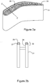
- Figure 2 shows (a) a squealer tipped turbine blade 31 with an abrasive coating 33, and (b) a cross section through the blade and coating.
- the abrasive coating, containing the hard particles 35 and the retaining matrix 37, is attached to the narrow projecting lips 38 of the squealer tip. Due to their location close to the edges of the lips, hard particles may fall off. This may result in the abrasive coating having a reduced number of hard particles, decreasing the effectiveness of the coating.
- the abrasive coating on both the smooth and the squealer tipped blades is generally attached to a smooth surface.
- the strength of the coating or the strength of the attachment between the coating and smooth surface may be insufficient to prevent the coating from being smeared off.
- US patent publication 2008/166225 discloses a turbine blade tip and shroud clearance control coating system comprising an abrasive tip coating and abradable shroud coating.
- the abrasive layer may comprise abrasive particles of cubic zirconia, cubic hafnia or mixtures thereof, and the abradable layer may be a nanolaminate thermal barrier coating that is softer than the abrasive layer.
- This publication further provides an alternate coating system comprising an abradable blade tip coating and an abrasive shroud coating.
- US4227703 discloses a gas seal between a stationary member and a movable member, one of which includes an abrasive tipped projection directed toward a surface of the other.
- One example comprises a turbine engine blade and a cooperating shroud member, one of which has an abrasive tip.
- the tip of the projection is a composite of inner and outer tip portions, the inner portion comprising an alloy resistant to oxidation, sulfidation and thermal fatigue at operating temperatures and the outer tip portion comprising a matrix entrapping a plurality of abrasive particles which protrude from the matrix toward the surface of the other member.
- the inner tip portion is bonded with the metallic body of the projection and the outer tip portion is deposited on the inner tip portion.
- the present invention aims to provide a gas turbine engine component with an abrasive coating which can reduce aerodynamic loses, decrease interference with component cooling systems, and improve the attachment of the coating to the component.
- the present invention provides a gas turbine engine component as set out in claim 1.
- the present invention provides a gas turbine engine as set out in claim 9.
- Optional features of the invention are set out in the dependent claims.
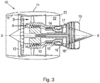
- a ducted fan gas turbine engine incorporating the invention is generally indicated at 10 and has a principal and rotational axis X-X.
- the engine comprises, in axial flow series, an air intake 11, a propulsive fan 12, an intermediate pressure compressor 13, a high-pressure compressor 14, combustion equipment 15, a high-pressure turbine 16, an intermediate pressure turbine 17, a low-pressure turbine 18 and a core engine exhaust nozzle 19.
- a nacelle 21 generally surrounds the engine 10 and defines the intake 11, a bypass duct 22 and a bypass exhaust nozzle 23.
- air entering the intake 11 is accelerated by the fan 12 to produce two air flows: a first air flow A into the intermediate-pressure compressor 13 and a second air flow B which passes through the bypass duct 22 to provide propulsive thrust.
- the intermediate-pressure compressor 13 compresses the air flow A directed into it before delivering that air to the high-pressure compressor 14 where further compression takes place.
- the compressed air exhausted from the high-pressure compressor 14 is directed into the combustion equipment 15 where it is mixed with fuel and the mixture combusted.
- the resultant hot combustion products then expand through, and thereby drive the high, intermediate and low-pressure turbines 16, 17, 18 before being exhausted through the nozzle 19 to provide additional propulsive thrust.
- the high, intermediate and low-pressure turbines respectively drive the high and intermediate-pressure compressors 14, 13 and the fan 12 by suitable interconnecting shafts.
- the engine 10 contains turbine blades, and the tips of these blades may be coated in an abrasive coating as shown in the schematic cross section through an abrasive tipped turbine blade of Figure 4 .
- the blade is typically made of a nickel-based superalloy, such as In718, Nimonic 75 or Nimonic 102.
- similarly coated rotor blades may be formed of steel or a titanium-based alloy, such as Ti-6AI-4.
- the turbine blade 1 has a raised rim 9 located along the outer edges of the tip of the blade.
- the rim bounds an inner area of the tip region on which is formed an abrasive coating 3 including hard particles 5 of cubic boron nitride embedded in a retaining matrix 7 of nickel.
- the raised rim has a height in a span direction of approximately 0.15mm.
- the rim helps to anchor the coating on the tip, provides resistance to plastic deformation of the matrix, and reduces the likelihood of the abrasive coating being smeared off from the blade when in use.
- the rim corrals the particles, providing a stop and support to prevent particles being located near an outer edge of the blade tip, and either falling off or causing an unwanted build-up of retaining matrix along the outer edges.
- the rim can improve the aerodynamics of the coated blade and reduce any negative impact of the coating on the blade's film cooling system.
- the hard particles 5 typically have a mean diameter of between 0.18 and 0.25mm. Consequently, the raised rim has a height of between 50% and 75% of the mean diameter of the hard particles 5.
- the hard particles 5 are located such that they project beyond the raised rim and in use, abrade a runner surface of a casing surrounding the blade. To prevent the particles falling out, they are held in place by the matrix 7, which can be applied by electroplating.
- the matrix 7, which can be applied by electroplating for example, Praxair Surface Technologies TBT406TM electroplating process or Abrasive Technologies ATA3CTM electroplating process may be used.
- an electroplated entrapment layer entraps undersides of the abrasive particles to hold them in position on the blade, and then the retaining matrix is electroplated to complete the coating.
- alternative matrix materials such as cobalt, iron or an alloy of any one or more thereof, and alternative methods of attachment may be used.
- the matrix could comprise NiCoCrAIY.
- the present invention is a squealer tipped turbine blade having the abrasive coating.
- the raised rim runs along both edges of each projecting lip of the squealer tip, and the abrasive coating runs along the centre of each lip where it is bounded on both sides by the raised rim.
- the raised rims can be produced by casting, electro-discharge machining, milling or an additive layer manufacturing process such as laser cladding.
- the abrasive coating can be usefully applied to the tips of other rotor blades such as compressor blades or fan blades such that the coating abrades a runner surface of a surrounding casing.
Landscapes
- Engineering & Computer Science (AREA)
- Mechanical Engineering (AREA)
- General Engineering & Computer Science (AREA)
- Chemical & Material Sciences (AREA)
- Materials Engineering (AREA)
- Architecture (AREA)
- Turbine Rotor Nozzle Sealing (AREA)
- Structures Of Non-Positive Displacement Pumps (AREA)
Claims (9)
- Gasturbinentriebwerkskomponente (1), die Folgendes umfasst:eine Rotorschaufel (1) mit einer Squealer-Spitze, die mindestens eine vorstehende Lippe umfasst, dadurch gekennzeichnet, dass die Rotorschaufel einen erhöhten Rand (9) aufweist, der entlang beider Kanten von jeder vorstehenden Lippe der Squealer-Spitze verläuft,eine Schleifbeschichtung (3), die entlang der Mitte von jeder vorstehenden Lippe verläuft, wo sie auf beiden Seiten durch den erhöhten Rand begrenzt ist undden Spitzenbereich in einem Gebiet, das durch den erhöhten Rand begrenzt ist, bedeckt,wobei die Schleifbeschichtung aus harten Partikeln (5) ausgebildet ist, die in einer Haltematrix (7) eingebettet sind,wobei der erhöhte Rand eineHöhe zwischen 50 % und 75 % des mittleren Durchmessers der harten Partikel aufweist.
- Gasturbinentriebwerkskomponente nach Anspruch 1, wobei die harten Partikel kubische Bornitridpartikel sind.
- Gasturbinentriebwerkskomponente nach Anspruch 1 oder 2, wobei die Haltematrix Nickel, Cobalt, Eisen oder eine Legierung aus einem oder mehreren davon ist.
- Gasturbinentriebwerkskomponente nach einem der vorhergehenden Ansprüche, wobei die harten Partikel über den erhöhten Rand hervorstehen, sodass die harten Partikel bei Verwendung eine Lauffläche einer benachbarten Komponente abschleifen.
- Gasturbinentriebwerkskomponente nach einem der vorhergehenden Ansprüche, wobei die Haltematrix galvanisiert wird.
- Gasturbinentriebwerkskomponente nach einem der vorhergehenden Ansprüche, wobei der erhöhte Rand eine Höhe von ungefähr 0,15 mm aufweist.
- Gasturbinentriebwerkskomponente nach einem der vorhergehenden Ansprüche, wobei die harten Partikel einen mittleren Durchmesser zwischen 0,18 und 0,25 mm aufweisen.
- Gasturbinentriebwerkskomponente nach einem der vorhergehenden Ansprüche, wobei der erhöhte Rand durch Gießen, Funkenerodieren, Fräsen oder Additivschichtherstellungsverfahren, wie z. B. Laserplattieren hergestellt wird.
- Gasturbinentriebwerk (10), das eine Komponente nach einem der vorhergehenden Ansprüche umfasst.
Applications Claiming Priority (1)
| Application Number | Priority Date | Filing Date | Title |
|---|---|---|---|
| GBGB1508637.4A GB201508637D0 (en) | 2015-05-20 | 2015-05-20 | A gas turbine engine component with an abrasive coating |
Publications (2)
| Publication Number | Publication Date |
|---|---|
| EP3095965A1 EP3095965A1 (de) | 2016-11-23 |
| EP3095965B1 true EP3095965B1 (de) | 2018-09-05 |
Family
ID=53506054
Family Applications (1)
| Application Number | Title | Priority Date | Filing Date |
|---|---|---|---|
| EP16166361.2A Active EP3095965B1 (de) | 2015-05-20 | 2016-04-21 | Gasturbinentriebwerkskomponente und zugehöriges gasturbinentriebwerk |
Country Status (3)
| Country | Link |
|---|---|
| US (1) | US10465536B2 (de) |
| EP (1) | EP3095965B1 (de) |
| GB (1) | GB201508637D0 (de) |
Cited By (1)
| Publication number | Priority date | Publication date | Assignee | Title |
|---|---|---|---|---|
| WO2025171888A1 (de) * | 2024-02-16 | 2025-08-21 | Siemens Energy Global GmbH & Co. KG | Panzerung und schaufelspitze |
Families Citing this family (12)
| Publication number | Priority date | Publication date | Assignee | Title |
|---|---|---|---|---|
| US10655492B2 (en) | 2016-04-29 | 2020-05-19 | United Technologies Corporation | Abrasive blade tips with additive resistant to clogging by organic matrix abradable |
| US10233938B2 (en) * | 2016-04-29 | 2019-03-19 | United Technologies Corporation | Organic matrix abradable coating resistant to clogging of abrasive blade tips |
| US10670045B2 (en) * | 2016-04-29 | 2020-06-02 | Raytheon Technologies Corporation | Abrasive blade tips with additive layer resistant to clogging |
| US10422242B2 (en) | 2016-04-29 | 2019-09-24 | United Technologies Corporation | Abrasive blade tips with additive resistant to clogging by organic matrix abradable |
| US10544699B2 (en) | 2017-12-19 | 2020-01-28 | Rolls-Royce Corporation | System and method for minimizing the turbine blade to vane platform overlap gap |
| US10995623B2 (en) | 2018-04-23 | 2021-05-04 | Rolls-Royce Corporation | Ceramic matrix composite turbine blade with abrasive tip |
| US11073028B2 (en) | 2018-07-19 | 2021-07-27 | Raytheon Technologies Corporation | Turbine abrasive blade tips with improved resistance to oxidation |
| US10927685B2 (en) * | 2018-07-19 | 2021-02-23 | Raytheon Technologies Corporation | Coating to improve oxidation and corrosion resistance of abrasive tip system |
| US11028721B2 (en) * | 2018-07-19 | 2021-06-08 | Ratheon Technologies Corporation | Coating to improve oxidation and corrosion resistance of abrasive tip system |
| US20200157953A1 (en) * | 2018-11-20 | 2020-05-21 | General Electric Company | Composite fan blade with abrasive tip |
| US11536151B2 (en) | 2020-04-24 | 2022-12-27 | Raytheon Technologies Corporation | Process and material configuration for making hot corrosion resistant HPC abrasive blade tips |
| US12228034B2 (en) * | 2022-04-28 | 2025-02-18 | Hamilton Sundstrand Corporation | Additively manufactures multi-metallic adaptive or abradable rotor tip seals |
Citations (1)
| Publication number | Priority date | Publication date | Assignee | Title |
|---|---|---|---|---|
| EP1054077A2 (de) * | 1999-05-13 | 2000-11-22 | ROLLS-ROYCE plc | Werkstück aus Titan mit Schutzbeschichtung und Verfahren zum Aufbringen einer Schutzschicht auf ein Werkstück aus Titan |
Family Cites Families (12)
| Publication number | Priority date | Publication date | Assignee | Title |
|---|---|---|---|---|
| US1061142A (en) * | 1909-10-21 | 1913-05-06 | Nikola Tesla | Fluid propulsion |
| US4227703A (en) * | 1978-11-27 | 1980-10-14 | General Electric Company | Gas seal with tip of abrasive particles |
| US4390320A (en) | 1980-05-01 | 1983-06-28 | General Electric Company | Tip cap for a rotor blade and method of replacement |
| US4689242A (en) * | 1986-07-21 | 1987-08-25 | United Technologies Corporation | Method for adhesion of grit to blade tips |
| US4802828A (en) * | 1986-12-29 | 1989-02-07 | United Technologies Corporation | Turbine blade having a fused metal-ceramic tip |
| CA2048804A1 (en) * | 1990-11-01 | 1992-05-02 | Roger J. Perkins | Long life abrasive turbine blade tips |
| JP2002256808A (ja) * | 2001-02-28 | 2002-09-11 | Mitsubishi Heavy Ind Ltd | 燃焼エンジン、ガスタービン及び研磨層 |
| TWI272993B (en) * | 2002-10-09 | 2007-02-11 | Ishikawajima Harima Heavy Ind | Method for coating rotary member, rotary member, labyrinth seal structure and method for manufacturing rotary member |
| US7510370B2 (en) * | 2005-02-01 | 2009-03-31 | Honeywell International Inc. | Turbine blade tip and shroud clearance control coating system |
| US7473072B2 (en) * | 2005-02-01 | 2009-01-06 | Honeywell International Inc. | Turbine blade tip and shroud clearance control coating system |
| US8616847B2 (en) | 2010-08-30 | 2013-12-31 | Siemens Energy, Inc. | Abrasive coated preform for a turbine blade tip |
| US20130078084A1 (en) | 2011-09-23 | 2013-03-28 | United Technologies Corporation | Airfoil air seal assembly |
-
2015
- 2015-05-20 GB GBGB1508637.4A patent/GB201508637D0/en not_active Ceased
-
2016
- 2016-04-21 EP EP16166361.2A patent/EP3095965B1/de active Active
- 2016-04-22 US US15/136,308 patent/US10465536B2/en active Active
Patent Citations (1)
| Publication number | Priority date | Publication date | Assignee | Title |
|---|---|---|---|---|
| EP1054077A2 (de) * | 1999-05-13 | 2000-11-22 | ROLLS-ROYCE plc | Werkstück aus Titan mit Schutzbeschichtung und Verfahren zum Aufbringen einer Schutzschicht auf ein Werkstück aus Titan |
Non-Patent Citations (1)
| Title |
|---|
| A. A. AMERI ET AL: "Effect of Squealer Tip on Rotor Heat Transfer and Efficiency", JOURNAL OF TURBOMACHINERY, vol. 120, no. 4, 1 January 1998 (1998-01-01), pages 753 - 759, XP055187543, ISSN: 0889-504X, DOI: 10.1115/1.2841786 * |
Cited By (1)
| Publication number | Priority date | Publication date | Assignee | Title |
|---|---|---|---|---|
| WO2025171888A1 (de) * | 2024-02-16 | 2025-08-21 | Siemens Energy Global GmbH & Co. KG | Panzerung und schaufelspitze |
Also Published As
| Publication number | Publication date |
|---|---|
| GB201508637D0 (en) | 2015-07-01 |
| US20160341051A1 (en) | 2016-11-24 |
| US10465536B2 (en) | 2019-11-05 |
| EP3095965A1 (de) | 2016-11-23 |
Similar Documents
| Publication | Publication Date | Title |
|---|---|---|
| EP3095965B1 (de) | Gasturbinentriebwerkskomponente und zugehöriges gasturbinentriebwerk | |
| JP6340010B2 (ja) | ターボ機械の中で使用するためのシールシステムおよびそれを製作する方法 | |
| US10914320B2 (en) | Additive manufacturing process grown integrated torsional damper mechanism in gas turbine engine blade | |
| EP3591171B1 (de) | Abreibbare dichtung mit je nach ort variierender abreibbarkeit | |
| EP2904216B1 (de) | Abriebmaterial auf aluminiumbasis mit reduzierter metallübertragung an schaufeln | |
| EP3061850B1 (de) | Hartphasenlose metallbeschichtung für verdichterschaufelspitze | |
| US20160069195A1 (en) | Rotary blade tip | |
| US8770927B2 (en) | Abrasive cutter formed by thermal spray and post treatment | |
| EP2753799B1 (de) | Drahtnutreparatur in einer rotordichtung | |
| US20090202355A1 (en) | Replaceable blade tip shroud | |
| EP2952684A1 (de) | Verfahren zur herstellung einer schaufel | |
| EP3318719B1 (de) | Turbomaschinenrotor mit beschichteten laufschaufeln | |
| US11555419B2 (en) | Cost effective manufacturing method for GSAC incorporating a stamped preform | |
| KR20170007370A (ko) | 터보기계의 구성요소의 제조 방법, 터보기계의 구성요소 및 터보기계 | |
| EP3196419A1 (de) | Äussere laufschaufelluftdichtung mit einer oberflächenschicht mit taschen | |
| US10458254B2 (en) | Abradable coating composition for compressor blade and methods for forming the same | |
| EP2574545A2 (de) | Verschleißfeste Beschichtung und Verwendung davon | |
| GB2551527A (en) | Method of producing a gas turbine engine component with an abrasive coating | |
| EP4729743A1 (de) | Äusserste abrasive turbinenschaufelschicht mit abgestuften keramiken | |
| US20190316479A1 (en) | Air seal having gaspath portion with geometrically segmented coating | |
| US20180135638A1 (en) | Ceramic coating composition for compressor casing and methods for forming the same |
Legal Events
| Date | Code | Title | Description |
|---|---|---|---|
| PUAI | Public reference made under article 153(3) epc to a published international application that has entered the european phase |
Free format text: ORIGINAL CODE: 0009012 |
|
| AK | Designated contracting states |
Kind code of ref document: A1 Designated state(s): AL AT BE BG CH CY CZ DE DK EE ES FI FR GB GR HR HU IE IS IT LI LT LU LV MC MK MT NL NO PL PT RO RS SE SI SK SM TR |
|
| AX | Request for extension of the european patent |
Extension state: BA ME |
|
| STAA | Information on the status of an ep patent application or granted ep patent |
Free format text: STATUS: REQUEST FOR EXAMINATION WAS MADE |
|
| 17P | Request for examination filed |
Effective date: 20170201 |
|
| RBV | Designated contracting states (corrected) |
Designated state(s): AL AT BE BG CH CY CZ DE DK EE ES FI FR GB GR HR HU IE IS IT LI LT LU LV MC MK MT NL NO PL PT RO RS SE SI SK SM TR |
|
| STAA | Information on the status of an ep patent application or granted ep patent |
Free format text: STATUS: EXAMINATION IS IN PROGRESS |
|
| 17Q | First examination report despatched |
Effective date: 20170704 |
|
| GRAP | Despatch of communication of intention to grant a patent |
Free format text: ORIGINAL CODE: EPIDOSNIGR1 |
|
| STAA | Information on the status of an ep patent application or granted ep patent |
Free format text: STATUS: GRANT OF PATENT IS INTENDED |
|
| GRAS | Grant fee paid |
Free format text: ORIGINAL CODE: EPIDOSNIGR3 |
|
| INTG | Intention to grant announced |
Effective date: 20180703 |
|
| GRAA | (expected) grant |
Free format text: ORIGINAL CODE: 0009210 |
|
| STAA | Information on the status of an ep patent application or granted ep patent |
Free format text: STATUS: THE PATENT HAS BEEN GRANTED |
|
| AK | Designated contracting states |
Kind code of ref document: B1 Designated state(s): AL AT BE BG CH CY CZ DE DK EE ES FI FR GB GR HR HU IE IS IT LI LT LU LV MC MK MT NL NO PL PT RO RS SE SI SK SM TR |
|
| REG | Reference to a national code |
Ref country code: GB Ref legal event code: FG4D |
|
| REG | Reference to a national code |
Ref country code: CH Ref legal event code: EP |
|
| REG | Reference to a national code |
Ref country code: AT Ref legal event code: REF Ref document number: 1038034 Country of ref document: AT Kind code of ref document: T Effective date: 20180915 |
|
| REG | Reference to a national code |
Ref country code: IE Ref legal event code: FG4D |
|
| REG | Reference to a national code |
Ref country code: DE Ref legal event code: R096 Ref document number: 602016005271 Country of ref document: DE |
|
| REG | Reference to a national code |
Ref country code: NL Ref legal event code: MP Effective date: 20180905 |
|
| REG | Reference to a national code |
Ref country code: LT Ref legal event code: MG4D |
|
| PG25 | Lapsed in a contracting state [announced via postgrant information from national office to epo] |
Ref country code: SE Free format text: LAPSE BECAUSE OF FAILURE TO SUBMIT A TRANSLATION OF THE DESCRIPTION OR TO PAY THE FEE WITHIN THE PRESCRIBED TIME-LIMIT Effective date: 20180905 Ref country code: BG Free format text: LAPSE BECAUSE OF FAILURE TO SUBMIT A TRANSLATION OF THE DESCRIPTION OR TO PAY THE FEE WITHIN THE PRESCRIBED TIME-LIMIT Effective date: 20181205 Ref country code: FI Free format text: LAPSE BECAUSE OF FAILURE TO SUBMIT A TRANSLATION OF THE DESCRIPTION OR TO PAY THE FEE WITHIN THE PRESCRIBED TIME-LIMIT Effective date: 20180905 Ref country code: NO Free format text: LAPSE BECAUSE OF FAILURE TO SUBMIT A TRANSLATION OF THE DESCRIPTION OR TO PAY THE FEE WITHIN THE PRESCRIBED TIME-LIMIT Effective date: 20181205 Ref country code: RS Free format text: LAPSE BECAUSE OF FAILURE TO SUBMIT A TRANSLATION OF THE DESCRIPTION OR TO PAY THE FEE WITHIN THE PRESCRIBED TIME-LIMIT Effective date: 20180905 Ref country code: GR Free format text: LAPSE BECAUSE OF FAILURE TO SUBMIT A TRANSLATION OF THE DESCRIPTION OR TO PAY THE FEE WITHIN THE PRESCRIBED TIME-LIMIT Effective date: 20181206 Ref country code: LT Free format text: LAPSE BECAUSE OF FAILURE TO SUBMIT A TRANSLATION OF THE DESCRIPTION OR TO PAY THE FEE WITHIN THE PRESCRIBED TIME-LIMIT Effective date: 20180905 |
|
| REG | Reference to a national code |
Ref country code: AT Ref legal event code: MK05 Ref document number: 1038034 Country of ref document: AT Kind code of ref document: T Effective date: 20180905 |
|
| PG25 | Lapsed in a contracting state [announced via postgrant information from national office to epo] |
Ref country code: HR Free format text: LAPSE BECAUSE OF FAILURE TO SUBMIT A TRANSLATION OF THE DESCRIPTION OR TO PAY THE FEE WITHIN THE PRESCRIBED TIME-LIMIT Effective date: 20180905 Ref country code: LV Free format text: LAPSE BECAUSE OF FAILURE TO SUBMIT A TRANSLATION OF THE DESCRIPTION OR TO PAY THE FEE WITHIN THE PRESCRIBED TIME-LIMIT Effective date: 20180905 Ref country code: AL Free format text: LAPSE BECAUSE OF FAILURE TO SUBMIT A TRANSLATION OF THE DESCRIPTION OR TO PAY THE FEE WITHIN THE PRESCRIBED TIME-LIMIT Effective date: 20180905 |
|
| PG25 | Lapsed in a contracting state [announced via postgrant information from national office to epo] |
Ref country code: CZ Free format text: LAPSE BECAUSE OF FAILURE TO SUBMIT A TRANSLATION OF THE DESCRIPTION OR TO PAY THE FEE WITHIN THE PRESCRIBED TIME-LIMIT Effective date: 20180905 Ref country code: RO Free format text: LAPSE BECAUSE OF FAILURE TO SUBMIT A TRANSLATION OF THE DESCRIPTION OR TO PAY THE FEE WITHIN THE PRESCRIBED TIME-LIMIT Effective date: 20180905 Ref country code: PL Free format text: LAPSE BECAUSE OF FAILURE TO SUBMIT A TRANSLATION OF THE DESCRIPTION OR TO PAY THE FEE WITHIN THE PRESCRIBED TIME-LIMIT Effective date: 20180905 Ref country code: IS Free format text: LAPSE BECAUSE OF FAILURE TO SUBMIT A TRANSLATION OF THE DESCRIPTION OR TO PAY THE FEE WITHIN THE PRESCRIBED TIME-LIMIT Effective date: 20190105 Ref country code: AT Free format text: LAPSE BECAUSE OF FAILURE TO SUBMIT A TRANSLATION OF THE DESCRIPTION OR TO PAY THE FEE WITHIN THE PRESCRIBED TIME-LIMIT Effective date: 20180905 Ref country code: ES Free format text: LAPSE BECAUSE OF FAILURE TO SUBMIT A TRANSLATION OF THE DESCRIPTION OR TO PAY THE FEE WITHIN THE PRESCRIBED TIME-LIMIT Effective date: 20180905 Ref country code: NL Free format text: LAPSE BECAUSE OF FAILURE TO SUBMIT A TRANSLATION OF THE DESCRIPTION OR TO PAY THE FEE WITHIN THE PRESCRIBED TIME-LIMIT Effective date: 20180905 Ref country code: EE Free format text: LAPSE BECAUSE OF FAILURE TO SUBMIT A TRANSLATION OF THE DESCRIPTION OR TO PAY THE FEE WITHIN THE PRESCRIBED TIME-LIMIT Effective date: 20180905 Ref country code: IT Free format text: LAPSE BECAUSE OF FAILURE TO SUBMIT A TRANSLATION OF THE DESCRIPTION OR TO PAY THE FEE WITHIN THE PRESCRIBED TIME-LIMIT Effective date: 20180905 |
|
| PG25 | Lapsed in a contracting state [announced via postgrant information from national office to epo] |
Ref country code: SM Free format text: LAPSE BECAUSE OF FAILURE TO SUBMIT A TRANSLATION OF THE DESCRIPTION OR TO PAY THE FEE WITHIN THE PRESCRIBED TIME-LIMIT Effective date: 20180905 Ref country code: SK Free format text: LAPSE BECAUSE OF FAILURE TO SUBMIT A TRANSLATION OF THE DESCRIPTION OR TO PAY THE FEE WITHIN THE PRESCRIBED TIME-LIMIT Effective date: 20180905 Ref country code: PT Free format text: LAPSE BECAUSE OF FAILURE TO SUBMIT A TRANSLATION OF THE DESCRIPTION OR TO PAY THE FEE WITHIN THE PRESCRIBED TIME-LIMIT Effective date: 20190105 |
|
| REG | Reference to a national code |
Ref country code: DE Ref legal event code: R097 Ref document number: 602016005271 Country of ref document: DE |
|
| PLBE | No opposition filed within time limit |
Free format text: ORIGINAL CODE: 0009261 |
|
| STAA | Information on the status of an ep patent application or granted ep patent |
Free format text: STATUS: NO OPPOSITION FILED WITHIN TIME LIMIT |
|
| PG25 | Lapsed in a contracting state [announced via postgrant information from national office to epo] |
Ref country code: DK Free format text: LAPSE BECAUSE OF FAILURE TO SUBMIT A TRANSLATION OF THE DESCRIPTION OR TO PAY THE FEE WITHIN THE PRESCRIBED TIME-LIMIT Effective date: 20180905 |
|
| 26N | No opposition filed |
Effective date: 20190606 |
|
| PG25 | Lapsed in a contracting state [announced via postgrant information from national office to epo] |
Ref country code: SI Free format text: LAPSE BECAUSE OF FAILURE TO SUBMIT A TRANSLATION OF THE DESCRIPTION OR TO PAY THE FEE WITHIN THE PRESCRIBED TIME-LIMIT Effective date: 20180905 |
|
| REG | Reference to a national code |
Ref country code: CH Ref legal event code: PL |
|
| REG | Reference to a national code |
Ref country code: BE Ref legal event code: MM Effective date: 20190430 |
|
| PG25 | Lapsed in a contracting state [announced via postgrant information from national office to epo] |
Ref country code: LU Free format text: LAPSE BECAUSE OF NON-PAYMENT OF DUE FEES Effective date: 20190421 Ref country code: MC Free format text: LAPSE BECAUSE OF FAILURE TO SUBMIT A TRANSLATION OF THE DESCRIPTION OR TO PAY THE FEE WITHIN THE PRESCRIBED TIME-LIMIT Effective date: 20180905 |
|
| PG25 | Lapsed in a contracting state [announced via postgrant information from national office to epo] |
Ref country code: CH Free format text: LAPSE BECAUSE OF NON-PAYMENT OF DUE FEES Effective date: 20190430 Ref country code: LI Free format text: LAPSE BECAUSE OF NON-PAYMENT OF DUE FEES Effective date: 20190430 |
|
| PG25 | Lapsed in a contracting state [announced via postgrant information from national office to epo] |
Ref country code: BE Free format text: LAPSE BECAUSE OF NON-PAYMENT OF DUE FEES Effective date: 20190430 |
|
| PG25 | Lapsed in a contracting state [announced via postgrant information from national office to epo] |
Ref country code: TR Free format text: LAPSE BECAUSE OF FAILURE TO SUBMIT A TRANSLATION OF THE DESCRIPTION OR TO PAY THE FEE WITHIN THE PRESCRIBED TIME-LIMIT Effective date: 20180905 |
|
| PG25 | Lapsed in a contracting state [announced via postgrant information from national office to epo] |
Ref country code: IE Free format text: LAPSE BECAUSE OF NON-PAYMENT OF DUE FEES Effective date: 20190421 |
|
| PG25 | Lapsed in a contracting state [announced via postgrant information from national office to epo] |
Ref country code: CY Free format text: LAPSE BECAUSE OF FAILURE TO SUBMIT A TRANSLATION OF THE DESCRIPTION OR TO PAY THE FEE WITHIN THE PRESCRIBED TIME-LIMIT Effective date: 20180905 |
|
| PG25 | Lapsed in a contracting state [announced via postgrant information from national office to epo] |
Ref country code: HU Free format text: LAPSE BECAUSE OF FAILURE TO SUBMIT A TRANSLATION OF THE DESCRIPTION OR TO PAY THE FEE WITHIN THE PRESCRIBED TIME-LIMIT; INVALID AB INITIO Effective date: 20160421 Ref country code: MT Free format text: LAPSE BECAUSE OF FAILURE TO SUBMIT A TRANSLATION OF THE DESCRIPTION OR TO PAY THE FEE WITHIN THE PRESCRIBED TIME-LIMIT Effective date: 20180905 |
|
| PG25 | Lapsed in a contracting state [announced via postgrant information from national office to epo] |
Ref country code: MK Free format text: LAPSE BECAUSE OF FAILURE TO SUBMIT A TRANSLATION OF THE DESCRIPTION OR TO PAY THE FEE WITHIN THE PRESCRIBED TIME-LIMIT Effective date: 20180905 |
|
| P01 | Opt-out of the competence of the unified patent court (upc) registered |
Effective date: 20230528 |
|
| PGFP | Annual fee paid to national office [announced via postgrant information from national office to epo] |
Ref country code: DE Payment date: 20250428 Year of fee payment: 10 |
|
| PGFP | Annual fee paid to national office [announced via postgrant information from national office to epo] |
Ref country code: FR Payment date: 20250424 Year of fee payment: 10 |
|
| PGFP | Annual fee paid to national office [announced via postgrant information from national office to epo] |
Ref country code: GB Payment date: 20260313 Year of fee payment: 11 |