EP3096002A1 - Appareil de régulation de charge de type à volet roulant et appareil à générateur électrique d'énergie marine appliquant celui-ci - Google Patents
Appareil de régulation de charge de type à volet roulant et appareil à générateur électrique d'énergie marine appliquant celui-ci Download PDFInfo
- Publication number
- EP3096002A1 EP3096002A1 EP14876806.2A EP14876806A EP3096002A1 EP 3096002 A1 EP3096002 A1 EP 3096002A1 EP 14876806 A EP14876806 A EP 14876806A EP 3096002 A1 EP3096002 A1 EP 3096002A1
- Authority
- EP
- European Patent Office
- Prior art keywords
- water guiding
- roller spindle
- water
- guiding unit
- type load
- Prior art date
- Legal status (The legal status is an assumption and is not a legal conclusion. Google has not performed a legal analysis and makes no representation as to the accuracy of the status listed.)
- Granted
Links
- 230000001105 regulatory effect Effects 0.000 title claims abstract description 42
- XLYOFNOQVPJJNP-UHFFFAOYSA-N water Substances O XLYOFNOQVPJJNP-UHFFFAOYSA-N 0.000 claims abstract description 154
- 238000011144 upstream manufacturing Methods 0.000 description 9
- 238000010248 power generation Methods 0.000 description 4
- 230000001681 protective effect Effects 0.000 description 4
- ZZUFCTLCJUWOSV-UHFFFAOYSA-N furosemide Chemical compound C1=C(Cl)C(S(=O)(=O)N)=CC(C(O)=O)=C1NCC1=CC=CO1 ZZUFCTLCJUWOSV-UHFFFAOYSA-N 0.000 description 3
- 239000013535 sea water Substances 0.000 description 3
- 230000008450 motivation Effects 0.000 description 2
- 238000005452 bending Methods 0.000 description 1
- 229910052799 carbon Inorganic materials 0.000 description 1
- 238000006243 chemical reaction Methods 0.000 description 1
- 230000000694 effects Effects 0.000 description 1
- 238000012986 modification Methods 0.000 description 1
- 230000004048 modification Effects 0.000 description 1
Images




Classifications
-
- F—MECHANICAL ENGINEERING; LIGHTING; HEATING; WEAPONS; BLASTING
- F03—MACHINES OR ENGINES FOR LIQUIDS; WIND, SPRING, OR WEIGHT MOTORS; PRODUCING MECHANICAL POWER OR A REACTIVE PROPULSIVE THRUST, NOT OTHERWISE PROVIDED FOR
- F03B—MACHINES OR ENGINES FOR LIQUIDS
- F03B13/00—Adaptations of machines or engines for special use; Combinations of machines or engines with driving or driven apparatus; Power stations or aggregates
- F03B13/12—Adaptations of machines or engines for special use; Combinations of machines or engines with driving or driven apparatus; Power stations or aggregates characterised by using wave or tide energy
- F03B13/26—Adaptations of machines or engines for special use; Combinations of machines or engines with driving or driven apparatus; Power stations or aggregates characterised by using wave or tide energy using tide energy
- F03B13/264—Adaptations of machines or engines for special use; Combinations of machines or engines with driving or driven apparatus; Power stations or aggregates characterised by using wave or tide energy using tide energy using the horizontal flow of water resulting from tide movement
-
- F—MECHANICAL ENGINEERING; LIGHTING; HEATING; WEAPONS; BLASTING
- F03—MACHINES OR ENGINES FOR LIQUIDS; WIND, SPRING, OR WEIGHT MOTORS; PRODUCING MECHANICAL POWER OR A REACTIVE PROPULSIVE THRUST, NOT OTHERWISE PROVIDED FOR
- F03B—MACHINES OR ENGINES FOR LIQUIDS
- F03B13/00—Adaptations of machines or engines for special use; Combinations of machines or engines with driving or driven apparatus; Power stations or aggregates
- F03B13/12—Adaptations of machines or engines for special use; Combinations of machines or engines with driving or driven apparatus; Power stations or aggregates characterised by using wave or tide energy
-
- E—FIXED CONSTRUCTIONS
- E06—DOORS, WINDOWS, SHUTTERS, OR ROLLER BLINDS IN GENERAL; LADDERS
- E06B—FIXED OR MOVABLE CLOSURES FOR OPENINGS IN BUILDINGS, VEHICLES, FENCES OR LIKE ENCLOSURES IN GENERAL, e.g. DOORS, WINDOWS, BLINDS, GATES
- E06B9/00—Screening or protective devices for wall or similar openings, with or without operating or securing mechanisms; Closures of similar construction
- E06B9/02—Shutters, movable grilles, or other safety closing devices, e.g. against burglary
- E06B9/08—Roll-type closures
-
- E—FIXED CONSTRUCTIONS
- E06—DOORS, WINDOWS, SHUTTERS, OR ROLLER BLINDS IN GENERAL; LADDERS
- E06B—FIXED OR MOVABLE CLOSURES FOR OPENINGS IN BUILDINGS, VEHICLES, FENCES OR LIKE ENCLOSURES IN GENERAL, e.g. DOORS, WINDOWS, BLINDS, GATES
- E06B9/00—Screening or protective devices for wall or similar openings, with or without operating or securing mechanisms; Closures of similar construction
- E06B9/56—Operating, guiding or securing devices or arrangements for roll-type closures; Spring drums; Tape drums; Counterweighting arrangements therefor
- E06B9/68—Operating devices or mechanisms, e.g. with electric drive
-
- F—MECHANICAL ENGINEERING; LIGHTING; HEATING; WEAPONS; BLASTING
- F03—MACHINES OR ENGINES FOR LIQUIDS; WIND, SPRING, OR WEIGHT MOTORS; PRODUCING MECHANICAL POWER OR A REACTIVE PROPULSIVE THRUST, NOT OTHERWISE PROVIDED FOR
- F03B—MACHINES OR ENGINES FOR LIQUIDS
- F03B15/00—Controlling
- F03B15/02—Controlling by varying liquid flow
- F03B15/04—Controlling by varying liquid flow of turbines
-
- F—MECHANICAL ENGINEERING; LIGHTING; HEATING; WEAPONS; BLASTING
- F03—MACHINES OR ENGINES FOR LIQUIDS; WIND, SPRING, OR WEIGHT MOTORS; PRODUCING MECHANICAL POWER OR A REACTIVE PROPULSIVE THRUST, NOT OTHERWISE PROVIDED FOR
- F03B—MACHINES OR ENGINES FOR LIQUIDS
- F03B17/00—Other machines or engines
- F03B17/06—Other machines or engines using liquid flow with predominantly kinetic energy conversion, e.g. of swinging-flap type, "run-of-river", "ultra-low head"
-
- F—MECHANICAL ENGINEERING; LIGHTING; HEATING; WEAPONS; BLASTING
- F05—INDEXING SCHEMES RELATING TO ENGINES OR PUMPS IN VARIOUS SUBCLASSES OF CLASSES F01-F04
- F05B—INDEXING SCHEME RELATING TO WIND, SPRING, WEIGHT, INERTIA OR LIKE MOTORS, TO MACHINES OR ENGINES FOR LIQUIDS COVERED BY SUBCLASSES F03B, F03D AND F03G
- F05B2240/00—Components
- F05B2240/10—Stators
- F05B2240/12—Fluid guiding means, e.g. vanes
-
- F—MECHANICAL ENGINEERING; LIGHTING; HEATING; WEAPONS; BLASTING
- F05—INDEXING SCHEMES RELATING TO ENGINES OR PUMPS IN VARIOUS SUBCLASSES OF CLASSES F01-F04
- F05B—INDEXING SCHEME RELATING TO WIND, SPRING, WEIGHT, INERTIA OR LIKE MOTORS, TO MACHINES OR ENGINES FOR LIQUIDS COVERED BY SUBCLASSES F03B, F03D AND F03G
- F05B2240/00—Components
- F05B2240/10—Stators
- F05B2240/13—Stators to collect or cause flow towards or away from turbines
-
- F—MECHANICAL ENGINEERING; LIGHTING; HEATING; WEAPONS; BLASTING
- F05—INDEXING SCHEMES RELATING TO ENGINES OR PUMPS IN VARIOUS SUBCLASSES OF CLASSES F01-F04
- F05B—INDEXING SCHEME RELATING TO WIND, SPRING, WEIGHT, INERTIA OR LIKE MOTORS, TO MACHINES OR ENGINES FOR LIQUIDS COVERED BY SUBCLASSES F03B, F03D AND F03G
- F05B2240/00—Components
- F05B2240/40—Use of a multiplicity of similar components
-
- F—MECHANICAL ENGINEERING; LIGHTING; HEATING; WEAPONS; BLASTING
- F05—INDEXING SCHEMES RELATING TO ENGINES OR PUMPS IN VARIOUS SUBCLASSES OF CLASSES F01-F04
- F05B—INDEXING SCHEME RELATING TO WIND, SPRING, WEIGHT, INERTIA OR LIKE MOTORS, TO MACHINES OR ENGINES FOR LIQUIDS COVERED BY SUBCLASSES F03B, F03D AND F03G
- F05B2240/00—Components
- F05B2240/90—Mounting on supporting structures or systems
- F05B2240/91—Mounting on supporting structures or systems on a stationary structure
-
- F—MECHANICAL ENGINEERING; LIGHTING; HEATING; WEAPONS; BLASTING
- F05—INDEXING SCHEMES RELATING TO ENGINES OR PUMPS IN VARIOUS SUBCLASSES OF CLASSES F01-F04
- F05B—INDEXING SCHEME RELATING TO WIND, SPRING, WEIGHT, INERTIA OR LIKE MOTORS, TO MACHINES OR ENGINES FOR LIQUIDS COVERED BY SUBCLASSES F03B, F03D AND F03G
- F05B2240/00—Components
- F05B2240/90—Mounting on supporting structures or systems
- F05B2240/97—Mounting on supporting structures or systems on a submerged structure
-
- Y—GENERAL TAGGING OF NEW TECHNOLOGICAL DEVELOPMENTS; GENERAL TAGGING OF CROSS-SECTIONAL TECHNOLOGIES SPANNING OVER SEVERAL SECTIONS OF THE IPC; TECHNICAL SUBJECTS COVERED BY FORMER USPC CROSS-REFERENCE ART COLLECTIONS [XRACs] AND DIGESTS
- Y02—TECHNOLOGIES OR APPLICATIONS FOR MITIGATION OR ADAPTATION AGAINST CLIMATE CHANGE
- Y02E—REDUCTION OF GREENHOUSE GAS [GHG] EMISSIONS, RELATED TO ENERGY GENERATION, TRANSMISSION OR DISTRIBUTION
- Y02E10/00—Energy generation through renewable energy sources
- Y02E10/20—Hydro energy
-
- Y—GENERAL TAGGING OF NEW TECHNOLOGICAL DEVELOPMENTS; GENERAL TAGGING OF CROSS-SECTIONAL TECHNOLOGIES SPANNING OVER SEVERAL SECTIONS OF THE IPC; TECHNICAL SUBJECTS COVERED BY FORMER USPC CROSS-REFERENCE ART COLLECTIONS [XRACs] AND DIGESTS
- Y02—TECHNOLOGIES OR APPLICATIONS FOR MITIGATION OR ADAPTATION AGAINST CLIMATE CHANGE
- Y02E—REDUCTION OF GREENHOUSE GAS [GHG] EMISSIONS, RELATED TO ENERGY GENERATION, TRANSMISSION OR DISTRIBUTION
- Y02E10/00—Energy generation through renewable energy sources
- Y02E10/30—Energy from the sea, e.g. using wave energy or salinity gradient
-
- Y—GENERAL TAGGING OF NEW TECHNOLOGICAL DEVELOPMENTS; GENERAL TAGGING OF CROSS-SECTIONAL TECHNOLOGIES SPANNING OVER SEVERAL SECTIONS OF THE IPC; TECHNICAL SUBJECTS COVERED BY FORMER USPC CROSS-REFERENCE ART COLLECTIONS [XRACs] AND DIGESTS
- Y02—TECHNOLOGIES OR APPLICATIONS FOR MITIGATION OR ADAPTATION AGAINST CLIMATE CHANGE
- Y02P—CLIMATE CHANGE MITIGATION TECHNOLOGIES IN THE PRODUCTION OR PROCESSING OF GOODS
- Y02P70/00—Climate change mitigation technologies in the production process for final industrial or consumer products
- Y02P70/50—Manufacturing or production processes characterised by the final manufactured product
Definitions
- the present invention relates to a regulating device and, more particularly, to a rolling-door-type load regulating device and an ocean energy power generating device using the same.
- Ocean energy refers to mechanical energy generated by the flowing of sea water.
- the primary use of the ocean energy is for power generation.
- the working principle of ocean energy power generation is similar to that of wind power generation and conventional hydropower generation. That is, the mechanical energy of the sea water is converted into electric energy by energy conversion devices. Specifically, at first, the sea water impacts hydro turbines, the hydro turbines convert the energy of the water flow into the mechanical energy of rotation, and then the hydro turbines drive power generators to generate power via mechanical drive systems, thereby finally converting the mechanical energy to the electric energy.
- this invention provides a rolling-door-type load regulating device for regulating the water flow flowing towards a hydraulic turbine and an ocean energy power generating device using the same.
- the invention provides a rolling-door-type load regulating device including a water guiding unit, a roller spindle, and a driver.
- the water guiding unit includes at least two water guiding plates connected in parallel.
- the roller spindle is fixed to one end of the water guiding unit.
- the driver is connected with the roller spindle and drives the roller spindle to rotate to spread or retract the water guiding unit.
- the rolling-door-type load regulating device may further include at least two guiding rails.
- the two guiding rails may be located at the same side of the roller spindle in parallel, and when the roller spindle spreads the water guiding unit, two sides of the other end of the water guiding unit may enter into the two guiding rails, respectively.
- the rolling-door-type load regulating device may further include at least one connecting shaft and at least two rollers.
- the at least two water guiding plates may be connected via the connecting shaft, and the rollers may be sleeved on two ends of the connecting shaft.
- the roller spindle spreads the water guiding unit, two sides of the other end of the water guiding unit may enter into the two guiding rails, respectively, and the two rollers may slide in the two guiding rails, respectively.
- an angle between the water guiding plates and a water flow direction may be larger than zero degree and smaller than or equal to 90 degrees.
- a section of each water guiding plate may be curved.
- the invention further provides an ocean energy power generating device including a frame, at least one hydraulic turbine, at least one electric generator, and a rolling-door-type load regulating device.
- the at least one hydraulic turbine is disposed in the frame.
- the at least one electric generator is connected with the hydraulic turbine.
- the rolling-door-type load regulating device includes a water guiding unit, a roller spindle, and a driver.
- the water guiding unit includes at least two water guiding plates connected in parallel.
- the roller spindle is fixed to one end of the water guiding unit.
- the driver is connected with the roller spindle and drives the roller spindle to rotate to spread or retract the water guiding unit.
- the rolling-door-type load regulating device may further include at least two guiding rails.
- the two guiding rails may be located at the same side of the roller spindle and disposed at the frame in parallel, and when the roller spindle spreads the water guiding unit, two sides of the other end of the water guiding unit may enter into the two guiding rails, respectively.
- the rolling-door-type load regulating device may further include at least one connecting shaft and at least two rollers.
- the at least two water guiding plates may be connected via the connecting shaft, and the rollers may be sleeved on two ends of the connecting shaft.
- the roller spindle spreads the water guiding unit, two sides of the other end of the water guiding unit may enter into the two guiding rails, respectively, and the two rollers may slide in the two guiding rails, respectively.
- an angle between the water guiding plates and a water flow direction may be larger than zero degree and smaller than or equal to 90 degrees.
- a section of each water guiding plate may be curved.
- the rolling-door-type load regulating device in the invention can regulate the load suffered by the hydraulic turbines. Therefore, the power generated by the ocean energy power generating device can be stably output and be directly used, thereby solving the problem that the output power of the conventional ocean energy power generator has wide fluctuations and poor stability.
- the rolling-door-type load regulating device retract the upstream guiding plates and spread a part of the downstream guiding plates to lower the output load of the hydraulic turbines when the speed of the water flow is too large, but also the regulating device can spread all the upstream water guiding plates to effectively guide the water flow to flow towards the direction vertical to the concave portion of the blade of the hydraulic turbine when the speed of water flow is small, thereby increasing the impact force of the water flow exerted to the hydraulic turbine and improving the rotation of the hydraulic turbine, and improving the generating power.
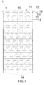
- FIG. 1 is a front view of a rolling-door-type load regulating device according to this invention.
- FIG. 2 is a partial enlarged view of FIG. 1 .
- FIG. 3 is a side view of FIG. 1 .
- FIG. 4 is a partial enlarged view of FIG. 3 .
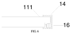
- FIG. 5 is a bottom view of FIG. 1 .
- FIG. 6 is a partial enlarged view of FIG. 5 . Please refer to FIG. 1 to FIG. 6 together.
- the rolling-door-type load regulating device 1 includes a water guiding unit 11, a roller spindle 12, and a driver 13.
- the water guiding unit 11 includes at least two water guiding plates 111 connected in parallel. In this embodiment, the number of the water guiding plates 111 is more than two. However, the invention is not limited thereto.
- the number of the water guiding plates 111 is at least two, effectively reducing the length of each water guiding plate 111 along a direction vertical to the horizontal plane and increasing resistance of each water guiding plate 111 against impaction of a water flow. If the length of one water guiding plate 111 along the vertical direction is too long, since the impaction of the water flow is large, the water guiding plate 111 is easily deformed and even broken in the middle.
- the roller spindle 12 is fixed to one end A of the water guiding unit 11.
- the driver 13 is connected with the roller spindle 12, and the driver 13 drives the roller spindle 12 to rotate to spread or retract the water guiding unit 11.
- the section of each water guiding plate 111 is curved, that is, each water guiding plate 111 is a curved plate. Therefore, when the roller spindle 12 retracts the water guiding unit 11, the water guiding plates 111 can further fit to the roller spindle 12 to reduce space.
- the invention is not limited thereto.
- a direction of an axis of the roller spindle 12 is parallel to the horizontal plane.
- the invention is not limited to.
- the axis of the roller spindle 12 may be vertical to the horizontal plane.
- the position of the roller spindle 12 is not limited either.
- the rolling-door-type load regulating device 1 further includes at least two guiding rails 14, and the two guiding rails 14 are located at the same side of the roller spindle 12 in parallel.
- the roller spindle 12 spreads the water guiding unit 11, two sides of the other end B of the water guiding unit 11 enter into the two guiding rails 14, respectively.
- one water guiding unit 11 corresponds to three guiding rails 14, two of which are disposed at two sides of the water guiding unit 11, and the other guiding rail 14 is disposed in the middle of the water guiding unit 11.
- the number of the guiding rails 14 is not limited in the invention.
- One end A of the water guiding unit 11 is fixed via connection with the roller spindle 12, and the other end B of the water guiding unit 11 is used for limiting position via the guiding rails 14. As two ends of the water guiding unit 11 are positioned, respectively, the water guiding unit 11 can be fully spread to form a "protective screen" to stop or guide the water flow.
- the rolling-door-type load regulating device 1 further includes at least one connecting shaft 15 and at least two rollers 16.
- the at least two water guiding plates 111 are connected via the connecting shaft 15, and the rollers 16 are sleeved on two ends of the connecting shaft 15.
- the number of the connecting shaft 15 is one less than the number of the water guiding plates 111, each connecting shaft 15 corresponds to three rollers 16, and the number of the rollers 16 corresponds to the number of the guiding rails 14.
- the invention is not limited thereto.
- each water guiding plate 111 has holes at two edges and can be concave-convex shaped, respectively, and edges of the adjacent two water guiding plates 111 can match with each other.
- the connecting shaft 15 passes through the holes to connect the water guiding plates 111.
- the water guiding plates 111 are connected through the connecting shaft 15, allowing each water guiding plate 111 to be capable of rotating to change the direction. Therefore, when the water guiding unit 11 is retracted, the water guiding plates 111 can be retracted around the roller spindle 12.
- a plurality of the water guiding plates 111 is nearly located at one line as a whole, further to form the "protective screen" to effectively stop or guide the oncoming water flow.
- the rollers 16 roll along the guiding rails 14 from the top to bottom seen from FIG. 1 , thus to spread the water guiding unit 11.
- the rollers 16 can effectively guide two sides of the other end B of the water guiding unit 11 to enter into the two guiding rails 14, thus to effectively fix the other end B.
- FIG. 7 is a top view of an ocean energy power generating device according to a first embodiment of the invention.
- FIG. 8 is a front view of the ocean energy power generating device according to the first embodiment of the invention (to make the figure more clear, a rolling-door-type load regulating device located at the downstream is not illustrated ). Please refer to FIG. 7 and FIG. 8 together.
- an ocean energy power generating device includes a frame 2, at least one hydraulic turbine 3, at least one electric generator 4, and a rolling-door-type load regulating device 1.
- the at least one hydraulic turbine 3 is disposed in the frame 2.
- the at least one electric generator 4 is connected with the hydraulic turbine 3.
- the rolling-door-type load regulating device 1 includes a water guiding unit 11, a roller spindle 12, and a driver 13.
- the water guiding unit 11 includes at least two water guiding plates 111 connected in parallel.
- the roller spindle 12 is fixed to one end of the water guiding unit 11.
- the driver 13 is connected with the roller spindle 12, and the driver 13 drives the roller spindle 12 to rotate to spread or retract the water guiding unit 11.
- the rolling-door-type load regulating device 1 is disposed at upstream and downstream sides of the hydraulic turbine 3 along a water flow direction D, respectively.
- the rolling-door-type load regulating device 1 further includes at least two guiding rails 14, and the two guiding rails 14 are located at the same side of the roller spindle 12 and are disposed at the frame 2 in parallel.
- the rolling-door-type load regulating device 1 further includes at least one connecting shaft 15 and at least two rollers 16 (as shown in FIG. 1 ).
- the at least two water guiding plates 111 are connected via the connecting shaft 15, and the rollers 16 are sleeved on two ends of the connecting shaft 15.
- the number of the hydraulic turbine 3 is an even number, and two adjacent hydraulic turbines 3 are axially symmetrically arranged so as to allow the two adjacent hydraulic turbines 3 to rotate in opposite directions.
- the bending directions of the blades of the two adjacent hydraulic turbines 3 are axially symmetrical.
- every two hydraulic turbines 3 form a group and are disposed in parallel.
- the hydraulic turbine 3 on the left side rotates in a counter-clockwise direction, while the hydraulic turbine 3 on the right side rotates in a clockwise direction.
- the hydraulic turbines 3 are resistance type hydraulic turbines. Take the left-most hydraulic turbine 3 in FIG. 7 for example.
- the water flow flowing towards a motivation side (the right-hand side in FIG. 7 ) of the hydraulic turbine 3 can rush to a concave portion of an impeller, thereby driving the hydraulic turbine 3 to rotate counterclockwise, while the water flow flowing towards a resistance side (the left-hand side in FIG. 7 ) of the hydraulic turbine 3 can drive the impeller to rotate in the opposite direction.
- the water flow flowing towards the left side of the hydraulic turbine 3 will cause a resistance.
- the angle between the water guiding plates 111 and the water flow direction D is larger than zero degree and smaller than 90 degrees.
- the rolling-door-type load regulating device 1 in the invention can not only stop the water flow but also guide the water flow.
- the driver 13 drives the roller spindle 12 to totally retract the downstream water guiding plates 111, and the upstream water guiding plates 111 are totally spread to form a protective screen, thus to effectively stop the water flow flowing to the resistance side of the hydraulic turbine 3, and to guide the upstream water flow totally to the motivation side of the hydraulic turbine 3. That is, the water flow is guided to a direction vertical to the concave portion of the blade of the hydraulic turbine 3, thereby increasing impaction of the water flow to the hydraulic turbine 3, improving the rotation of the hydraulic turbine 3, and improving the generating power of the electric generator 4.
- the driver 13 drives the roller spindle 12 to retract the upstream water guiding plates 111 and partly spread the downstream water guiding plates 111, and the water flow is allowed to flow into the resistance side of the hydraulic turbine 3, thereby effectively slowing the excessively fast rotation of the hydraulic turbine 3, thus to stabilize the generating power.
- FIG. 9 is a top view of an ocean energy power generating device according to a second embodiment of the invention.
- FIG. 10 is a front view of the ocean energy power generating device according to the second embodiment of the invention. Please refer to FIG. 9 and FIG. 10 together.
- an ocean energy power generating device includes a frame 2, at least one hydraulic turbine 3', at least one electric generator 4, and a rolling-door-type load regulating device 1.
- the same element is numbered with the same reference number.
- the main difference between the second embodiment and the first embodiment lies in that the angle between the water guiding plates 111 and the water flow direction D is equal to 90 degrees, and the hydraulic turbine 3' can be horizontal-axis hydraulic turbine and can be vertical-axis hydraulic turbine.
- All the blades of the hydraulic turbine 3' in the second embodiment bear force.
- the driver 13 can drive the roller spindle 12 to retract the downstream water guiding plates 111 and to spread the upstream water guiding plates 111, thereby forming the protective screen to effectively stop the water flow flowing to the hydraulic turbine 3'.
- the generating power can be prevented from increasing sharply and being unstable, and the problem that the generating power cannot be output directly can be solved.
- the roller spindle 12 can retract the water guiding plates 111 such that all the water flows can flow to the hydraulic turbine 3'.
- the rolling-door-type load regulating device in the invention can regulate the load suffered by the hydraulic turbines. Therefore, the power generated by the ocean energy power generating device can be stably output and be directly used, thereby solving the problem that the output power of the conventional ocean energy power generator has wide fluctuations and poor stability.
- the rolling-door-type load regulating device retract the upstream guiding plates and spread a part of the downstream guiding plates to lower the output load of the hydraulic turbines when the speed of the water flow is too large, but also the regulating device can spread all the upstream water guiding plates to effectively guide the water flow to flow towards the direction vertical to the concave portion of the blade of the hydraulic turbine when the speed of water flow is small, thereby increasing the impact force of the water flow exerted to the hydraulic turbine and improving the rotation of the hydraulic turbine, and improving the generating power.
Landscapes
- Engineering & Computer Science (AREA)
- Mechanical Engineering (AREA)
- Chemical & Material Sciences (AREA)
- Combustion & Propulsion (AREA)
- General Engineering & Computer Science (AREA)
- Structural Engineering (AREA)
- Architecture (AREA)
- Civil Engineering (AREA)
- Oceanography (AREA)
- General Life Sciences & Earth Sciences (AREA)
- Life Sciences & Earth Sciences (AREA)
- Power Engineering (AREA)
- Other Liquid Machine Or Engine Such As Wave Power Use (AREA)
- Hydraulic Turbines (AREA)
Applications Claiming Priority (2)
| Application Number | Priority Date | Filing Date | Title |
|---|---|---|---|
| CN201410005969 | 2014-01-03 | ||
| PCT/CN2014/072878 WO2015100851A1 (fr) | 2014-01-03 | 2014-03-04 | Appareil de régulation de charge de type à volet roulant et appareil à générateur électrique d'énergie marine appliquant celui-ci |
Publications (3)
| Publication Number | Publication Date |
|---|---|
| EP3096002A1 true EP3096002A1 (fr) | 2016-11-23 |
| EP3096002A4 EP3096002A4 (fr) | 2017-03-08 |
| EP3096002B1 EP3096002B1 (fr) | 2018-10-24 |
Family
ID=51478043
Family Applications (1)
| Application Number | Title | Priority Date | Filing Date |
|---|---|---|---|
| EP14876806.2A Not-in-force EP3096002B1 (fr) | 2014-01-03 | 2014-03-04 | Appareil de régulation de charge de type à volet roulant et appareil à générateur électrique d'énergie marine appliquant celui-ci |
Country Status (8)
| Country | Link |
|---|---|
| US (1) | US10054103B2 (fr) |
| EP (1) | EP3096002B1 (fr) |
| JP (1) | JP6328252B2 (fr) |
| CN (3) | CN104763582B (fr) |
| AU (1) | AU2014375923B2 (fr) |
| CA (1) | CA2959458A1 (fr) |
| PH (1) | PH12016501533A1 (fr) |
| WO (2) | WO2015100851A1 (fr) |
Families Citing this family (10)
| Publication number | Priority date | Publication date | Assignee | Title |
|---|---|---|---|---|
| CN104763582B (zh) * | 2014-01-03 | 2018-01-02 | 杭州林东新能源科技股份有限公司 | 卷帘门式负荷调节装置及其应用的海洋能发电装置 |
| CN106640492A (zh) * | 2017-01-22 | 2017-05-10 | 于保琼 | 一种门闸式水能动力叶轮浮筒发电平台 |
| CN108677905B (zh) * | 2018-06-16 | 2020-12-08 | 平湖市飞天人图文设计有限公司 | 水中油性污染物清除装置及使用方法 |
| EP3935278A1 (fr) | 2019-03-08 | 2022-01-12 | Big Moon Power, Inc. | Systèmes et procédés de production d'énergie hydro-électrique |
| US12326131B2 (en) | 2020-08-12 | 2025-06-10 | Riahmedia Inc. | Systems and methods for harnessing marine hydrokinetic energy |
| CN112963294A (zh) * | 2021-02-25 | 2021-06-15 | 李文明 | 一种海上波浪能利用发电设备 |
| CN113170750B (zh) * | 2021-04-01 | 2022-06-21 | 中交海洋建设开发有限公司 | 半潜式深远海养殖网箱自动挡流网系统 |
| US12085053B2 (en) | 2021-06-22 | 2024-09-10 | Riahmedia Inc. | Systems and methods for power distribution and harnessing of marine hydrokinetic energy |
| CN114134867A (zh) * | 2021-11-26 | 2022-03-04 | 惠州市弘基水利工程有限公司 | 无人灌溉闸门及其使用方法 |
| CN118622563A (zh) * | 2024-06-20 | 2024-09-10 | 哈尔滨工程大学三亚南海创新发展基地 | 一种固定式水平轴水流发电阵列装置 |
Family Cites Families (25)
| Publication number | Priority date | Publication date | Assignee | Title |
|---|---|---|---|---|
| CN1019916C (zh) * | 1987-11-03 | 1993-02-17 | 水利水电科学研究院水力机电研究所 | 帘式闸门 |
| FR2703726B1 (fr) * | 1993-04-05 | 1995-06-02 | Plumer Sa | Volet roulant motorisé comprenant des moyens délivrant un signal électrique représentatif du déplacement du tablier. |
| CN2221092Y (zh) | 1994-11-21 | 1996-02-28 | 杨兴尧 | 空腹水冷防火卷帘门 |
| JP3770788B2 (ja) | 2000-11-09 | 2006-04-26 | アイセル株式会社 | シャッタ |
| CN1388300A (zh) | 2001-05-30 | 2003-01-01 | 深圳市中延实业有限公司 | 双帘面水平卷帘门 |
| US6856036B2 (en) * | 2001-06-26 | 2005-02-15 | Sidney Irving Belinsky | Installation for harvesting ocean currents (IHOC) |
| AU2003256485A1 (en) * | 2002-07-11 | 2004-02-02 | Yu-Si Fok | Wave energy conversion device for desalination, etc. |
| JP2004068638A (ja) * | 2002-08-02 | 2004-03-04 | Mitsubishi Heavy Ind Ltd | 海流発電装置 |
| JP4705086B2 (ja) * | 2007-11-06 | 2011-06-22 | 通博 大江 | 水力発電装置 |
| JP4856134B2 (ja) * | 2008-07-30 | 2012-01-18 | 通博 大江 | 水力発電装置 |
| CN102388187A (zh) * | 2009-03-11 | 2012-03-21 | 吉宝岸外与海事科技中心私人有限公司 | 提取潮汐能的装置和系统 |
| CN201474858U (zh) * | 2009-08-07 | 2010-05-19 | 连志敏 | 海上垂直轴可升降复合式发电平台 |
| JP2012082570A (ja) | 2010-10-06 | 2012-04-26 | Zeniya Kaiyo Service Kk | 折り畳み扉式通船ゲート |
| KR101226719B1 (ko) * | 2010-10-25 | 2013-01-25 | 한국해양과학기술원 | 부유식 조류발전장치 및 그 시공방법 |
| EP2659132A1 (fr) * | 2010-12-29 | 2013-11-06 | Organoworld Inc. | Turbine hydraulique améliorée dotée de panneaux muraux rétractables et de déflecteurs aérodynamiques |
| JP4817471B1 (ja) * | 2011-05-18 | 2011-11-16 | 裕二 海野 | 水力発電装置 |
| NL1038868C2 (nl) * | 2011-06-10 | 2012-12-11 | Cornelis Elizabeth Rijlaarsdam | Waterkering voor een doorgang. |
| CN102536599B (zh) * | 2011-12-31 | 2015-03-18 | 李殿海 | 水下涡轮发电机 |
| CN203230523U (zh) * | 2012-08-01 | 2013-10-09 | 杭州林黄丁新能源科技有限公司 | 立式海洋能发电装置 |
| CN203230524U (zh) * | 2013-03-08 | 2013-10-09 | 杭州林黄丁新能源科技有限公司 | 拦网式立式海洋能发电装置 |
| CN203230521U (zh) * | 2013-03-08 | 2013-10-09 | 杭州林黄丁新能源科技有限公司 | 用于海洋能发电机的导水板装置及采用该装置的海洋能发电机 |
| CN203320486U (zh) * | 2013-07-05 | 2013-12-04 | 张志勇 | 一种河道防汛拦污装置 |
| CN103410420B (zh) * | 2013-07-24 | 2015-10-28 | 中铁第四勘察设计院集团有限公司 | 一种多工位卷闸式升降自动防淹挡板结构 |
| CN104763582B (zh) * | 2014-01-03 | 2018-01-02 | 杭州林东新能源科技股份有限公司 | 卷帘门式负荷调节装置及其应用的海洋能发电装置 |
| CN203822535U (zh) * | 2014-01-03 | 2014-09-10 | 杭州林黄丁新能源研究院有限公司 | 卷帘门式负荷调节装置及其应用的海洋能发电装置 |
-
2014
- 2014-02-13 CN CN201410050403.7A patent/CN104763582B/zh active Active
- 2014-03-04 WO PCT/CN2014/072878 patent/WO2015100851A1/fr not_active Ceased
- 2014-03-04 CN CN201410075971.2A patent/CN104763579B/zh active Active
- 2014-03-04 US US15/109,783 patent/US10054103B2/en not_active Expired - Fee Related
- 2014-03-04 AU AU2014375923A patent/AU2014375923B2/en not_active Ceased
- 2014-03-04 JP JP2016544522A patent/JP6328252B2/ja not_active Expired - Fee Related
- 2014-03-04 CA CA2959458A patent/CA2959458A1/fr not_active Abandoned
- 2014-03-04 WO PCT/CN2014/072876 patent/WO2015100850A1/fr not_active Ceased
- 2014-03-04 EP EP14876806.2A patent/EP3096002B1/fr not_active Not-in-force
- 2014-03-04 CN CN201420095813.9U patent/CN203822533U/zh not_active Withdrawn - After Issue
-
2016
- 2016-08-03 PH PH12016501533A patent/PH12016501533A1/en unknown
Also Published As
| Publication number | Publication date |
|---|---|
| WO2015100850A1 (fr) | 2015-07-09 |
| CN104763579B (zh) | 2018-05-22 |
| CN104763579A (zh) | 2015-07-08 |
| US10054103B2 (en) | 2018-08-21 |
| EP3096002B1 (fr) | 2018-10-24 |
| JP6328252B2 (ja) | 2018-05-23 |
| PH12016501533A1 (en) | 2017-02-06 |
| CA2959458A1 (fr) | 2015-07-09 |
| AU2014375923B2 (en) | 2017-11-23 |
| WO2015100851A1 (fr) | 2015-07-09 |
| EP3096002A4 (fr) | 2017-03-08 |
| AU2014375923A1 (en) | 2016-08-18 |
| CN104763582A (zh) | 2015-07-08 |
| CN104763582B (zh) | 2018-01-02 |
| JP2017501338A (ja) | 2017-01-12 |
| CN203822533U (zh) | 2014-09-10 |
| US20160333845A1 (en) | 2016-11-17 |
Similar Documents
| Publication | Publication Date | Title |
|---|---|---|
| US10054103B2 (en) | Rolling-door-type load regulating device and ocean energy power generating device using the same | |
| US9765752B2 (en) | Modularized ocean energy generating device | |
| CN206054171U (zh) | 模块化双向潮流能发电装置 | |
| CN103206331A (zh) | 一种低水头高效轴伸贯流式水泵水轮机及其叶片 | |
| CN103925154B (zh) | 适于风力发电或风力泵浦设备的高效导风装置 | |
| CN103742337B (zh) | 一种设有椭圆形流道的双侧导叶贯流式水轮机 | |
| CN103233846A (zh) | 低水头竖井贯流双向高效水轮机转轮及其机电装置和配套流道 | |
| CN105484930A (zh) | 一种阻力型水轮机及水力发电系统 | |
| CN103321825A (zh) | 一种叶片姿势可变的潮流能获能水轮机 | |
| CN204402744U (zh) | 一种流水型发电装置 | |
| CN109441691B (zh) | 一种尾水管带整流板混流式水轮机 | |
| CN102003326B (zh) | 一种垂直轴菱形流体动能发电转换装置 | |
| CN203230521U (zh) | 用于海洋能发电机的导水板装置及采用该装置的海洋能发电机 | |
| CN103925166A (zh) | 一种风力发电风源增强装置 | |
| CN104763580A (zh) | 可调节负荷的潮流能发电装置 | |
| US9206573B2 (en) | Water flow regulating device and ocean power generating device using the same | |
| CN203230525U (zh) | 海洋能发电装置及其框架 | |
| CN204402748U (zh) | 一种应用于水流落差较小区域的水力发电设备 | |
| WO2017181433A1 (fr) | Générateur à courant de marée et son capot de guidage de courant | |
| CN203822535U (zh) | 卷帘门式负荷调节装置及其应用的海洋能发电装置 | |
| CN203548053U (zh) | 水流负荷调节装置及其应用的海洋能发电装置 | |
| CN201874729U (zh) | 一种垂直轴菱形流体动能发电转换装置 | |
| CN206681902U (zh) | 一种江河流叶片可变角水轮发电机组 | |
| CN206860368U (zh) | 混合型风力发电机组 | |
| CN104343619A (zh) | 水流调节装置及其应用的海洋能发电装置 |
Legal Events
| Date | Code | Title | Description |
|---|---|---|---|
| PUAI | Public reference made under article 153(3) epc to a published international application that has entered the european phase |
Free format text: ORIGINAL CODE: 0009012 |
|
| 17P | Request for examination filed |
Effective date: 20160803 |
|
| AK | Designated contracting states |
Kind code of ref document: A1 Designated state(s): AL AT BE BG CH CY CZ DE DK EE ES FI FR GB GR HR HU IE IS IT LI LT LU LV MC MK MT NL NO PL PT RO RS SE SI SK SM TR |
|
| AX | Request for extension of the european patent |
Extension state: BA ME |
|
| REG | Reference to a national code |
Ref country code: DE Ref legal event code: R079 Ref document number: 602014034881 Country of ref document: DE Free format text: PREVIOUS MAIN CLASS: F03B0015000000 Ipc: F03B0017060000 |
|
| A4 | Supplementary search report drawn up and despatched |
Effective date: 20170207 |
|
| RIC1 | Information provided on ipc code assigned before grant |
Ipc: F03B 17/06 20060101AFI20170201BHEP Ipc: F03B 11/02 20060101ALI20170201BHEP Ipc: F03B 15/04 20060101ALI20170201BHEP Ipc: F03B 13/26 20060101ALI20170201BHEP |
|
| DAX | Request for extension of the european patent (deleted) | ||
| GRAP | Despatch of communication of intention to grant a patent |
Free format text: ORIGINAL CODE: EPIDOSNIGR1 |
|
| STAA | Information on the status of an ep patent application or granted ep patent |
Free format text: STATUS: GRANT OF PATENT IS INTENDED |
|
| INTG | Intention to grant announced |
Effective date: 20180508 |
|
| GRAS | Grant fee paid |
Free format text: ORIGINAL CODE: EPIDOSNIGR3 |
|
| GRAA | (expected) grant |
Free format text: ORIGINAL CODE: 0009210 |
|
| STAA | Information on the status of an ep patent application or granted ep patent |
Free format text: STATUS: THE PATENT HAS BEEN GRANTED |
|
| AK | Designated contracting states |
Kind code of ref document: B1 Designated state(s): AL AT BE BG CH CY CZ DE DK EE ES FI FR GB GR HR HU IE IS IT LI LT LU LV MC MK MT NL NO PL PT RO RS SE SI SK SM TR |
|
| REG | Reference to a national code |
Ref country code: CH Ref legal event code: EP |
|
| REG | Reference to a national code |
Ref country code: IE Ref legal event code: FG4D |
|
| REG | Reference to a national code |
Ref country code: AT Ref legal event code: REF Ref document number: 1056959 Country of ref document: AT Kind code of ref document: T Effective date: 20181115 |
|
| REG | Reference to a national code |
Ref country code: DE Ref legal event code: R096 Ref document number: 602014034881 Country of ref document: DE |
|
| REG | Reference to a national code |
Ref country code: NL Ref legal event code: MP Effective date: 20181024 |
|
| REG | Reference to a national code |
Ref country code: LT Ref legal event code: MG4D |
|
| REG | Reference to a national code |
Ref country code: AT Ref legal event code: MK05 Ref document number: 1056959 Country of ref document: AT Kind code of ref document: T Effective date: 20181024 |
|
| PG25 | Lapsed in a contracting state [announced via postgrant information from national office to epo] |
Ref country code: NL Free format text: LAPSE BECAUSE OF FAILURE TO SUBMIT A TRANSLATION OF THE DESCRIPTION OR TO PAY THE FEE WITHIN THE PRESCRIBED TIME-LIMIT Effective date: 20181024 |
|
| PG25 | Lapsed in a contracting state [announced via postgrant information from national office to epo] |
Ref country code: AT Free format text: LAPSE BECAUSE OF FAILURE TO SUBMIT A TRANSLATION OF THE DESCRIPTION OR TO PAY THE FEE WITHIN THE PRESCRIBED TIME-LIMIT Effective date: 20181024 Ref country code: LV Free format text: LAPSE BECAUSE OF FAILURE TO SUBMIT A TRANSLATION OF THE DESCRIPTION OR TO PAY THE FEE WITHIN THE PRESCRIBED TIME-LIMIT Effective date: 20181024 Ref country code: ES Free format text: LAPSE BECAUSE OF FAILURE TO SUBMIT A TRANSLATION OF THE DESCRIPTION OR TO PAY THE FEE WITHIN THE PRESCRIBED TIME-LIMIT Effective date: 20181024 Ref country code: LT Free format text: LAPSE BECAUSE OF FAILURE TO SUBMIT A TRANSLATION OF THE DESCRIPTION OR TO PAY THE FEE WITHIN THE PRESCRIBED TIME-LIMIT Effective date: 20181024 Ref country code: NO Free format text: LAPSE BECAUSE OF FAILURE TO SUBMIT A TRANSLATION OF THE DESCRIPTION OR TO PAY THE FEE WITHIN THE PRESCRIBED TIME-LIMIT Effective date: 20190124 Ref country code: IS Free format text: LAPSE BECAUSE OF FAILURE TO SUBMIT A TRANSLATION OF THE DESCRIPTION OR TO PAY THE FEE WITHIN THE PRESCRIBED TIME-LIMIT Effective date: 20190224 Ref country code: FI Free format text: LAPSE BECAUSE OF FAILURE TO SUBMIT A TRANSLATION OF THE DESCRIPTION OR TO PAY THE FEE WITHIN THE PRESCRIBED TIME-LIMIT Effective date: 20181024 Ref country code: BG Free format text: LAPSE BECAUSE OF FAILURE TO SUBMIT A TRANSLATION OF THE DESCRIPTION OR TO PAY THE FEE WITHIN THE PRESCRIBED TIME-LIMIT Effective date: 20190124 Ref country code: PL Free format text: LAPSE BECAUSE OF FAILURE TO SUBMIT A TRANSLATION OF THE DESCRIPTION OR TO PAY THE FEE WITHIN THE PRESCRIBED TIME-LIMIT Effective date: 20181024 Ref country code: HR Free format text: LAPSE BECAUSE OF FAILURE TO SUBMIT A TRANSLATION OF THE DESCRIPTION OR TO PAY THE FEE WITHIN THE PRESCRIBED TIME-LIMIT Effective date: 20181024 |
|
| PG25 | Lapsed in a contracting state [announced via postgrant information from national office to epo] |
Ref country code: GR Free format text: LAPSE BECAUSE OF FAILURE TO SUBMIT A TRANSLATION OF THE DESCRIPTION OR TO PAY THE FEE WITHIN THE PRESCRIBED TIME-LIMIT Effective date: 20190125 Ref country code: SE Free format text: LAPSE BECAUSE OF FAILURE TO SUBMIT A TRANSLATION OF THE DESCRIPTION OR TO PAY THE FEE WITHIN THE PRESCRIBED TIME-LIMIT Effective date: 20181024 Ref country code: PT Free format text: LAPSE BECAUSE OF FAILURE TO SUBMIT A TRANSLATION OF THE DESCRIPTION OR TO PAY THE FEE WITHIN THE PRESCRIBED TIME-LIMIT Effective date: 20190224 Ref country code: AL Free format text: LAPSE BECAUSE OF FAILURE TO SUBMIT A TRANSLATION OF THE DESCRIPTION OR TO PAY THE FEE WITHIN THE PRESCRIBED TIME-LIMIT Effective date: 20181024 Ref country code: RS Free format text: LAPSE BECAUSE OF FAILURE TO SUBMIT A TRANSLATION OF THE DESCRIPTION OR TO PAY THE FEE WITHIN THE PRESCRIBED TIME-LIMIT Effective date: 20181024 |
|
| REG | Reference to a national code |
Ref country code: DE Ref legal event code: R097 Ref document number: 602014034881 Country of ref document: DE |
|
| PG25 | Lapsed in a contracting state [announced via postgrant information from national office to epo] |
Ref country code: DK Free format text: LAPSE BECAUSE OF FAILURE TO SUBMIT A TRANSLATION OF THE DESCRIPTION OR TO PAY THE FEE WITHIN THE PRESCRIBED TIME-LIMIT Effective date: 20181024 Ref country code: CZ Free format text: LAPSE BECAUSE OF FAILURE TO SUBMIT A TRANSLATION OF THE DESCRIPTION OR TO PAY THE FEE WITHIN THE PRESCRIBED TIME-LIMIT Effective date: 20181024 Ref country code: IT Free format text: LAPSE BECAUSE OF FAILURE TO SUBMIT A TRANSLATION OF THE DESCRIPTION OR TO PAY THE FEE WITHIN THE PRESCRIBED TIME-LIMIT Effective date: 20181024 |
|
| PG25 | Lapsed in a contracting state [announced via postgrant information from national office to epo] |
Ref country code: RO Free format text: LAPSE BECAUSE OF FAILURE TO SUBMIT A TRANSLATION OF THE DESCRIPTION OR TO PAY THE FEE WITHIN THE PRESCRIBED TIME-LIMIT Effective date: 20181024 Ref country code: SM Free format text: LAPSE BECAUSE OF FAILURE TO SUBMIT A TRANSLATION OF THE DESCRIPTION OR TO PAY THE FEE WITHIN THE PRESCRIBED TIME-LIMIT Effective date: 20181024 Ref country code: EE Free format text: LAPSE BECAUSE OF FAILURE TO SUBMIT A TRANSLATION OF THE DESCRIPTION OR TO PAY THE FEE WITHIN THE PRESCRIBED TIME-LIMIT Effective date: 20181024 Ref country code: SK Free format text: LAPSE BECAUSE OF FAILURE TO SUBMIT A TRANSLATION OF THE DESCRIPTION OR TO PAY THE FEE WITHIN THE PRESCRIBED TIME-LIMIT Effective date: 20181024 |
|
| PLBE | No opposition filed within time limit |
Free format text: ORIGINAL CODE: 0009261 |
|
| STAA | Information on the status of an ep patent application or granted ep patent |
Free format text: STATUS: NO OPPOSITION FILED WITHIN TIME LIMIT |
|
| REG | Reference to a national code |
Ref country code: DE Ref legal event code: R119 Ref document number: 602014034881 Country of ref document: DE |
|
| 26N | No opposition filed |
Effective date: 20190725 |
|
| PG25 | Lapsed in a contracting state [announced via postgrant information from national office to epo] |
Ref country code: MC Free format text: LAPSE BECAUSE OF FAILURE TO SUBMIT A TRANSLATION OF THE DESCRIPTION OR TO PAY THE FEE WITHIN THE PRESCRIBED TIME-LIMIT Effective date: 20181024 Ref country code: SI Free format text: LAPSE BECAUSE OF FAILURE TO SUBMIT A TRANSLATION OF THE DESCRIPTION OR TO PAY THE FEE WITHIN THE PRESCRIBED TIME-LIMIT Effective date: 20181024 |
|
| REG | Reference to a national code |
Ref country code: CH Ref legal event code: PL |
|
| GBPC | Gb: european patent ceased through non-payment of renewal fee |
Effective date: 20190304 |
|
| PG25 | Lapsed in a contracting state [announced via postgrant information from national office to epo] |
Ref country code: LU Free format text: LAPSE BECAUSE OF NON-PAYMENT OF DUE FEES Effective date: 20190304 |
|
| REG | Reference to a national code |
Ref country code: BE Ref legal event code: MM Effective date: 20190331 |
|
| PG25 | Lapsed in a contracting state [announced via postgrant information from national office to epo] |
Ref country code: DE Free format text: LAPSE BECAUSE OF NON-PAYMENT OF DUE FEES Effective date: 20191001 Ref country code: CH Free format text: LAPSE BECAUSE OF NON-PAYMENT OF DUE FEES Effective date: 20190331 Ref country code: IE Free format text: LAPSE BECAUSE OF NON-PAYMENT OF DUE FEES Effective date: 20190304 Ref country code: LI Free format text: LAPSE BECAUSE OF NON-PAYMENT OF DUE FEES Effective date: 20190331 Ref country code: GB Free format text: LAPSE BECAUSE OF NON-PAYMENT OF DUE FEES Effective date: 20190304 |
|
| PG25 | Lapsed in a contracting state [announced via postgrant information from national office to epo] |
Ref country code: FR Free format text: LAPSE BECAUSE OF NON-PAYMENT OF DUE FEES Effective date: 20190331 Ref country code: BE Free format text: LAPSE BECAUSE OF NON-PAYMENT OF DUE FEES Effective date: 20190331 |
|
| PG25 | Lapsed in a contracting state [announced via postgrant information from national office to epo] |
Ref country code: TR Free format text: LAPSE BECAUSE OF FAILURE TO SUBMIT A TRANSLATION OF THE DESCRIPTION OR TO PAY THE FEE WITHIN THE PRESCRIBED TIME-LIMIT Effective date: 20181024 |
|
| PG25 | Lapsed in a contracting state [announced via postgrant information from national office to epo] |
Ref country code: MT Free format text: LAPSE BECAUSE OF NON-PAYMENT OF DUE FEES Effective date: 20190304 |
|
| PG25 | Lapsed in a contracting state [announced via postgrant information from national office to epo] |
Ref country code: CY Free format text: LAPSE BECAUSE OF FAILURE TO SUBMIT A TRANSLATION OF THE DESCRIPTION OR TO PAY THE FEE WITHIN THE PRESCRIBED TIME-LIMIT Effective date: 20181024 |
|
| PG25 | Lapsed in a contracting state [announced via postgrant information from national office to epo] |
Ref country code: HU Free format text: LAPSE BECAUSE OF FAILURE TO SUBMIT A TRANSLATION OF THE DESCRIPTION OR TO PAY THE FEE WITHIN THE PRESCRIBED TIME-LIMIT; INVALID AB INITIO Effective date: 20140304 |
|
| PG25 | Lapsed in a contracting state [announced via postgrant information from national office to epo] |
Ref country code: MK Free format text: LAPSE BECAUSE OF FAILURE TO SUBMIT A TRANSLATION OF THE DESCRIPTION OR TO PAY THE FEE WITHIN THE PRESCRIBED TIME-LIMIT Effective date: 20181024 |