EP3096011A1 - Dispositif de distribution de liquide et système de refroidissement de liquide - Google Patents
Dispositif de distribution de liquide et système de refroidissement de liquide Download PDFInfo
- Publication number
- EP3096011A1 EP3096011A1 EP16168889.0A EP16168889A EP3096011A1 EP 3096011 A1 EP3096011 A1 EP 3096011A1 EP 16168889 A EP16168889 A EP 16168889A EP 3096011 A1 EP3096011 A1 EP 3096011A1
- Authority
- EP
- European Patent Office
- Prior art keywords
- liquid
- magnetic area
- magnetic
- supply device
- liquid supply
- Prior art date
- Legal status (The legal status is an assumption and is not a legal conclusion. Google has not performed a legal analysis and makes no representation as to the accuracy of the status listed.)
- Withdrawn
Links
Images





Classifications
-
- F—MECHANICAL ENGINEERING; LIGHTING; HEATING; WEAPONS; BLASTING
- F04—POSITIVE - DISPLACEMENT MACHINES FOR LIQUIDS; PUMPS FOR LIQUIDS OR ELASTIC FLUIDS
- F04B—POSITIVE-DISPLACEMENT MACHINES FOR LIQUIDS; PUMPS
- F04B53/00—Component parts, details or accessories not provided for in, or of interest apart from, groups F04B1/00 - F04B23/00 or F04B39/00 - F04B47/00
- F04B53/16—Casings; Cylinders; Cylinder liners or heads; Fluid connections
-
- F—MECHANICAL ENGINEERING; LIGHTING; HEATING; WEAPONS; BLASTING
- F04—POSITIVE - DISPLACEMENT MACHINES FOR LIQUIDS; PUMPS FOR LIQUIDS OR ELASTIC FLUIDS
- F04B—POSITIVE-DISPLACEMENT MACHINES FOR LIQUIDS; PUMPS
- F04B11/00—Equalisation of pulses, e.g. by use of air vessels; Counteracting cavitation
- F04B11/0008—Equalisation of pulses, e.g. by use of air vessels; Counteracting cavitation using accumulators
-
- F—MECHANICAL ENGINEERING; LIGHTING; HEATING; WEAPONS; BLASTING
- F04—POSITIVE - DISPLACEMENT MACHINES FOR LIQUIDS; PUMPS FOR LIQUIDS OR ELASTIC FLUIDS
- F04B—POSITIVE-DISPLACEMENT MACHINES FOR LIQUIDS; PUMPS
- F04B11/00—Equalisation of pulses, e.g. by use of air vessels; Counteracting cavitation
- F04B11/0008—Equalisation of pulses, e.g. by use of air vessels; Counteracting cavitation using accumulators
- F04B11/0033—Equalisation of pulses, e.g. by use of air vessels; Counteracting cavitation using accumulators with a mechanical spring
-
- F—MECHANICAL ENGINEERING; LIGHTING; HEATING; WEAPONS; BLASTING
- F04—POSITIVE - DISPLACEMENT MACHINES FOR LIQUIDS; PUMPS FOR LIQUIDS OR ELASTIC FLUIDS
- F04B—POSITIVE-DISPLACEMENT MACHINES FOR LIQUIDS; PUMPS
- F04B17/00—Pumps characterised by combination with, or adaptation to, specific driving engines or motors
- F04B17/03—Pumps characterised by combination with, or adaptation to, specific driving engines or motors driven by electric motors
- F04B17/04—Pumps characterised by combination with, or adaptation to, specific driving engines or motors driven by electric motors using solenoids
-
- F—MECHANICAL ENGINEERING; LIGHTING; HEATING; WEAPONS; BLASTING
- F04—POSITIVE - DISPLACEMENT MACHINES FOR LIQUIDS; PUMPS FOR LIQUIDS OR ELASTIC FLUIDS
- F04B—POSITIVE-DISPLACEMENT MACHINES FOR LIQUIDS; PUMPS
- F04B19/00—Machines or pumps having pertinent characteristics not provided for in, or of interest apart from, groups F04B1/00 - F04B17/00
- F04B19/20—Other positive-displacement pumps
- F04B19/22—Other positive-displacement pumps of reciprocating-piston type
-
- F—MECHANICAL ENGINEERING; LIGHTING; HEATING; WEAPONS; BLASTING
- F04—POSITIVE - DISPLACEMENT MACHINES FOR LIQUIDS; PUMPS FOR LIQUIDS OR ELASTIC FLUIDS
- F04B—POSITIVE-DISPLACEMENT MACHINES FOR LIQUIDS; PUMPS
- F04B23/00—Pumping installations or systems
- F04B23/02—Pumping installations or systems having reservoirs
-
- F—MECHANICAL ENGINEERING; LIGHTING; HEATING; WEAPONS; BLASTING
- F04—POSITIVE - DISPLACEMENT MACHINES FOR LIQUIDS; PUMPS FOR LIQUIDS OR ELASTIC FLUIDS
- F04B—POSITIVE-DISPLACEMENT MACHINES FOR LIQUIDS; PUMPS
- F04B53/00—Component parts, details or accessories not provided for in, or of interest apart from, groups F04B1/00 - F04B23/00 or F04B39/00 - F04B47/00
- F04B53/08—Cooling; Heating; Preventing freezing
-
- F—MECHANICAL ENGINEERING; LIGHTING; HEATING; WEAPONS; BLASTING
- F04—POSITIVE - DISPLACEMENT MACHINES FOR LIQUIDS; PUMPS FOR LIQUIDS OR ELASTIC FLUIDS
- F04B—POSITIVE-DISPLACEMENT MACHINES FOR LIQUIDS; PUMPS
- F04B53/00—Component parts, details or accessories not provided for in, or of interest apart from, groups F04B1/00 - F04B23/00 or F04B39/00 - F04B47/00
- F04B53/14—Pistons, piston-rods or piston-rod connections
-
- F—MECHANICAL ENGINEERING; LIGHTING; HEATING; WEAPONS; BLASTING
- F28—HEAT EXCHANGE IN GENERAL
- F28D—HEAT-EXCHANGE APPARATUS, NOT PROVIDED FOR IN ANOTHER SUBCLASS, IN WHICH THE HEAT-EXCHANGE MEDIA DO NOT COME INTO DIRECT CONTACT
- F28D15/00—Heat-exchange apparatus with the intermediate heat-transfer medium in closed tubes passing into or through the conduit walls ; Heat-exchange apparatus employing intermediate heat-transfer medium or bodies
-
- H—ELECTRICITY
- H10—SEMICONDUCTOR DEVICES; ELECTRIC SOLID-STATE DEVICES NOT OTHERWISE PROVIDED FOR
- H10W—GENERIC PACKAGES, INTERCONNECTIONS, CONNECTORS OR OTHER CONSTRUCTIONAL DETAILS OF DEVICES COVERED BY CLASS H10
- H10W40/00—Arrangements for thermal protection or thermal control
- H10W40/40—Arrangements for thermal protection or thermal control involving heat exchange by flowing fluids
- H10W40/47—Arrangements for thermal protection or thermal control involving heat exchange by flowing fluids by flowing liquids, e.g. forced water cooling
-
- F—MECHANICAL ENGINEERING; LIGHTING; HEATING; WEAPONS; BLASTING
- F28—HEAT EXCHANGE IN GENERAL
- F28D—HEAT-EXCHANGE APPARATUS, NOT PROVIDED FOR IN ANOTHER SUBCLASS, IN WHICH THE HEAT-EXCHANGE MEDIA DO NOT COME INTO DIRECT CONTACT
- F28D21/00—Heat-exchange apparatus not covered by any of the groups F28D1/00 - F28D20/00
- F28D2021/0019—Other heat exchangers for particular applications; Heat exchange systems not otherwise provided for
- F28D2021/0028—Other heat exchangers for particular applications; Heat exchange systems not otherwise provided for for cooling heat generating elements, e.g. for cooling electronic components or electric devices
-
- F—MECHANICAL ENGINEERING; LIGHTING; HEATING; WEAPONS; BLASTING
- F28—HEAT EXCHANGE IN GENERAL
- F28D—HEAT-EXCHANGE APPARATUS, NOT PROVIDED FOR IN ANOTHER SUBCLASS, IN WHICH THE HEAT-EXCHANGE MEDIA DO NOT COME INTO DIRECT CONTACT
- F28D21/00—Heat-exchange apparatus not covered by any of the groups F28D1/00 - F28D20/00
- F28D2021/0019—Other heat exchangers for particular applications; Heat exchange systems not otherwise provided for
- F28D2021/0028—Other heat exchangers for particular applications; Heat exchange systems not otherwise provided for for cooling heat generating elements, e.g. for cooling electronic components or electric devices
- F28D2021/0031—Radiators for recooling a coolant of cooling systems
-
- F—MECHANICAL ENGINEERING; LIGHTING; HEATING; WEAPONS; BLASTING
- F28—HEAT EXCHANGE IN GENERAL
- F28F—DETAILS OF HEAT-EXCHANGE AND HEAT-TRANSFER APPARATUS, OF GENERAL APPLICATION
- F28F2250/00—Arrangements for modifying the flow of the heat exchange media, e.g. flow guiding means; Particular flow patterns
- F28F2250/08—Fluid driving means, e.g. pumps, fans
-
- F—MECHANICAL ENGINEERING; LIGHTING; HEATING; WEAPONS; BLASTING
- F28—HEAT EXCHANGE IN GENERAL
- F28F—DETAILS OF HEAT-EXCHANGE AND HEAT-TRANSFER APPARATUS, OF GENERAL APPLICATION
- F28F2265/00—Safety or protection arrangements; Arrangements for preventing malfunction
- F28F2265/10—Safety or protection arrangements; Arrangements for preventing malfunction for preventing overheating, e.g. heat shields
Definitions
- the present invention relates to a liquid supply device and a liquid cooling system, particularly a liquid supply device capable of supplying a cooling liquid to a liquid cooling system in time when the cooling liquid is insufficient.
- a liquid cooling system essentially consists of a liquid cooling head, a radiator, a pump and a liquid storage box connected through a plurality of tubes.
- the pump transports a cooling liquid to the liquid cooling head, the cooling liquid absorbs the heat generated by the electronic component, and then the radiator cools the cooling liquid.
- the cooling liquid will reduce due to vaporization, such that the cooling liquid may be insufficient. If the user does not supply the cooling liquid in time, the liquid cooling system may be damaged due to insufficient cooling liquid.
- the present invention aims at providing a liquid supply device and a liquid cooling system equipped with the liquid supply device, thereby resolving the aforesaid problems.
- the claimed liquid supply device includes a casing, a cover, a plunger and a driving unit.
- the casing has a liquid outlet.
- the cover is connected to the casing.
- a chamber is formed between the casing and the cover. The chamber communicates with the liquid outlet.
- the plunger is movably disposed in the chamber.
- the driving unit is disposed relative to the plunger and used for driving the plunger to move.
- the claimed liquid cooling system includes a liquid cooling head, a radiator, a plurality of tubes and a liquid supply device.
- the tubes are connected between the liquid cooling head and the radiator.
- the liquid supply device is selectively connected to one of the liquid cooling head, the radiator and the tubes.
- the liquid supply device includes a casing, a cover, a plunger and a driving unit.
- the casing has a liquid outlet.
- the cover is connected to the casing.
- a chamber is formed between the casing and the cover. The chamber communicates with the liquid outlet.
- the plunger is movably disposed in the chamber.
- the driving unit is disposed relative to the plunger and used for driving the plunger to move.
- FIG. 1 is a schematic view illustrating a liquid cooling system 1 according to an embodiment of the invention
- FIG. 2 is a schematic view illustrating a liquid cooling system 1' according to another embodiment of the invention
- FIG. 3 is a schematic view illustrating a liquid supply device 20 according to an embodiment of the invention
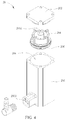
- FIG. 4 is an exploded view illustrating the liquid supply device 20 shown in FIG. 3
- FIG. 5 is an exploded view illustrating the liquid supply device 20 shown in FIG. 3 from another viewing angle
- FIG. 6 is a cross-sectional view illustrating the liquid supply device 20 shown in FIG. 3 along line X-X.
- the liquid cooling system 1 includes a liquid cooling head 10, a radiator 12, a pump 14, a liquid storage box 16 and a plurality of tubes 18.
- the tubes 18 are connected among the liquid cooling head 10, the radiator 12, the pump 14 and the liquid storage box 16 and used for transporting a cooling liquid among the liquid cooling head 10, the radiator 12, the pump 14 and the liquid storage box 16.
- the cooling liquid (not shown in FIG. 1 ) is filled in the liquid cooling head 10, the radiator 12, the pump 14, the liquid storage box 16 and the tubes 18.
- the liquid cooling head 10 of the liquid cooling system 1 is attached on the electronic component.
- the pump 14 transports the cooling liquid to the liquid cooling head 10, the cooling liquid absorbs the heat generated by the electronic component, and then the radiator 12 cools the cooling liquid.
- the liquid cooling system 1' shown in FIG. 2 includes a liquid cooling head 10', a radiator 12 and a plurality of tubes 18.
- the liquid cooling head 10' may function as a pump.
- the pump 14 of the liquid cooling system 1 may be integrated into the liquid cooling head 10' of the liquid cooling system 1'.
- the liquid storage box 16 of the liquid cooling system 1 is omitted.
- the liquid storage box 16 can be integrated with the radiator 12 or the liquid cooling head 10'.
- the liquid cooling system of the invention may be equipped with or not equipped with the liquid storage box 16 according to practical applications.
- the tubes 18 are connected between the liquid cooling head 10' with a pump function and the radiator 12 and used for transporting a cooling liquid between the liquid cooling head 10' and the radiator 12.
- the cooling liquid (not shown in FIG. 1 ) is filled in the liquid cooling head 10', the radiator 12 and the tubes 18.
- the liquid cooling head 10' of the liquid cooling system 1' is attached on the electronic component.
- the cooling liquid of the liquid cooling head 10' absorbs the heat generated by the electronic component and then the radiator 12 cools the cooling liquid.
- the aforesaid liquid cooling system 1 or liquid cooling system 1' further includes a liquid supply device 20, wherein the liquid supply device 20 may be selectively connected to one of the liquid cooling head 10, the radiator 12, the pump 14, the liquid storage box 16 and the tubes 18 shown in FIG. 1 or selectively connected to one of the liquid cooling head 10', the radiator 12 and the tubes 18 shown in FIG. 2 according to practical applications.
- the liquid supply device 20 may have the function of the liquid storage box.
- the liquid supply device 20 includes a casing 200, a cover 202, a plunger 204, a driving unit 205 and a washer 206.
- the casing 200 has a liquid outlet 2000.
- the cover 202 is connected to the casing 200 and a chamber 208 is formed between the casing 200 and the cover 202.
- the chamber 208 communicates with the liquid outlet 2000 and contains a cooling liquid 22.
- the cooling liquid 22 may be water or other liquids.
- the plunger 204 is movably disposed in the chamber 208.
- the washer 206 is sleeved on an outer wall of the plunger 204 and abuts against an inner wall of the casing 200. Accordingly, the washer 206 can prevent the cooling liquid 22 from entering a space between the cover 202 and the plunger 204.
- the liquid outlet 2000 communicates with one of the liquid cooling head 10, 10', the radiator 12, the pump 14, the liquid storage box 16 and the tubes 18, such that the cooling liquid 22 of the chamber 208 can be injected into one of the liquid cooling head 10, 10', the radiator 12, the pump 14, the liquid storage box 16 and the tubes 18 through the liquid outlet 2000.
- the driving unit 205 is disposed relative to the plunger 204 and used for driving the plunger 204 to move.
- the driving unit 205 includes a first magnetic area 2050 and a second magnetic area 2052, wherein the first magnetic area 2050 is disposed on the cover 202, the second magnetic area 2052 is disposed on the plunger 204, and a position of the first magnetic area 2050 is corresponding to a position of the second magnetic area 2052. As shown in FIG.
- a magnetic pole of an end of the first magnetic area 2050 facing the second magnetic area 2052 is identical to a magnetic pole of an end of the second magnetic area 2052 facing the first magnetic area 2050, such that a magnetic repulsive force is generated between the first magnetic area 2050 and the second magnetic area 2052.
- the magnetic pole of an end of the first magnetic area 2050 facing the second magnetic area 2052 and the magnetic pole of an end of the second magnetic area 2052 facing the first magnetic area 2050 both may be north magnetic poles or south magnetic poles according to practical applications.
- the first magnetic area 2050 may be a magnet or an electromagnet
- the second magnetic area 2052 may be a magnet.
- the magnetic repulsive force generated between the first magnetic area 2050 and the second magnetic area 2052 balances with the hydraulic pressure generated by the cooling liquid 22.
- the plunger 204 stays static in the chamber 208.
- the cooling liquid of the liquid cooling system 1,1' reduces and then the hydraulic pressure reduces, the magnetic repulsive force generated between the first magnetic area 2050 and the second magnetic area 2052 will push the plunger 204 to move, so as to inject the cooling liquid 22 from the chamber 208 into one of the liquid cooling head 10, 10', the radiator 12, the pump 14, the liquid storage box 16 and the tubes 18.
- the liquid supply device 20 of the invention can supply the cooling liquid to the liquid cooling system 1,1' automatically when the cooling liquid is insufficient, so as to prevent the liquid cooling system 1, 1' from being damaged due to insufficient cooling liquid.
- the plunger 204 stops moving.
- FIG. 7 is a cross-sectional view illustrating a liquid supply device 20' according to another embodiment of the invention.
- the difference between the liquid supply device 20' and the aforesaid liquid supply device 20 is that the driving unit 205 of the liquid supply device 20' further includes a third magnetic area 2054 and the third magnetic area 2054 is disposed on the casing 200, wherein the second magnetic area 2052 is located between the first magnetic area 2050 and the third magnetic area 2054.
- the driving unit 205 of the liquid supply device 20' further includes a third magnetic area 2054 and the third magnetic area 2054 is disposed on the casing 200, wherein the second magnetic area 2052 is located between the first magnetic area 2050 and the third magnetic area 2054.
- a magnetic pole of an end of the second magnetic area 2052 facing the third magnetic area 2054 is opposite to a magnetic pole of an end of the third magnetic area 2054 facing the second magnetic area 2052, such that a magnetic attraction force is generated between the second magnetic area 2052 and the third magnetic area 2054.
- the magnetic pole of an end of the second magnetic area 2052 facing the third magnetic area 2054 may be a north magnetic pole or a south magnetic pole
- the magnetic pole of an end of the third magnetic area 2054 facing the second magnetic area 2052 may be a south magnetic pole or a north magnetic pole correspondingly according to practical applications.
- the third magnetic area 2054 may be a magnetic induction material (e.g. iron or other metals), a magnet or an electromagnet.
- the magnetic repulsive force generated between the first magnetic area 2050 and the second magnetic area 2052 and the magnetic attraction force generated between the second magnetic area 2052 and the third magnetic area 2054 balance with the hydraulic pressure generated by the cooling liquid 22.
- the plunger 204 stays static in the chamber 208.
- the magnetic repulsive force generated between the first magnetic area 2050 and the second magnetic area 2052 will push the plunger 204 to move and the magnetic attraction force generated between the second magnetic area 2052 and the third magnetic area 2054 will pull the plunger 204 to move, so as to inject the cooling liquid 22 from the chamber 208 into one of the liquid cooling head 10, 10', the radiator 12, the pump 14, the liquid storage box 16 and the tubes 18.
- the plunger 204 stops moving.
- the third magnetic area 2054 may be detachably disposed on a bottom of the casing 200.
- the user may detach the third magnetic area 2054 from the bottom of the casing 200 first, so as to prevent the magnetic attraction force generated between the second magnetic area 2052 and the third magnetic area 2054 from hindering the supply of the cooling liquid 22.
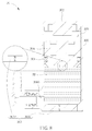
- FIG. 8 is a cross-sectional view illustrating a liquid supply device 30 according to another embodiment of the invention.
- the liquid supply device 30 includes a casing 300, a cover 302, a plunger 304, a driving unit 305 and a washer 306.
- the casing 300 has a liquid outlet 3000.
- the cover 302 is connected to the casing 300 and a chamber 308 is formed between the casing 300 and the cover 302.
- the chamber 308 communicates with the liquid outlet 3000 and contains a cooling liquid 32.
- the cooling liquid 32 may be water or other liquids.
- the plunger 304 is movably disposed in the chamber 308.
- the washer 306 is sleeved on an outer wall of the plunger 304 and abuts against an inner wall of the casing 300. Accordingly, the washer 306 can prevent the cooling liquid 32 from entering a space between the cover 302 and the plunger 304.
- the liquid outlet 3000 communicates with one of the liquid cooling head 10, 10', the radiator 12, the pump 14, the liquid storage box 16 and the tubes 18, such that the cooling liquid 32 of the chamber 308 can be injected into one of the liquid cooling head 10, 10', the radiator 12, the pump 14, the liquid storage box 16 and the tubes 18 through the liquid outlet 3000.
- the driving unit 305 is disposed relative to the plunger 304 and used for driving the plunger 304 to move.
- the driving unit 305 includes a first magnetic area 3050 and a second magnetic area 3052, wherein the first magnetic area 3050 is disposed on the casing 300, the second magnetic area 3052 is disposed on the plunger 304, and a position of the first magnetic area 3050 is corresponding to a position of the second magnetic area 3052.
- a magnetic pole of an end of the first magnetic area 3050 facing the second magnetic area 3052 is opposite to a magnetic pole of an end of the second magnetic area 3052 facing the first magnetic area 3050, such that a magnetic attraction force is generated between the first magnetic area 3050 and the second magnetic area 3052.
- the magnetic pole of an end of the first magnetic area 3050 facing the second magnetic area 3052 may be a north magnetic pole or a south magnetic pole
- the magnetic pole of an end of the second magnetic area 3052 facing the first magnetic area 3050 may be a south magnetic pole or a north magnetic pole correspondingly according to practical applications.
- the first magnetic area 3050 may be a magnetic induction material (e.g. iron or other metals), a magnet or an electromagnet
- the second magnetic area 3052 may be a magnet.
- the magnetic attraction force generated between the first magnetic area 3050 and the second magnetic area 3052 balances with the hydraulic pressure generated by the cooling liquid 32.
- the plunger 304 stays static in the chamber 308.
- the cooling liquid of the liquid cooling system 1,1' reduces and then the hydraulic pressure reduces, the magnetic attraction force generated between the first magnetic area 3050 and the second magnetic area 3052 will pull the plunger 304 to move, so as to inject the cooling liquid 32 from the chamber 308 into one of the liquid cooling head 10, 10', the radiator 12, the pump 14, the liquid storage box 16 and the tubes 18.
- the liquid supply device 30 of the invention can supply the cooling liquid to the liquid cooling system 1,1' automatically when the cooling liquid is insufficient, so as to prevent the liquid cooling system 1, 1' from being damaged due to insufficient cooling liquid.
- the plunger 304 stops moving.
- the first magnetic area 3050 may be detachably disposed on a bottom of the casing 300.
- the user may detach the first magnetic area 3050 from the bottom of the casing 300 first, so as to prevent the magnetic attraction force generated between the first magnetic area 3050 and the second magnetic area 3052 from hindering the supply of the cooling liquid 32.
- FIG. 9 is a cross-sectional view illustrating a liquid supply device 40 according to another embodiment of the invention.
- the liquid supply device 40 replaces the aforesaid driving unit 205 by a driving unit 405.
- the driving unit 405 may be a resilient member (e.g. spring or other resilient objects) and opposite ends of the driving unit 405 abut against the cover 202 and the plunger 204, respectively.
- the liquid outlet 2000 communicates with one of the liquid cooling head 10, 10', the radiator 12, the pump 14, the liquid storage box 16 and the tubes 18, such that the cooling liquid 22 of the chamber 208 can be injected into one of the liquid cooling head 10, 10', the radiator 12, the pump 14, the liquid storage box 16 and the tubes 18 through the liquid outlet 2000.
- FIG. 9 and FIG. 6 are represented by the same numerals, so the repeated explanation will not be depicted herein again.
- the driving unit 405 When the liquid supply device 40 is assembled completely and the chamber 208 contains the cooling liquid 22, the driving unit 405 is compressed. At this time, the driving unit 405 pushes the plunger 204 to move downward in the chamber 208 till the hydraulic pressure of the liquid cooling system 1,1' balances. When the cooling liquid of the liquid cooling system 1,1' reduces and then the hydraulic pressure reduces, the driving unit 405 of the liquid supply device 40 will push the plunger 204 to move, so as to inject the cooling liquid 22 from the chamber 208 into one of the liquid cooling head 10, 10', the radiator 12, the pump 14, the liquid storage box 16 and the tubes 18.
- the liquid supply device 40 of the invention can supply the cooling liquid to the liquid cooling system 1,1' automatically when the cooling liquid is insufficient, so as to prevent the liquid cooling system 1, 1' from being damaged due to insufficient cooling liquid.
- the invention may also replace the driving unit 405 by other mechanisms, which may generate normal force, shearing force, torque or magnetic force, to push the plunger 204 to move, so as to supply the cooling liquid.
- the liquid supply device of the invention is selectively connected to one of the liquid cooling head, the radiator, the pump, the liquid storage box and the tubes.
- the liquid supply device utilizes the driving unit to drive the plunger to move, so as to inject the cooling liquid from the chamber into the liquid cooling system.
- the liquid supply device of the invention can supply the cooling liquid to the liquid cooling system automatically when the cooling liquid is insufficient, so as to prevent the liquid cooling system from being damaged due to insufficient cooling liquid.
Landscapes
- Engineering & Computer Science (AREA)
- Mechanical Engineering (AREA)
- General Engineering & Computer Science (AREA)
- Physics & Mathematics (AREA)
- Thermal Sciences (AREA)
- Cooling Or The Like Of Electrical Apparatus (AREA)
- Microelectronics & Electronic Packaging (AREA)
- Fluid-Damping Devices (AREA)
- Motor Or Generator Cooling System (AREA)
- Details Of Reciprocating Pumps (AREA)
Applications Claiming Priority (2)
| Application Number | Priority Date | Filing Date | Title |
|---|---|---|---|
| CN201520303586.9U CN204578959U (zh) | 2015-05-12 | 2015-05-12 | 液体补充机构及液冷系统 |
| CN201510266823.3A CN106304753A (zh) | 2015-05-22 | 2015-05-22 | 液体补充机构及液冷系统 |
Publications (1)
| Publication Number | Publication Date |
|---|---|
| EP3096011A1 true EP3096011A1 (fr) | 2016-11-23 |
Family
ID=55236185
Family Applications (2)
| Application Number | Title | Priority Date | Filing Date |
|---|---|---|---|
| EP16151592.9A Active EP3104009B1 (fr) | 2015-05-12 | 2016-01-15 | Mécanisme d'alimentation en liquide et système de refroidissement de liquide |
| EP16168889.0A Withdrawn EP3096011A1 (fr) | 2015-05-12 | 2016-05-10 | Dispositif de distribution de liquide et système de refroidissement de liquide |
Family Applications Before (1)
| Application Number | Title | Priority Date | Filing Date |
|---|---|---|---|
| EP16151592.9A Active EP3104009B1 (fr) | 2015-05-12 | 2016-01-15 | Mécanisme d'alimentation en liquide et système de refroidissement de liquide |
Country Status (3)
| Country | Link |
|---|---|
| US (1) | US20160338224A1 (fr) |
| EP (2) | EP3104009B1 (fr) |
| TW (2) | TWM548683U (fr) |
Families Citing this family (4)
| Publication number | Priority date | Publication date | Assignee | Title |
|---|---|---|---|---|
| CN206575730U (zh) * | 2016-08-10 | 2017-10-20 | 讯凯国际股份有限公司 | 液体补充装置及液冷系统 |
| TWI688326B (zh) * | 2018-01-17 | 2020-03-11 | 緯創資通股份有限公司 | 冷卻液補充機構及具有冷卻液補充機構的冷卻循環系統及電子設備 |
| JP7581701B2 (ja) * | 2020-08-21 | 2024-11-13 | ニデック株式会社 | 送液装置 |
| CN115701560B (zh) | 2021-08-02 | 2025-12-09 | 中强光电股份有限公司 | 散热模块与投影装置 |
Citations (9)
| Publication number | Priority date | Publication date | Assignee | Title |
|---|---|---|---|---|
| FR1403456A (fr) * | 1964-07-31 | 1965-06-18 | R I V | Accumulateur d'énergie pneumatique |
| DE10308982B3 (de) * | 2003-03-01 | 2004-03-04 | Ald Vacuum Technologies Ag | Verfahren und Vorrichtung zum Ausgleich der im Schmelzraum und im Kühlwassersystem herrschenden Drücke bei einer Sonderschmelzanlage |
| WO2006087031A1 (fr) * | 2005-02-18 | 2006-08-24 | Ebm-Papst St. Georgen Gmbh & Co. Kg | Echangeur de chaleur |
| DE102007036854A1 (de) * | 2006-08-07 | 2008-02-14 | Eto Magnetic Kg | Hydraulikflüssigkeits-Fördervorrichtung |
| JP2009241750A (ja) * | 2008-03-31 | 2009-10-22 | Nissin Kogyo Co Ltd | 車両用ブレーキ液圧制御装置のリザーバ |
| EP2484919A2 (fr) * | 2011-02-08 | 2012-08-08 | Hamilton Sundstrand Corporation | Accumulateur de gaz-sur-liquide |
| US20120326495A1 (en) * | 2011-06-24 | 2012-12-27 | Robert Bosch Gmbh | Abs hydraulic unit with accumulator |
| US20130074967A1 (en) * | 2011-09-23 | 2013-03-28 | GM Global Technology Operations LLC | Hydraulic accumulator |
| CN204187069U (zh) * | 2014-10-23 | 2015-03-04 | 讯凯国际股份有限公司 | 补水结构、具有该补水结构的泵及液冷散热装置 |
Family Cites Families (8)
| Publication number | Priority date | Publication date | Assignee | Title |
|---|---|---|---|---|
| DE94429C (fr) * | ||||
| FR1181593A (fr) * | 1957-08-23 | 1959-06-17 | Perfectionnements aux accumulateurs hydro-pneumatiques | |
| DE1188247B (de) * | 1959-10-17 | 1965-03-04 | Friedrich Stuebbe | Druckmittelakkumulator fuer den hydraulischen Antrieb von Spritzgiessmaschinen, Werkzeugmaschinen od. dgl. |
| DE1169738B (de) * | 1960-12-24 | 1964-05-06 | Cadillac Jordan G M B H | Kolben-Druckspeicher |
| US3907001A (en) * | 1973-02-12 | 1975-09-23 | Pneumo Dynamics Corp | Combination accumulator reservoir |
| US6205799B1 (en) * | 1999-09-13 | 2001-03-27 | Hewlett-Packard Company | Spray cooling system |
| JP3897024B2 (ja) * | 2004-02-10 | 2007-03-22 | 日立電線株式会社 | 液循環型冷却装置 |
| DE102011120895B4 (de) * | 2010-10-08 | 2025-05-08 | GM Global Technology Operations, LLC (n.d. Ges. d. Staates Delaware) | Hydraulikdruckspeicher |
-
2016
- 2016-01-15 EP EP16151592.9A patent/EP3104009B1/fr active Active
- 2016-02-01 TW TW106209894U patent/TWM548683U/zh not_active IP Right Cessation
- 2016-02-01 TW TW105103087A patent/TW201639771A/zh unknown
- 2016-05-06 US US15/147,918 patent/US20160338224A1/en not_active Abandoned
- 2016-05-10 EP EP16168889.0A patent/EP3096011A1/fr not_active Withdrawn
Patent Citations (10)
| Publication number | Priority date | Publication date | Assignee | Title |
|---|---|---|---|---|
| FR1403456A (fr) * | 1964-07-31 | 1965-06-18 | R I V | Accumulateur d'énergie pneumatique |
| DE10308982B3 (de) * | 2003-03-01 | 2004-03-04 | Ald Vacuum Technologies Ag | Verfahren und Vorrichtung zum Ausgleich der im Schmelzraum und im Kühlwassersystem herrschenden Drücke bei einer Sonderschmelzanlage |
| WO2006087031A1 (fr) * | 2005-02-18 | 2006-08-24 | Ebm-Papst St. Georgen Gmbh & Co. Kg | Echangeur de chaleur |
| DE102007036854A1 (de) * | 2006-08-07 | 2008-02-14 | Eto Magnetic Kg | Hydraulikflüssigkeits-Fördervorrichtung |
| JP2009241750A (ja) * | 2008-03-31 | 2009-10-22 | Nissin Kogyo Co Ltd | 車両用ブレーキ液圧制御装置のリザーバ |
| EP2484919A2 (fr) * | 2011-02-08 | 2012-08-08 | Hamilton Sundstrand Corporation | Accumulateur de gaz-sur-liquide |
| US20120326495A1 (en) * | 2011-06-24 | 2012-12-27 | Robert Bosch Gmbh | Abs hydraulic unit with accumulator |
| US20130074967A1 (en) * | 2011-09-23 | 2013-03-28 | GM Global Technology Operations LLC | Hydraulic accumulator |
| CN204187069U (zh) * | 2014-10-23 | 2015-03-04 | 讯凯国际股份有限公司 | 补水结构、具有该补水结构的泵及液冷散热装置 |
| US20160115676A1 (en) * | 2014-10-23 | 2016-04-28 | Cooler Master Co., Ltd. | Water supply structure of liquid cooling device, pump having water supply structue and liquid cooling device having water supply structure |
Also Published As
| Publication number | Publication date |
|---|---|
| EP3104009B1 (fr) | 2018-09-19 |
| EP3104009A2 (fr) | 2016-12-14 |
| EP3104009A3 (fr) | 2017-05-03 |
| TWM548683U (zh) | 2017-09-11 |
| TW201639771A (zh) | 2016-11-16 |
| US20160338224A1 (en) | 2016-11-17 |
Similar Documents
| Publication | Publication Date | Title |
|---|---|---|
| CN204810800U (zh) | 液体补充装置及液冷系统 | |
| US9992910B2 (en) | Liquid supply mechanism and liquid cooling system | |
| US20160338224A1 (en) | Liquid supply device and liquid cooling system | |
| US10429003B2 (en) | Magnetic object suspension apparatus and associated methods and systems | |
| US9197113B2 (en) | Linear actuator | |
| CN203133365U (zh) | 镜头驱动装置 | |
| EP3229571A3 (fr) | Ensembles électroniques refroidis par immersion | |
| EP3296786A3 (fr) | Dispositif électronique portatif et dispositif électronique | |
| US20160149340A1 (en) | Electronic device including electronic card connector | |
| US20030180152A1 (en) | High efficiency pump for liquid-cooling of electronics | |
| EP3748288A3 (fr) | Niveau à couplage magnétique | |
| US20160366786A1 (en) | Liquid supply mechanism and liquid cooling system | |
| MY138510A (en) | Using external radiators with electroosmotic pumps for cooling integrated circuits | |
| US20160366787A1 (en) | Liquid supply mechanism and liquid cooling system | |
| US20080273308A1 (en) | Magnetically coupled cooling block | |
| ES2167164B1 (es) | Viscoembrague con un dispositivo de ajuste del caudal volumetrico. | |
| CN204578959U (zh) | 液体补充机构及液冷系统 | |
| CN204707391U (zh) | 液体补充机构及液冷系统 | |
| CN106163228A (zh) | 液体补充装置及液冷系统 | |
| TWM511738U (zh) | 液體補充機構及液冷系統 | |
| CN102378570A (zh) | 磁铁安放治具 | |
| KR20170055210A (ko) | 자력 조절이 가능한 마그네틱 리프트 장치 | |
| JP5142046B2 (ja) | 部品の停止位置決め部材 | |
| CN207945225U (zh) | 转动箝位机构 | |
| TWM511547U (zh) | 液體補充機構及液冷系統 |
Legal Events
| Date | Code | Title | Description |
|---|---|---|---|
| PUAI | Public reference made under article 153(3) epc to a published international application that has entered the european phase |
Free format text: ORIGINAL CODE: 0009012 |
|
| AK | Designated contracting states |
Kind code of ref document: A1 Designated state(s): AL AT BE BG CH CY CZ DE DK EE ES FI FR GB GR HR HU IE IS IT LI LT LU LV MC MK MT NL NO PL PT RO RS SE SI SK SM TR |
|
| AX | Request for extension of the european patent |
Extension state: BA ME |
|
| STAA | Information on the status of an ep patent application or granted ep patent |
Free format text: STATUS: REQUEST FOR EXAMINATION WAS MADE |
|
| 17P | Request for examination filed |
Effective date: 20170517 |
|
| RBV | Designated contracting states (corrected) |
Designated state(s): AL AT BE BG CH CY CZ DE DK EE ES FI FR GB GR HR HU IE IS IT LI LT LU LV MC MK MT NL NO PL PT RO RS SE SI SK SM TR |
|
| STAA | Information on the status of an ep patent application or granted ep patent |
Free format text: STATUS: EXAMINATION IS IN PROGRESS |
|
| 17Q | First examination report despatched |
Effective date: 20180314 |
|
| STAA | Information on the status of an ep patent application or granted ep patent |
Free format text: STATUS: THE APPLICATION HAS BEEN WITHDRAWN |
|
| 18W | Application withdrawn |
Effective date: 20180426 |