EP3096015B1 - Pompe à engrenages - Google Patents
Pompe à engrenages Download PDFInfo
- Publication number
- EP3096015B1 EP3096015B1 EP16169754.5A EP16169754A EP3096015B1 EP 3096015 B1 EP3096015 B1 EP 3096015B1 EP 16169754 A EP16169754 A EP 16169754A EP 3096015 B1 EP3096015 B1 EP 3096015B1
- Authority
- EP
- European Patent Office
- Prior art keywords
- conduit
- rib
- pump
- pump according
- housing compartment
- Prior art date
- Legal status (The legal status is an assumption and is not a legal conclusion. Google has not performed a legal analysis and makes no representation as to the accuracy of the status listed.)
- Active
Links
Images

Classifications
-
- F—MECHANICAL ENGINEERING; LIGHTING; HEATING; WEAPONS; BLASTING
- F04—POSITIVE - DISPLACEMENT MACHINES FOR LIQUIDS; PUMPS FOR LIQUIDS OR ELASTIC FLUIDS
- F04C—ROTARY-PISTON, OR OSCILLATING-PISTON, POSITIVE-DISPLACEMENT MACHINES FOR LIQUIDS; ROTARY-PISTON, OR OSCILLATING-PISTON, POSITIVE-DISPLACEMENT PUMPS
- F04C15/00—Component parts, details or accessories of machines, pumps or pumping installations, not provided for in groups F04C2/00 - F04C14/00
- F04C15/06—Arrangements for admission or discharge of the working fluid, e.g. constructional features of the inlet or outlet
-
- F—MECHANICAL ENGINEERING; LIGHTING; HEATING; WEAPONS; BLASTING
- F04—POSITIVE - DISPLACEMENT MACHINES FOR LIQUIDS; PUMPS FOR LIQUIDS OR ELASTIC FLUIDS
- F04C—ROTARY-PISTON, OR OSCILLATING-PISTON, POSITIVE-DISPLACEMENT MACHINES FOR LIQUIDS; ROTARY-PISTON, OR OSCILLATING-PISTON, POSITIVE-DISPLACEMENT PUMPS
- F04C2/00—Rotary-piston machines or pumps
- F04C2/08—Rotary-piston machines or pumps of intermeshing-engagement type, i.e. with engagement of co-operating members similar to that of toothed gearing
- F04C2/12—Rotary-piston machines or pumps of intermeshing-engagement type, i.e. with engagement of co-operating members similar to that of toothed gearing of other than internal-axis type
- F04C2/14—Rotary-piston machines or pumps of intermeshing-engagement type, i.e. with engagement of co-operating members similar to that of toothed gearing of other than internal-axis type with toothed rotary pistons
Definitions
- the present invention relates to a gear pump and a method for constructing it.
- Gear pump means a pump in which the change in volume induced by the meshing of two bodies is exploited to transfer energy to a fluid passing through the pump.
- gear pumps comprising:
- gear pumps One drawback of gear pumps is tied to the need to reinforce the delivery conduit, since greater pressures occur in that zone. In this way both stress and deformations are reduced to the advantage of correct functioning, but the overall dimensions of the pump are increased because of the larger thicknesses required.
- a known gear pump is disclosed by WO2009/126223 .
- the technical task at the basis of the present invention is to provide a pump which enables the overall dimensions to be reduced without penalising the correct functioning and reliability thereof.
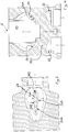
- the reference number 1 indicates a gear pump.
- Said pump 1 comprises a compartment 20 housing said gears which transfer energy to a fluid crossing the pump 1.
- the gears comprise two cogwheels that reciprocally mesh and are positioned in the housing compartment 20.
- One of the gears could possibly have external teeth and the other internal teeth.
- the two gears could be rolling bodies that interact with each other, but do not have an involute profile (for example, a lobe pump).
- the pump 1 also comprises a first conduit 21 which develops from the housing compartment 20.
- said first conduit 21 is a delivery conduit.
- the first conduit 21 is thus used for discharging the fluid under pressure from the compartment 20.
- the pump 1 comprises a first stiffening rib 31 that crosses the first conduit 21.
- the first stiffening rib 31 divides the flow of fluid into at least two parts. The two parts reconverge downstream of said first rib 31.
- the first rib 31 thus serves to stiffen the delivery conduit, minimising the tensions of the material and consequently the deformations without oversizing in thickness the walls of the first conduit 21. It is thus possible to minimise the outer dimensions of the pump 1.
- the first stiffening rib 31 comprises a fin 310 having an aerodynamic profile. This enables pressure drops to be minimised. An even more important advantage may be had in the case of a reversible pump, as better explained below.
- the pump 1 advantageously comprises a second conduit 22 which terminates in said housing compartment 20.
- the second conduit 22 is an aspirating conduit.
- the pump 1 also comprises a second stiffening rib 32 crossing said second conduit 22.
- the pump 1 is reversible. It can thus also function in a second operating mode in which the first conduit 21 becomes an aspirating conduit and the second conduit 22 becomes a delivery conduit.
- the presence of the rib 32 also in the second conduit 22 is thus important.
- the second conduit 22 can also become a delivery conduit and therefore be subject to considerable stresses due to the fluid under pressure.
- the second stiffening rib 32 comprises a fin 320 having an aerodynamic profile.
- this feature serves to minimise the pressure drops on the aspirating side in order to reduce the risk of cavitation (in the first operating mode the second rib 32 operates under aspiration and the aerodynamic profile helps for that purpose).
- first conduit 21 and the second conduit 22 comprise two ports 23, 24 which lie side by side on a same wall of the pump 1, turned outward. Internally of the pump the first and the second conduit 21, 22 extend side by side.
- the two ports 23, 24 of the first and the second conduit 21, 22 could be located on two distinct walls of the pump 1; in particular, they could be lateral.
- first conduit 21 and the first rib 31 are in a single monolithic body.
- the second conduit 22, the second rib 32 and at least a part of the housing compartment 20 are in a single monolithic body.
- the single monolithic body is advantageously made of cast iron.
- the single monolithic body also defines an external casing that delimits at least in part the pump 1 from the outside.
- the first conduit 21, the second conduit 22, the first and second rib 31, 32 and at least a part of the housing compartment 20 are symmetrical with respect to a median plane 4 interposed between the first and the second conduit 21, 22.
- the first rib 31 comprises:
- the first and the second surface 311, 312 comprise a portion 315 in which they are reciprocally divergent and a portion 316 in which they are reciprocally convergent.
- One of the two parts of the flow divided by said first rib 31 skims over the first surface 311 and the other over the second surface 312.
- the first conduit 21 comprises a first delimiting wall 25 that faces the first surface 311 and defines a concavity turned toward the first surface 311.
- the first conduit 21 comprises a second delimiting wall 26 of that faces the second surface 312 and defines a concavity turned toward the second surface 312.
- the first rib 31 connects to remaining parts of the monolithic body at a first and a second end 317, 318 thereof, which are reciprocally opposite.
- the first end 317 is closer to an outer surface of the pump than the second end 318.
- At least a transversal section that is intermediate with respect to the first and the second end 317, 318 has a smaller surface than a surface of the transversal section measured at the first and second end 317, 318.
- the intermediate section has a chord and/or average thickness that is/are smaller than those of the transversal section measured at the first and the second end 317, 318.
- the first rib 31 has a larger transversal section at the first end 317 than at the second end 318.
- the invention thus conceived enables multiple advantages to be obtained. First of all, it permits a reduction in the overall dimensions of the pump 1.
- the first rib 31 (positioned in the first conduit 21) enables the delivery side of the pump 1 to be stiffened without reinforcing the thickness of the conduits.
- the aerodynamic shape of the fin makes it possible to avoid significant pressure drops on the aspirating side (and the consequent risk of cavitation) in the event that the pump functions in a reversible mode and the first conduit 21 thus acts as an aspirating conduit.
- the invention thus conceived is susceptible of numerous modifications and variants, all falling within the scope of the inventive concept characterising it. Moreover, all of the details may be replaced with technically equivalent elements. In practice, all of the materials used, as well as the dimensions, may be of any type, according to need.
Landscapes
- Engineering & Computer Science (AREA)
- Mechanical Engineering (AREA)
- General Engineering & Computer Science (AREA)
- Rotary Pumps (AREA)
Claims (9)
- Pompe à engrenages comprenant :- un compartiment de logement (20) desdits engrenages qui transfèrent de l'énergie vers un fluide traversant la pompe (1) ;- une première conduite (21) se développant à partir du compartiment de logement (20), dans un premier mode de fonctionnement ladite première conduite (21) étant une conduite de refoulement ;caractérisée en ce qu'elle comprend- une première nervure de renforcement (31) traversant ladite première conduite (21) et étant destinée à diviser en au moins deux parties le flux de fluide transitant en correspondance de ladite première nervure (31) ;ladite première nervure (31) comprend :- une première et une seconde surface (311, 312) étant mutuellement opposées l'une à l'autre ;- un bord d'attaque (313) et un bord de sortie (314) de la première nervure (31) étant arrondis et qui relient réciproquement la première et la seconde surface (311, 312) .
- Pompe selon la revendication 1, caractérisée en ce que ladite première nervure de renforcement (31) comprend une ailette (310) ayant un profil aérodynamique.
- Pompe selon la revendication 1 ou 2, caractérisée en ce qu'elle comprend :- une seconde conduite (22) se terminant dans ledit compartiment de logement (20), dans le premier mode de fonctionnement ladite seconde conduite (22) étant une conduite d'aspiration ;- une seconde nervure de renforcement (32) traversant ladite seconde conduite (22) ;la pompe (1) étant réversible et pouvant fonctionner aussi dans un second mode de fonctionnement dans lequel ladite première conduite (21) devient une conduite d'aspiration et ladite seconde conduite (22) devient une conduite de refoulement.
- Pompe selon la revendication 3, caractérisée en ce que ladite seconde nervure de renforcement (32) comprend une ailette (320) ayant un profil aérodynamique.
- Pompe selon l'une quelconque des revendications précédentes, caractérisée en ce que ladite première conduite (21) et ladite première nervure (31) se présentent sous la forme d'un corps monolithique unique.
- Pompe selon la revendication 3 ou 4, caractérisée en ce que ladite première conduite (21), ladite seconde conduite (22), lesdites première et seconde nervures (31, 32) et au moins une partie du compartiment de logement (20) se présentent sous la forme d'un corps monolithique unique.
- Pompe selon la revendication 3 ou 4 ou 6, caractérisée en ce que ladite première conduite (21), ladite seconde conduite (22), lesdites première et seconde nervures (31, 32) et au moins une partie du compartiment de logement (20) sont symétriques par rapport à un plan médian (4) interposé entre la première et la seconde conduite (21, 22).
- Pompe selon l'une quelconque des revendications précédentes, caractérisée en ce que par rapport à un parcours allant du compartiment de logement (20) vers un extérieur de la pompe (1) le long de la première conduite (21), la première nervure
(31) comprend :- une partie (315) dans laquelle la première et la seconde surface (311, 312) sont divergentes réciproquement ; et- une partie (316) dans laquelle la première et la seconde surface (311, 312) sont convergentes réciproquement. - Pompe selon la revendication 5 ou 6, caractérisée en ce que ladite première nervure (31) relie les parties restantes du corps monolithique à ses première et seconde extrémités (317, 318), réciproquement opposées ;
au moins une section transversale, étant intermédiaire par rapport aux première et seconde extrémités (317, 318), comportant une surface plus petite qu'une surface de la section transversale mesurée entre la première et la seconde extrémité.
Applications Claiming Priority (1)
| Application Number | Priority Date | Filing Date | Title |
|---|---|---|---|
| ITUB20150848 | 2015-05-20 |
Publications (2)
| Publication Number | Publication Date |
|---|---|
| EP3096015A1 EP3096015A1 (fr) | 2016-11-23 |
| EP3096015B1 true EP3096015B1 (fr) | 2019-12-04 |
Family
ID=53901006
Family Applications (1)
| Application Number | Title | Priority Date | Filing Date |
|---|---|---|---|
| EP16169754.5A Active EP3096015B1 (fr) | 2015-05-20 | 2016-05-16 | Pompe à engrenages |
Country Status (1)
| Country | Link |
|---|---|
| EP (1) | EP3096015B1 (fr) |
Family Cites Families (4)
| Publication number | Priority date | Publication date | Assignee | Title |
|---|---|---|---|---|
| US6976833B2 (en) * | 2003-11-17 | 2005-12-20 | Carrier Corporation | Compressor discharge chamber with baffle plate |
| US20100135839A1 (en) * | 2006-12-26 | 2010-06-03 | Fraser Bruce A | Screw compressor with integral bearing cover and discharge plenum divider |
| MX2010010967A (es) * | 2008-04-09 | 2010-11-05 | Nestec Sa | Bombas de engranaje y metodos para usar las bombas de engranaje. |
| GB2507029B (en) * | 2012-07-11 | 2019-04-17 | Quantex Patents Ltd | Pump fittings and methods for their manufacture |
-
2016
- 2016-05-16 EP EP16169754.5A patent/EP3096015B1/fr active Active
Non-Patent Citations (1)
| Title |
|---|
| None * |
Also Published As
| Publication number | Publication date |
|---|---|
| EP3096015A1 (fr) | 2016-11-23 |
Similar Documents
| Publication | Publication Date | Title |
|---|---|---|
| US9897086B2 (en) | Vane pump | |
| US20120121449A1 (en) | Check valve | |
| JP5043930B2 (ja) | 最外伝熱板の外側に設けられた補強板を含むプレート熱交換器 | |
| MX2009013028A (es) | Bomba e impulsor de bomba. | |
| KR20070106654A (ko) | 특히 2 실린더 물질 펌프를 위한 유압구동수단 | |
| CA2557493A1 (fr) | Pale ou aube pour une turbomachine | |
| WO2011064281A3 (fr) | Pompe à palettes | |
| RU2016150979A (ru) | Отводящее колено | |
| KR100838424B1 (ko) | 배플판을 갖는 압축기 배출 챔버 | |
| EP3096015B1 (fr) | Pompe à engrenages | |
| EP3019750B1 (fr) | Compresseur à vis ayant un orifice d'économiseur | |
| US9046099B2 (en) | Delivery unit | |
| JP5826295B2 (ja) | 流体を制御する又は調量する弁装置 | |
| US11333136B2 (en) | Fluid pump with cam geometry to reduce pulsations | |
| JPWO2021192238A5 (fr) | ||
| WO2009103930A3 (fr) | Compresseur frigorifique à spirales | |
| CN106168211B (zh) | 齿轮泵 | |
| EP3245405B2 (fr) | Élément de pompe à vide à injection d'huile | |
| US10174759B2 (en) | Dual pump system | |
| WO2011038807A8 (fr) | Pompe d'aspiration à membrane à plusieurs étages | |
| EP2831487B1 (fr) | Pompe à huile, capot de moteur et moteur comprenant ce dernier | |
| KR20140050006A (ko) | 유공압 장치 및 키트 | |
| JP2009236074A (ja) | 二連歯車ポンプ | |
| EP4095381A1 (fr) | Pompe à trajet de fluide complexe | |
| WO2008029477A1 (fr) | Pompe à engrenages |
Legal Events
| Date | Code | Title | Description |
|---|---|---|---|
| PUAI | Public reference made under article 153(3) epc to a published international application that has entered the european phase |
Free format text: ORIGINAL CODE: 0009012 |
|
| AK | Designated contracting states |
Kind code of ref document: A1 Designated state(s): AL AT BE BG CH CY CZ DE DK EE ES FI FR GB GR HR HU IE IS IT LI LT LU LV MC MK MT NL NO PL PT RO RS SE SI SK SM TR |
|
| AX | Request for extension of the european patent |
Extension state: BA ME |
|
| STAA | Information on the status of an ep patent application or granted ep patent |
Free format text: STATUS: REQUEST FOR EXAMINATION WAS MADE |
|
| 17P | Request for examination filed |
Effective date: 20170421 |
|
| RBV | Designated contracting states (corrected) |
Designated state(s): AL AT BE BG CH CY CZ DE DK EE ES FI FR GB GR HR HU IE IS IT LI LT LU LV MC MK MT NL NO PL PT RO RS SE SI SK SM TR |
|
| STAA | Information on the status of an ep patent application or granted ep patent |
Free format text: STATUS: EXAMINATION IS IN PROGRESS |
|
| 17Q | First examination report despatched |
Effective date: 20181126 |
|
| GRAP | Despatch of communication of intention to grant a patent |
Free format text: ORIGINAL CODE: EPIDOSNIGR1 |
|
| STAA | Information on the status of an ep patent application or granted ep patent |
Free format text: STATUS: GRANT OF PATENT IS INTENDED |
|
| INTG | Intention to grant announced |
Effective date: 20190911 |
|
| GRAS | Grant fee paid |
Free format text: ORIGINAL CODE: EPIDOSNIGR3 |
|
| GRAA | (expected) grant |
Free format text: ORIGINAL CODE: 0009210 |
|
| STAA | Information on the status of an ep patent application or granted ep patent |
Free format text: STATUS: THE PATENT HAS BEEN GRANTED |
|
| AK | Designated contracting states |
Kind code of ref document: B1 Designated state(s): AL AT BE BG CH CY CZ DE DK EE ES FI FR GB GR HR HU IE IS IT LI LT LU LV MC MK MT NL NO PL PT RO RS SE SI SK SM TR |
|
| REG | Reference to a national code |
Ref country code: GB Ref legal event code: FG4D |
|
| REG | Reference to a national code |
Ref country code: CH Ref legal event code: EP |
|
| REG | Reference to a national code |
Ref country code: AT Ref legal event code: REF Ref document number: 1209740 Country of ref document: AT Kind code of ref document: T Effective date: 20191215 |
|
| REG | Reference to a national code |
Ref country code: DE Ref legal event code: R096 Ref document number: 602016025370 Country of ref document: DE |
|
| REG | Reference to a national code |
Ref country code: IE Ref legal event code: FG4D |
|
| REG | Reference to a national code |
Ref country code: NL Ref legal event code: MP Effective date: 20191204 |
|
| REG | Reference to a national code |
Ref country code: LT Ref legal event code: MG4D |
|
| PG25 | Lapsed in a contracting state [announced via postgrant information from national office to epo] |
Ref country code: SE Free format text: LAPSE BECAUSE OF FAILURE TO SUBMIT A TRANSLATION OF THE DESCRIPTION OR TO PAY THE FEE WITHIN THE PRESCRIBED TIME-LIMIT Effective date: 20191204 Ref country code: LV Free format text: LAPSE BECAUSE OF FAILURE TO SUBMIT A TRANSLATION OF THE DESCRIPTION OR TO PAY THE FEE WITHIN THE PRESCRIBED TIME-LIMIT Effective date: 20191204 Ref country code: GR Free format text: LAPSE BECAUSE OF FAILURE TO SUBMIT A TRANSLATION OF THE DESCRIPTION OR TO PAY THE FEE WITHIN THE PRESCRIBED TIME-LIMIT Effective date: 20200305 Ref country code: NO Free format text: LAPSE BECAUSE OF FAILURE TO SUBMIT A TRANSLATION OF THE DESCRIPTION OR TO PAY THE FEE WITHIN THE PRESCRIBED TIME-LIMIT Effective date: 20200304 Ref country code: BG Free format text: LAPSE BECAUSE OF FAILURE TO SUBMIT A TRANSLATION OF THE DESCRIPTION OR TO PAY THE FEE WITHIN THE PRESCRIBED TIME-LIMIT Effective date: 20200304 Ref country code: FI Free format text: LAPSE BECAUSE OF FAILURE TO SUBMIT A TRANSLATION OF THE DESCRIPTION OR TO PAY THE FEE WITHIN THE PRESCRIBED TIME-LIMIT Effective date: 20191204 Ref country code: LT Free format text: LAPSE BECAUSE OF FAILURE TO SUBMIT A TRANSLATION OF THE DESCRIPTION OR TO PAY THE FEE WITHIN THE PRESCRIBED TIME-LIMIT Effective date: 20191204 |
|
| PG25 | Lapsed in a contracting state [announced via postgrant information from national office to epo] |
Ref country code: HR Free format text: LAPSE BECAUSE OF FAILURE TO SUBMIT A TRANSLATION OF THE DESCRIPTION OR TO PAY THE FEE WITHIN THE PRESCRIBED TIME-LIMIT Effective date: 20191204 Ref country code: RS Free format text: LAPSE BECAUSE OF FAILURE TO SUBMIT A TRANSLATION OF THE DESCRIPTION OR TO PAY THE FEE WITHIN THE PRESCRIBED TIME-LIMIT Effective date: 20191204 |
|
| PG25 | Lapsed in a contracting state [announced via postgrant information from national office to epo] |
Ref country code: AL Free format text: LAPSE BECAUSE OF FAILURE TO SUBMIT A TRANSLATION OF THE DESCRIPTION OR TO PAY THE FEE WITHIN THE PRESCRIBED TIME-LIMIT Effective date: 20191204 |
|
| PG25 | Lapsed in a contracting state [announced via postgrant information from national office to epo] |
Ref country code: CZ Free format text: LAPSE BECAUSE OF FAILURE TO SUBMIT A TRANSLATION OF THE DESCRIPTION OR TO PAY THE FEE WITHIN THE PRESCRIBED TIME-LIMIT Effective date: 20191204 Ref country code: PT Free format text: LAPSE BECAUSE OF FAILURE TO SUBMIT A TRANSLATION OF THE DESCRIPTION OR TO PAY THE FEE WITHIN THE PRESCRIBED TIME-LIMIT Effective date: 20200429 Ref country code: ES Free format text: LAPSE BECAUSE OF FAILURE TO SUBMIT A TRANSLATION OF THE DESCRIPTION OR TO PAY THE FEE WITHIN THE PRESCRIBED TIME-LIMIT Effective date: 20191204 Ref country code: RO Free format text: LAPSE BECAUSE OF FAILURE TO SUBMIT A TRANSLATION OF THE DESCRIPTION OR TO PAY THE FEE WITHIN THE PRESCRIBED TIME-LIMIT Effective date: 20191204 Ref country code: EE Free format text: LAPSE BECAUSE OF FAILURE TO SUBMIT A TRANSLATION OF THE DESCRIPTION OR TO PAY THE FEE WITHIN THE PRESCRIBED TIME-LIMIT Effective date: 20191204 Ref country code: NL Free format text: LAPSE BECAUSE OF FAILURE TO SUBMIT A TRANSLATION OF THE DESCRIPTION OR TO PAY THE FEE WITHIN THE PRESCRIBED TIME-LIMIT Effective date: 20191204 |
|
| PG25 | Lapsed in a contracting state [announced via postgrant information from national office to epo] |
Ref country code: SM Free format text: LAPSE BECAUSE OF FAILURE TO SUBMIT A TRANSLATION OF THE DESCRIPTION OR TO PAY THE FEE WITHIN THE PRESCRIBED TIME-LIMIT Effective date: 20191204 Ref country code: IS Free format text: LAPSE BECAUSE OF FAILURE TO SUBMIT A TRANSLATION OF THE DESCRIPTION OR TO PAY THE FEE WITHIN THE PRESCRIBED TIME-LIMIT Effective date: 20200404 Ref country code: SK Free format text: LAPSE BECAUSE OF FAILURE TO SUBMIT A TRANSLATION OF THE DESCRIPTION OR TO PAY THE FEE WITHIN THE PRESCRIBED TIME-LIMIT Effective date: 20191204 |
|
| REG | Reference to a national code |
Ref country code: DE Ref legal event code: R097 Ref document number: 602016025370 Country of ref document: DE |
|
| REG | Reference to a national code |
Ref country code: AT Ref legal event code: MK05 Ref document number: 1209740 Country of ref document: AT Kind code of ref document: T Effective date: 20191204 |
|
| PLBE | No opposition filed within time limit |
Free format text: ORIGINAL CODE: 0009261 |
|
| STAA | Information on the status of an ep patent application or granted ep patent |
Free format text: STATUS: NO OPPOSITION FILED WITHIN TIME LIMIT |
|
| PG25 | Lapsed in a contracting state [announced via postgrant information from national office to epo] |
Ref country code: DK Free format text: LAPSE BECAUSE OF FAILURE TO SUBMIT A TRANSLATION OF THE DESCRIPTION OR TO PAY THE FEE WITHIN THE PRESCRIBED TIME-LIMIT Effective date: 20191204 |
|
| 26N | No opposition filed |
Effective date: 20200907 |
|
| PG25 | Lapsed in a contracting state [announced via postgrant information from national office to epo] |
Ref country code: AT Free format text: LAPSE BECAUSE OF FAILURE TO SUBMIT A TRANSLATION OF THE DESCRIPTION OR TO PAY THE FEE WITHIN THE PRESCRIBED TIME-LIMIT Effective date: 20191204 Ref country code: SI Free format text: LAPSE BECAUSE OF FAILURE TO SUBMIT A TRANSLATION OF THE DESCRIPTION OR TO PAY THE FEE WITHIN THE PRESCRIBED TIME-LIMIT Effective date: 20191204 Ref country code: PL Free format text: LAPSE BECAUSE OF FAILURE TO SUBMIT A TRANSLATION OF THE DESCRIPTION OR TO PAY THE FEE WITHIN THE PRESCRIBED TIME-LIMIT Effective date: 20191204 |
|
| PG25 | Lapsed in a contracting state [announced via postgrant information from national office to epo] |
Ref country code: CH Free format text: LAPSE BECAUSE OF NON-PAYMENT OF DUE FEES Effective date: 20200531 Ref country code: LI Free format text: LAPSE BECAUSE OF NON-PAYMENT OF DUE FEES Effective date: 20200531 Ref country code: MC Free format text: LAPSE BECAUSE OF FAILURE TO SUBMIT A TRANSLATION OF THE DESCRIPTION OR TO PAY THE FEE WITHIN THE PRESCRIBED TIME-LIMIT Effective date: 20191204 |
|
| REG | Reference to a national code |
Ref country code: BE Ref legal event code: MM Effective date: 20200531 |
|
| GBPC | Gb: european patent ceased through non-payment of renewal fee |
Effective date: 20200516 |
|
| PG25 | Lapsed in a contracting state [announced via postgrant information from national office to epo] |
Ref country code: LU Free format text: LAPSE BECAUSE OF NON-PAYMENT OF DUE FEES Effective date: 20200516 |
|
| PG25 | Lapsed in a contracting state [announced via postgrant information from national office to epo] |
Ref country code: IE Free format text: LAPSE BECAUSE OF NON-PAYMENT OF DUE FEES Effective date: 20200516 Ref country code: GB Free format text: LAPSE BECAUSE OF NON-PAYMENT OF DUE FEES Effective date: 20200516 |
|
| PG25 | Lapsed in a contracting state [announced via postgrant information from national office to epo] |
Ref country code: BE Free format text: LAPSE BECAUSE OF NON-PAYMENT OF DUE FEES Effective date: 20200531 |
|
| PG25 | Lapsed in a contracting state [announced via postgrant information from national office to epo] |
Ref country code: MT Free format text: LAPSE BECAUSE OF FAILURE TO SUBMIT A TRANSLATION OF THE DESCRIPTION OR TO PAY THE FEE WITHIN THE PRESCRIBED TIME-LIMIT Effective date: 20191204 Ref country code: CY Free format text: LAPSE BECAUSE OF FAILURE TO SUBMIT A TRANSLATION OF THE DESCRIPTION OR TO PAY THE FEE WITHIN THE PRESCRIBED TIME-LIMIT Effective date: 20191204 |
|
| PG25 | Lapsed in a contracting state [announced via postgrant information from national office to epo] |
Ref country code: MK Free format text: LAPSE BECAUSE OF FAILURE TO SUBMIT A TRANSLATION OF THE DESCRIPTION OR TO PAY THE FEE WITHIN THE PRESCRIBED TIME-LIMIT Effective date: 20191204 |
|
| P01 | Opt-out of the competence of the unified patent court (upc) registered |
Effective date: 20230517 |
|
| PGFP | Annual fee paid to national office [announced via postgrant information from national office to epo] |
Ref country code: DE Payment date: 20250528 Year of fee payment: 10 |
|
| PGFP | Annual fee paid to national office [announced via postgrant information from national office to epo] |
Ref country code: IT Payment date: 20250528 Year of fee payment: 10 |
|
| PGFP | Annual fee paid to national office [announced via postgrant information from national office to epo] |
Ref country code: FR Payment date: 20250526 Year of fee payment: 10 |
|
| PGFP | Annual fee paid to national office [announced via postgrant information from national office to epo] |
Ref country code: TR Payment date: 20250428 Year of fee payment: 10 |