EP3096021A1 - Télé-diagnostic d'appareils sous vide - Google Patents
Télé-diagnostic d'appareils sous vide Download PDFInfo
- Publication number
- EP3096021A1 EP3096021A1 EP15168485.9A EP15168485A EP3096021A1 EP 3096021 A1 EP3096021 A1 EP 3096021A1 EP 15168485 A EP15168485 A EP 15168485A EP 3096021 A1 EP3096021 A1 EP 3096021A1
- Authority
- EP
- European Patent Office
- Prior art keywords
- diagnostic data
- vacuum device
- vacuum
- data
- entirety
- Prior art date
- Legal status (The legal status is an assumption and is not a legal conclusion. Google has not performed a legal analysis and makes no representation as to the accuracy of the status listed.)
- Granted
Links
Images

Classifications
-
- F—MECHANICAL ENGINEERING; LIGHTING; HEATING; WEAPONS; BLASTING
- F04—POSITIVE - DISPLACEMENT MACHINES FOR LIQUIDS; PUMPS FOR LIQUIDS OR ELASTIC FLUIDS
- F04D—NON-POSITIVE-DISPLACEMENT PUMPS
- F04D19/00—Axial-flow pumps
- F04D19/02—Multi-stage pumps
- F04D19/04—Multi-stage pumps specially adapted to the production of a high vacuum, e.g. molecular pumps
-
- F—MECHANICAL ENGINEERING; LIGHTING; HEATING; WEAPONS; BLASTING
- F04—POSITIVE - DISPLACEMENT MACHINES FOR LIQUIDS; PUMPS FOR LIQUIDS OR ELASTIC FLUIDS
- F04C—ROTARY-PISTON, OR OSCILLATING-PISTON, POSITIVE-DISPLACEMENT MACHINES FOR LIQUIDS; ROTARY-PISTON, OR OSCILLATING-PISTON, POSITIVE-DISPLACEMENT PUMPS
- F04C25/00—Adaptations of pumps for special use of pumps for elastic fluids
- F04C25/02—Adaptations of pumps for special use of pumps for elastic fluids for producing high vacuum
-
- F—MECHANICAL ENGINEERING; LIGHTING; HEATING; WEAPONS; BLASTING
- F04—POSITIVE - DISPLACEMENT MACHINES FOR LIQUIDS; PUMPS FOR LIQUIDS OR ELASTIC FLUIDS
- F04D—NON-POSITIVE-DISPLACEMENT PUMPS
- F04D27/00—Control, e.g. regulation, of pumps, pumping installations or pumping systems specially adapted for elastic fluids
- F04D27/001—Testing thereof; Determination or simulation of flow characteristics; Stall or surge detection, e.g. condition monitoring
-
- F—MECHANICAL ENGINEERING; LIGHTING; HEATING; WEAPONS; BLASTING
- F04—POSITIVE - DISPLACEMENT MACHINES FOR LIQUIDS; PUMPS FOR LIQUIDS OR ELASTIC FLUIDS
- F04C—ROTARY-PISTON, OR OSCILLATING-PISTON, POSITIVE-DISPLACEMENT MACHINES FOR LIQUIDS; ROTARY-PISTON, OR OSCILLATING-PISTON, POSITIVE-DISPLACEMENT PUMPS
- F04C2270/00—Control; Monitoring or safety arrangements
- F04C2270/80—Diagnostics
-
- F—MECHANICAL ENGINEERING; LIGHTING; HEATING; WEAPONS; BLASTING
- F04—POSITIVE - DISPLACEMENT MACHINES FOR LIQUIDS; PUMPS FOR LIQUIDS OR ELASTIC FLUIDS
- F04C—ROTARY-PISTON, OR OSCILLATING-PISTON, POSITIVE-DISPLACEMENT MACHINES FOR LIQUIDS; ROTARY-PISTON, OR OSCILLATING-PISTON, POSITIVE-DISPLACEMENT PUMPS
- F04C2270/00—Control; Monitoring or safety arrangements
- F04C2270/90—Remote control, e.g. wireless, via LAN, by radio, or by a wired connection from a central computer
-
- F—MECHANICAL ENGINEERING; LIGHTING; HEATING; WEAPONS; BLASTING
- F05—INDEXING SCHEMES RELATING TO ENGINES OR PUMPS IN VARIOUS SUBCLASSES OF CLASSES F01-F04
- F05D—INDEXING SCHEME FOR ASPECTS RELATING TO NON-POSITIVE-DISPLACEMENT MACHINES OR ENGINES, GAS-TURBINES OR JET-PROPULSION PLANTS
- F05D2260/00—Function
- F05D2260/80—Diagnostics
Definitions
- the invention relates to a vacuum device and a remote diagnosis method for vacuum devices.
- Vacuum devices such as, in particular, vacuum pumps or the like are used in various fields of technology in order to create a vacuum necessary for a respective process.
- Vacuum devices typically have a user-friendly, relatively simple user interface and / or user interface provided only for limited data exchange with the user.
- a user interface or user interface mostly only serves to retrieve the data necessary for the current requirement or for normal operation on site, such as data for the states on / off, the rotational speed, an error status or the like.
- the invention has for its object to provide a vacuum device and a remote diagnosis method with which the aforementioned problems are eliminated. It should be ensured in the simplest possible way that the diagnostic data required for a remote diagnosis can be provided completely and unadulterated, even in environments where a high level of data security is required.
- the vacuum device comprises a device for generating a total of diagnostic data of the vacuum device suitable at a remote analysis location, a retrieval device, by means of which a provision of the entirety of diagnostic data can be initiated, and a provision device, which is configured to collect the entirety of diagnostic data for To provide transmission as a whole to the remote analysis site as a whole.
- the vacuum device now has the ability to provide all the diagnostic data necessary for a remote analysis at once, while also ensuring that the diagnostic data at the remote analysis site are available in an unadulterated manner.
- a person on the ground as a "procurer” of the data and / or as a "transmission" of the data to the remote analysts is no longer necessary.
- the provision of the diagnostic data can still be caused by a local person.
- Special knowledge, special equipment or excessive care are not required.
- a reliable comprehensive error analysis is possible by the invention at the remote location analysis.
- the entirety of the diagnostic data should be divided into several individual units (eg optically coded display on multiple images to be transmitted or on output of multiple data streams), this still is provision and transmission of all diagnostic data suitable for the analysis "all at once" or “at one go” or “at one go” within the meaning of the invention.
- provision and transmission of the diagnostic data occur even with such a division into several individual units not awkward and error prone “step by step” or in the form of a "man-machine” dialogue as in the prior art.
- the diagnostic data is different from operating data of the vacuum device intended for normal operation in the field.
- the diagnostic data may have a reduced or extended content-related and / or data-quantity-related scope compared to the normal operating data with regard to the respective diagnostic purpose. In principle, this is not mandatory.
- the diagnostic data may also be identical to the normal operating data.
- the provision of the entirety of diagnostic data can be on, in particular only once, request or automatically initiated.
- the retrieval device initiates the provision only if a corresponding command is issued, for example, by a user by pressing a button or by another device by a control parameter.
- the provision can also be triggered automatically, for example, each time the vacuum device is switched on.
- the diagnostic data are displayed on a display until a predetermined period has expired, the user presses a specific or any key, or in any manner defined manner a normal operation of the Vacuum device begins.
- An automatic provision of the diagnostic data can also be triggered by an occurring after switching on or off or during normal operation of the vacuum device error or a predetermined error state, ie the retrieval device initiated in this variant, the provision of diagnostic data automatically when due to an error Diagnosis could be required.
- embodiments are possible in which the initiation of the provision of the diagnostic data, that is to say the initial act of the diagnostic start, is switched on or off of the vacuum device or its mains supply or, as it were, on the correct moment (eg when an error occurs) ) is reduced. For example, triggering a command or setting a parameter is no longer required.
- such embodiments are possible in which no interaction with the vacuum device at all is necessary.
- the invention can then also be used for such vacuum devices which have no keys or other input means or which are not accessible due to their installation situation.
- a vacuum device in a contaminated or hermetically protected - and thus in a not easily accessible - area arranged and still allow a transfer of diagnostic data easily, for example, simply by photographing a display of the diagnostic data display of the vacuum device through a glass pane.
- the diagnostic data - at least for a predetermined or predeterminable period of time - are provided permanently or alternately.
- the diagnostic data may thus be e.g. be displayed permanently until a user stops the display by pressing a key or a control command.
- the diagnostic data may be displayed in alternation with the normal operational data, and such an alternate indication may be terminated once the transmission of the diagnostic data is completed.
- the vacuum device "jumps" from a normal display mode to a diagnostic data display mode upon the occurrence of an error for a predetermined period of time to the user to be able to record the diagnostic data "at the right time” for transmission without further interaction with the vacuum device.
- the entirety of the diagnostic data can be provided in encoded form.
- the entirety of the diagnostic data can be provided in compressed form.
- the entirety of the diagnostic data can be provided in such a coded form that the entirety of the diagnostic data can be transmitted to the remote analysis location independently of local functionalities provided for normal operation on site, in particular independently of local character sets.
- the vacuum device is already connected to another device of the user via an electronic user interface or user interface, so that the user has the option of obtaining an extended data stream, for example by means of a defined manual read-out command. not only gives a short response or acknowledgment to a command, but provides a multiple-sized data stream (e.g., "stream", "dump") and contains the entirety of the diagnostic data.
- a multiple-sized data stream e.g., "stream", "dump”
- the entirety of the diagnostic data can thus be output in the form of a data stream.
- the data stream can be at the remote analysis location optionally after a corresponding decoding and / or decompression are processed.
- a base64 encoding carrying a CRC checksum and / or the grouping of data by means of headers or einklammernden head and tail characters and / or features conceivable.
- Base64 describes a method of encoding 8-bit binary data in a string consisting of readable codepage-independent ASCII characters only.
- a checksum (CR-24) can still be appended, whereby this slightly modified method bears the name Radix-64.
- other codings are conceivable.
- the entirety of the diagnostic data can be provided in optically coded form.
- the provisioning device comprises a display on which the diagnostic data can be displayed.
- optically coded diagnostic data can be photographed or filmed for transmission to the remote analysis location of the display.
- the entire set of diagnostic data can be collected with typically user-provided devices and transmitted via a communication link to the remote analysis location.
- the display provided for reproducing the diagnostic data can be integrated in the vacuum device or placed remotely from the vacuum device and connected to the vacuum device via a local data connection.
- the display provided for displaying the diagnostic data can also be associated, for example, with a plurality of vacuum devices.
- Switching means may be provided, via which the display is optionally connectable to the various vacuum devices.
- the respective connection can in particular be wired in each case and / or be produced by radio.
- the entirety of the diagnostic data can be displayed on the display in a single image or else consecutively in several images.
- the parts of the totality of the diagnostic data corresponding to the individual images each represent a consistent subset of the totality of diagnostic data provided for transmission to the remote analysis location.
- each part of the entirety of the diagnostic data is coded and / or encrypted and / or compressed.
- the whole set of diagnostic data can thus be stored in several successive steps in the form of data parts, e.g. Data sub-streams or images are transmitted over the relevant communication link to the remote analysis location.
- the entirety of the diagnostic data can be divided into more or fewer images, for example, photographed manually or automatically filmed one after the other from the display.
- Such a display can be triggered, for example, by a corresponding control parameter within a user interface or user interface, whereupon the display changes accordingly for the period of the presentation of the diagnostic data or a data subset and deviates from the normal function the corresponding diagnostic data for reading and / or mapping and / or or outputting.
- the amount of data provided per diagnostic step or per individual unit of diagnostic data is e.g. by the number of representable information units, e.g. Pixels, grayscale, colors and / or the like limited.
- a high-contrast dark-light bit pattern can be used, which can be safely coded by means of known algorithms.
- Examples include the DataMatrix code and the PDF417 code, each of which is an opto-electronically readable 2D code consisting of different widths or points and intervening gaps with as high a contrast as possible.
- the data are not only provided in one direction or one-dimensional, but in the form of an area over two dimensions.
- the data subsets to be transmitted via the communication connection to the remote analysis location each represent a consistent subset of the total totality of diagnostic data to be transmitted.
- the data received at the remote analysis location possible.
- an analysis unit may be provided with programming having corresponding image recognition logic.
- image recognition logic By means of a suitable image recognition system, display errors and distortions caused by the user can be compensated for and coded data at least substantially automatically extracted.
- an optical coding for example in the form of a two-dimensional line or dot code provides for a maximum degree of system security and data consistency, since no direct data connection to the vacuum device is required for transmitting the data and no return channel is available, beyond the otherwise malicious attack could take place.
- the integrity of a respective vacuum device is maintained to a much greater extent than in the hitherto known vacuum devices, e.g. via a cable or radio-bound coupling with, for example, a data carrier, such as e.g. a USB stick, an analysis system such as a handheld device or with any user device such. a tablet, mobile phone or PC, must be connected, as per se be pre-compromised and thus pose a threat to the vacuum device.
- a data carrier such as e.g. a USB stick
- an analysis system such as a handheld device or with any user device such. a tablet, mobile phone or PC
- the invention can also be used for very data- and security-sensitive users who are forced to operate systems certified safely and without external influences.
- the invention also relates to a method for the remote diagnosis of a vacuum device, in particular a vacuum pump.
- the vacuum apparatus comprises means for generating an aggregate of diagnostic data of the vacuum apparatus suitable for analysis to be performed at a remote analysis site, polling means for initiating provision of the set of diagnostic data, and provisioning means adapted to collect the set of diagnostic data to provide for transmission as a whole to the remote analysis site as a whole.
- the method provides that the diagnostic data is retrieved from the vacuum device by initiating the provision of the diagnostic data by means of the retrieval device, whereupon the diagnostic data is provided and transmitted to the remote analysis site as a whole, analyzing the diagnostic data at the remote analysis site, and that a diagnosis concerning the vacuum device is made.
- the diagnostic data of operating data of the vacuum device intended for normal operation are different in terms of content and / or scope.
- the method may provide that the provision of the entirety of diagnostic data is initiated on demand or automatically.
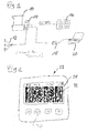
- Fig. 1 1 shows a schematic representation of a conventional vacuum device 10 in the form of a vacuum pump according to the prior art, which is connected to a power supply 12 and comprises an interface 14 to which a display 16 is connected and to which an on-site analysis or for a diagnosis of the vacuum device 10 on site via a service adapter 18, a service unit 20, here in the form of a portable computer, can be connected.
- a conventional vacuum device 10 of this type as explained in the introductory part - the diagnostic data displayed uncoded and must be queried individually and sequentially.
- the diagnostic data is provided on-site by a user e.g. read visually with the eyes, photographed or filmed and then usually have to be noted on a piece of paper or the like, so that they can then be discussed with the remote analyst sitting or transmitted to the analysts on the basis of the notes.
- the problem here is in practice that the remote analyst not all available for a reasonable error analysis diagnostic data are present, for example, if the user locally only procures the diagnostic data incomplete because he is overwhelmed with the situation, for. because he is not familiar with data or functionalities of the vacuum device that are not intended solely for normal operation on site or with the acquisition of the data required in the respective situation.
- FIG. 2 and 3 each show in a schematic partial representation of exemplary embodiments of a vacuum device 22 according to the invention, which may be, for example, a vacuum pump.
- the vacuum device 22 in each case comprises a device for generating a set of diagnostic data of the vacuum device 22 which are suitable for an analysis to be carried out at a remote analysis location and different from operating data of the vacuum device 22 provided for normal operation on site. Furthermore, the vacuum device 22 each comprises a retrieval device, by means of which a provision of the entirety of diagnostic data can be initiated on a single request, and a provision device, which is designed to provide the entirety of diagnostic data for transmission to the remote analysis site.
- the provision of the diagnostic data may e.g. be initiated by a user on site a provided on the vacuum device 22, here purely as an example integrated into a series of four control buttons integrated call button 34 or the vacuum device 22 via an interface with a polling signal applied, which is e.g. can be done via a local system or machine control, in which the vacuum device 22 is integrated.
- the mentioned button 34 or interface then represents the retrieval device or at least a part of the retrieval device of the vacuum device 22 according to the invention.
- a corresponding, to be actuated by a user call-off symbol on a then designed as a touch screen display of the vacuum device 22 may be provided.
- the diagnostic data provided by a respective vacuum device 22 according to the invention is via a communication link 24 to the remote Transferable analysis site, where they can be evaluated, for example by means of an analysis unit 26 (see. Fig. 3 ).
- the entirety of the diagnostic data is provided in each case in optically coded form, wherein the providing device in each case comprises a display 28 on which the diagnostic data are displayed in the form of a two-dimensional dot code.
- the display 28 may be e.g. integrated into the vacuum device 22 or arranged offset and be connected via a local data connection to the vacuum device 22. If the vacuum device 22 is, for example, a vacuum pump, then the display provided anyway in the vacuum pump can be used to display the diagnostic data.
- the optically coded diagnostic data displayed on the display 28 can be determined by means of an optoelectronic unit 30 (FIG. Fig. 3 ) are photographed or filmed by the display 28 and then transmitted via the communication link 24 to the remote analysis location or the analysis unit 26 provided there.
- an optoelectronic unit 30 a conventional camera such as a digital camera integrated in a mobile phone can be used.
- the image or the recorded film recorded with it can then be sent in a conventional manner, for example simply by electronic means via the Internet to the analysis location.
- the remote analyst receives by e-mail one or more images, each showing the display 28 of the vacuum device 22 and the coded diagnostic data displayed on the display 28.
- An encrypted transmission of the image or images is not necessary because each image already contains the diagnostic data in coded and thus in any secure encrypted form.
- the entirety of the diagnostic data in a single image 32 (see FIG. Fig. 2 ) or successively in a plurality of images 32 1 - 32 n (cf. Fig. 3 ) can be displayed on the display 28.
- the set of diagnostic data, as in Fig. 3 can be displayed on the display 28 successively in a plurality of images 32 1 - 32 n
- the parts of the totality of the diagnostic data corresponding to the individual images 32 1 - 32 n can each have a consistent subset of the entirety of the totality of Represent diagnostic data.
- the analysis unit 26 provided at the remote analysis location is provided with corresponding decoding and / or decompression means for decoding or decompressing the diagnostic data provided by the vacuum apparatus 22 and transmitted via the communication connection 24.
- switching means can be provided, via which the display 28 can be selectively connected to the respectively desired vacuum device 22.
- successive several images 32 1 - 32 n displayed on the display 28 and the individual images 32 1 - 32 n, for example, photographed manually or automatically can be filmed consecutively, so for example, by a corresponding control parameter of a user interface or user interface, a corresponding successive representation of the individual images 32 1 - 32 n triggered and then again the conversion to a normal playback function can be effected.
- the display 28 automatically falls back after a predeterminable time, after a single off and on of the mains voltage or any user inputs such as a keystroke or the like in the simple user or normal mode of operation.
- the communication connection 24 between the at least one vacuum device 22 and the remote analysis location or the analysis unit 26 may comprise, for example, a wireless connection, in particular a radio link, and / or an electrical line.
Landscapes
- Engineering & Computer Science (AREA)
- Mechanical Engineering (AREA)
- General Engineering & Computer Science (AREA)
- Compressors, Vaccum Pumps And Other Relevant Systems (AREA)
- Testing And Monitoring For Control Systems (AREA)
- Non-Positive Displacement Air Blowers (AREA)
- Control Of Positive-Displacement Pumps (AREA)
- Apparatus For Radiation Diagnosis (AREA)
Priority Applications (2)
| Application Number | Priority Date | Filing Date | Title |
|---|---|---|---|
| EP15168485.9A EP3096021B2 (fr) | 2015-05-20 | 2015-05-20 | Télé-diagnostic d'appareils sous vide |
| JP2016096837A JP2017002898A (ja) | 2015-05-20 | 2016-05-13 | 真空装置の遠隔診断 |
Applications Claiming Priority (1)
| Application Number | Priority Date | Filing Date | Title |
|---|---|---|---|
| EP15168485.9A EP3096021B2 (fr) | 2015-05-20 | 2015-05-20 | Télé-diagnostic d'appareils sous vide |
Publications (3)
| Publication Number | Publication Date |
|---|---|
| EP3096021A1 true EP3096021A1 (fr) | 2016-11-23 |
| EP3096021B1 EP3096021B1 (fr) | 2022-07-20 |
| EP3096021B2 EP3096021B2 (fr) | 2025-08-06 |
Family
ID=53188947
Family Applications (1)
| Application Number | Title | Priority Date | Filing Date |
|---|---|---|---|
| EP15168485.9A Active EP3096021B2 (fr) | 2015-05-20 | 2015-05-20 | Télé-diagnostic d'appareils sous vide |
Country Status (2)
| Country | Link |
|---|---|
| EP (1) | EP3096021B2 (fr) |
| JP (1) | JP2017002898A (fr) |
Cited By (4)
| Publication number | Priority date | Publication date | Assignee | Title |
|---|---|---|---|---|
| EP3396172A1 (fr) * | 2017-04-27 | 2018-10-31 | ebm-papst Mulfingen GmbH & Co. KG | Dispositif de lecture et d'affichage des paramètres de configuration à partir d'une unité de stockage de données d'un ventilateur |
| EP3427906A1 (fr) * | 2017-07-14 | 2019-01-16 | Vorwerk & Co. Interholding GmbH | Procédé de fonctionnement d'un robot en mouvement automatique |
| EP3647600A1 (fr) * | 2019-10-08 | 2020-05-06 | Pfeiffer Vacuum Gmbh | Identification d'un périphérique connecté électriquement |
| EP4586231A3 (fr) * | 2025-04-29 | 2025-11-05 | Pfeiffer Vacuum Technology AG | Procédé d'aide au fonctionnement d'un composant sous vide et système d'aide |
Families Citing this family (2)
| Publication number | Priority date | Publication date | Assignee | Title |
|---|---|---|---|---|
| GB2584431B (en) * | 2019-05-30 | 2021-10-13 | Aspen Pumps Ltd | Vacuum pump for use during maintenance or commissioning of an HVAC-R system, adapter for a vacuum pump, and a method of performing a vacuum test on an HVAC-R |
| EP3620660B1 (fr) * | 2019-08-06 | 2021-07-28 | Pfeiffer Vacuum Gmbh | Appareil à vide |
Citations (3)
| Publication number | Priority date | Publication date | Assignee | Title |
|---|---|---|---|---|
| US6022195A (en) * | 1988-09-13 | 2000-02-08 | Helix Technology Corporation | Electronically controlled vacuum pump with control module |
| EP1936198A2 (fr) * | 2006-12-13 | 2008-06-25 | Pfeiffer Vacuum Gmbh | Pompe à vide |
| DE202014005481U1 (de) * | 2014-07-04 | 2014-07-18 | Oerlikon Leybold Vacuum Gmbh | Vakuumpumpvorrichtung mit mindestens einem Pumpenmodul |
Family Cites Families (25)
| Publication number | Priority date | Publication date | Assignee | Title |
|---|---|---|---|---|
| JP3300770B2 (ja) | 1993-02-19 | 2002-07-08 | 株式会社日立製作所 | 可変容量形圧縮機 |
| US5713724A (en) | 1994-11-23 | 1998-02-03 | Coltec Industries Inc. | System and methods for controlling rotary screw compressors |
| US6175934B1 (en) | 1997-12-15 | 2001-01-16 | General Electric Company | Method and apparatus for enhanced service quality through remote diagnostics |
| US6272400B1 (en) | 1998-07-13 | 2001-08-07 | Helix Technology Corporation | Vacuum network controller |
| JP2000283056A (ja) * | 1999-03-26 | 2000-10-10 | Hitachi Ltd | 真空ポンプ異常監視システム |
| JP3179441B2 (ja) | 1999-03-30 | 2001-06-25 | セイコー精機株式会社 | 通信異常検出及び/又は対処装置及び真空ポンプ遠隔監視制御装置 |
| US20030046377A1 (en) | 2000-12-27 | 2003-03-06 | Wolfgang Daum | Method and apparatus for appliance service diagnostics |
| JP2003045431A (ja) | 2001-07-31 | 2003-02-14 | Toshiba Battery Co Ltd | 非水電解液電池 |
| DE10156927B4 (de) | 2001-11-21 | 2006-06-08 | Netzsch-Mohnopumpen Gmbh | Pumpencontroller mit Teileidentifikation |
| JP2003166477A (ja) | 2001-11-29 | 2003-06-13 | Furukawa Co Ltd | ポンプの性能診断キット及び性能診断キット取付用ポンプ |
| US20030114942A1 (en) | 2001-12-17 | 2003-06-19 | Varone John J. | Remote display module |
| JP3637331B2 (ja) * | 2002-05-28 | 2005-04-13 | 三菱重工業株式会社 | 遠隔からの監視を可能にするプラント監視装置 |
| JP4119295B2 (ja) | 2003-04-07 | 2008-07-16 | 東京エレクトロン株式会社 | 保守・診断データ蓄積サーバ、保守・診断データの蓄積・取得システム、保守・診断データの蓄積・提供システム |
| GB2424928A (en) | 2005-04-05 | 2006-10-11 | Boc Group Plc | Vacuum pumping control arrangement |
| KR20100129491A (ko) | 2009-06-01 | 2010-12-09 | (주)한국유체 | 스크류 압축기용 디지털 제어장치 |
| CN103415853B (zh) * | 2011-03-08 | 2018-04-17 | 甘布罗伦迪亚股份公司 | 收集统计和/或维护信息的方法和系统及交换数据的方法 |
| JP6040399B2 (ja) | 2011-10-17 | 2016-12-07 | 兵神装備株式会社 | 一軸偏心ねじポンプの遠隔モニタリングシステム |
| JP2015037762A (ja) * | 2011-12-12 | 2015-02-26 | 株式会社エコファースト | 浄水装置及び浄水装置管理システム |
| TWI447302B (zh) | 2011-12-26 | 2014-08-01 | Ind Tech Res Inst | 泵浦系統的診斷裝置及其性能診斷方法 |
| WO2013112755A1 (fr) | 2012-01-24 | 2013-08-01 | The Trustees Of Columbia University In The City Of New York | Dispositifs, procédés et systèmes d'analyse optimisée sur site |
| US9255578B2 (en) | 2012-07-31 | 2016-02-09 | Fisher-Rosemount Systems, Inc. | Systems and methods to monitor pump cavitation |
| DE102012107575A1 (de) | 2012-08-17 | 2014-02-20 | Lorch Schweißtechnik GmbH | Verfahren zur Informationsübertragung zwischen einer Schweißvorrichtung und einem Zusatzgerät sowie Schweißanlage zur Durchführung des Verfahrens |
| DE102012019616A1 (de) * | 2012-10-01 | 2014-04-03 | Wika Alexander Wiegand Se & Co. Kg | Auswerteeinheit für eine physikalische Größe |
| WO2015037333A1 (fr) | 2013-09-10 | 2015-03-19 | 日立アプライアンス株式会社 | Système de diagnostic de climatiseur, climatiseur et terminal de communication mobile |
| DE102014003247A1 (de) | 2014-03-12 | 2015-09-17 | Wilo Se | Verfahren zur Bereitstellung von wenigstens einer Information an einem Pumpenaggregat |
-
2015
- 2015-05-20 EP EP15168485.9A patent/EP3096021B2/fr active Active
-
2016
- 2016-05-13 JP JP2016096837A patent/JP2017002898A/ja active Pending
Patent Citations (3)
| Publication number | Priority date | Publication date | Assignee | Title |
|---|---|---|---|---|
| US6022195A (en) * | 1988-09-13 | 2000-02-08 | Helix Technology Corporation | Electronically controlled vacuum pump with control module |
| EP1936198A2 (fr) * | 2006-12-13 | 2008-06-25 | Pfeiffer Vacuum Gmbh | Pompe à vide |
| DE202014005481U1 (de) * | 2014-07-04 | 2014-07-18 | Oerlikon Leybold Vacuum Gmbh | Vakuumpumpvorrichtung mit mindestens einem Pumpenmodul |
Cited By (4)
| Publication number | Priority date | Publication date | Assignee | Title |
|---|---|---|---|---|
| EP3396172A1 (fr) * | 2017-04-27 | 2018-10-31 | ebm-papst Mulfingen GmbH & Co. KG | Dispositif de lecture et d'affichage des paramètres de configuration à partir d'une unité de stockage de données d'un ventilateur |
| EP3427906A1 (fr) * | 2017-07-14 | 2019-01-16 | Vorwerk & Co. Interholding GmbH | Procédé de fonctionnement d'un robot en mouvement automatique |
| EP3647600A1 (fr) * | 2019-10-08 | 2020-05-06 | Pfeiffer Vacuum Gmbh | Identification d'un périphérique connecté électriquement |
| EP4586231A3 (fr) * | 2025-04-29 | 2025-11-05 | Pfeiffer Vacuum Technology AG | Procédé d'aide au fonctionnement d'un composant sous vide et système d'aide |
Also Published As
| Publication number | Publication date |
|---|---|
| EP3096021B1 (fr) | 2022-07-20 |
| EP3096021B2 (fr) | 2025-08-06 |
| JP2017002898A (ja) | 2017-01-05 |
Similar Documents
| Publication | Publication Date | Title |
|---|---|---|
| EP3096021A1 (fr) | Télé-diagnostic d'appareils sous vide | |
| DE3943311C2 (de) | Tragbares Dateneingabegerät | |
| DE102007038810B4 (de) | Verfahren zur Datenübertragung | |
| DE3343173A1 (de) | Gluecksspielautomat, tragbare empfaengereinheit zur aufnahme von von einem gluecksspielautomat uebermittelten daten und system von gluecksspielautomaten | |
| WO2006000507A1 (fr) | Transmission de donnees dans un ensemble comportant un tachygraphe | |
| DE2747498A1 (de) | Speichersystem | |
| EP3386154A1 (fr) | Procede de connexion d'un appareil electromenager a un reseau domestique sans fil | |
| EP2755099A1 (fr) | Dispositif d'affichage comprenant au moins une surface d'affichage | |
| DE10005486A1 (de) | Verfahren zur Datenübermittlung | |
| EP2306648A1 (fr) | Transmission de données duplex par appareil électronique portatif et appareil de terrain | |
| DE102011054838B3 (de) | Datenlogger mit Mehrklassenschnittstelle | |
| DE19711125C2 (de) | Vorrichtung zur Umsetzung von, aus der Bildwiedergabe und Bildverarbeitung dienenden Ausgangsgeräten stammenden Bildinformationen in eine für Blinde wahrnehmbare taktile Form | |
| AT513187B1 (de) | Anlage für das Lesen eines Identifizierungscodes aus einem Kundenbindungsprogramm | |
| DE102018001361A1 (de) | Steuergerät für eine industriemaschine und verwaltungssystem für eine industriemaschine | |
| DE19643690A1 (de) | Verfahren zum Wählen von Kandidaten, Parteien o. dgl. | |
| DE69804816T2 (de) | Anpassbare fernbedienung für elektrische geräte mit mehreren zu steuerenden funktionen | |
| DE102008056258A1 (de) | Daten-Eingabesystem und Daten-Eingabeverfahren | |
| DE10222203B4 (de) | Bildüberwachungssystem | |
| EP4041043B1 (fr) | Procédé de communication de données avec une machine de nettoyage et/ou de désinfection, procédé de mise en oeuvre d'un test de fonctionnement d'une machine de nettoyage et/ou de désinfection, et machine de nettoyage et/ou de désinfection | |
| DE102017117397A1 (de) | Messsignalgerät für eine physikalische Größe | |
| DE102024100398A1 (de) | Kamera zur Erfassung von maschinenlesbaren Codes mit Triggerfunktionen | |
| DE4415833A1 (de) | Mediengerät | |
| EP1851941B1 (fr) | Maintenance de donnees | |
| DE19544766C2 (de) | Datenübertragungsanlage | |
| DE10125658A1 (de) | Visitenkarte mit Infrarot-Übertragungsmodul |
Legal Events
| Date | Code | Title | Description |
|---|---|---|---|
| PUAI | Public reference made under article 153(3) epc to a published international application that has entered the european phase |
Free format text: ORIGINAL CODE: 0009012 |
|
| AK | Designated contracting states |
Kind code of ref document: A1 Designated state(s): AL AT BE BG CH CY CZ DE DK EE ES FI FR GB GR HR HU IE IS IT LI LT LU LV MC MK MT NL NO PL PT RO RS SE SI SK SM TR |
|
| AX | Request for extension of the european patent |
Extension state: BA ME |
|
| STAA | Information on the status of an ep patent application or granted ep patent |
Free format text: STATUS: REQUEST FOR EXAMINATION WAS MADE |
|
| 17P | Request for examination filed |
Effective date: 20170523 |
|
| RBV | Designated contracting states (corrected) |
Designated state(s): AL AT BE BG CH CY CZ DE DK EE ES FI FR GB GR HR HU IE IS IT LI LT LU LV MC MK MT NL NO PL PT RO RS SE SI SK SM TR |
|
| STAA | Information on the status of an ep patent application or granted ep patent |
Free format text: STATUS: EXAMINATION IS IN PROGRESS |
|
| 17Q | First examination report despatched |
Effective date: 20190816 |
|
| GRAP | Despatch of communication of intention to grant a patent |
Free format text: ORIGINAL CODE: EPIDOSNIGR1 |
|
| STAA | Information on the status of an ep patent application or granted ep patent |
Free format text: STATUS: GRANT OF PATENT IS INTENDED |
|
| INTG | Intention to grant announced |
Effective date: 20220404 |
|
| GRAS | Grant fee paid |
Free format text: ORIGINAL CODE: EPIDOSNIGR3 |
|
| GRAA | (expected) grant |
Free format text: ORIGINAL CODE: 0009210 |
|
| STAA | Information on the status of an ep patent application or granted ep patent |
Free format text: STATUS: THE PATENT HAS BEEN GRANTED |
|
| AK | Designated contracting states |
Kind code of ref document: B1 Designated state(s): AL AT BE BG CH CY CZ DE DK EE ES FI FR GB GR HR HU IE IS IT LI LT LU LV MC MK MT NL NO PL PT RO RS SE SI SK SM TR |
|
| REG | Reference to a national code |
Ref country code: GB Ref legal event code: FG4D Free format text: NOT ENGLISH |
|
| REG | Reference to a national code |
Ref country code: CH Ref legal event code: EP |
|
| REG | Reference to a national code |
Ref country code: DE Ref legal event code: R096 Ref document number: 502015015962 Country of ref document: DE |
|
| REG | Reference to a national code |
Ref country code: AT Ref legal event code: REF Ref document number: 1505677 Country of ref document: AT Kind code of ref document: T Effective date: 20220815 |
|
| REG | Reference to a national code |
Ref country code: IE Ref legal event code: FG4D Free format text: LANGUAGE OF EP DOCUMENT: GERMAN |
|
| REG | Reference to a national code |
Ref country code: LT Ref legal event code: MG9D |
|
| REG | Reference to a national code |
Ref country code: NL Ref legal event code: MP Effective date: 20220720 |
|
| PG25 | Lapsed in a contracting state [announced via postgrant information from national office to epo] |
Ref country code: SE Free format text: LAPSE BECAUSE OF FAILURE TO SUBMIT A TRANSLATION OF THE DESCRIPTION OR TO PAY THE FEE WITHIN THE PRESCRIBED TIME-LIMIT Effective date: 20220720 Ref country code: RS Free format text: LAPSE BECAUSE OF FAILURE TO SUBMIT A TRANSLATION OF THE DESCRIPTION OR TO PAY THE FEE WITHIN THE PRESCRIBED TIME-LIMIT Effective date: 20220720 Ref country code: PT Free format text: LAPSE BECAUSE OF FAILURE TO SUBMIT A TRANSLATION OF THE DESCRIPTION OR TO PAY THE FEE WITHIN THE PRESCRIBED TIME-LIMIT Effective date: 20221121 Ref country code: NO Free format text: LAPSE BECAUSE OF FAILURE TO SUBMIT A TRANSLATION OF THE DESCRIPTION OR TO PAY THE FEE WITHIN THE PRESCRIBED TIME-LIMIT Effective date: 20221020 Ref country code: NL Free format text: LAPSE BECAUSE OF FAILURE TO SUBMIT A TRANSLATION OF THE DESCRIPTION OR TO PAY THE FEE WITHIN THE PRESCRIBED TIME-LIMIT Effective date: 20220720 Ref country code: LV Free format text: LAPSE BECAUSE OF FAILURE TO SUBMIT A TRANSLATION OF THE DESCRIPTION OR TO PAY THE FEE WITHIN THE PRESCRIBED TIME-LIMIT Effective date: 20220720 Ref country code: LT Free format text: LAPSE BECAUSE OF FAILURE TO SUBMIT A TRANSLATION OF THE DESCRIPTION OR TO PAY THE FEE WITHIN THE PRESCRIBED TIME-LIMIT Effective date: 20220720 Ref country code: FI Free format text: LAPSE BECAUSE OF FAILURE TO SUBMIT A TRANSLATION OF THE DESCRIPTION OR TO PAY THE FEE WITHIN THE PRESCRIBED TIME-LIMIT Effective date: 20220720 Ref country code: ES Free format text: LAPSE BECAUSE OF FAILURE TO SUBMIT A TRANSLATION OF THE DESCRIPTION OR TO PAY THE FEE WITHIN THE PRESCRIBED TIME-LIMIT Effective date: 20220720 |
|
| PG25 | Lapsed in a contracting state [announced via postgrant information from national office to epo] |
Ref country code: PL Free format text: LAPSE BECAUSE OF FAILURE TO SUBMIT A TRANSLATION OF THE DESCRIPTION OR TO PAY THE FEE WITHIN THE PRESCRIBED TIME-LIMIT Effective date: 20220720 Ref country code: IS Free format text: LAPSE BECAUSE OF FAILURE TO SUBMIT A TRANSLATION OF THE DESCRIPTION OR TO PAY THE FEE WITHIN THE PRESCRIBED TIME-LIMIT Effective date: 20221120 Ref country code: HR Free format text: LAPSE BECAUSE OF FAILURE TO SUBMIT A TRANSLATION OF THE DESCRIPTION OR TO PAY THE FEE WITHIN THE PRESCRIBED TIME-LIMIT Effective date: 20220720 Ref country code: GR Free format text: LAPSE BECAUSE OF FAILURE TO SUBMIT A TRANSLATION OF THE DESCRIPTION OR TO PAY THE FEE WITHIN THE PRESCRIBED TIME-LIMIT Effective date: 20221021 |
|
| REG | Reference to a national code |
Ref country code: DE Ref legal event code: R026 Ref document number: 502015015962 Country of ref document: DE |
|
| PG25 | Lapsed in a contracting state [announced via postgrant information from national office to epo] |
Ref country code: SM Free format text: LAPSE BECAUSE OF FAILURE TO SUBMIT A TRANSLATION OF THE DESCRIPTION OR TO PAY THE FEE WITHIN THE PRESCRIBED TIME-LIMIT Effective date: 20220720 Ref country code: RO Free format text: LAPSE BECAUSE OF FAILURE TO SUBMIT A TRANSLATION OF THE DESCRIPTION OR TO PAY THE FEE WITHIN THE PRESCRIBED TIME-LIMIT Effective date: 20220720 Ref country code: DK Free format text: LAPSE BECAUSE OF FAILURE TO SUBMIT A TRANSLATION OF THE DESCRIPTION OR TO PAY THE FEE WITHIN THE PRESCRIBED TIME-LIMIT Effective date: 20220720 |
|
| PLBI | Opposition filed |
Free format text: ORIGINAL CODE: 0009260 |
|
| 26 | Opposition filed |
Opponent name: EDWARDS LIMITED Effective date: 20230420 |
|
| PG25 | Lapsed in a contracting state [announced via postgrant information from national office to epo] |
Ref country code: SK Free format text: LAPSE BECAUSE OF FAILURE TO SUBMIT A TRANSLATION OF THE DESCRIPTION OR TO PAY THE FEE WITHIN THE PRESCRIBED TIME-LIMIT Effective date: 20220720 Ref country code: EE Free format text: LAPSE BECAUSE OF FAILURE TO SUBMIT A TRANSLATION OF THE DESCRIPTION OR TO PAY THE FEE WITHIN THE PRESCRIBED TIME-LIMIT Effective date: 20220720 |
|
| PLAX | Notice of opposition and request to file observation + time limit sent |
Free format text: ORIGINAL CODE: EPIDOSNOBS2 |
|
| PG25 | Lapsed in a contracting state [announced via postgrant information from national office to epo] |
Ref country code: AL Free format text: LAPSE BECAUSE OF FAILURE TO SUBMIT A TRANSLATION OF THE DESCRIPTION OR TO PAY THE FEE WITHIN THE PRESCRIBED TIME-LIMIT Effective date: 20220720 |
|
| PG25 | Lapsed in a contracting state [announced via postgrant information from national office to epo] |
Ref country code: SI Free format text: LAPSE BECAUSE OF FAILURE TO SUBMIT A TRANSLATION OF THE DESCRIPTION OR TO PAY THE FEE WITHIN THE PRESCRIBED TIME-LIMIT Effective date: 20220720 |
|
| PLBB | Reply of patent proprietor to notice(s) of opposition received |
Free format text: ORIGINAL CODE: EPIDOSNOBS3 |
|
| REG | Reference to a national code |
Ref country code: CH Ref legal event code: PL |
|
| PG25 | Lapsed in a contracting state [announced via postgrant information from national office to epo] |
Ref country code: MC Free format text: LAPSE BECAUSE OF FAILURE TO SUBMIT A TRANSLATION OF THE DESCRIPTION OR TO PAY THE FEE WITHIN THE PRESCRIBED TIME-LIMIT Effective date: 20220720 |
|
| REG | Reference to a national code |
Ref country code: BE Ref legal event code: MM Effective date: 20230531 |
|
| PG25 | Lapsed in a contracting state [announced via postgrant information from national office to epo] |
Ref country code: MC Free format text: LAPSE BECAUSE OF FAILURE TO SUBMIT A TRANSLATION OF THE DESCRIPTION OR TO PAY THE FEE WITHIN THE PRESCRIBED TIME-LIMIT Effective date: 20220720 Ref country code: LU Free format text: LAPSE BECAUSE OF NON-PAYMENT OF DUE FEES Effective date: 20230520 Ref country code: LI Free format text: LAPSE BECAUSE OF NON-PAYMENT OF DUE FEES Effective date: 20230531 Ref country code: CH Free format text: LAPSE BECAUSE OF NON-PAYMENT OF DUE FEES Effective date: 20230531 |
|
| REG | Reference to a national code |
Ref country code: IE Ref legal event code: MM4A |
|
| PG25 | Lapsed in a contracting state [announced via postgrant information from national office to epo] |
Ref country code: IE Free format text: LAPSE BECAUSE OF NON-PAYMENT OF DUE FEES Effective date: 20230520 |
|
| PG25 | Lapsed in a contracting state [announced via postgrant information from national office to epo] |
Ref country code: IE Free format text: LAPSE BECAUSE OF NON-PAYMENT OF DUE FEES Effective date: 20230520 |
|
| PG25 | Lapsed in a contracting state [announced via postgrant information from national office to epo] |
Ref country code: FR Free format text: LAPSE BECAUSE OF NON-PAYMENT OF DUE FEES Effective date: 20230531 Ref country code: BE Free format text: LAPSE BECAUSE OF NON-PAYMENT OF DUE FEES Effective date: 20230531 |
|
| REG | Reference to a national code |
Ref country code: AT Ref legal event code: MM01 Ref document number: 1505677 Country of ref document: AT Kind code of ref document: T Effective date: 20230520 |
|
| PG25 | Lapsed in a contracting state [announced via postgrant information from national office to epo] |
Ref country code: AT Free format text: LAPSE BECAUSE OF NON-PAYMENT OF DUE FEES Effective date: 20230520 |
|
| PG25 | Lapsed in a contracting state [announced via postgrant information from national office to epo] |
Ref country code: AT Free format text: LAPSE BECAUSE OF NON-PAYMENT OF DUE FEES Effective date: 20230520 |
|
| PG25 | Lapsed in a contracting state [announced via postgrant information from national office to epo] |
Ref country code: BG Free format text: LAPSE BECAUSE OF FAILURE TO SUBMIT A TRANSLATION OF THE DESCRIPTION OR TO PAY THE FEE WITHIN THE PRESCRIBED TIME-LIMIT Effective date: 20220720 |
|
| PG25 | Lapsed in a contracting state [announced via postgrant information from national office to epo] |
Ref country code: BG Free format text: LAPSE BECAUSE OF FAILURE TO SUBMIT A TRANSLATION OF THE DESCRIPTION OR TO PAY THE FEE WITHIN THE PRESCRIBED TIME-LIMIT Effective date: 20220720 |
|
| PUAH | Patent maintained in amended form |
Free format text: ORIGINAL CODE: 0009272 |
|
| STAA | Information on the status of an ep patent application or granted ep patent |
Free format text: STATUS: PATENT MAINTAINED AS AMENDED |
|
| PGFP | Annual fee paid to national office [announced via postgrant information from national office to epo] |
Ref country code: GB Payment date: 20250527 Year of fee payment: 11 |
|
| PGFP | Annual fee paid to national office [announced via postgrant information from national office to epo] |
Ref country code: IT Payment date: 20250527 Year of fee payment: 11 |
|
| PG25 | Lapsed in a contracting state [announced via postgrant information from national office to epo] |
Ref country code: CY Free format text: LAPSE BECAUSE OF FAILURE TO SUBMIT A TRANSLATION OF THE DESCRIPTION OR TO PAY THE FEE WITHIN THE PRESCRIBED TIME-LIMIT; INVALID AB INITIO Effective date: 20150520 |
|
| PGFP | Annual fee paid to national office [announced via postgrant information from national office to epo] |
Ref country code: CZ Payment date: 20250514 Year of fee payment: 11 |
|
| 27A | Patent maintained in amended form |
Effective date: 20250806 |
|
| AK | Designated contracting states |
Kind code of ref document: B2 Designated state(s): AL AT BE BG CH CY CZ DE DK EE ES FI FR GB GR HR HU IE IS IT LI LT LU LV MC MK MT NL NO PL PT RO RS SE SI SK SM TR |
|
| REG | Reference to a national code |
Ref country code: DE Ref legal event code: R102 Ref document number: 502015015962 Country of ref document: DE |
|
| PG25 | Lapsed in a contracting state [announced via postgrant information from national office to epo] |
Ref country code: HU Free format text: LAPSE BECAUSE OF FAILURE TO SUBMIT A TRANSLATION OF THE DESCRIPTION OR TO PAY THE FEE WITHIN THE PRESCRIBED TIME-LIMIT; INVALID AB INITIO Effective date: 20150520 |
|
| PGFP | Annual fee paid to national office [announced via postgrant information from national office to epo] |
Ref country code: DE Payment date: 20250729 Year of fee payment: 11 |
|
| PG25 | Lapsed in a contracting state [announced via postgrant information from national office to epo] |
Ref country code: TR Free format text: LAPSE BECAUSE OF FAILURE TO SUBMIT A TRANSLATION OF THE DESCRIPTION OR TO PAY THE FEE WITHIN THE PRESCRIBED TIME-LIMIT Effective date: 20220720 |